Article

Study on Desiccant and Evaporative Cooling Systems for Livestock Thermal Comfort: Theory and Experiments

1
Department of Agricultural Engineering, Bahauddin Zakariya University, Multan 60800, Pakistan
2
Department of Agricultural Engineering, Muhammad Nawaz Shareef University of Agriculture, Multan 60000, Pakistan
3
School of Energy and Power Engineering, Jiangsu University, Zhenjiang 212013, China
4
Faculty of Engineering Sciences, Kyushu University, Kasuga-koen 6-1, Kasuga-shi, Fukuoka 816-8580, Japan
5
International Institute for Carbon-Neutral Energy Research (WPI-I2CNER), Kyushu University, Fukuoka 819-0395, Japan
6
Institute for Water Resources and Water Supply, Hamburg University of Technology, Am Schwarzenberg-Campus 3, 20173 Hamburg, Germany
7
Mechanical and Construction Engineering Department, Northumbria University, Newcastle Upon Tyne NE1 8ST, UK
8
Department of Agricultural Engineering, Khwaja Fareed University of Engineering & Information Technology, Rahim Yar Khan 64200, Pakistan
9
Department of Environmental Science and Engineering, College of Chemistry and Environmental Engineering, Shenzhen University, Shenzhen 518060, China
*
Authors to whom correspondence should be addressed.
These authors contributed equally to this work.
Energies 2020, 13(11), 2675; https://doi.org/10.3390/en13112675
Submission received: 28 April 2020 / Revised: 16 May 2020 / Accepted: 18 May 2020 / Published: 26 May 2020

Abstract

:
The present study considers evaporative cooling and desiccant unit-based air-conditioning (AC) options for livestock AC application. In this regard, proposed systems are investigated by means of experiments and thermodynamic investigations. Air-conditioning requirements for animals are theoretically investigated and temperature-humidity index (THI) is estimated. A lab-scale heat mass exchanger based on the Maisotsenko-cycle evaporative cooling conception (MEC) is set up and its performance is evaluated at different ambient air conditions. In addition, a desiccant-based air-conditioning (DAC) unit is thermodynamically evaluated using a steady-state model available in the literature. The study focuses on the ambient conditions of Multan which is the 5th largest city of Pakistan and is assumed to be a typical hot city of southern Punjab. The study proposed three kinds of AC combination i.e., (i) stand-alone MEC, (ii) stand-alone desiccant AC, and (iii) M-cycle based desiccant AC systems. Wet bulb effectiveness of the stand-alone MEC unit resulted in being from 64% to 78% whereas the coefficient of performance for stand-alone desiccant AC and M-cycle based desiccant AC system was found to be 0.51 and 0.62, respectively. Results showed that the stand-alone MEC and M-cycle based desiccant AC systems can achieve the animals’ thermal comfort for the months of March to June and March to September, respectively, whereas, stand-alone desiccant AC is not found to be feasible in any month. In addition, the ambient situations of winter months (October to February) are already within the range of animal thermal comfort.

Graphical Abstract

1. Introduction

Air-conditioning (AC) is simply regulatory the conditions of subjected air in accordance with the requirements in terms of humidity and temperature. The AC is essential for humans [1] as well as for livestock [2], greenhouse AC [3], food and agricultural storage [4,5] applications. In this regard, various active and passive HVAC (heating, ventilation, and air-conditioning) technologies are used around the globe e.g., vapor compression air conditioning (VCAC) [6]. About half of the energy [7] is consumed in the air-conditioning of buildings which is 30% to 40% of total energy consumed in buildings across the globe [8]. The VCAC systems consume substantial amount of primary energy and use environmentally harmful refrigerants in terms of global warming. Therefore, alternative cooling techniques have been explored for various AC applications. For example, direct/indirect evaporative cooling (EC) systems and desiccant-based AC systems are gaining attention for use in ambient air for dry and humid climatic conditions, respectively [1,2]. These systems may be used for various applications like agriculture, greenhouse, livestock, marines, industries, hospitals, markets, and automobile applications [9]. These systems use much less energy as compared to compressor-based systems [10].
The American Society of Heating, Refrigeration, and Air-Conditioning Engineers (ASHRAE) recommends the specific ranges of temperature and humidity for ideal thermal comfort of livestock cows which is about 5–25 °C temperature and 60–90% relative humidity [11]. These values could be achieved by evaporative cooling (EC) systems in many climatic situations. EC systems are being widely used in various ways [12]. The key driving potency of EC systems depend upon the ambient air condition and its facility to be humidified and lower its temperature due to the evaporation of water [13]. EC techniques sensibly cool the air up for a wet bulb which is suitable for the regions having low humidity with high temperature [14]. However, EC systems could provide better performance for various AC applications for the climatic situations of Multan due to the higher temperature range from 35–45 °C. Depending upon the nature of EC systems, two major types of EC are being used conventionally; (i) direct EC system (DEC) and (ii) indirect EC system (IEC) [15]. EC systems cause hygienic issues if not maintained in a timely way. Air is moistened through direct evaporative systems due to the increase in humidity and makes it more uncomfortable for thermal comfort. An indirect EC system can decrease temperature of the conditioned space without any moisture addition. Therefore, an IEC system has no potential of health problems caused by the contamination of incoming water drops in a conditioned zone. However, the IEC system’s effectiveness is lower in comparison with a DEC system [16] which is the major drawback of IEC. Gómez et al. [17] investigated various kinds of indirect EC systems with different configurations of air and water flow by experiments i.e., cross flow, counter, and regenerative flow arrangements. Ray et al. [18] developed a method through the coalescence for DEC and IEC systems to decrease temperature of working space other than mechanical vapor-compression AC systems.
A dewpoint EC system has been used to lower-down the supply air temperature below the wet-bulb of ambient air. Recently, a new thermodynamic water-driven EC cycle has been introduced which is known as the Maisotsenko cycle (M-cycle), named after the mechanical engineer who developed it. The M-cycle is a water driven thermodynamic cycle that obtains energy from the latent heat of vaporization of water in the air [19] and enables air temperature at the outlet to approach the dewpoint of ambient air. The M-cycle based EC (MEC) unit consists of dry and wet channels like an IEC system, nevertheless, the system has different air–water flow configurations. The M-cycle wet bulb effectiveness is 20% higher than simple conventional IEC system [20]. The novelty of M-cycle heat-mass exchanger (HMX) is to develop a new air flow scheme by dividing the working air from the portion of air flowing in dry channels that ultimately cool down before entering the wet channels [21]. However, EC systems cannot work properly in the monsoon season (July to September) when the humidity in the surroundings is relatively high. A desiccant air-conditioning (DAC) system is an appropriate solution in this respect. The DAC system normally contains a desiccant unit, a heat-exchanger unit, and a heating unit to heat up the air for regeneration of desiccant unit [22]. The DAC system dehumidifies input air and increases the temperature input air. Therefore, the DAC system can work particularly well in hot and moist climatic situations. Thus, M-cycle based DAC (M-DAC) system may be used to enhance performance of an MEC system in humid and hot climatic conditions. Besides AC applications of the M-cycle, it could be used in heat-recovery systems such as power producing gas turbine and desalination of water etc. [23]. Various M-cycle based systems with different configurations have been developed to improve the cooling effectiveness in AC applications as well as for standalone applications. Riangvilaikul et al. [24] experimentally investigated a dew-point EC HMX and results to achieve the wet-bulb effectiveness were about 0.92–1.14. To improve the regenerative of HMX, Lee et al. [25] developed different schemes by changing channels and fins i.e., corrugated-plate, flat-plate, and finned channel type etc. Gillan et al. [26] presented his research and application of the M-cycle to Colorado Corporation for commercialization. Hassan et al. [27] showed the analysis of novel evaporative cooler by ɛ-NTU method and achieved the value of wet-bulb effectiveness up to 1.2. Zube and Gillan [28] experimentally investigated the crossflow heat mass exchanger-based M-cycle system and measured the temperature inside the HMX. Ren and Yang [29] has recently configured a mathematical model of indirect EC HMX incorporating with parallel and/or counter flow configuration.
In the present study, an evaporative cooling experimental apparatus/system is locally developed which is conceptualized the Maisotsenko cycle cooling approach. The experimental data are collected and analyzed for Multan (Pakistan). The Multan has warm desert climate as per the Köppen–Geiger climate classification. There is no such experimental investigation available in the literature for this region, particularly for the application of livestock thermal comfort. In addition, performance of desiccant AC is evaluated using an analogy method available in the literature. Thereby, suitability of three AC systems named as: (i) standalone MEC, (ii) standalone DAC, and (iii) M-DAC, are explored for livestock thermal comfort. Temperature humidity index (THI) is estimated which identifies the thermal stability condition of animal, consequently, the AC loads are calculated for livestock application. Performance of the systems is compared, and systems’ feasibility is investigated on monthly basis.

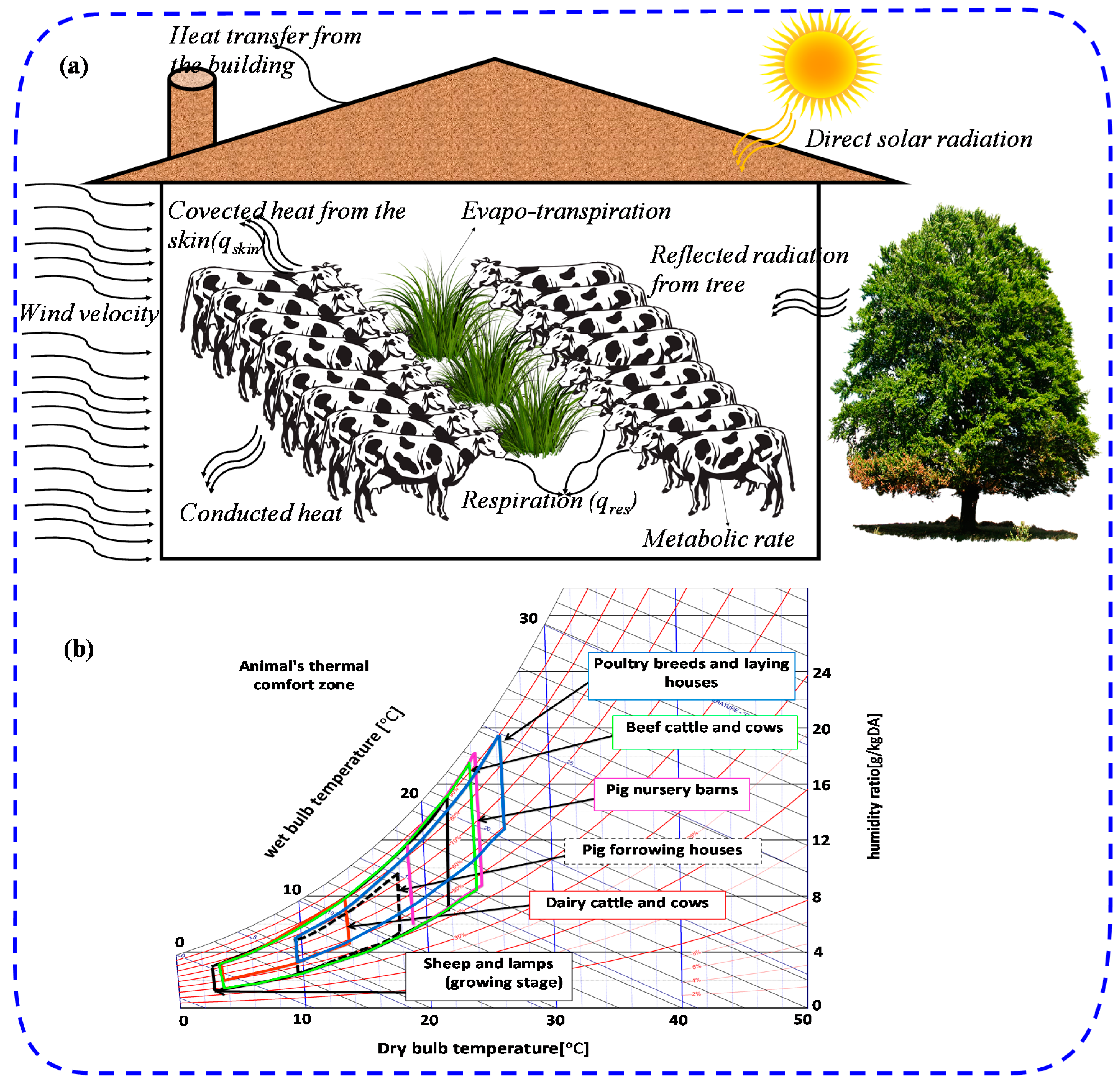
Air-Conditioning Requirements for Animals

Livestock is a neglected area of research in the agriculture sector especially in developing countries like Pakistan [4,22,30]. Small farmers have no idea about the thermal comfort of the livestock animals. Moreover, there is not any proper air-conditioning system available in the market for the thermal comfort of animals [31,32,33,34,35,36,37]. Hence, AC is a dire need for livestock’s thermal comfort for different applications especially at small levels in developing countries. Otherwise, fertility and milk production can be damaged due to heat stress in animals [31,32]. The heat-transfer phenomena between animals and the surrounding air is shown in Figure 1a. Therefore, to attain the thermal comfort conditions, an AC system is required for farm animals. Psychrometric illustration of the ideal thermal comfort regions for livestock applications is represented in Figure 1b. There are many ways for heat transfer to occur in the environment e.g., convection, conduction, and radiation that are further caused by evaporation, evapo-transpiration, and wind velocity etc. However, metabolic rate is also a key parameter to measure cooling requirements for farm animals [38,39,40,41,42]. In addition, heat transfer through buildings is considered when designing an AC system.
The idea of this paper is to check the feasibility of EC systems and/or those combined with desiccant air-conditioning system for livestock application. These are well known air-conditioning techniques, but the application is almost zero as far as livestock sector is concerned. This paper aims at the novelty of AC system configurations for livestock application in Pakistan.

2. Proposed Air-Conditioning (AC) Systems

The present study focuses on the different AC systems including the M-cycle evaporative cooling (MEC) system, desiccant AC system (DAC) and M-cycle based AC system (M-DAC). In this study, performance of these systems is evaluated and the feasibility of these systems for climatic situations of Multan (Pakistan) is checked. A brief description of these systems is given below.

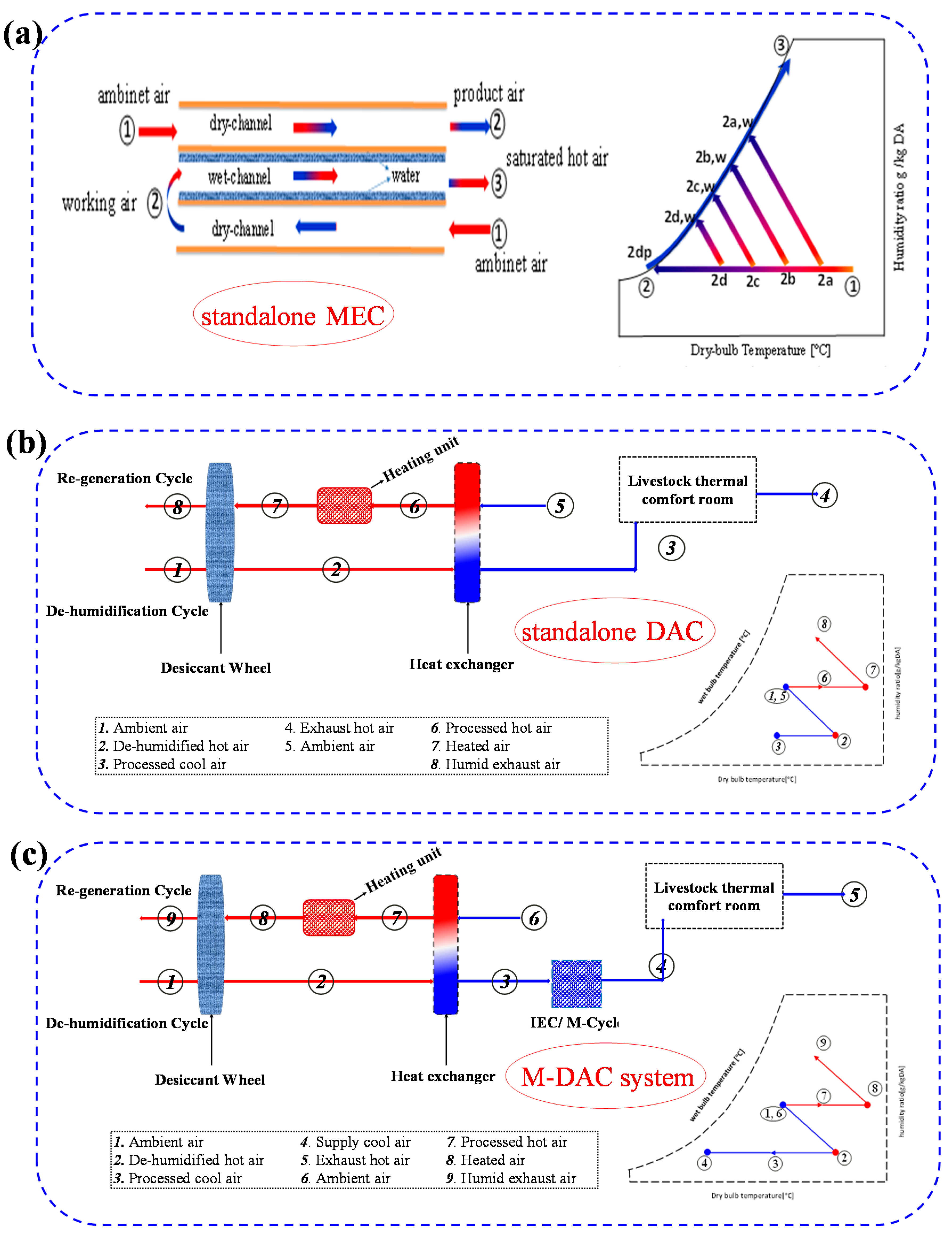
2.1. Stand-Alone M-Cycle Evaporative Cooling System (MEC)

Air-conditioning through water vapor evaporation is an ancient technique and mainly categorized into two types depending upon the HMX structure. Direct EC system has simple formation where air has contact with water directly, gets cool and humidify. Wet-bulb effectiveness of the MEC system is 100% theoretically, but in an applied scenario, the value of wet-bulb effectiveness remains significantly below the theoretical level. An indirect EC system comprises of two isolated channels i.e., dry channel (product channel) deliver air to working zone, wet channel served as working channel. Air traveling through the wet side obtains heat from the connected dry side through evaporation of water which lowers the temperature in the dry side towards wet bulb. Conversely, air travelling through the dry side cools down due to heat transfer through convection with the adjacent wet side.
Figure 2a shows the operational principle with psychrometric behavior of a dew-point M-cycle based EC system. It consists of three channels: two of them are dry and one of them is wet which is sandwiched between the dry channels. Ambient air is sensibly cooled down with constant humidity passing through the dry channel as shown by path 1–2 in Figure 2a losing heat to a nearby wet channel supplied to conditioned zone. Whereas working air travelling in wet channel as expressed by path 2–3 in Figure 2a is humidified through evaporation of water by absorbing heat and being eructed to the atmosphere, it can be further utilized for heat recovery processes. The M-cycle EC system just distracts the cooled air 2 into the wet side as a working air to apply the pre-cooling concept [33]. This different flow pattern causes the consecutive decrease in dry-bulb temperature (1-2; 2a; 2b; 2c; 2d) in the dry channel and wet-bulb temperature (1w-2aw; 2bw; 2cw; 2dw) in the wet channel [34]. In ideal heat transfer conditions, the consecutive decrease in temperature (dry bulb) results in the inlet air temperature approaching to dewpoint. Depending upon the operational principle, the M-cycle’s working and product channels can be interchanged.

2.2. Stand-Alone Desiccant AC System (DAC)

Desiccant AC systems (DACs) are gaining popularity in the regions where humidity is relatively high. A desiccant AC system is appropriately used for dehumidification of the air and the air temperature increases. The schematics of a desiccant AC system are illustrated by Figure 2b. A typical desiccant AC system contains a desiccant unit, a heat-exchanger unit (HX) and a heating unit. A desiccant unit is used for the dehumidification of air, a heat exchanger is used for normalizing the temperature to the surroundings, and a heating unit is used for heating air for regeneration of the desiccant’s unit. Then ambient air travelled through the desiccant unit from 1 to 2 in Figure 2b where air dehumidifies and the air temperature increases. After that, dehumidified air travelled through the HX unit from 2 to 3 which resulted in lowering the temperature of air as ambient air, theoretically. Then, that air can be used for the sole purpose of air conditioning for different applications especially in the northern arid areas of Pakistan where controlling temperature is not required. Conversely, ambient air passes through the heat exchanger from 5 to 6 and then passes through the heating unit from 6 to 7 which increases the air temperature. This heated air is used to regenerate the desiccant unit from 7 to 8 and the air is released to the environment. Psychrometric representation of the working of stand-alone desiccant AC system is illustrated in the Figure 2b.

2.3. M-Cycle Supported Desiccant AC System (M-DAC)

An M-cycle supported desiccant AC system (M-DAC) is used in the regions where humidity and temperature are very high. M-DAC system is appropriately used to dehumidify the air and the air temperature decreases, simultaneously. Figure 2c shows a schematic diagram of an M-DAC system. A typical M-DAC system contains a desiccant unit, a heat-exchanger unit, an evaporative cooling system and a heating unit. The desiccant unit is used for the dehumidification of air, the heat exchanger is used for normalizing the temperature to the surroundings, the MEC system is used to decrease the temperature of air, and a heating unit is used for heating air for regeneration of the desiccant unit. Then ambient air travels through the desiccant unit from 1 to 2 in Figure 2c where air is dehumidified and the air temperature increases. After that, dehumidified air travels through the HX unit from 2 to 3 which results in lowering down the temperature of air as ambient air, theoretically. Next, the air passes through the EC system (M-cycle) which decreases the temperature of the air. Then, that air can be used for the sole purpose of air-conditioning for different applications especially in southern areas of Pakistan where controlling both thermal parameters (humidity and temperature) are mandatory. Conversely, ambient air passes through the heat exchanger from 6 to 7 and then passes through the heating unit from 7 to 8 which increases the temperature of the air. This heated air is then used for regeneration of the desiccant unit from 8 to 9 and the air is released to the environment. Psychrometric representation of the working of an M-cycle supported desiccant AC system is illustrated in Figure 2c.

3. Materials and Methods

Desiccant is a material that has ability to adsorb water. Adsorption of desiccant material depends on the material properties and how it works with the water [35]. Many desiccant materials have been used for this specific work [9]. However, silica-gel based composite adsorbent is used in this research. Silica-gel is not an expensive, corrosive or environmentally polluting material [22,36]. It is also easily available from the local market in developing countries. The experimental structure and manufacturing of M-HMX is discussed below.

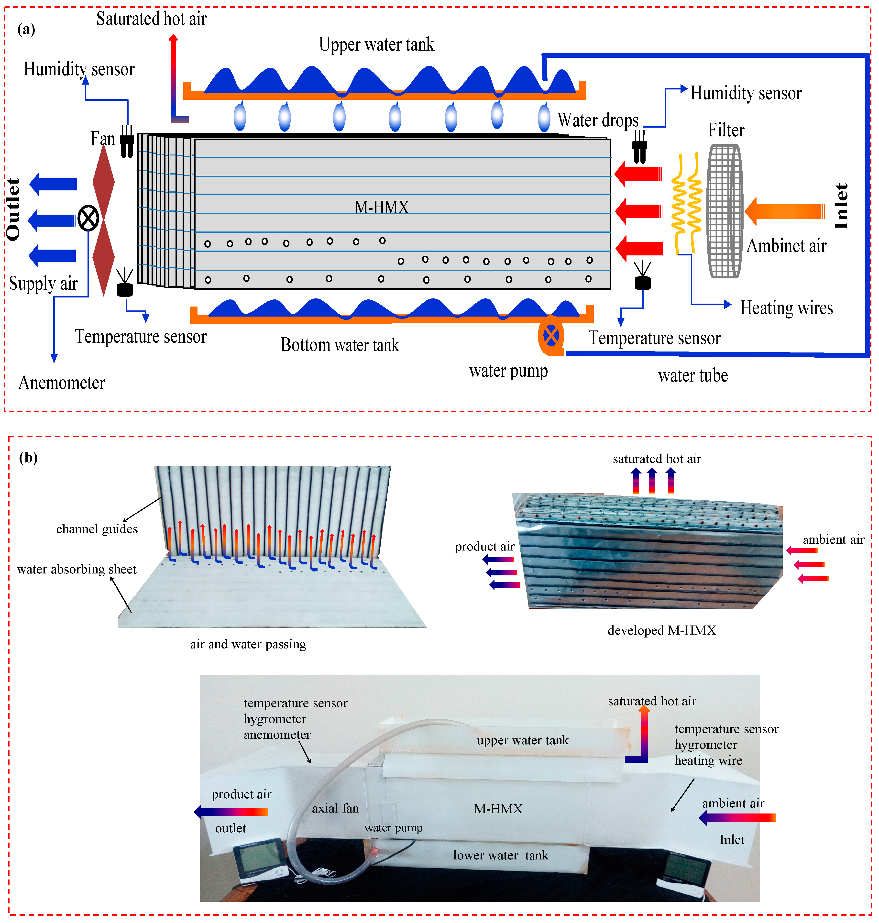
3.1. Experimental Section

The experimental setup consists of 33 fibrous material coated aluminum sheets. The fibrous material is hydrophilic in nature with sorption and desorption capacity up to 280 g/m2. An aluminum sheet of thickness 0.15 mm is selected for dry side of channels due to good thermal conduction properties and waterproof capability. Fibrous material of 0.3 mm thickness is chosen for wet sides, owing to its good hydrophilic nature. To keep the minimum difference of temperature between wet and dry sides of the sheet, and thickness should not more than 0.5mm [37]. The combined thickness of aluminum and the fibrous sheet become 0.45 mm after combining, that shows maximum thermal conductance between adjacent dry and wet sides. Then, these sheets are placed on one another, parted by guides of channels that are fixed on one of the sides of the sheet as shown in Figure 3a. Rubber-like material is used to make channel guides that are set laterally with the dry sides’ length and the connected wet sides’ width to make a crossflow pattern inside the HX.
Furthermore, laterally with the length of the dry sides, regularly circulated holes are punched to divert air from the dry channel side to the wet channel side as working air. The working air enters perpendicularly from dry to wet sides which is considered as uniformly distributed along the wet sides. Air passing through the wet channels make it humid due to water vapor evaporation into the air. As the humid air passed from one side to the other side of the wet channels, it transfers the cooling effect into the dry channel due to channel to channel heat transfer. Finally, the humid air is exhausted into the atmosphere, whereas, the product air (from dry channels) is sensibly cooled and supplied to the conditioning space. Details of the MEC working concept are provided in the authors’ previous work [23,30,38]. To study each sheet of M-HMX that consists 20 wet and 8 dry channels along the width and length of M-HMX of 4 mm height and 25 mm wide, consecutively as shown in Figure 3a. Dry channel’s length is 0.51 m whereas the wet channel is about 0.23 m extended. Amongst 8 dry channels, 5 are employed as product air channels while the last three from the bottom, serving as working air channels as shown in Figure 3b. Each channel among last three has 10 holes, each of them has 4 mm diameter for the air entrance (working) from the dry to wet channel side. The exact 4 mm diameter of each hole selected for the purposes to permit exactly 1/10 of 1/3 of total working air of dry side to wet side through channels [34].
The experimental setup comprises the M-cycle supported cross flow heat mass exchanger (M-HMX) with the 15 W axial fan at outlet. Water flows from top to bottom tank passing through wet channels. To ensure the complete saturation of wet channels, a submersible pump is placed at bottom reservoir for continuous circulation of water from bottom to top tank. To measure the parameters, sensors for temperature and humidity were being installed with an anemometer at both ends of the system. The system also equipped with heating wires (1 KW) to heat the incoming air for testing and evaluation. The whole unit is completely insulated with plastic sheet of 3 mm thickness to avoid heat losses shown in Figure 3b.

3.2. Load Calculation for Livestock Application

In the present study, thermal comfort conditions have been estimated theoretically for livestock animals for optimum output. Different thermal parameters (humidity and temperature) are required for various species and breeds of animals [38]. The heat and mass transfer phenomena between livestock animals and surrounding environment are illustrated in Figure 1a which are: convection, evaporation, radiation, conduction, evapo-transpiration, metabolism rate (transfer of heat through skin) and wind velocity etc. Transfer of heat through buildings is also significant when designing the building for animals’ comfort. The temperature-humidity index (THI) is a distinctive parameter to calculate the environmental thermal stability condition for animals. There are some fixed values for the thermal stability for cows (Holstein Friesian) which are shown in Table 1 [32]. The total heat load which needs to be air-conditioned can be estimated by Equation (1) to Equation (8). Total heat-load is the summation of heat-load of animals and building as depicted in Equation (8). Total heat load of the animals can be estimated by using Equation (1) [39].
Q a = q skin + q res + S
where, heat-load of animals is denoted by ‘Qa’ in kW. Heat-load (partial) for the different sections is denoted by ‘q’ in kW and stored heat in the body is denoted by ‘S’ (S = 0, for ideal situation). The subscripts ‘a’ denotes animals and ‘res’ denotes respiration. Skin heat-load can be estimated by using Equation (2) and Equation (3) [39,40] as given below:
q skin = S A   M R
S A = 0.147   W 0.57
where, weight of animal in kg is denoted by ‘W’ and ‘SA’ denotes skin area in m2. Furthermore, ‘MR’ represents the rate of metabolism [met]. Furthermore, respiration heat-load can be estimated which is the summation of heat losses (evaporation + convection) by using Equation (4) to Equation (6) present in ASHRAE [39].
q res = C res + E res  
C res = [ 0.0014   M R   ( 34 T a ) ]
E res = [ 0.0173   M R   ( 5.87 P a ) ]
where, ‘C’ and ‘E’ represents heat losses (convection and evaporation) from the respiration in [W/(h.m2)], respectively. ‘Ta’ and ‘Pa’ denote temperature and vapor pressure of ambient air in °C and in kPa, correspondingly. Transfer of heat through buildings can be estimated by using Equation (7).
Q b = U   A   Δ T
where, heat load of the buildings is denoted by ‘Qb’ in kW. The total heat-transfer coefficient of the building is denoted by ‘U’ in [W/ (m2.K)], building area is denoted by ‘A’ in m2 and temperature difference is denoted by ‘∆T’ in K or °C. Total heat-load required for livestock animals can be estimated by Equation (8).
Q = Q a + Q b
where, total heat-load is denoted by ‘Q’ in kW. Moreover, THI (temperature–humidity index) is a distinctive parameter to calculate the environmental thermal stability condition for animals. THI can be estimated by using Equation (9) [31,32].
THI = ( 1.8   T + 32 ) [ ( 0.55 0.0055   RH )   ( 1.8   T 26 ) ]
where, temperature in [°C] and relative humidity in [%] are denoted by ‘T’ and ‘RH’, accordingly. THI is dependent on humidity and temperature. So, there are some distinctive THI values which describe the environmental thermal stability given in the literature [32] shown in Table 1.

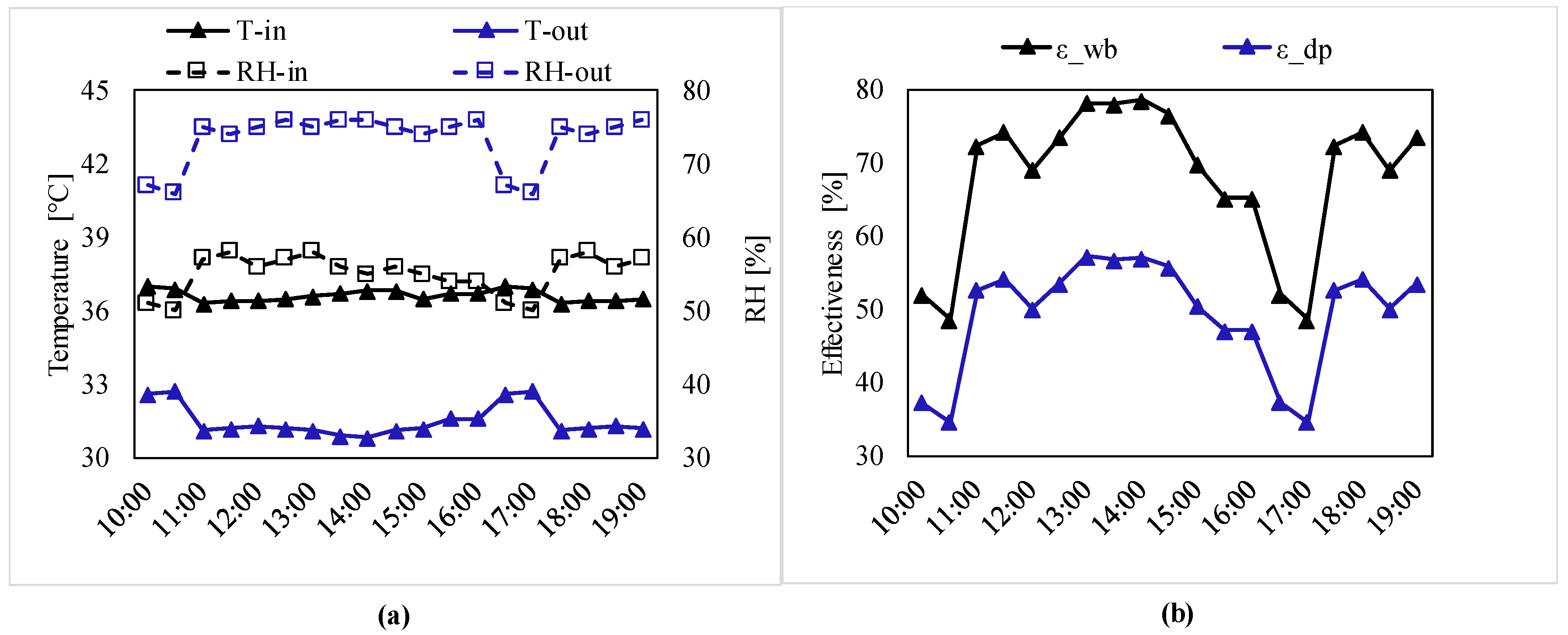
3.3. Methodology for Maisotsenko-Cycle Evaporative Cooling (MEC) System

During the construction of M-HMX following assumptions were considered with following suppositions.
  • The whole system was thermally in-conductance;
  • Water as coolant agent with no corrosion effect;
  • Wet channels remained completely saturated because of uniform water distribution.
Performance of M-HMX was evaluated through measurements of given parameters:
  • Relative humidity at inlet and outlet sections (RHin, RHout);
  • Dry-bulb temperature at inlet and outlet sections (Tin, Tout);
  • Air velocity at outlet section (Vout).
The performance of M-HMX could be checked in terms of effectiveness that is mainly categorized into wet bulb effectiveness (εwb) and dewpoint effectiveness (εdp). Furthermore, εwb can be defined as the ratio of the difference of air temperature (inlet and outlet) to the difference of air temperature (inlet and its corresponding wet bulb). Mathematically, it can be expressed by using Equation (10).
ε wb = T in , a T out , a T in , a T wb , a
Likewise, εdp can be defined as the ratio of difference of air temperature (inlet and outlet) to the difference of air temperature (inlet and its corresponding dewpoint). Mathematically, it can be expressed by using Equation (11).
ε dp = T in , a T out , a T in , a T dew , a

3.4. Methodology for Desiccant AC System (DAC)

The present study mainly focuses on the AC systems (stand-alone desiccant AC and M-cycle supported desiccant AC) for the comfort of livestock animals thermally. Hence, there are a couple of equations for theoretical evaluation of M-cycle supported desiccant AC systems’ performance present in the literature [4,22,36,41]. The desiccant unit’s performance is estimated by an analogy method from Equation (12) to Equation (15) given by Panaras et al. [36,41]. In this method, combined potentials in terms of temperature and absolute humidity (F1 and F2) are calculated by Equation (12) and Equation (13) and then these combined potentials can be used for the measurements of efficiencies from Equation (14) and Equation (15) leading to the measurement of dehumidified air temperature and humidity ratio, theoretically.
F 1 , ip = A 1 ( T ip + 273.15 ) 1.49 + B 1 ( w ip 1000 ) C 1
F 2 , ip = ( T ip + 273.15 ) 1.49 A 2 B 2 ( w ip 1000 ) C 2
η F 1 = F 1 , 2 F 1 , 1 F 1 , 8 F 1 , 1
η F 2 = F 2 , 2 F 2 , 1 F 2 , 8 F 2 , 1
where combined potentials in terms of absolute humidity and temperature of desiccant wheel and efficiencies related to these potentials are denoted by (F1 and F2) and (ηF1, ηF2), accordingly. The typical values of efficiencies for the high-performance desiccant wheel are 0.05 for ηF1, and 0.95 for ηF2. Moreover, humidity ratio and temperature in [kg/kg-DA] and [°C] are denoted by ‘w’ and ‘T’, accordingly. ‘ip’ indicates different states of air according to system as expressed in Figure 2b,c.
The values of the constants used in the Equations (12) and (13) are given in Table 2. Furthermore, heat exchanger is evaluated by Equation (16) given by ASHRAE [39]. The heat-exchanger effectiveness can be considered (0.9) for the high-performance system.
T 3 = T 2 , db ε hx   ( T 2 , db T 1 , db )
where, temperature in [°C] and efficiency of heat exchanger are denoted by ‘T’ and ‘εhx’, respectively. 1, 2, 3 are the different states of air related to the schematics of the systems. Likewise, M-cycle based desiccant AC system has a surplus of the MEC unit which is evaluated by using Equation (17) developed in the literature [4].
T out = 6.70 + 0.2630   ( T in ) + 0.5298   ( w in )
where, humidity ratio and temperature in [kg/kg-DA] and [°C] are denoted by ‘w’ and ‘T’, respectively. The subscripts ‘in’ represent the inlet and ‘out’ represent the outlet conditions for the MEC unit. Overall performance can be estimated in terms of coefficient of performance (COP) for both desiccant-based systems. Thermal COP can be estimated by using Equation (18) presented in ASHRAE [39].
COP = Cooling   capacity Heat   input = m · S A m · reg   Q input | h in , amb h out , supply |
where, the flow rate of air in [kg/s] is represented by ‘ṁ’. The subscripts ‘SA’ and ‘reg’ denotes the supply air flow and regeneration air, accordingly. Enthalpy in [J] is denoted by ‘h’ and can be estimated by using Equation (19) presented in ASHRAE [39]. COP can be estimated by using enthalpy at different steps of the air in both desiccant based AC systems as depicted in Figure 2b,c.
h = 1.006   T + w   ( 2501 + 1.86   T )
These all equations are used for performance evaluation of the proposed AC options theoretically for Multan, Pakistan.

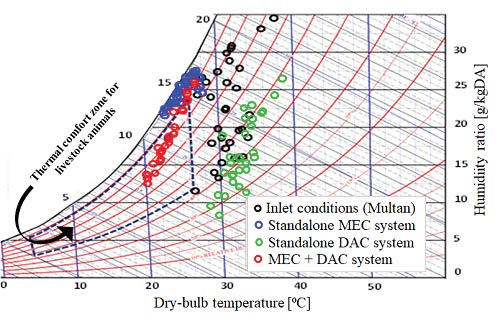
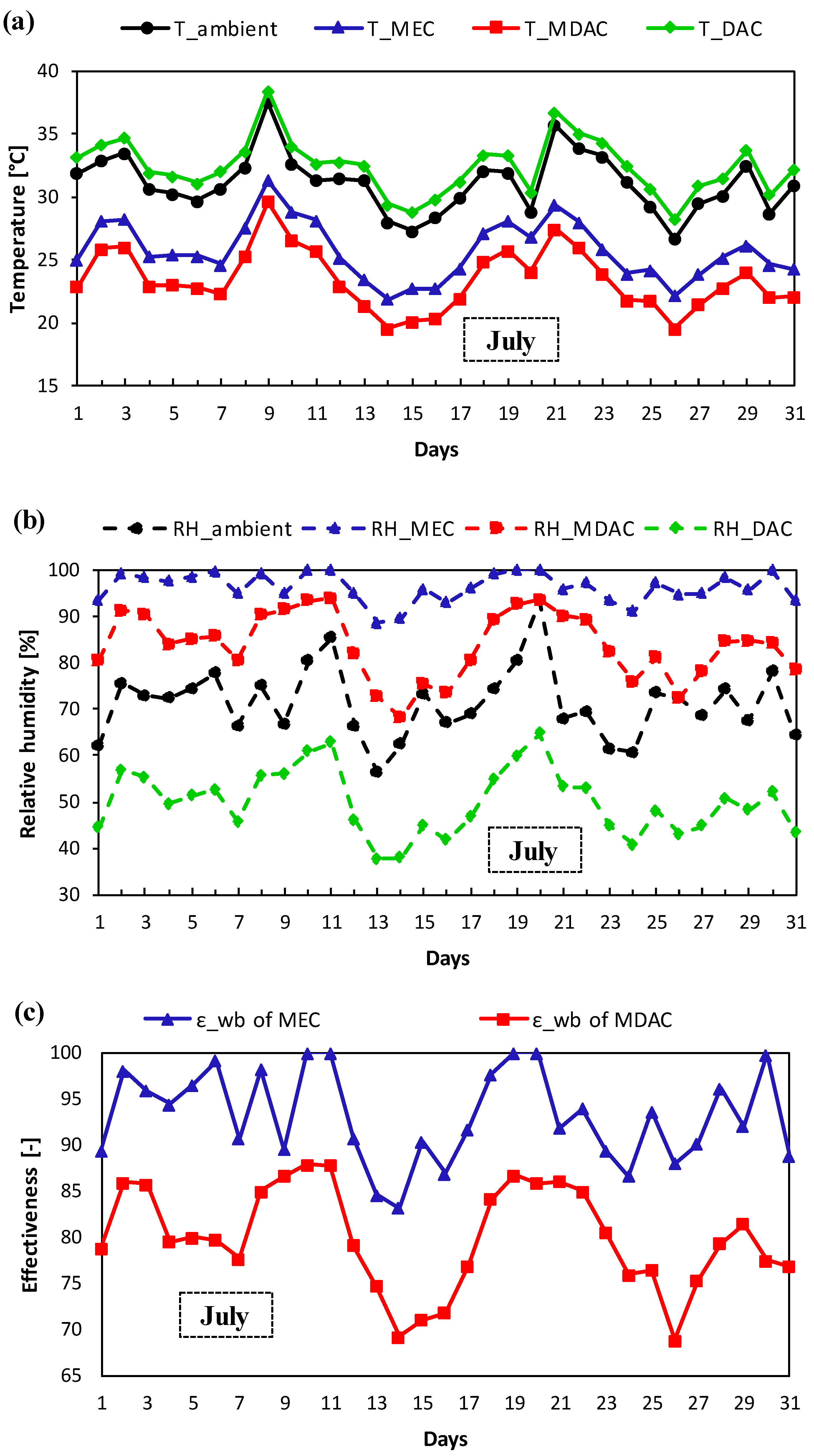
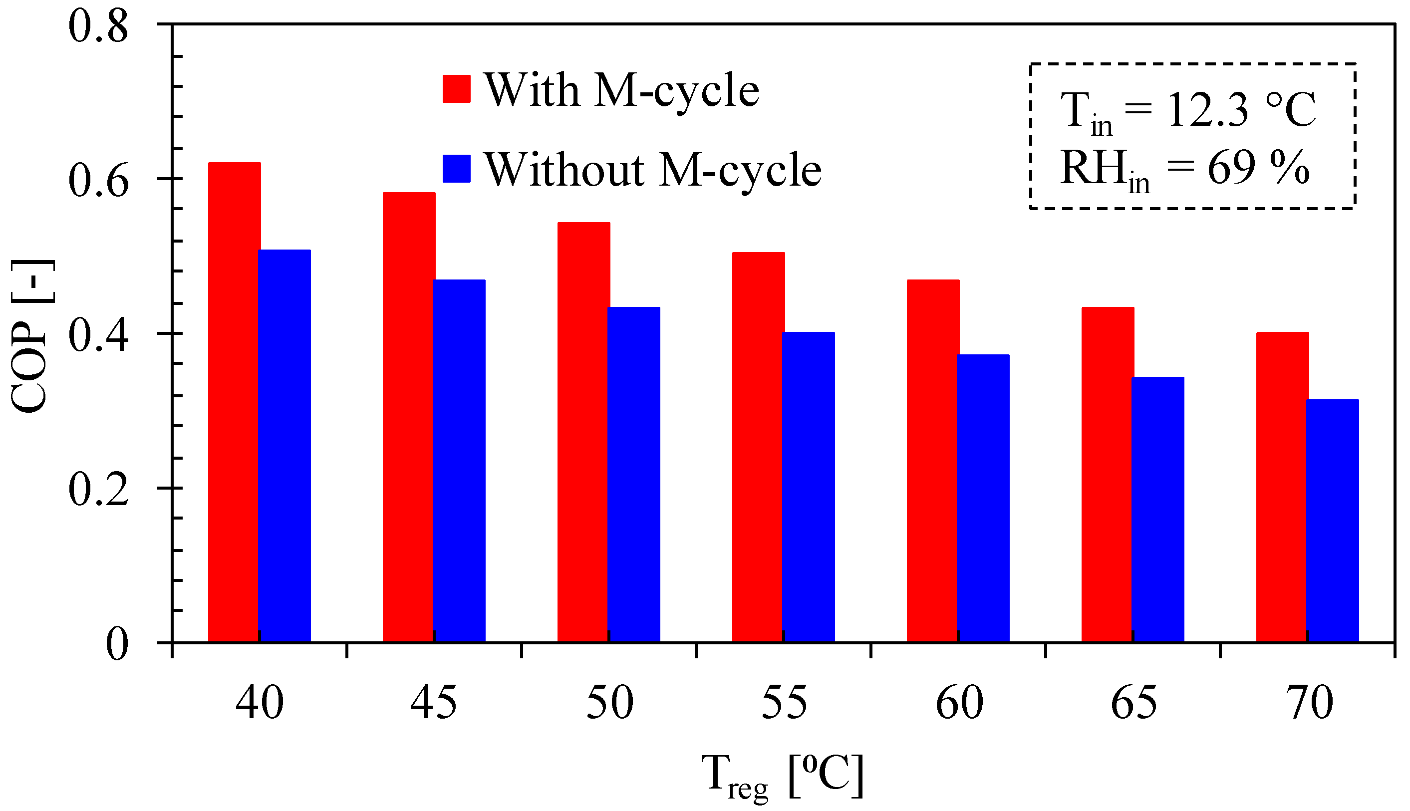
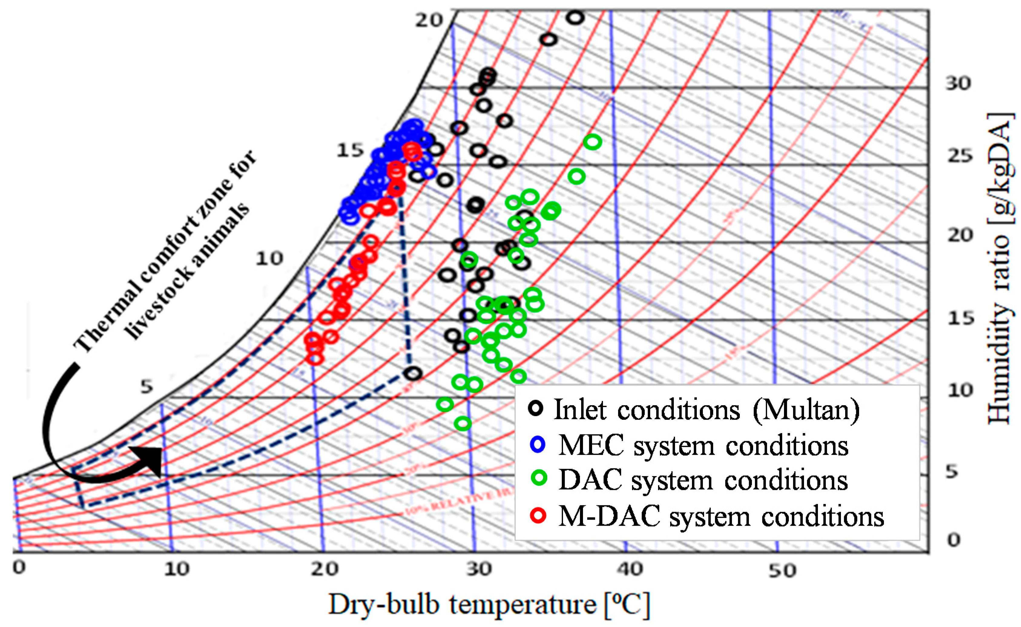
4. Results and Discussion

Results were collected throughout the summer season for Multan’s indigenous conditions, in two cases. The basic purposes of these experiments were to gauge the performance evaluation of M-HMX under ambient conditions in representative day time of the summer season for Multan, Pakistan and for the evaluation of desiccant AC system’s performance. The results were collected on hourly bases (10:00 to 19:00) in July to check the dynamic performance of the proposed AC systems as shown in Figure 4; analysis of experimental MEC system on hourly basis for 15 July for Multan (Pakistan): (a) outlet relative humidity and temperature; and (b) effectiveness. The inlet ambient air temperature varies from 35 °C (morning) and gradually increase to maximum value 38 °C (afternoon) and then declines to 36.5 °C (evening), whilst the inlet relative humidity is continuously changing from minimum value 50% to maximum value 60% throughout the day.
Moreover, the change in relative humidity and temperature at outlet section is not significant ranging from 28 to 32 °C and 65% to 80%, respectively for MEC system. The hourly performance in terms of wet bulb for MEC system is illustrated in Figure 4b with varying ranges from 46% to 78%. In the same context, the results were calculated on daily bases for July by the 20-year average data obtained from the METERONOME software to check the dynamic performance of proposed AC systems as shown in Figure 5; analysis of the proposed AC system options on daily basis for July month for Multan (Pakistan); (a) outlet temperature; (b) relative humidity; and (c) effectiveness. The daily performance of the MEC system in terms of RH and T ranges from 22 to 32 °C and 90% to 100%, respectively. Likewise, the daily performance of M-cycle based desiccant AC system in terms of RH and T ranges from 18 to 28 °C and 70% to 90%, accordingly. The daily performance in terms of wet-bulb effectiveness for the MEC system varies from 85% to 100% due to the non-working of the system. Conversely, the daily performance in terms of wet bulb for M-cycle based desiccant AC system varies from 70% to 86%. Temperature difference between inlet and outlet sections in first 10 days is less comparative to last days because of humidity variations. The same trend was obtained in wet bulb and dewpoint effectiveness values. The purpose of these experiments was to estimate the performance of proposed AC systems used in this study under static inlet conditions instead of dynamic situations. The impact of various inlet parameters has been studied keeping all other parameters unchanged. COP of the desiccant-based AC system options is shown graphically in Figure 6 which shows the significance of the M-cycle based desiccant AC system. It is clear from graph that the COP of the M-DAC system is higher than the standalone DAC system. COP is calculated for the static conditions (T of 12.3 °C and RH of 69%). The flow rate of air is considered unity for this study.
Figure 7 shows the ambient and processed air conditions from the proposed AC system options (MEC, DAC and M-DAC) drawn on psychrometric chart. Figure 7 clearly shows that ambient conditions are not feasible in July for the comfort of livestock application (thermally) due to the monsoon season. Consequently, air conditions from the standalone MEC and stand-alone desiccant AC is also not appropriate for the climatic situations of Multan because of high relative humidity and temperature. Therefore, the M-DAC system is appropriate for the ambient air situations of Multan including the monsoon season. Moreover, M-DAC is also feasible for the humid climatic conditions (i.e., coastal and northern areas of Pakistan).
Figure 8 shows the temperature-humidity index (THI) for different arrangements of AC and cooling system options used in this study. Figure 8 shows the temperature–humidity index of inlet and outlet air for the proposed AC system options under Multan summer conditions: (a) stand-alone MEC system; (b) stand-alone desiccant AC system; and (c) M-cycle based desiccant AC system. It is clear from Figure 8 that the values of THI obtained from the stand-alone MEC system is much greater than the typical permissible limit required for the thermal neutral region as described above for July to September. Consequently, heat stress is being produced while using stand-alone MEC system for ambient air situations of Multan in these months.
In the same context, the stand-alone desiccant AC system is also not appropriate for ambient situations for Multan (Pakistan) as the cooling is also required for comfort of livestock applications (thermally). Conversely, values of THI obtained from the M-cycle based desiccant AC system are less than the permissible limit required for the thermal neutral region and are feasible for the comfort of livestock animals (thermally). Therefore, thermal stability is done by using the M-cycle supported desiccant AC system for ambient air situations for Multan in monsoon season as well.
Table 3 shows the monthly based feasibility of the proposed AC system options for the ambient air situations of Multan (Pakistan). Ticks show the feasibility of the system in relative months, cross shows the non-feasibility and dash shows no need of air-conditioning in respective month. It is obvious from the table that the ambient conditions are feasible for the winter months (October to February) and there is no necessity for any AC system in that months. Consequently, stand-alone MEC system is not feasible for the monsoon season (July to September) when relative humidity in the air is very high. In the same context, the stand-alone desiccant AC system is not feasible for ambient air situations of Multan. Therefore, the M-cycle based desiccant AC system is appropriately feasible for the months including monsoon season for climatic situations of Multan (Pakistan).

5. Conclusions

The performance of M-cycle based cross flow heat-mass exchanger (M-HMX) and desiccant based AC systems are evaluated experimentally and theoretically in the present study under Multan’s climatic situations. Results indicate that the performance of the proposed systems largely depend upon the geometry of HMX and ambient air conditions. The M-cycle evaporative cooling (MEC) system has greater potential among all the evaporative cooling techniques for regions having high temperature with low humidity. However, the performance of the M-cycle was observed during experimental investigation evaporative cooling system for 15 July in the sense of wet-bulb effectiveness (εwb) which ranges from 46% to 78%. Conversely, the performance was observed during theoretical investigation of the M-cycle based desiccant AC system in terms of wet-bulb effectiveness (εwb) and COP ranges from 70% to 86% and up to 0.64, respectively. Moreover, for optimal performance of the MEC system, intake air velocity through product channels should not greater than 1.5 ms-1 and channel height should no longer than 4 mm. Likewise, the air pressure as well as regeneration temperature is also important in an M-cycle based desiccant AC system. Despite some wide fluctuations in humidity, MEC seems to perform better than DEC and IEC, comparatively. In contrast, the M-cycle supported desiccant AC system is much more suitable than that of the stand-alone M-cycle EC system. Also, the M-cycle based desiccant AC is appropriate for livestock application for ambient air situations of Multan in the monsoon season. This study suggests the future work which is dynamic simulation of proposed AC system options for livestock application at domestic and commercial levels.

Author Contributions

Conceptualization, M.K. and H.N.; methodology, M.S. and I.A.; validation, T.M., and Y.F.; formal analysis, H.N. and M.S.; investigation, T.M., Y.F., M.W.S. and Y.N.; writing—original draft preparation, M.K., H.N., and M.S.; visualization, M.U.; writing—review and editing, M.U., M.M.W., and I.A.; supervision, M.S.; project administration, M.S.; funding acquisition, M.S. All authors have read and agreed to the published version of the manuscript.

Funding

This research received no external funding.

Acknowledgments

The authors would like to thank Bahauddin Zakariya University, Multan-Pakistan for financial support under the Director Research/ ORIC grants (i) “Evaluation of solar chimney driven passive air-conditioning system for agricultural and livestock applications in Pakistan” and (ii) “Thermodynamic evaluation of low-cost air-conditioning systems for various applications”, awarded to Principal Investigator Muhammad Sultan. This research work has been carried out in the Department of Agricultural Engineering, Bahauddin Zakariya University, Multan-Pakistan. We acknowledge support for the Open Access fees by Hamburg University of Technology (TUHH) in the funding programme Open Access Publishing. The necessary copyright permissions are ensured accordingly for all copyrighted graphics, images, tables, and figures.

Conflicts of Interest

The authors declare no conflict of interest.

References

  1. Sultan, M.; El-Sharkawy, I.I.; Miyazaki, T.; Saha, B.B.; Koyama, S. An overview of solid desiccants dehumidification and air conditioning systems. Renew. Sustain. Energy Rev. 2015, 46, 16–29. [Google Scholar] [CrossRef]
  2. Sultan, M.; Miyazaki, T.; Koyama, S.; Khan, Z.M. Performance evaluation of hydrophilic organic polymer sorbents for desiccant air-conditioning applications. Adsorpt. Sci. Technol. 2017, 36, 1–16. [Google Scholar] [CrossRef] [Green Version]
  3. Sultan, M.; El-Sharkawy, I.I.; Miyazaki, T.; Saha, B.B.; Koyama, S. Experimental study on carbon-based adsorbents for greenhouse dehumidification. Evergreen 2014, 1, 5–11. [Google Scholar] [CrossRef]
  4. Sultan, M.; Miyazaki, T.; Niaz, H.; Shabir, F.; Ashraf, S.; Khan, Z.M.; Mahmood, M.H.; Reza, H.M.U. Thermodynamic assessment of solar chimney based airconditioning system for agricultural and livestock applications. In Proceedings of the 4th International Conference on Energy and Environment and Sustainable Development (EESD-2016), Jamshoro, Pakistan, 1–3 November 2016. [Google Scholar]
  5. Kottek, M.; Grieser, J.; Beck, C.; Rudolf, B.; Rubel, F. World map of the Köppen-Geiger climate classification update. Meteorol. Z. 2006, 15, 259–263. [Google Scholar] [CrossRef]
  6. Naphon, P. Study on the heat transfer characteristics of an evaporative cooling tower. Int. Commun. Heat Mass Transf. 2005, 32, 1066–1074. [Google Scholar] [CrossRef]
  7. Caliskan, H.; Dincer, I.; Hepbasli, A. Exergetic and sustainability performance comparison of novel and conventional air cooling systems for building applications. Energy Build. 2011, 43, 1461–1472. [Google Scholar] [CrossRef]
  8. Zhan, C.; Duan, Z.; Zhao, X.; Smith, S.; Jin, H.; Riffat, S. Comparative study of the performance of the M-cycle counter-flow and cross-flow heat exchangers for indirect evaporative cooling–paving the path toward sustainable cooling of buildings. Energy 2011, 36, 6790–6805. [Google Scholar] [CrossRef]
  9. Sultan, M.; Miyazaki, T.; Koyama, S. Optimization of adsorption isotherm types for desiccant air-conditioning applications. Renew. Energy 2018, 121, 441–450. [Google Scholar] [CrossRef]
  10. Caliskan, H.; Hepbasli, A.; Dincer, I.; Maisotsenko, V. Thermodynamic performance assessment of a novel air cooling cycle: Maisotsenko cycle. Int. J. Refrig. 2011, 34, 980–990. [Google Scholar] [CrossRef]
  11. ASHRAE. ASHRAE Handbook, Fundamentals; American Society of Heating, Refrigerating Air-Condition Engineers Inc.: Atlanta, GA, USA, 2005. [Google Scholar]
  12. Jiang, Y.; Xie, X. Theoretical and testing performance of an innovative indirect evaporative chiller. Solar Energy 2010, 84, 2041–2055. [Google Scholar] [CrossRef]
  13. Anisimov, S.; Pandelidis, D.; Danielewicz, J. Numerical analysis of selected evaporative exchangers with the Maisotsenko cycle. Energy Convers. Manag. 2014, 88, 426–441. [Google Scholar] [CrossRef]
  14. Costelloe, B.; Finn, D. Indirect evaporative cooling potential in air–water systems in temperate climates. Energy Build. 2003, 35, 573–591. [Google Scholar] [CrossRef] [Green Version]
  15. Wu, J.M.; Huang, X.; Zhang, H. Theoretical analysis on heat and mass transfer in a direct evaporative cooler. Appl. Therm. Eng. 2009, 29, 980–984. [Google Scholar] [CrossRef]
  16. Maheshwari, G.P.; Al-Ragom, F.; Suri, R.K. Energy saving potential of an indirect evaporative cooler. Appl. Energy 2001, 69, 69–76. [Google Scholar] [CrossRef]
  17. Gómez, E.V.; Martínez, F.J.R.; González, A.T. Experimental characterisation of the operation and comparative study of two semi-indirect evaporative systems. Appl. Therm. Eng. 2010, 30, 1447–1454. [Google Scholar] [CrossRef]
  18. Ray, W.T. Conditioning Liquids and Air and Other Gases. U.S. Patent 1986529, 1 January 1935. [Google Scholar]
  19. Anisimov, S.; Pandelidis, D. Theoretical study of the basic cycles for indirect evaporative air cooling. Int. J. Heat Mass Transf. 2015, 84, 974–989. [Google Scholar] [CrossRef]
  20. Cengel, Y.A. Heat and Mass Transfer: A Practical Approach with EES CD; McGraw-Hill Higher Education: New York, NY, USA, 2006. [Google Scholar]
  21. Anisimov, S.; Pandelidis, D. Numerical study of the Maisotsenko cycle heat and mass exchanger. Int. J. Heat Mass Transf. 2014, 75, 75–96. [Google Scholar] [CrossRef]
  22. Niaz, H.; Sultan, M.; Khan, Z.M.; Mahmood, M.H.; Niaz, Y. Thermodynamic investigation of M-cycle assisted open-cycle desiccant air conditioning systems. In IOP Conference Series: Materials Science and Engineering; IOP Publishing: Bristol, UK, 2018. [Google Scholar]
  23. Mahmood, M.H.; Sultan, M.; Miyazaki, T.; Koyama, S.; Maisotsenko, V.S. Overview of the Maisotsenko cycle–A way towards dew point evaporative cooling. Renew. Sustain. Energy Rev. 2016, 66, 537–555. [Google Scholar] [CrossRef]
  24. Riangvilaikul, B.; Kumar, S. Numerical study of a novel dew point evaporative cooling system. Energy Build. 2010, 42, 2241–2250. [Google Scholar] [CrossRef]
  25. Lee, J.; Choi, B.; Lee, D. Comparison of configurations for a compact regenerative evaporative cooler. Int. J. Heat Mass Transf. 2013, 62, 192–198. [Google Scholar] [CrossRef]
  26. Gillan, L. Maisotsenko cycle for cooling process. Clean Air 2008, 9, 1–18. [Google Scholar]
  27. Hasan, A. Indirect evaporative cooling of air to a sub-wet bulb temperature. Appl. Therm. Eng. 2010, 30, 2460–2468. [Google Scholar] [CrossRef]
  28. Zube, D.; Gillan, L. Evaluating Coolerado Corportion’s heat–mass exchanger performance through experimental analysis. Int. J. Energy Clean Environ. 2011, 12, 101–116. [Google Scholar] [CrossRef]
  29. Ren, C.; Yang, H. An analytical model for the heat and mass transfer process in indirect evaporative cooling with parallel/counter flow configuration. Int. J. Heat Mass Transf. 2006, 49, 617–627. [Google Scholar]
  30. Sultan, M.; Miyazaki, T.; Mahmood, M.H.; Khan, Z.M. Solar assisted evaporative cooling based passive air-conditioning system for agricultural and livestock applications. J. Eng. Sci. Technol. 2018, 13, 693–703. [Google Scholar]
  31. Karimi, M.T.; Ghorbani, G.R.; Kargar, S.; Drackley, J.K. Late-gestation heat stress abatement on performance and behavior of Holstein dairy cows. J. Dairy Sci. 2015, 98, 6865–6875. [Google Scholar] [CrossRef] [Green Version]
  32. Palacio, S.; Bergeron, R.; Lachance, S.; Vasseur, E. The effects of providing portable shade at pasture on dairy cow behavior and physiology. J. Dairy Sci. 2015, 98, 6085–6093. [Google Scholar] [CrossRef]
  33. Zhao, X.; Li, J.M.; Riffat, S.B. Numerical study of a novel counter-flow heat and mass exchanger for dew point evaporative cooling. Appl. Therm. Eng. 2008, 28, 1942–1951. [Google Scholar] [CrossRef]
  34. Heidarinejad, G.; Bozorgmehr, M.; Delfani, S.; Esmaeelian, J. Experimental investigation of two-stage indirect/direct evaporative cooling system in various climatic conditions. Build. Environ. 2009, 44, 2073–2079. [Google Scholar] [CrossRef]
  35. Sultan, M.; El-Sharkawy, I.I.; Miyazaki, T.; Saha, B.B.; Koyama, S.; Maruyama, T.; Maeda, S.; Nakamura, T. Water vapor sorption kinetics of polymer based sorbents: Theory and experiments. Appl. Therm. Eng. 2016, 106, 192–202. [Google Scholar] [CrossRef]
  36. Panaras, G.; Mathioulakis, E.; Belessiotis, V.; Kyriakis, N. Theoretical and experimental investigation of the performance of a desiccant air-conditioning system. Renew. Energy 2010, 35, 1368–1375. [Google Scholar] [CrossRef]
  37. Alonso, J.F.S.J.; Martinez, F.J.R.; Gomez, E.V.; Plasencia, M.A.G. Simulation model of an indirect evaporative cooler. Energy Build. 1998, 29, 23–27. [Google Scholar] [CrossRef]
  38. Sultan, M.; Miyazaki, T. Energy-efficient air-conditioning systems for nonhuman applications. In Refrigeration; IntechOpen: London, UK, 2017; pp. 97–117. [Google Scholar]
  39. ASHRAE. Handbook of Fundamentals; Published by American Society of Heating, Refrigerating and Air-Conditioning Engineers Inc.: Atlanta, GA, USA, 2009. [Google Scholar]
  40. Wang, X.; Zhang, G.; Choi, C.Y. Effect of airflow speed and direction on convective heat transfer of standing and reclining cows. Biosyst. Eng. 2018, 167, 87–98. [Google Scholar] [CrossRef]
  41. Panaras, G.; Mathioulakis, E.; Belessiotis, V. Solid desiccant air-conditioning systems–design parameters. Energy 2011, 36, 2399–2406. [Google Scholar] [CrossRef]
  42. Sultan, M.; Niaz, H.; Miyazaki, T. Investigation of Desiccant and Evaporative Cooling Systems for Animal Air-Conditioning. In Refrigeration and Air-Conditioning; IntechOpen: London, UK, 2019. [Google Scholar]
Figure 1. Livestock applications: (a) heat and mass transfer phenomena between farm animals and surrounding environment, adapted with permission from [42], IntechOpen, 2019; and (b) psychrometric illustration of thermal comfort regions for livestock animals, reproduced with permission from [38], IntechOpen, 2017.
Energies 13 02675 g001
Figure 2. Proposed air-conditioning system options for this study: (a) stand-alone Maisotsenko-cycle evaporative cooling (MEC) system; (b) stand-alone desiccant air-conditioning (AC) system; and (c) M-cycle supported desiccant AC system.
Energies 13 02675 g002
Figure 3. Schematic diagrams of M-cycle evaporative cooling system: (a) schematic diagram, and (b) pictorial representation of the experimental apparatus.
Energies 13 02675 g003
Figure 4. Analysis of experimental MEC system on hourly basis for 15 July for Multan (Pakistan): (a) outlet relative humidity and temperature; and (b) effectiveness.
Energies 13 02675 g004
Figure 5. Analysis of proposed AC system options on daily basis for July for Multan (Pakistan); (a) outlet temperature; (b) relative humidity; and (c) effectiveness.
Energies 13 02675 g005
Figure 6. Coefficient of performance (COP) of desiccant-based AC system options equipped (with/without) M-cycle unit.
Energies 13 02675 g006
Figure 7. Psychrometric based feasibility analysis of proposed AC system options in terms of relative humidity (RH) and temperature (T) for month of July.
Energies 13 02675 g007
Figure 8. Analysis of proposed AC system options on monthly basis THI for Multan (Pakistan); (a) Stand-alone MEC system; (b) Stand-alone desiccant AC system; and (c) M-cycle based desiccant AC system.
Energies 13 02675 g008
Table 1. The values of the temperature–humidity index (THI) used in the above equations.
THI ValueDescription
<68Thermal neutral region
68–72Thermally stable region
72–80Moderate heat stress region
>80Severe heat stress region
Table 2. The constants values used in the methodology of desiccant air-conditioning (DAC) system.
ConstantValueConstantValue
A1−2865A26360
B14.344B21.127
C10.8624C20.07969
Table 3. Feasibility of proposed systems for livestock air-conditioning in Multan, Pakistan.
Months 1Air-Conditioning System Options
Standalone MEC SystemStandalone DAC SystemM-DAC System
March
April
May
June
July
August
September
1 Ambient air situations for winter months (October to February) are within range for the livestock AC application.

