Ground Fault Detection Using Hybrid Method in IT System LVDC Microgrid

Abstract
:1. Introduction
2. Hybrid Detection Method Using Pulsating Signal Generator and DWT
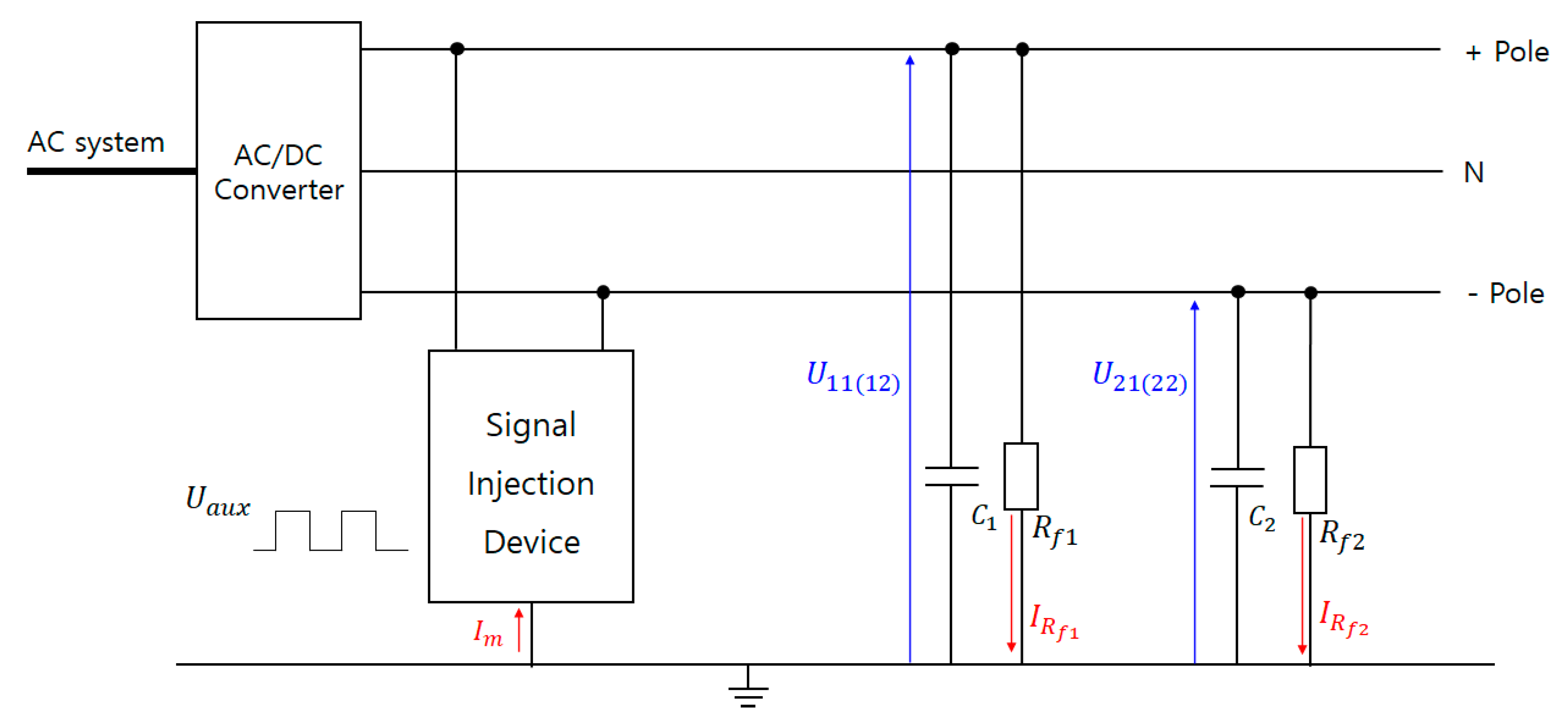
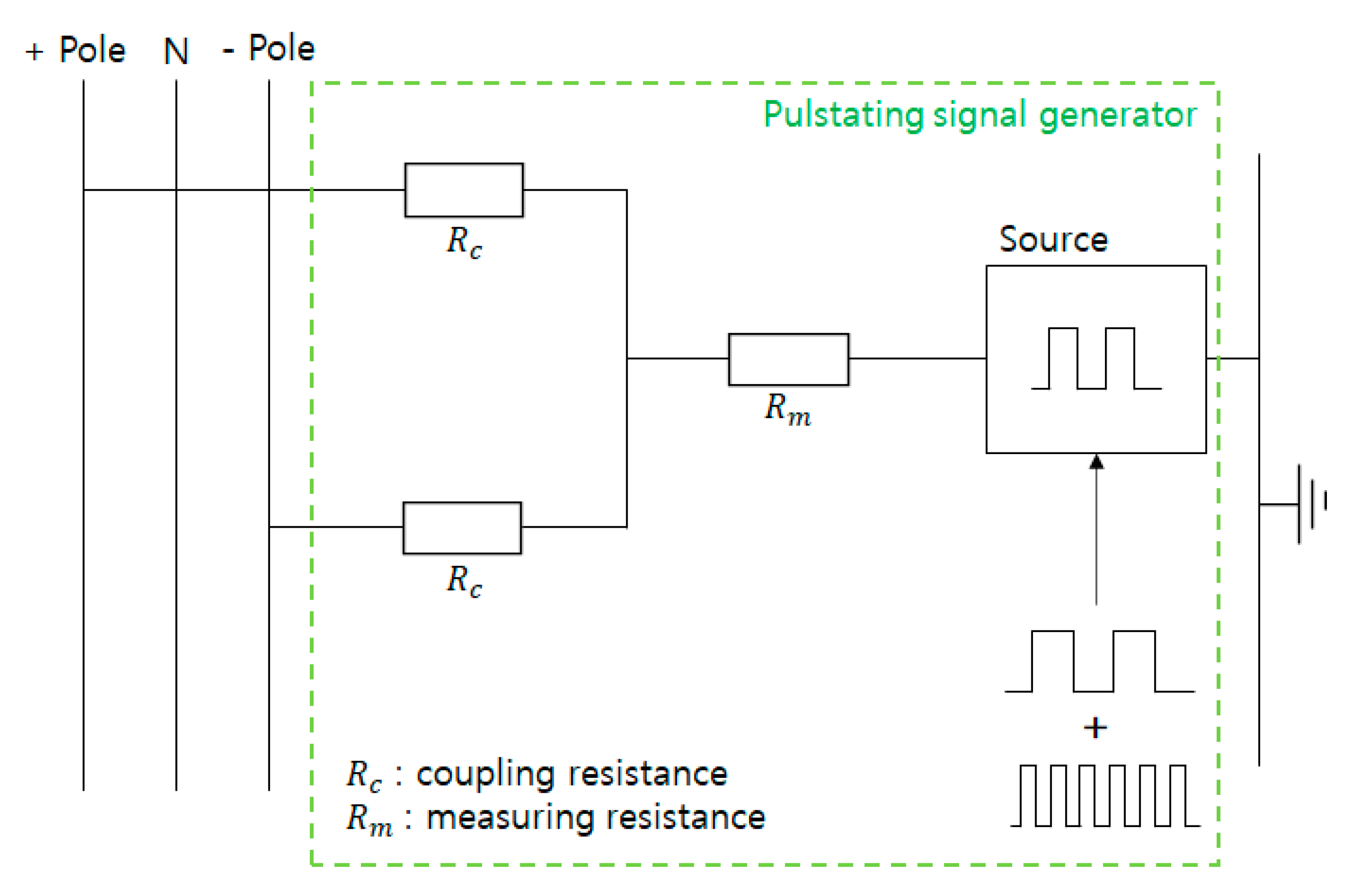
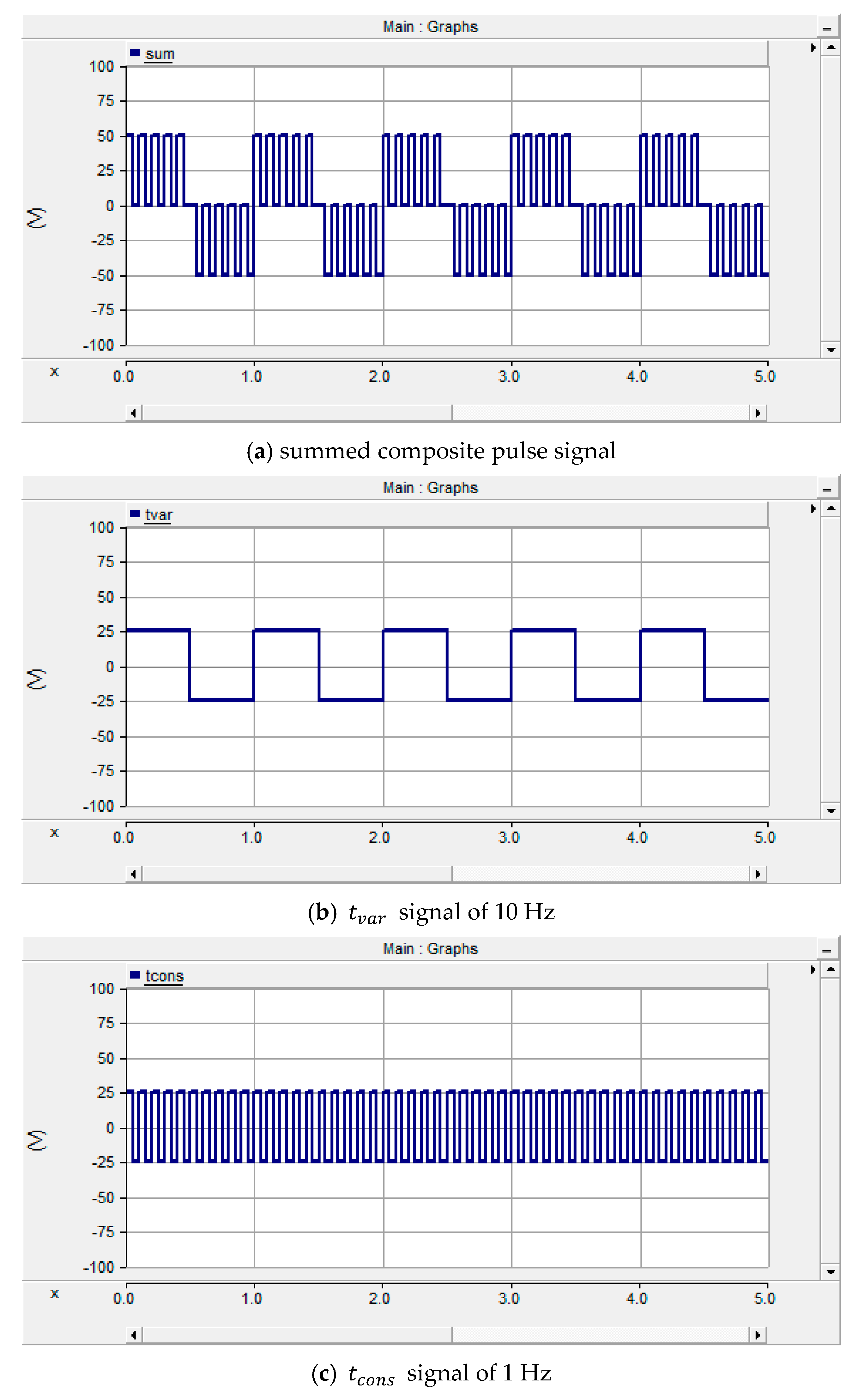
2.1. Principle of the Pulsating Signal Generator
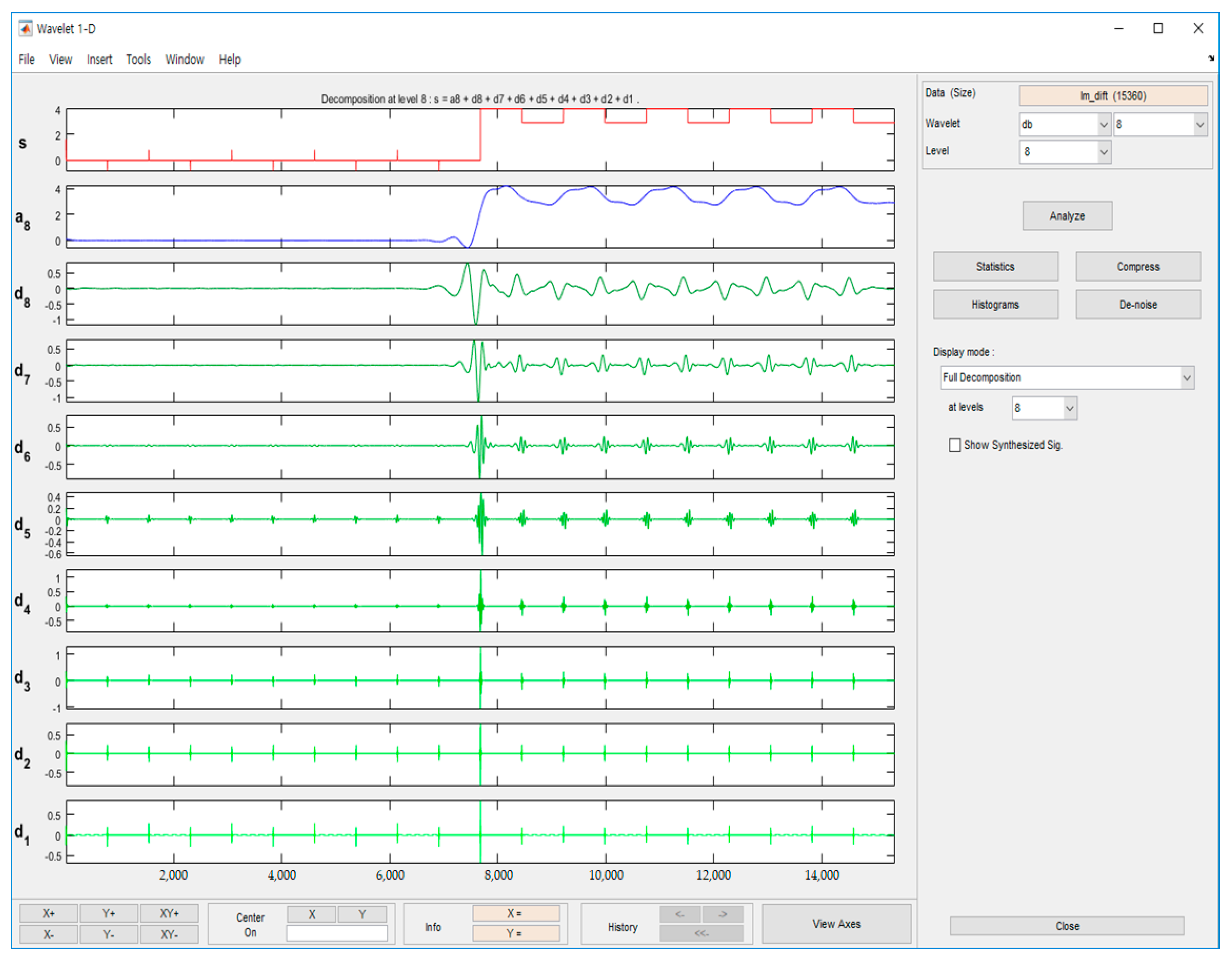
2.2. Discrete Wavelet Transform
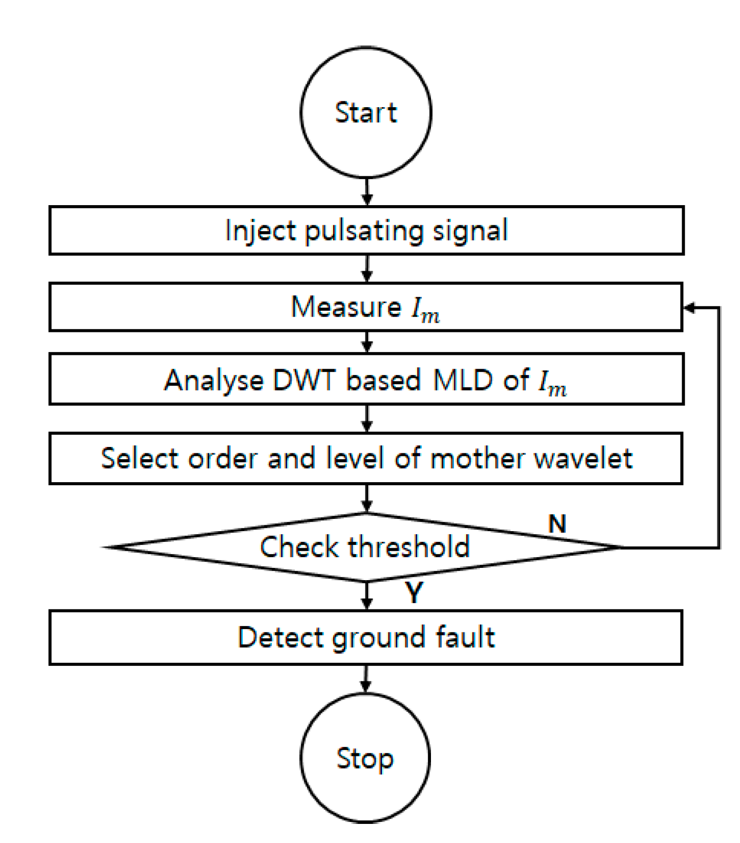
2.3. Ground Fault Detection Hybrid Method Using DWT Based on Pulsating Signal Generator
3. Modeling of LVDC Microgrid and Simulation of the Proposed Hybrid Method
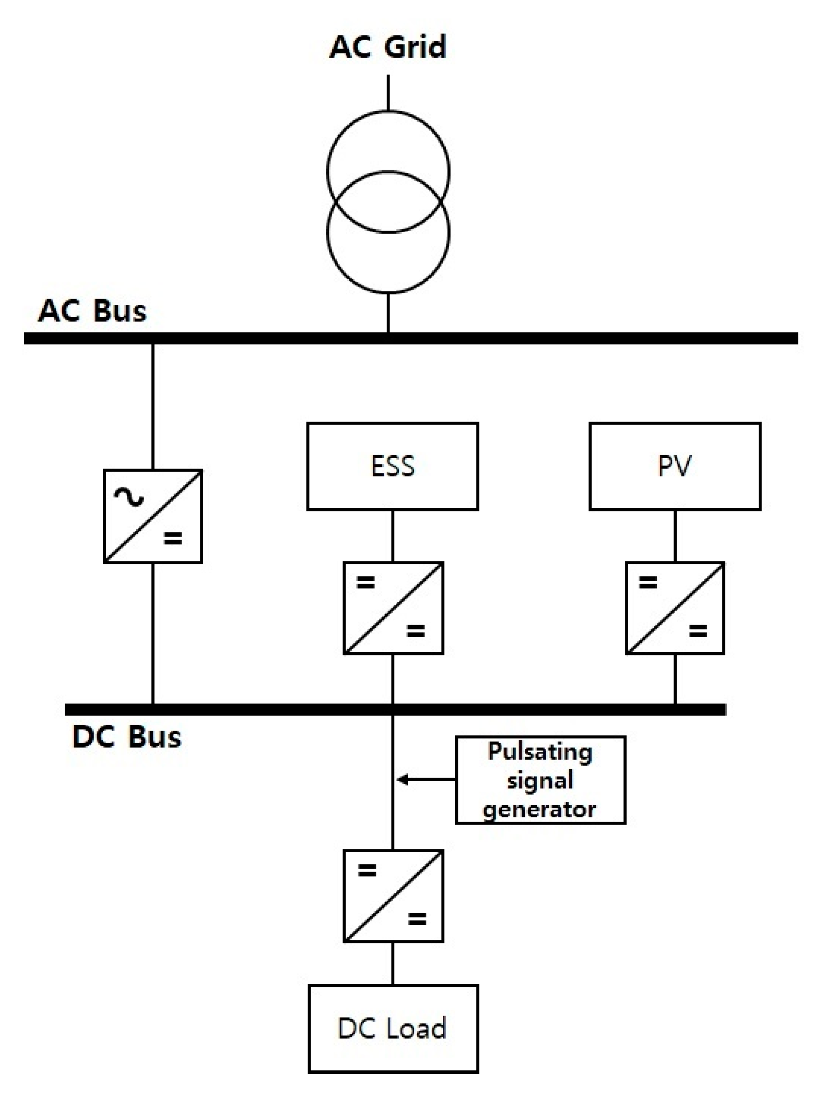
3.1. Modeling of LVDC Microgrid
3.2. Performance Simulation of LVDC Microgrid
PSCAD Modeling of Pulsating Signal Generator
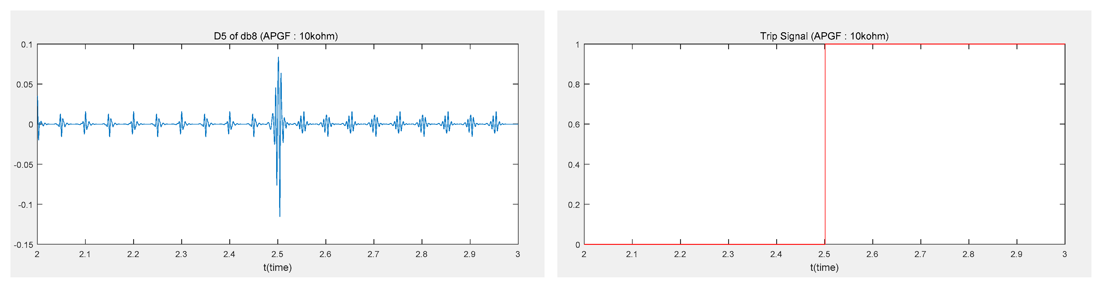
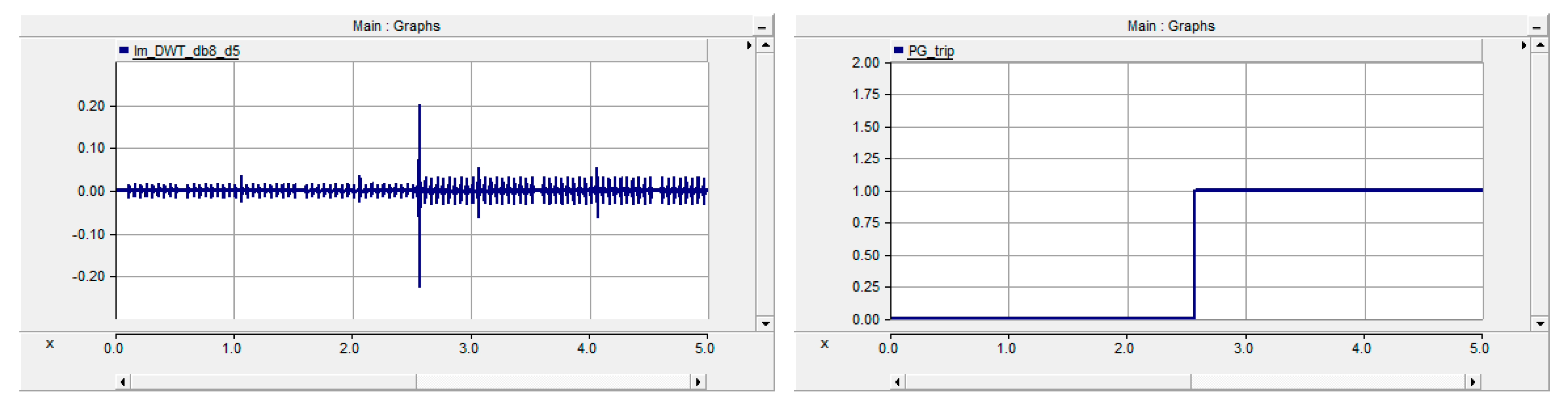
3.3. Simulation and Test of Proposed Ground Detection Hybrid Method Using MATLAB
3.3.1. Ground Fault
3.3.2. Short Fault
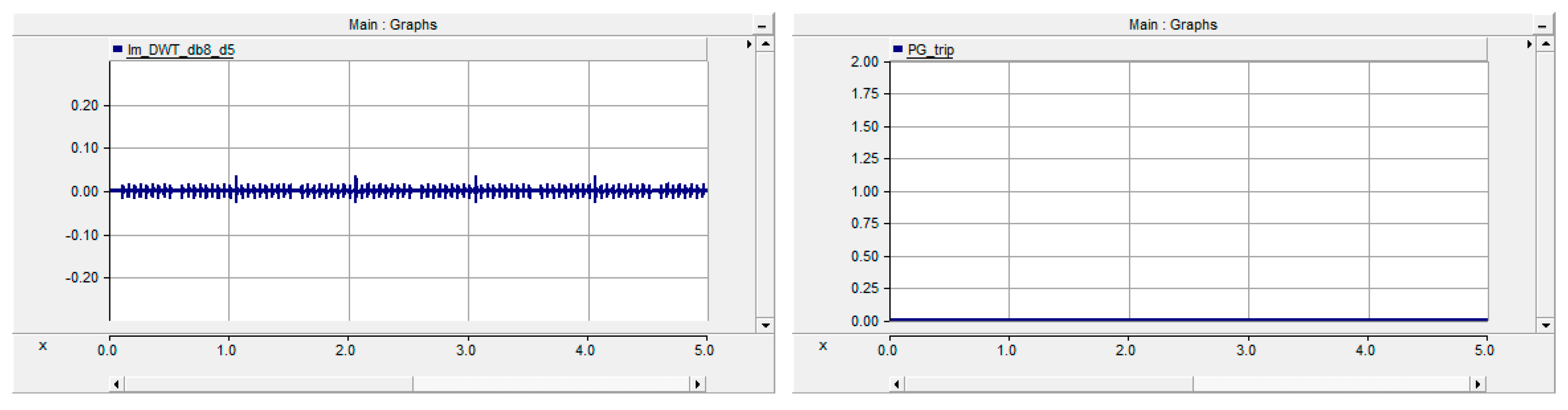
3.3.3. Load Change
4. Comparison of the Conventional and the Proposed Method
5. Conclusions
Author Contributions
Funding
Conflicts of Interest
References
- Cho, J.T. Development and implementation of DC distribution. In Proceedings of the 2018 KIIEE Annual Spring Conference, Gangwon, Korea, 16–18 May 2018; pp. 1–33. [Google Scholar]
- Lee, K.M.; Park, C.W. Performance Verification of the Interconnection Distribution System by PV and BESS. In Proceedings of the 2018 KIEE Electrical Machinery and Energy Conversion Systems Spring Conference, Gangwon, Korea, 19–21 April 2018; pp. 152–154. [Google Scholar]
- Wang, D.; Emhemed, A.; Burt, G.; Norman, P. Fault Analysis of an Active LVDC Distribution Network for Utility Applications. In Proceedings of the 2016 51st International Universities Power Engineering Conference (UPEC), Coimbra, Portugal, 6–9 September 2016. [Google Scholar]
- Carminati, M.; Ragaini, E.; Tironi, E. DC and AC ground fault analysis in LVDC microgrids with energy storage systems. In Proceedings of the 2015 IEEE 15th International Conference on Environment and Electrical Engineering (EEEIC), Rome, Italy, 10–13 June 2015; pp. 1047–1054. [Google Scholar]
- Lee, K.M. A Study on Modeling and Fault Analysis of Low Voltage Direct Current Grid. Master’s Thesis, Gangneung-Wonju National University, Gangwon, Korea, 2017; pp. 1–52. [Google Scholar]
- Lee, K.M.; Park, C.W.; Ahn, T.P. In Proceedings of the High-Speed Circuit Breakers for Low-Voltage DC Distribution System, KEPRI Research Proposal, Gangwon, Korea, 30 June 2016; pp. 1–160.
- Chang, S.Y. LVDC distribution technology trend. In Proceedings of the 2018 KIIEE Annual Spring conference, Gangwon, Korea, 16–18 May 2018; pp. 1–29. [Google Scholar]
- Kim, H.S.; Han, S.Y.; Han, H.S. Development of DC Leakage Current Sensor for Solar Power Generation System. Trans. KIEE 2014, 63, 828–833. [Google Scholar] [CrossRef]
- Hyoek, J.J.; Kim, C.J.; Song, J.I.; Noh, C.H.; Gwon, G.H.; Kim, C.H. Development of Ground Fault Detection Method in Unearthed Low Voltage DC Distribution System using Probe Unit. In Proceedings of the 2016 KIIEE Autumn Conference, Seoul, Korea, 11 November 2016; p. 69. [Google Scholar]
- Jung, J.Y.; Kwon, Y.J. An analysis of protection devices for IT grounding system applied on PCS. In Proceedings of the 2018 24th International Conference on Electrical Engineering, Seoul, Korea, 24–28 June 2018. [Google Scholar]
- Kim, H.J.; Cho, Y.P.; Kim, J.H.; Cho, J.T.; Kim, J.Y. Demonstration of the LVDC distribution system in an island. In Proceedings of the 2017 24th International Conference & Exhibition on Electricity Distribution (CIRED), Glasgow, UK, 12–15 June 2017; pp. 2215–2218. [Google Scholar]
- Karmacharya, I.M. Fault Location in Grid Connected Ungrounded PV Systems Using Wavelets. Master’s Thesis, University of Saskatchewan, Saskatoon, SK, Canada, 2016; pp. 1–138. [Google Scholar]
- Park, J.D. Ground Fault Detection and Location for Ungrounded DC Traction Power Systems. IEEE Trans. Veh. Technol. 2015, 64, 5667–5676. [Google Scholar] [CrossRef]
- Olszowiec, P. Insulation Measurement and Supervision in Live AC and DC Unearthed Systems, 2nd ed.; Springer: Heidelberg, Germany, 2014; pp. 1–180. [Google Scholar]
- Bender. ISOMETER IRDH375. Manual; Bender: Exton, PA, USA, 2017; pp. 1–96. Available online: https://www.bender.de/en/products/insulation-monitoring/isometer_irdh375 (accessed on 20 May 2020).
- ABB. Insulation Monitoring Relays CM-IWN.4/5/6; Data Sheet; ABB: Zurich, Switzerland; pp. 1–20. Available online: https://docs.rs-online.com/2d33/0900766b812cdbf0.pdf (accessed on 20 May 2020).
- Schaefer, O.; Schepp, K. Method and Device for Monitoring the Insulation of Ungrounded DC and AC Voltage Networks. U.S. Patent US9,069,025 B2, 30 June 2015. [Google Scholar]
- Chen, P.; Xu, B.; Li, J. A traveling wave based fault locating system for HVDC transmission lines. In Proceedings of the 2006 International Conference on Power System Technology, Chongqing, China, 22–26 October 2006; pp. 1–4. [Google Scholar]
- Schweitzer, E.O.; Guzmn, A.; Mynam, M.V.; Skendzic, V.; Kasztenny, B.; Marx, S. Locating faults by the traveling waves they launch. In Proceedings of the 2014 67th Annual conference for Protective Relay Engineers, College Station, TX, USA, 31 March–3 April 2014; pp. 95–110. [Google Scholar]
- Alam, M.K.; Khan, F.H.; Johnson, J.; Flicker, J. PV arc-fault detection using spread spectrum time domain reflectometry (SSTDR). In Proceedings of the 2014 IEEE Energy Conversion Congress and Exposition (ECCE), Pittsburgh, PA, USA, 14–18 September 2014; pp. 3294–3300. [Google Scholar]
- Stephane, M. A Wavelet Tour of Signal Processing, 3rd ed.; Academic Press: New York, NY, USA, 2008. [Google Scholar]
- Félix, C.S.; Walter, F.G.; Raúl, G.C.; Stephane, C.D. Multiresolution analysis based on Mallat pyramidal algorithm applied to GPR data. In Proceedings of the 15th International Conference on Ground Penetrating Radar, Brussels, Belgium, 30 June–4 July 2014; pp. 647–650. [Google Scholar]
- Yang, R. The Study of Locating Ground Faults in DC Microgrid Using Wavelet Transform. Master’s Thesis, University of Wisconsin, Milwaukee, WI, USA, 2016. [Google Scholar]
- Karmacharya, I.M.; Gokaraju, R. Fault Location in Ungrounded Photovoltaic System Using Wavelets and ANN. IEEE Trans. Power Deliv. 2018, 33, 549–559. [Google Scholar] [CrossRef]
- IEC International Standard. Electrical Safety in Low Voltage Distribution Systems up to 1000 V a.c. and 1500 V d.c.–Equipment for Testing, Measuring or Monitoring of Protective Measures-Part 8: Insulation Monitoring Devices for IT Systems, IEC 61557-8, 3nd ed.; IEC International Standard: Geneva, Switzerland, 2014; pp. 1–47. [Google Scholar]


| Fault Type | Magnitude in Case of Fault (mA) | Magnitude in Steady State (mA) |
|---|---|---|
| 1 kΩ PtoG | 0.117 | 0.016 |
| 10 kΩ PtoG | 0.118 | 0.015 |
| 50 kΩ PtoG | 0.107 | 0.015 |
| 100 kΩ PtoG | 0.098 | 0.016 |
| 250 kΩ PtoG | 0.079 | 0.015 |
| 500 kΩ PtoG | 0.058 | 0.015 |
| Load change | 0 | 0.015 |
| Fault Type | Conventional Method (S) | Proposed Method (S) |
|---|---|---|
| 10 kΩ PtoG | 0.199 | 0.052 |
| 20 kΩ PtoG | 0.250 | 0.052 |
| 30 kΩ PtoG | 0.298 | 0.052 |
| 40 kΩ PtoG | 0.250 | 0.051 |
| 50 kΩ PtoG | 0.299 | 0.056 |
| 60 kΩ PtoG | 0.299 | 0.056 |
| 70 kΩ PtoG | 0.300 | 0.056 |
| 80 kΩ PtoG | 0.301 | 0.056 |
| 90 kΩ PtoG | 0.400 | 0.056 |
| 100 kΩ PtoG | 0.150 | 0.056 |
© 2020 by the authors. Licensee MDPI, Basel, Switzerland. This article is an open access article distributed under the terms and conditions of the Creative Commons Attribution (CC BY) license (http://creativecommons.org/licenses/by/4.0/).
Share and Cite
Lee, K.-M.; Park, C.-W. Ground Fault Detection Using Hybrid Method in IT System LVDC Microgrid. Energies 2020, 13, 2606. https://doi.org/10.3390/en13102606
Lee K-M, Park C-W. Ground Fault Detection Using Hybrid Method in IT System LVDC Microgrid. Energies. 2020; 13(10):2606. https://doi.org/10.3390/en13102606
Chicago/Turabian StyleLee, Kyung-Min, and Chul-Won Park. 2020. "Ground Fault Detection Using Hybrid Method in IT System LVDC Microgrid" Energies 13, no. 10: 2606. https://doi.org/10.3390/en13102606
APA StyleLee, K.-M., & Park, C.-W. (2020). Ground Fault Detection Using Hybrid Method in IT System LVDC Microgrid. Energies, 13(10), 2606. https://doi.org/10.3390/en13102606