Abstract
To resolve the protection issues caused by high penetration of distributed energy resources, this paper proposes an efficient protection scheme for microgrids based on the autocorrelation of three-phase current envelopes. The proposed strategy uses a squaring and low-pass filtering approach for evaluating the envelope of the current signal. Then, the variance of the autocorrelation function is used to extract the hidden information of the distorted envelope to detect the fault signatures in the microgrid. Furthermore, the reactive power is used for determining the fault direction. The performance of the proposed protection scheme was verified on a standard medium-voltage microgrid by performing simulations in the MATLAB/Simulink environment (Version: R2017b). The proposed scheme was shown to be easy to implement and have good performance under looped and radial configuration for both grid-connected and islanded operation modes. The simulation results showed that the scheme could not only detect, locate, classify, and isolate various types of short-circuit faults effectively but also provide backup protection in case of primary protection failure.
1. Introduction
The utilization of distributed energy resources (DERs) to generate electric power around the world is increasing owing to the increasing cost and gradual depletion of fossil fuels, and the considerably rising demands for clean power and greenhouse gas emission reduction [1,2]. Large scale distributed energy resources are penetrated into the distribution network to form a subnetwork called a microgrid. The microgrid is causing conventional bulk power generation systems to rapidly transform into distributed generation systems [3,4]. It has the capability to provide environmental and economic benefits by supplying power locally, shaving peak loads, reducing line losses, and supplying continuous energy supply with improved reliability and energy efficiency. Nevertheless, the use of the microgrid has several technical challenges owing to its specific characteristics and operation, of which, the major issue is protection [5,6].
The implementation of the microgrid disrupts the safe operation of the conventional protection structure, which is designed assuming large fault currents and unidirectional power flow. However, with the high penetration of distributed generators (DGs) in the microgrid and the ability of the microgrid to switch across grid-connected and islanded modes, the amplitude and direction of fault currents vary according to the system’s irregularities [7]. In both low and medium-voltage generation systems, the bidirectional power arising from the generators and loads flows through the protective devices in a microgrid. During grid-connected operation, the majority of the fault current is contributed by the grid; this results in very high fault currents. On the contrary, during standalone mode of operation, fault currents drop to very low levels owing to the contribution of limited-capacity DERs. Under such varying operating conditions, the fault patterns of the microgrid are not as obvious as in traditional protection systems. Therefore, the standard overcurrent relays used in conventional protection systems are unable to obtain sufficient fault information and take a long time to detect faults, which causes instability issues and damage to the equipment, as well as sensitivity and selectivity problems; furthermore, it makes it difficult to detect and classify disturbances occurring in an islanded microgrid and makes protection more challenging [8,9].
To ensure the efficient and reliable operation of a microgrid, it is highly important to detect and locate faults to restore power with a minimum outage, and to limit damage- and protection-related problems. Therefore, to maintain a high level of continuity of services and satisfaction of customers under both operating modes, fast and intelligent protection strategies have to be designed through advanced signal processing techniques, which can overcome the aforementioned protection challenges. To this end, a protection scheme designed for a microgrid should consider the following aspects: (a) bidirectional power flow, (b) looped feeders, and (c) reduced short-circuit current during islanded operation [10,11].
Several schemes providing solutions to the problems associated with a microgrid have been proposed in the literature. Reference [11] presented a communication-assisted protection scheme based on microprocessor-based relays (MBRs) for a medium-voltage microgrid. The authors in [12] suggested an agent-based method for protection against single-phase earth faults in traditional radial-distribution systems. Reference [13]. described a protection scheme based on a positive-sequence component with a phasor measurement unit and MBRs. By employing a discrete Fourier transform, a data mining–based intelligent differential protection strategy was developed in [14]. The authors in [15] presented a protection scheme based on superimposed reactive energy using the Hilbert transform. Reference [16] proposed a current-differential protection scheme based on positive-sequence fault components for the protection of a distribution network. The authors in [17] proposed a protection technique for isolated microgrids based on communication assisted by inverter-based distribution generation using a data-mining approach. The authors in [18] developed a protection scheme based on microprocessor-based relay for low-voltage microgrid. The authors in [19] proposed an online adaptive overcurrent protection method for automatically updating the settings of an overcurrent relay. Reference [20] proposed an online adaptive multistage definite time overcurrent scheme for ungrounded distribution systems with DGs. The authors in [21] proposed a comprehensive protection strategy employing MBRs for the dependable and safe operation of an islanded microgrid. In [22], a loop-based microgrid protection scheme was proposed to handle various faults in both grid-connected and standalone operating modes. The authors in [23] proposed a differential protection scheme for microgrids using time-frequency transform.
The above-mentioned schemes resolved microgrid-protection problems using different protection aspects. However, each of the scheme has some limitations. Some schemes require dual settings, one for the islanded mode and one for the grid-connected mode, and some are only applicable to either mode. Adaptive schemes involve complex fault calculations for relay settings; thus, they have a high computational burden. Some schemes only consider inverter-interfaced DGs in the microgrid. For overcoming these limitations, herein, we propose a microgrid protection scheme based on the autocorrelation function (ACF) of a three-phase current envelope. In the proposed scheme, the squaring and low-pass filtering method is first employed to extract the current signal envelope. Then, the ACF of the current envelope is computed for each phase to detect the hidden fault information in the microgrid. Next, the variance in the ACF of each phase current is obtained to verify the fault in the microgrid. Once a fault event is established in the microgrid, the fault direction is determined from the reactive power. The scheme is evaluated on a standard medium-voltage microgrid test system using MATLAB/Simulink. The obtained numerical simulation results validate the performance of the proposed scheme. The main contributions of this study are as follows:
- A simple and efficient microgrid protection scheme is proposed based on the squaring and low-pass filtering method and ACF.
- The proposed scheme is easy to implement and does not require complex calculations.
- The scheme is effective under both islanded and grid-connected modes. Therefore, it is not necessary to modify the relay settings when the microgrid changes its modes of operation.
- Backup protection is provided against all types of faults upon a disturbance in primary-protection.
The remainder of this paper is organized as follows. In Section 2, we describe the proposed autocorrelation-based protection strategy for microgrids in detail. In Section 3, we report and discuss the simulation results to validate the performance of the proposed scheme. In Section 4, we present the conclusions of this study.
2. Proposed Microgrid Protection Strategy
This paper presents a microgrid protection strategy that uses the ACF of the three-phase current envelope. Figure 1 shows a schematic of the proposed protection technique. The proposed protection strategy comprises four units: fault detection, fault direction, fault zone identification, and fault classification and tripping units. In the fault detection unit, the squaring and low-pass filtering approach is first employed to extract the envelope of each phase current signal independently. When a fault incident occurs, the envelope of the current signal is significantly disrupted; with the proposed scheme, the ACF is computed from each phase envelope to extract the hidden information in the distorted enveloped signal. In the fault direction unit, reactive power is used to determine the fault direction at a relay point in the microgrid. After the fault detection and fault direction units, the fault zone identification unit identifies the faulty zone through an appropriate operating mechanism. Because the proposed scheme processes each phase current individually, it is inherently phase-segregated. Once the fault information is developed, the classification and tripping units send a trip signal to the appropriate circuit breakers to isolate the faulty section. In the following subsection, we describe the proposed protection scheme in detail.

Figure 1.
Schematic of the proposed protection scheme.
2.1. Fault Detection Unit
Fault detection in microgrids is essential to ensure reliability. The fault detection unit of the proposed scheme employs the squaring and low-pass filtering method, ACF, and variance of the autocorrelation function (VACF) for fault detection in microgrids. These methods are described in detail in the following subsections.
2.1.1. Squaring and Low-Pass Filtering and Envelope Detection
The proposed scheme uses the squaring and low-pass filtering method to determine the envelope of each phase current signal. In this method, the input signal is first squared to effectively demodulate it. Then, if there is no interference of high-frequency components, the input signal is down-sampled directly to reduce the sampling rate; otherwise, a finite-impulse response low-pass filter is used to remove high frequencies, and obtain and smooth the signal envelope at the output. Two additional operations are required to maintain the correct ratio. First, to match the obtained low-frequency signal with the original signal, the signal is amplified by multiplying it by a factor of two. Second, the square root of the signal is taken to eliminate the scale distortion resulting from the squaring of the signal. The advantage of this method is that it is simple and easy to implement [24,25,26,27].
2.1.2. Autocorrelation Function
As discussed previously, in the proposed protection strategy, the fault detection can be verified by the VACF of the phase current envelope. Under normal operating conditions, the variance of the autocorrelation is negligible; however, when a fault occurs, it changes significantly, showing the non-randomness of the signal. Therefore, it can be considered as a fault detection criterion. The autocorrelation of a signal is an index that indicates the changes of a waveform at different time steps. In particular, it is a mathematical expression that extracts the hidden information of any signal and describes the significant changes between a signal and its delayed version over a specific period. It is used in technical analyses to determine the changes in a signal over time. For a finite time, the autocorrelation is typically expressed using finite limits on summation. For N number of samples, it can be expressed as follows:
where is the autocorrelation between two data points that are time steps apart, is the value of the original data set, is the value of the shifted data set, and is the mean of the original data set [27,28,29].
2.1.3. Threshold Setting
To avoid nuisance tripping, the variance of the ACF uses a preset threshold value. If a disturbance is detected in any one of the three phases, and the VACF of the corresponding phase is greater than the threshold value, the output signal increases to a high value and indicates the presence of a fault on that particular line. Determining a suitable threshold value is a crucial task to avoid the false tripping of phases. In this study, we determine the threshold value by performing extensive simulations under worst-case operating conditions. These include the sudden loss of a line, capacitor switching, the sudden loss of a DG, an abrupt load change, and an abrupt 125% overloading of the system. The threshold obtained for fault detection was 0.1 for the test system.
2.2. Fault Direction Unit
The determination of fault direction is a crucial task for microgrid protection. The fault direction must be determined subsequently for a speedy recovery, restoration of the normal operating condition of the microgrid, and to clear a fault quickly with minimum interruption. In this study, the fault direction unit is responsible for the accurate determination of the direction of a fault at the associated relay point. Here, the reactive power is used to determine the fault direction.
2.2.1. Reactive Power
In the proposed protection strategy, the fault direction is determined by the direction of the reactive power, which is calculated as follows:
While determining the fault direction, if the reactive power flows in the positive direction at the fault point, the fault will be considered a forward fault:
If the direction of the reactive power is negative, the fault will be considered a reverse fault:
2.3. Fault Zone Identification Unit
In the proposed scheme, the fault zone identification unit identifies the faulty section. The faulty zone can be determined based on communication among three adjacent relays. Each relay has two protection zones: (1) the main protection zone and (2) the backup protection zone. The relays in the main protection zone operate quickly when a fault occurs in the main protection zone; when a fault occurs in the backup protection zone, they operate after a specific delay. This delay allows the main protective relay of the backup zone to act first. The delay must be greater than that of the main protective relay and its associated circuit breaker. Backup protection is required to enhance the reliability of the power system. The communication delay considered in the proposed scheme is 3 ms [30].
2.3.1. Main and Backup Protection
The efficiency and reliability of the proposed protection scheme can be enhanced using backup protection. For backup protection, a communication link is developed between the protective relays. The fault zone can be recognized by sharing the information of each relay with two other relays by communicating two signals: (i) the fault detection signal SDet and (ii) the fault direction signal SDir. The fault detection signal SDet is 1 when the relay detects a fault and 0 when a no-fault event is detected; the fault direction signal SDir is 1 and 0 when forward and reverse faults are detected, respectively.
Figure 2 shows the fault zone identification process. As shown in the figure, the protective relay MGPRL1 receives SDet and SDir from MGPRH1 and MGPRH2. If the relays MGPRL1 and MGPRH1 detect the fault as a forward fault, the main protection zone will be considered as the faulty zone, and a trip signal Smz(trip) will be generated from the main protection zone. On the contrary, if MGPRL1 detects a forward fault but MGPRH1 detects a reverse fault, MGPRL1 will check the status of MGPRH2. If MGPRH2 confirms a forward fault, the backup zone will be considered the faulty zone, and a trip signal Sbz(trip) with a predetermined delay will be generated from the backup zone. Finally, the forward fault (FF) trip signal is obtained by combining the main and backup protection signals (Smz(trip) and Sbz(trip)) using the OR logic operation.
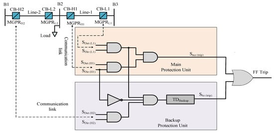
Figure 2.
Main and backup protection principle.
2.4. Fault Classification and Tripping Unit
As explained earlier, the proposed scheme detects faults using the variance of the autocorrelation of each phase individually; thus, it inherently exhibits fault classification capability. Once the fault location and phases are determined, appropriate trip signals for the circuit breakers are generated to isolate the faulty part from the microgrid. On the basis of the predicted output, the trip signal is generated by the relay to isolate the faulty phase.
3. Simulation Results and Discussions
Extensive simulations were performed on an international electro-technical medium-voltage microgrid test system using MATLAB/Simulink to evaluate the performance of the proposed scheme. In this section, the microgrid test system and the microgrid study cases are explained in detail.
3.1. Microgrid Test System
Figure 3 shows the microgrid test system modeled in the MATLAB/Simulink environment. The microgrid distribution network is connected to a base voltage of 25 KV, 15 MVA, and 60 Hz grid at the point of common coupling with a switch, which facilitates the transition between the islanded and grid-connected modes. The system consists of one 2 MW (DGR-2) and two 3 MW (DER-1 and DER-3) inverter interface DGs, as well as one 7 MW synchronous DG (DER-4). Circuit breaker CB loop-1 and circuit breaker CB loop-2 can switch the configuration of the microgrid between looped and radial. It consists of five distributed sections (DL-1, DL-2, DL-3, DL-4, DL-5), with a 20 km line length. The microgrid is interconnected to the main grid through a 120/25 kV Dyn transformer, and each DG source is connected through a 0.630/25 kV transformer.
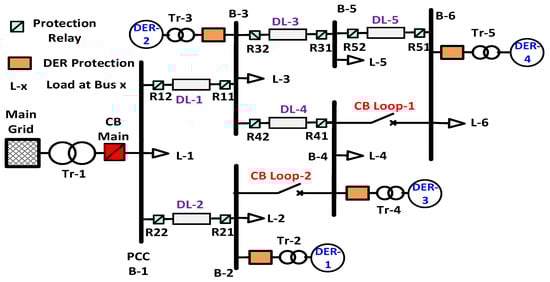
Figure 3.
Test system of the microgrid under study.
3.2. Study Cases
Various types of fault, including single-line-to-ground, line-to-line, double-line-to-ground, and three-phase-to-ground faults, are considered in this study. The looped case is also established by simulating a fault on DL-3 of the test system, and the results are simulated in grid-connected and islanded modes.
3.2.1. Study Case 1: Islanded Mode of Operation
To evaluate the efficiency of the proposed protection strategy, extensive simulations were performed on the microgrid under study in the islanded mode of operation. Here, the simulation results are considered for three-phase-to-ground faults and double-line-to-ground faults. Figure 4 shows the simulation results of the proposed scheme when a three-phase-to-ground fault occurs at DL-5 of the microgrid, and a short-circuit current of approximately 1.5 pu flows through the three phases, as in Figure 4a. From Figure 4b,c, it can be observed that when a fault occurs in the microgrid, the ACF and, hence, VACF, changes significantly and becomes greater than the threshold of 0.1, which indicates the occurrence of a fault in the microgrid. Finally, the positive direction of the reactive power flow at 0.3 s, as observed in Figure 4d, confirms a forward fault in the microgrid. Similarly, when a double-line-to-ground fault occurs at the DL-4, a short circuit current of 1 pu flows through the phases A and B, as shown in Figure 5a. Then, the ACF of the current envelope changes significantly, as shown in Figure 5b. The occurrence of the fault is verified by the VACF, as shown in Figure 5c. Figure 5d shows that the reactive power flow is again in the positive direction at 0.3 s, which confirms the existence of a forward fault in the microgrid.
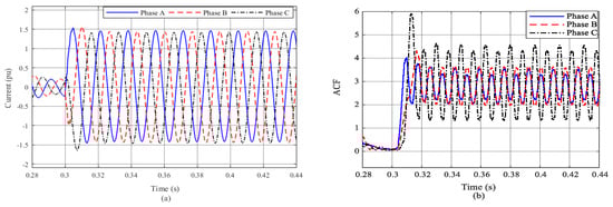
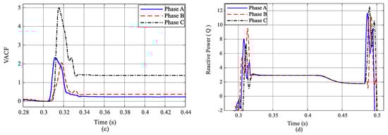
Figure 4.
Three-phase-to-ground fault for islanded microgrid: (a) input current; (b) autocorrelation function (ACF); (c) variance of the autocorrelation function (VACF); (d) reactive power.
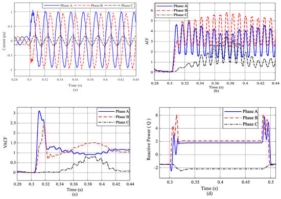
Figure 5.
Double-line-to-ground fault for islanded microgrid: (a) input current; (b) ACF; (c) VACF; (d) reactive power.
3.2.2. Study Case 2: Grid-Connected Mode of Operation
This case study presents the simulation results when the microgrid operates in the grid-connected mode. Here, the simulation results are considered for line-to-line and single-line-to-ground faults. When a line-to-line fault occurs at the DL-1, a short-circuit current flows through lines B and C, as shown in Figure 6a. When a fault occurs in the microgrid, the ACF changes, as shown in Figure 6b. The VACF of the distorted envelope confirms the fault in the microgrid, as shown in Figure 6c. Finally, when the fault is detected, the appropriate direction of the fault can be determined by considering the direction of the reactive power. Figure 6d verifies the presence of a forward fault for a line-to-line fault. Similarly, when a single-line-to-ground fault occurs at DL-3, a short-circuit current flows through phase A of the microgrid, as shown in Figure 7a. The ACF of the envelope signal after fault inception is shown in Figure 7b. The fault detection in the microgrid is confirmed by the VACF, as observed in Figure 7c. Again, the positive direction of reactive power flow at 0.3 s verifies a forward fault in the microgrid, as shown in Figure 7d. The looped case is also considered by simulating a single-line-to-ground fault on DL-3. The results for the looped case are shown in Figure 8.
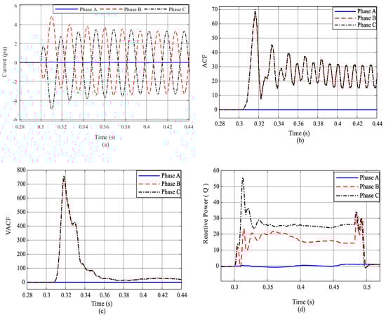
Figure 6.
Line-to-line fault for grid-connected microgrid: (a) input current; (b) ACF; (c) VACF; (d) reactive power.
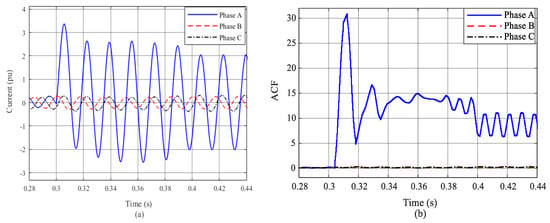
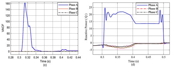
Figure 7.
Single-line-to-ground fault for grid-connected microgrid: (a) input current; (b) ACF; (c) VACF; (d) reactive power.
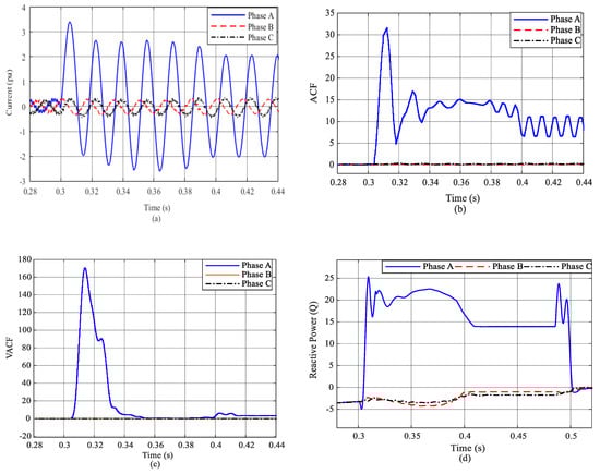
Figure 8.
Single-line-to-ground fault for grid-connected looped microgrid: (a) input current; (b) ACF; (c) VACF; (d) reactive power.
3.2.3. Study Case 3: Primary Protection Failure
In the proposed protection scheme, the primary protection relays detect all faults in the microgrid in a half cycle and takes one cycle to send the trip signal to the relevant circuit breakers to isolate the faults in the microgrid efficiently. From Figure 9, it can be seen that when a single-line-to-ground fault occurs at the DL-3 of the test system, the primary protection isolates the fault within one cycle after the occurrence of the fault in grid-connected mode.
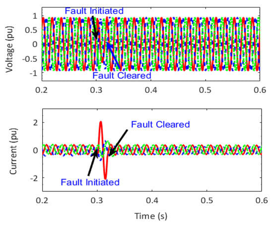
Figure 9.
Primary protection in grid-connected mode.
Although the primary protection isolates all the faults in the microgrid efficiently, to validate the performance of backup protection, the case of primary protection failure is also considered. For the primary protection failure, we simulate the fail operation of R32 when a single-line-to-ground fault occurs at the DL-3 of the microgrid; the results are shown in Figure 10. It is clear from the figure that, after the detection of the fault by the protective relay R31, the primary protection fails to clear the fault, and the fault persists for an additional 0.3 s before being cleared by the backup protection.
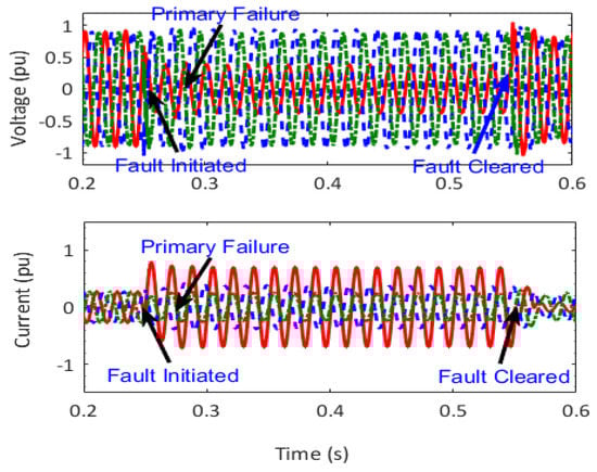
Figure 10.
Backup protection in islanded mode.
In a similar manner, the primary protection failure is considered for the grid-connected mode of operation by simulating a fault on R42 when a three-phase-to-ground fault occurs at DL-4; the results are shown in Figure 11. It is clear from the figure that after the detection of the fault by the protective relay R42, the primary protection fails to clear the fault, and the fault persists for an additional 0.3 s before being cleared by the backup protection.
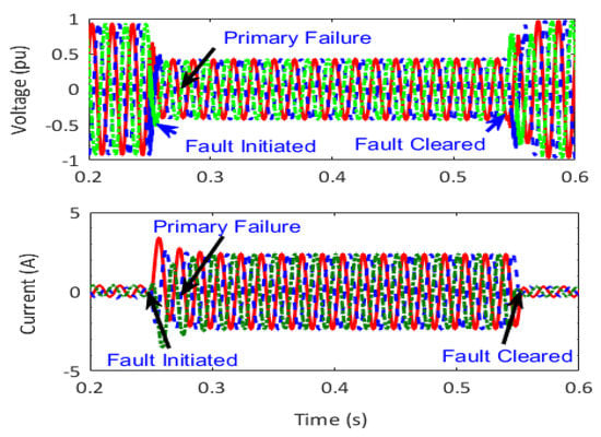
Figure 11.
Backup protection in grid-connected mode.
4. Conclusions
We studied the protection issues of the microgrid and proposed a protection scheme based on the autocorrelation of the three-phase current envelope, which was evaluated using the squaring and low-pass filtering technique. Faults were detected by the variance of the ACF of the distorted envelope, and the reactive power was used for the determination of the fault direction from the relay point. The proposed scheme provided fast and selective tripping by considering the single-phase tripping and offered backup protection in the case of primary protection failure. It was proven to be effective in detecting, locating, classifying, and isolating all types of faults in the microgrid. The proposed scheme showed satisfactory performance and suitability for resolving the issues of microgrid protection in both islanded and grid-connected operation modes.
Author Contributions
S.B. conceptualized the proposed protection scheme and drafted the original article. S.Z.J. and K.K.M. reviewed and edited the first draft. S.B.A.B. provided the resources and valuable comments during the simulation process. M.S.U.Z. and A.H. revised the paper, and the work was carried out under the analysis and supervision of C.-H.K. All authors have read and agreed to the published version of the manuscript.
Funding
This work was supported by the National Research Foundation of Korea (NRF) grant funded by the Korean Government (MSIP) (No.2018R1A2A1A05078680).
Conflicts of Interest
The authors declare no conflict of interest.
References
- Shekar, S.; Kumar, G.; Lalitha, S. Wavelet based transient fault detection and analysis of microgrid connected power system. Int. J. Power Syst. 2016, 1, 46–52. [Google Scholar]
- Chowdhury, S.; Crossley, P. Microgrids and Active Distribution Networks; IET: London, UK, 2009. [Google Scholar]
- Manohar, M.; Koley, E.; Ghosh, S. A reliable fault detection and classification scheme based on wavelet transform and ensemble of SVM for microgrid protection. In Proceedings of the International Conference on Applied and Theoretical Computing and Communication Technology, Tumkur, India, 21–23 December 2017; pp. 24–28. [Google Scholar]
- Wang, Y.; Ravishankar, J.; Phung, T. Wavelet transform-based feature extraction for detection and classification of disturbances in an islanded micro-grid. IET Gener. Transm. Distrib. 2018, 13, 2077–2087. [Google Scholar] [CrossRef]
- Buigues, G.; Dysko, A.; Valverde, V.; Zamora, I.; Fernández, E. Microgrid protection: Technical challenges and existing techniques. In Proceedings of the International Conference on Renewable Energies and Power Quality, Bilbao, Spain, 20–22 March 2013; pp. 222–227. [Google Scholar]
- Lin, X.; Zhang, R.; Tong, N.; Li, X.; Li, M.; Yang, D. Regional protection scheme designed for low-voltage micro-grids. Int. J. Electr. Power Energy Syst. 2015, 64, 526–535. [Google Scholar] [CrossRef]
- Sortomme, E.; Venkata, S.; Mitra, J. Microgrid protection using communication-assisted digital relays. IEEE Trans. Power Deliv. 2010, 25, 2789–2796. [Google Scholar] [CrossRef]
- Mirsaeidi, S.; Said, M.; Mustafa, M.; Habibuddin, M.; Ghaffari, K. An analytical literature review of the available techniques for the protection of micro-grids. Int. J. Electr. Power Energy Syst. 2014, 58, 300–306. [Google Scholar] [CrossRef]
- Saravanababu, K.; Balakrishnan, P.; Sathiyasekar, K. Transmission line faults detection, classification, and location using discrete wavelet transform. In Proceedings of the International Conference on Power, Energy and Control, Dindigul, India, 6–8 February 2013; pp. 233–238. [Google Scholar]
- Mirsaeidi, S.; Said, M.; Mustafa, M.; Habibuddin, M.; Ghaffari, K. Fault location and isolation in micro-grids using a digital central protection unit. Renew. Sustain. Energy Rev. 2016, 56, 1–17. [Google Scholar] [CrossRef]
- Zamani, M.; Yazdani, A.; Sidhu, T.A. Communication-assisted protection strategy for inverter-based medium-voltage microgrids. IEEE Trans. Smart Grid 2012, 3, 2088–2099. [Google Scholar] [CrossRef]
- Wang, Y.; Wei, G.; Yang, H.; Chen, H.; Ouyang, Z. Novel protection scheme of single-phase earth fault for radial distribution systems with distributed generators. IEEE Trans. Power Deliv. 2018, 33, 541–548. [Google Scholar] [CrossRef]
- Mirsaeidi, S.; Said, M.; Mustafa, M.; Habibuddin, M. A protection strategy for microgrids based on positive-sequence components. IET Renew Power Gener 2015, 9, 600–609. [Google Scholar] [CrossRef]
- Kar, S.; Samantaray, S. Data-mining-based intelligent anti-islanding protection relay for distributed generations. IET Gener. Transm. Distrib. 2014, 8, 629–639. [Google Scholar] [CrossRef]
- Bukhari, S.; Zaman, M.; Haider, R.; Oh, Y.-S.; Kim, C.-H. A protection scheme for microgrid with multiple distributed generations using superimposed reactive energy. Int. J. Electr. Power Energy Syst. 2017, 92, 156–166. [Google Scholar] [CrossRef]
- Gao, H.; Li, J.; Xu, B. Principle and implementation of current differential protection in distribution networks with high penetration of DGs. IEEE Trans. Power Deliv. 2017, 32, 565–574. [Google Scholar] [CrossRef]
- Casagrande, E.; Woon, W.; Zeineldin, H.; Svetinovic, D. A differential sequence component protection scheme for microgrids with inverter-based distributed generators. IEEE Trans. Smart Grid 2014, 5, 29–37. [Google Scholar] [CrossRef]
- Zamani, M.; Sidhu, T.; Yazdani, A. A protection strategy and microprocessor-based relay for low-voltage microgrids. IEEE Trans. Power Deliv. 2011, 26, 1873–1883. [Google Scholar] [CrossRef]
- Coffele, F.; Booth, C.; Dyśko, A. An adaptive overcurrent protection scheme for distribution networks. IEEE Trans. Power Deliv. 2015, 30, 561–568. [Google Scholar] [CrossRef]
- Shen, S.; Lin, D.; Wang, H.; Hu, P.; Jiang, K.; Lin, D. An adaptive protection scheme for distribution systems with DGs based on optimized Thevenin equivalent parameters estimation. IEEE Trans. Power Deliv. 2017, 32, 411–419. [Google Scholar] [CrossRef]
- Lai, K.; Illindala, M.; Haj-ahmed, M. Comprehensive protection strategy for an islanded microgrid using intelligent relays. In Proceedings of the IEEE Industry Applications Society Annual Meeting, Dallas, TX, USA, 18–22 October 2015; pp. 1–11. [Google Scholar]
- Liu, X.; Shahidehpour, M.; Li, Z.; Liu, X.; Cao, Y.; Tian, W. Protection scheme for loop-based microgrids. IEEE Trans. Smart Grid 2017, 8, 1340–1349. [Google Scholar] [CrossRef]
- Kar, S.; Samantaray, S. Time-frequency transform-based differential scheme for microgrid protection. IET Gener. Transm. Distrib. 2014, 8, 310–320. [Google Scholar] [CrossRef]
- Bakshi, A. Analog Communication; Technical Publications: Pune, India, 2007. [Google Scholar]
- Khayam, U.; Zaeni, A. Application of squaring—Low pass filtering—Square rooting method for enveloping partial discharge waveform. In Proceedings of the International Conference on Electric Vehicular Technology, Sanur Bali, Indonesia, 2–5 October 2017; pp. 71–75. [Google Scholar]
- Tretter, S. Communication System Design Using DSP Algorithms: With Laboratory Experiments for the TMS320C6713TM DSK; Springer Science & Business Media: Berlin, Germany, 2008. [Google Scholar]
- Haider, R.; Kim, C.-H.; Ghanbari, T.; Bukhari, S.; Zaman, M.; Baloch, S. Passive islanding detection scheme based on autocorrelation function of modal current envelope for photovoltaic units. IET Gener. Transm. Distrib. 2017, 12, 726–736. [Google Scholar] [CrossRef]
- Nounou, M.; Bakshi, B.; Walczak, B. Multiscale methods for denoising and compression. Wavelets Anal. Chem. 2000, 20, 119–150. [Google Scholar]
- Ghanbari, T. Autocorrelation function-based technique for stator turn-fault detection of induction motor. IET Sci. Meas. Technol. 2017, 10, 100–110. [Google Scholar] [CrossRef]
- Bukhari, S.; Haider, R.; Zaman, M.; Oh, Y.-S.; Cho, G.-J.; Kim, C.-H. An interval type-2 fuzzy logic based strategy for microgrid protection. Int. J. Electr. Power Energy Syst. 2018, 98, 209–218. [Google Scholar] [CrossRef]
© 2020 by the authors. Licensee MDPI, Basel, Switzerland. This article is an open access article distributed under the terms and conditions of the Creative Commons Attribution (CC BY) license (http://creativecommons.org/licenses/by/4.0/).