Syngas Production, Clean-Up and Wastewater Management in a Demo-Scale Fixed-Bed Updraft Biomass Gasification Unit

 , , and
Abstract
1. Introduction
2. Materials and Method
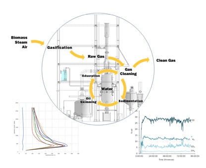
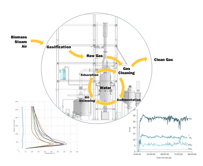
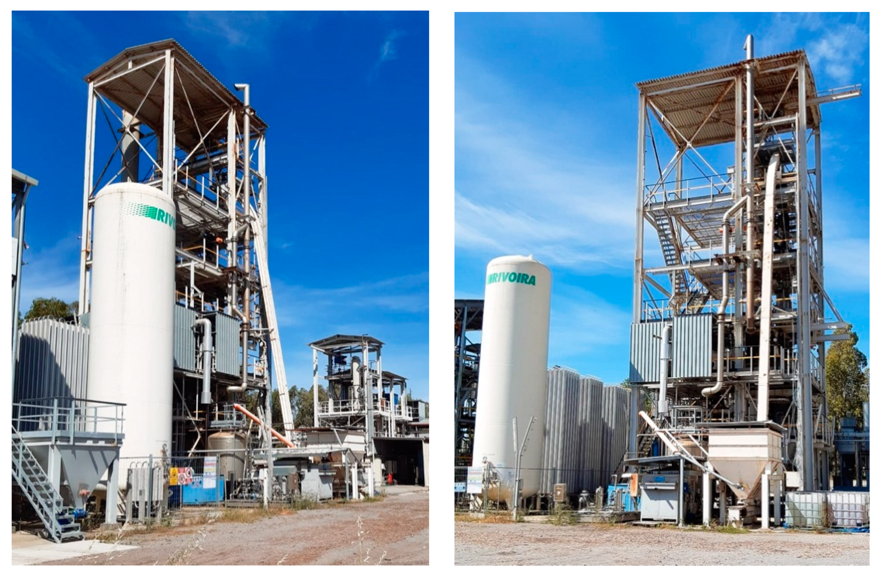
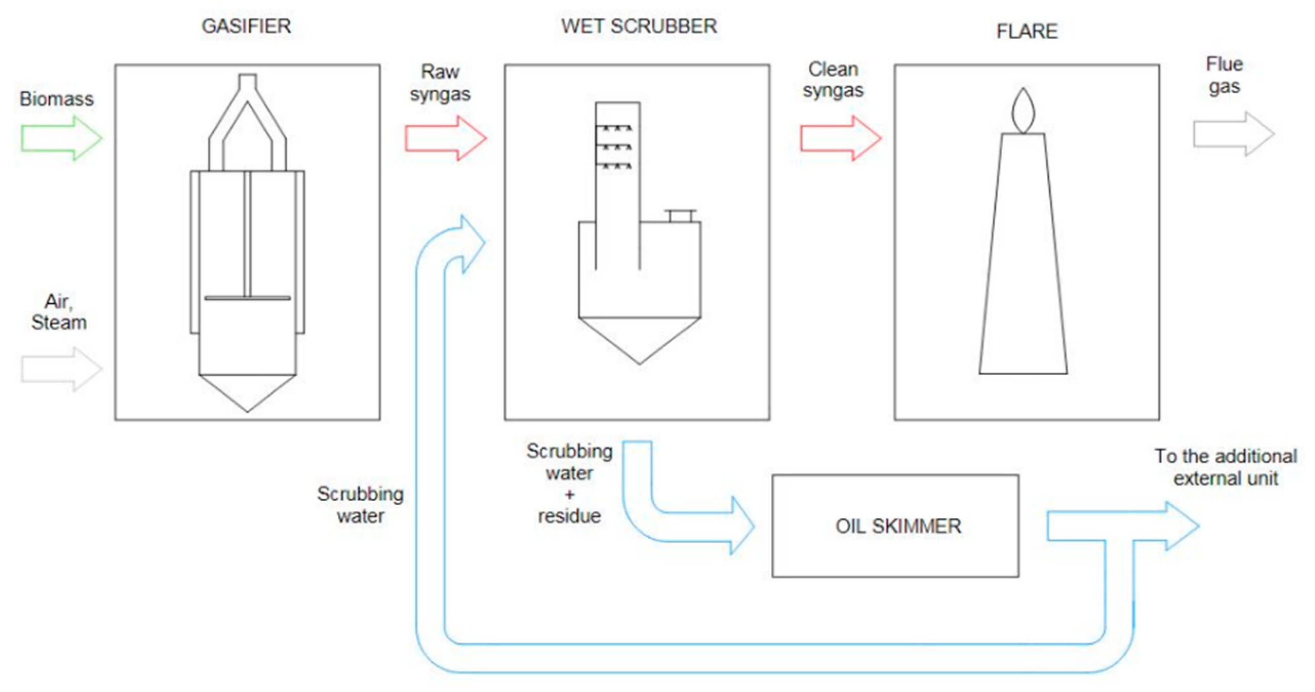
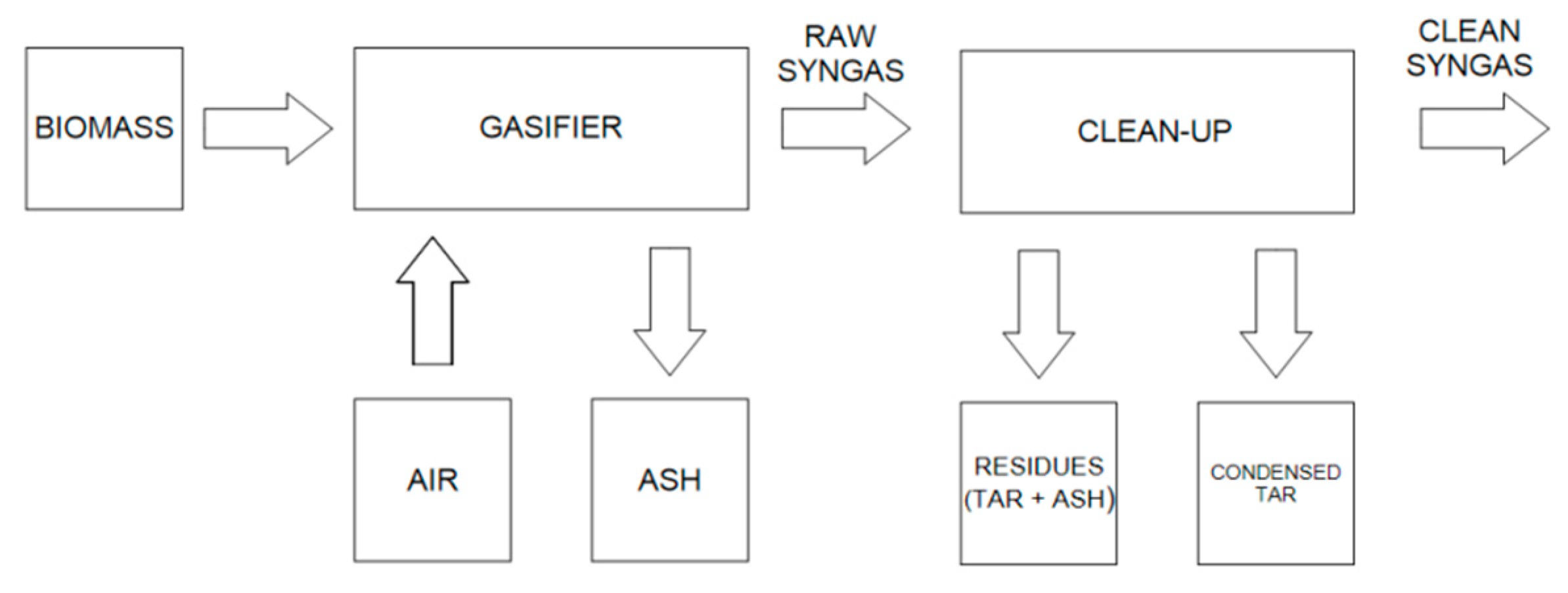
2.1. The Sotacarbo Demonstration-Scale Gasification Unit
2.1.1. Gasification Reactor
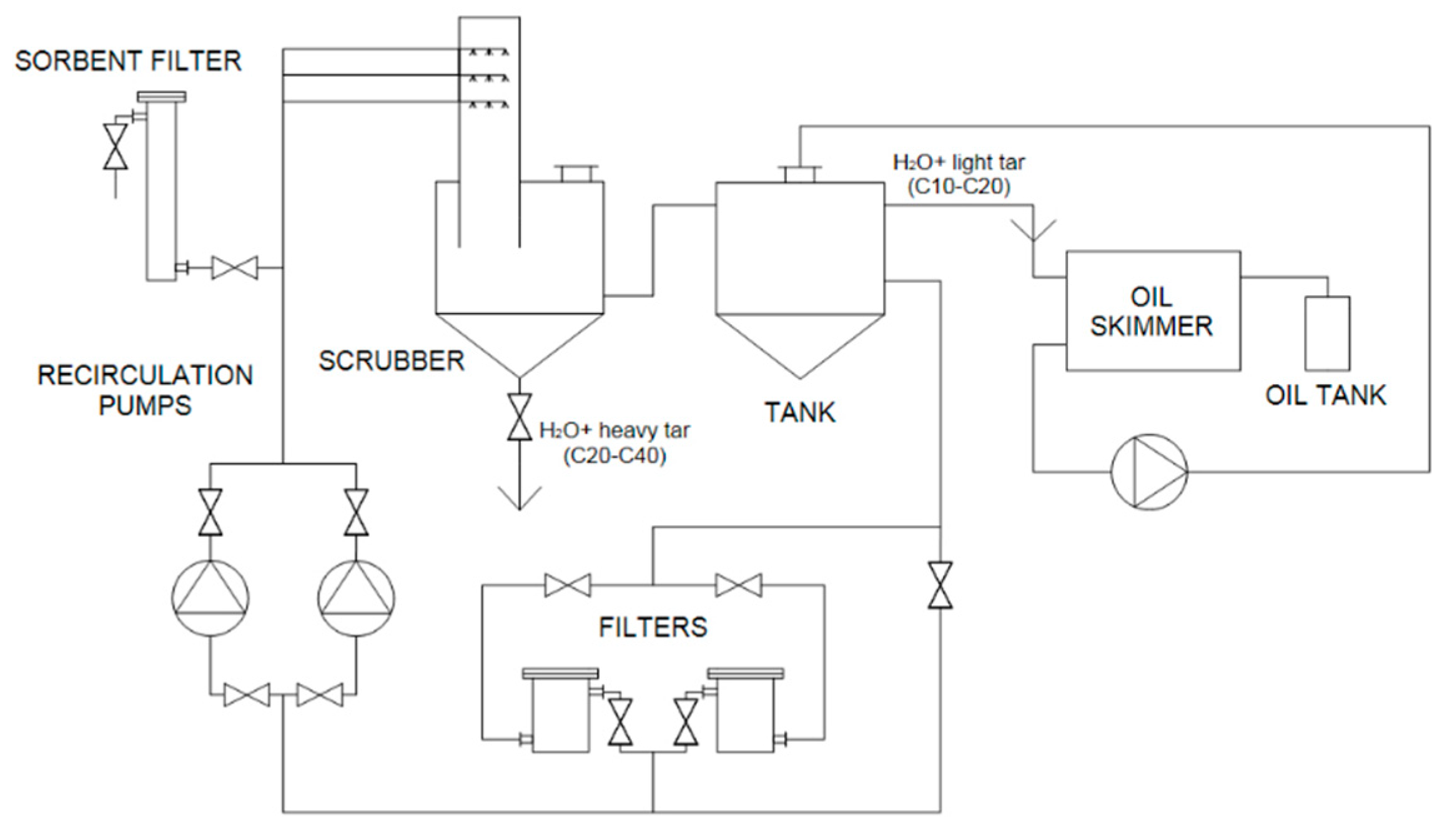
2.1.2. Wet Scrubber
2.1.3. Wastewater Treatment
2.1.4. Auxiliaries
2.2. Primary Fuels
2.3. Experimental Procedures
3. Results and Discussion
3.1. Gasification Performance
3.2. Wastewater Treatment Optimisation and Performance
4. Conclusions
Author Contributions
Funding
Acknowledgments
Conflicts of Interest
References
- International Energy Agency. World Energy Outlook 2019; International Energy Agency: Paris, France, 2019. [Google Scholar]
- European Union. Directive (EU) 2018/2001 of the European Parliament and of the Council of 11 December 2018 on the promotion of the use of energy from renewable sources. Official J. Eur. Union 2018, 61, 82–209. [Google Scholar]
- Krzyzaniak, M.; Stolarski, M.J.; Graban, L.; Lajszner, W.; Kuriata, T. Camelina and crambe oil crops for bioeconomy—Straw utilisation for energy. Energies 2020, 13, 1503. [Google Scholar] [CrossRef]
- Ward, C.; Goldstein, H.; Maurer, R.; Thimsen, D.; Sheets, B.J.; Hobbs, R.; Isgrigg, F.; Steiger, R.; Revay Madden, D.; Porcu, A.; et al. Making coal relevant for small scale applications: Modular gasification for syngas/engine CHP applications in challenging environments. Fuel 2020, 267, 117303. [Google Scholar] [CrossRef]
- Ferreira, S.; Minteiro, E.; Calado, L.; Silva, V.; Brito, P.; Vilarinho, C. Experimental and modeling analysis of brewers’ spent grains gasification in a downdraft reactor. Energies 2019, 12, 4413. [Google Scholar] [CrossRef]
- Marcantonio, V.; Bocci, E.; Monarca, D. Development of a chemical quasi-equilibrium model of biomass waste gasification in a fluidized-bed reactor by using Aspen Plus. Energies 2020, 13, 53. [Google Scholar] [CrossRef]
- Gallucci, F.; Liberatore, R.; Sapegno, L.; Volponi, E.; Venturini, P.; Rispoli, F.; Paris, E.; Carnevale, M.; Colantoni, A. Influence of oxidant agent on syngas composition: Gasification of hazelnut shells through an updraft reactor. Energies 2020, 13, 102. [Google Scholar] [CrossRef]
- Chambon, C.L.; Karia, T.; Sandwell, P.; Hallett, J.P. Techno-economic assessment of biomass gasification-based mini-grids for productive energy applications: The case of rural India. Renew. Energy 2020, 154, 432–444. [Google Scholar] [CrossRef]
- Ren, J.; Liu, J.L.; Zhao, X.Y.; Cao, J.P. Methanation of syngas from biomass gasification: An overview. Int. J. Hydrogen Energy 2020, 45, 4223–4243. [Google Scholar] [CrossRef]
- Szul, M.; Iluk, T.; Sobolewski, A. High-temperature, dry scrubbing of syngas with use of mineral sorbents and ceramic rigid filters. Energies 2020, 13, 1528. [Google Scholar] [CrossRef]
- Situmorang, Y.A.; Zhao, Z.; Yoshida, A.; Abudula, A.; Guan, G. Small-scale biomass gasification systems for power generation (<200 kW class): A review. Renew. Sustain. Energy Rev. 2020, 117, 109486. [Google Scholar]
- Siddiqui, H.; Thengane, S.K.; Sharma, S.; Mahajani, S.M. Revamping downdraft gasifier to minimize clinker formation for high-ash garden waste as feedstock. Bioresour. Technol. 2018, 266, 220–231. [Google Scholar] [CrossRef] [PubMed]
- Sikarwar, V.S.; Zhao, M.; Clough, P.; Yao, J.; Zhong, X.; Memon, M.Z.; Shah, N.; Anthony, E.J.; Fennell, P.S. An overview of advances in biomass gasification. Energy Environ. Sci. 2016, 9, 2939. [Google Scholar] [CrossRef]
- Porcu, A.; Sollai, S.; Marotto, D.; Mureddu, M.; Ferrara, F.; Pettinau, A. Techno-economic analysis of a small-scale biomass-to-energy BFB gasification-based system. Energies 2019, 12, 494. [Google Scholar] [CrossRef]
- Kittivech, T.; Fukuda, S. Investigating agglomeration tendency of co-gasification between high alkali biomass and woody biomass in a bubbling fluidized bed system. Energies 2020, 13, 56. [Google Scholar] [CrossRef]
- Huang, Y.; Zhao, Y.J.; Hao, Y.H.; Wei, G.Q.; Feng, J.; Li, W.Y.; Yi, Q.; Mohamed, U. A feasibility analysis of distributed power plants from agricultural residues resources gasification in rural China. Biomass Bioenergy 2019, 121, 1–12. [Google Scholar] [CrossRef]
- Ren, J.; Cao, J.P.; Zhao, X.Y.; Yang, F.L.; Wei, X.Y. Recent advances in syngas production from biomass catalytic gasification: A critical review on reactors, catalysts, catalytic mechanisms and mathematical models. Renew. Sustain. Energy Rev. 2019, 116, 109426. [Google Scholar] [CrossRef]
- Lee, S.Y.; Park, S.W.; Alam, M.T.; Jeong, J.O.; Seo, Y.C.; Choi, H.S. Studies on the gasification performance of sludge cake pre-treated by hydrothermal carbonization. Energies 2020, 13, 1442. [Google Scholar] [CrossRef]
- Singh Siwal, S.; Zhang, Q.; Sun, C.; Thakur, S.; Gupta, V.K.; Thakur, V.K. Energy production from steam gasification processes and parameters that contemplate in biomass gasifier—A review. Bioresour. Technol. 2020, 297, 122481. [Google Scholar] [CrossRef]
- Hobbs, M.L.; Radulovic, P.T.; Smoot, L.D. Modeling fixed-bed coal gasifier. AIChE J. 1992, 38, 681–702. [Google Scholar] [CrossRef]
- Hahn, O.H.; Wesley, P.D.; Swisshelm, B.A.; Maples, S.; Withrow, J. A mass and energy balance of a Wellman–Galusha gasifier. Fuel Process. Technol. 1979, 2, 332–334. [Google Scholar] [CrossRef]
- Yu, J.; Smith, J.D. Validation and application of a kinetic model for biomass gasification simulation and optimization in updraft gasifiers. Chem. Eng. Process. Process Intensif. 2018, 125, 214–226. [Google Scholar] [CrossRef]
- Mehta, V.; Chavan, A. Physico-chemical treatment of tar-containing wastewater generated from biomass gasification plants. Int. J. Chem. Mol. Eng. 2009, 3, 458–465. [Google Scholar]
- Manek, B.; Javia, M.S.; Harichandan, A.; Ramani, H. A CFD based comprehensive study of coal-fired updraft gasifier in ceramic industry. Therm. Sci. Eng. Prog. 2019, 9, 11–20. [Google Scholar] [CrossRef]
- Murgia, S.; Vascellari, M.; Cau, G. Comprehensive CFD model of an air-blown coal-fired updraft gasifier. Fuel 2012, 101, 129–138. [Google Scholar] [CrossRef]
- Lu, D.; Yoshikawa, K.; Ismail, T.M.; El-Salam, M.A. Assessment of the carbonized woody briquette gasification in an updraft fixed bed gasifier using the Euler-Euler model. Appl. Energy 2018, 220, 70–86. [Google Scholar] [CrossRef]
- Lu, D.; Yoshikawa, K.; Ismail, T.M.; El-Salam, M.A. Computational fluid dynamics model on updraft gasifier using carbonized woody briquette as fuel. Energy Procedia 2017, 142, 166–171. [Google Scholar] [CrossRef]
- James R, A.M.; Yuan, W.; Wang, D.; Wang, D.; Kumar, A. The Effect of Gasification Conditions on the Surface Properties of Biochar Produced in a Top-Lit Updraft Gasifier. Appl. Sci. 2020, 10, 688. [Google Scholar] [CrossRef]
- Lei, M.; Hai, J.; Cheng, J.; Lu, J.; Zhang, J.; You, T. Variation of toxic pollutants emission during a feeding cycle from an updraft fixed bed gasifier for disposing rural solid waste. Chin. J. Chem. Eng. 2018, 26, 608–613. [Google Scholar] [CrossRef]
- Font Palma, C. Modelling of tar formation and evolution for biomass gasification: A review. Appl. Energy 2013, 111, 129–141. [Google Scholar] [CrossRef]
- Devi, J.; Ptasinski, K.J.; Janssen, F.J.J.G. A review of the primary measures for tar elimination in biomass gasification processes. Biomass Bioenergy 2003, 24, 125–140. [Google Scholar] [CrossRef]
- Mahjoub, B.; Jayr, E.; Bayard, R.; Gourdon, R. Phase partition of organic pollutants between coal tar and water under variable experimental conditions. Water Rese. 2000, 34, 3551–3560. [Google Scholar] [CrossRef]
- Ruiz, J.; Juárez, M.; Morales, M.; Muñoz, P.; Mendívil, M. Biomass gasification for electricity generation: Review of current technology barriers. Renew. Sustain. Energy Rev. 2013, 18, 174–183. [Google Scholar] [CrossRef]
- Park, H.I.; Wu, C.J.; Lin, L.S. Coal tar wastewater treatment and electricity production using a membrane-less tubular microbial fuel cell. Biotechnol. Bioprocess Eng. 2012, 17, 654–660. [Google Scholar] [CrossRef]
- Luthy, R.G.; Dzombak, D.A.; Peters, C.A.; Roy, S.B.; Ramaswami, A.; Nakles, D.V.; Nott, B.R. Remediating tar-contaminated soils at manufactured gas plant sites-technological challenges. Environ. Sci. Technol. 1994, 28, 266–276. [Google Scholar] [CrossRef]
- Milne, T.A.; Evans, R.J.; Abatzoglou, N. Biomass Gasifier “Tars”: Their Nature, Formation, and Conversion; Report NREL/TP-570-25357; U.S. National Renewable Energy Laboratory: Golden, CO, USA, 1998. Available online: https://www.nrel.gov/docs/fy99osti/25357.pdf (accessed on 1 October 2019).
- Han, J.; Kim, H. The reduction and control technology of tar during biomass gasification/pyrolysis: An overview. Renew. Sustain. Energy Rev. 2008, 12, 397–416. [Google Scholar] [CrossRef]
- Nyazi, K.; Baçaoui, A.; Yaacoubi, A.; Darmstadt, H.; Adnot, A.; Roy, C. Influence of carbon black surface chemistry on the adsorption of model herbicides from aqueous solution. Carbon 2005, 43, 2218–2221. [Google Scholar] [CrossRef]
- Calí, G.; Deiana, P.; Bassano, C.; Maggio, E. Experimental activities on Sotacarbo 5 MWth gasification demonstration plant. Fuel 2017, 207, 671–679. [Google Scholar] [CrossRef]
- Ghani, M.U.; Radulovic, P.T.; Smoot, L.D. An improved model for fixed-bed coal combustion and gasification: Sensitivity analysis and applications. Fuel 1996, 75, 1213–1226. [Google Scholar] [CrossRef]
- Thimsen, D.P.; Maurer, R.E.; Pooler, A.R.; Pui, D.Y.H.; Liu, B.Y.H.; Kittelson, D.B. Fixed-Bed Gasification Research Using US Coals. Volume 19—Executive Summary. US Bureau of Mines Contract H0222001. 1985. Available online: https://www.osti.gov/servlets/purl/5704367 (accessed on 15 May 2019). [CrossRef]
- De Filippis, P.; Scarsella, M.; de Caprariis, B.; Uccellari, R. Biomass gasification plant and syngas clean-up system. Energy Procedia 2015, 75, 240–245. [Google Scholar] [CrossRef]
- Calí, G.; Deiana, P.; Maggio, E.; Marotto, D.; Mascia, M.; Vacca, A. Management and treatment of the clean-up water from the scrubber of a coal and biomass gasification plant: An industrial case study. Chem. Eng. Trans. 2019, 74, 337–342. [Google Scholar]
- Conte, L.; Falletti, L.; Zaggia, A.; Milan, M. Polyfluorinated organic micropollutants removal from water by ion exchange and adsorption. Chem. Eng. Trans. 2015, 43, 2257–2262. [Google Scholar]
- Liu, Z.Q.; You, L.; Xiong, X.; Wang, Q.; Yan, Y.; Tu, J.; Cui, Y.H.; Li, X.Y.; Wen, G.; Wu, X. Potential of the integration of coagulation and ozonation as a pretreatment of reverse osmosis concentrate from coal gasification wastewater reclamation. Chemosphere 2019, 222, 696–704. [Google Scholar] [CrossRef] [PubMed]


| Parameter | Stone Pine (1) | Stone Pine (2) | Eucalyptus (1) | Eucalyptus (2) | Standard |
|---|---|---|---|---|---|
| Proximate analysis (% by weight) | |||||
| Fixed carbon | 22.33 | 21.09 | 15.37 | 15.67 | By difference |
| Volatiles | 61.87 | 66.91 | 56.09 | 57.41 | ASTM D 5142-04 |
| Moisture | 11.93 | 9.25 | 26.86 | 25.76 | ASTM D 5142-04 |
| Ash | 2.87 | 2.75 | 1.68 | 1.16 | ASTM D 5142-04 |
| Ultimate analysis (% by weight) | |||||
| Total carbon | 50.72 | 50.88 | 49.62 | 49.75 | ASTM D 5373-02 |
| Hydrogen | 6.32 | 6.71 | 6.17 | 6.54 | ASTM D 5373-02 |
| Nitrogen | 0.63 | 0.50 | 0.48 | 0.35 | ASTM D 5373-02 |
| Oxygen | 27.53 | 29.91 | 15.19 | 16.54 | By difference |
| Moisture | 11.93 | 9.25 | 26.86 | 25.76 | ASTM D 5142-04 |
| Ash | 2.87 | 2.75 | 1.68 | 1.16 | ASTM D 5142-04 |
| Other properties | |||||
| LHV (MJ/kg) | 16.07 | 16.08 | 13.12 | 13.34 | |
| Bulk density (kg/dm3) | 0.20 | 0.22 | 0.25 | 0.26 | |
| Parameter | Stone Pine (1) | Stone Pine (2) | Eucalyptus (1) | Eucalyptus (2) |
|---|---|---|---|---|
| Operating parameters | ||||
| Fuel loading (kg/h) | 280 | 275 | 345 | 340 |
| Air flow (kg/h) | 630 | 620 | 655 | 650 |
| Equivalence ratio (%) | 33.02 | 32.85 | 26.48 | 26.36 |
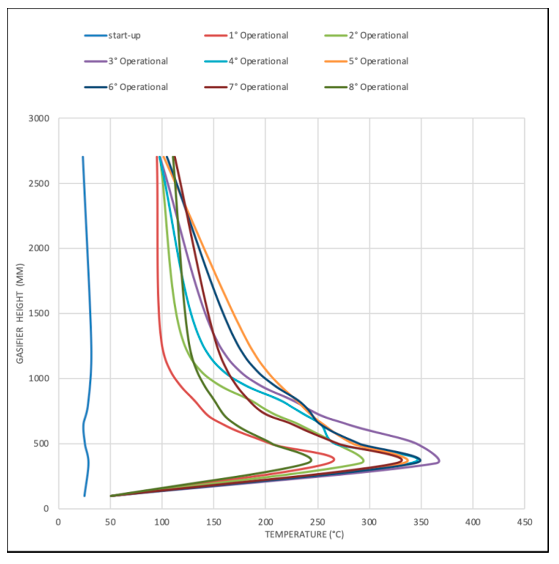
| Fuel bed level (mm) | 1800 | 1800 | 1800 | 1800 |
| Maximum temperature (°C) | 870 | 880 | 830 | 824 |
| Freeboard temperature (°C) | 380 | 376 | 300 | 310 |
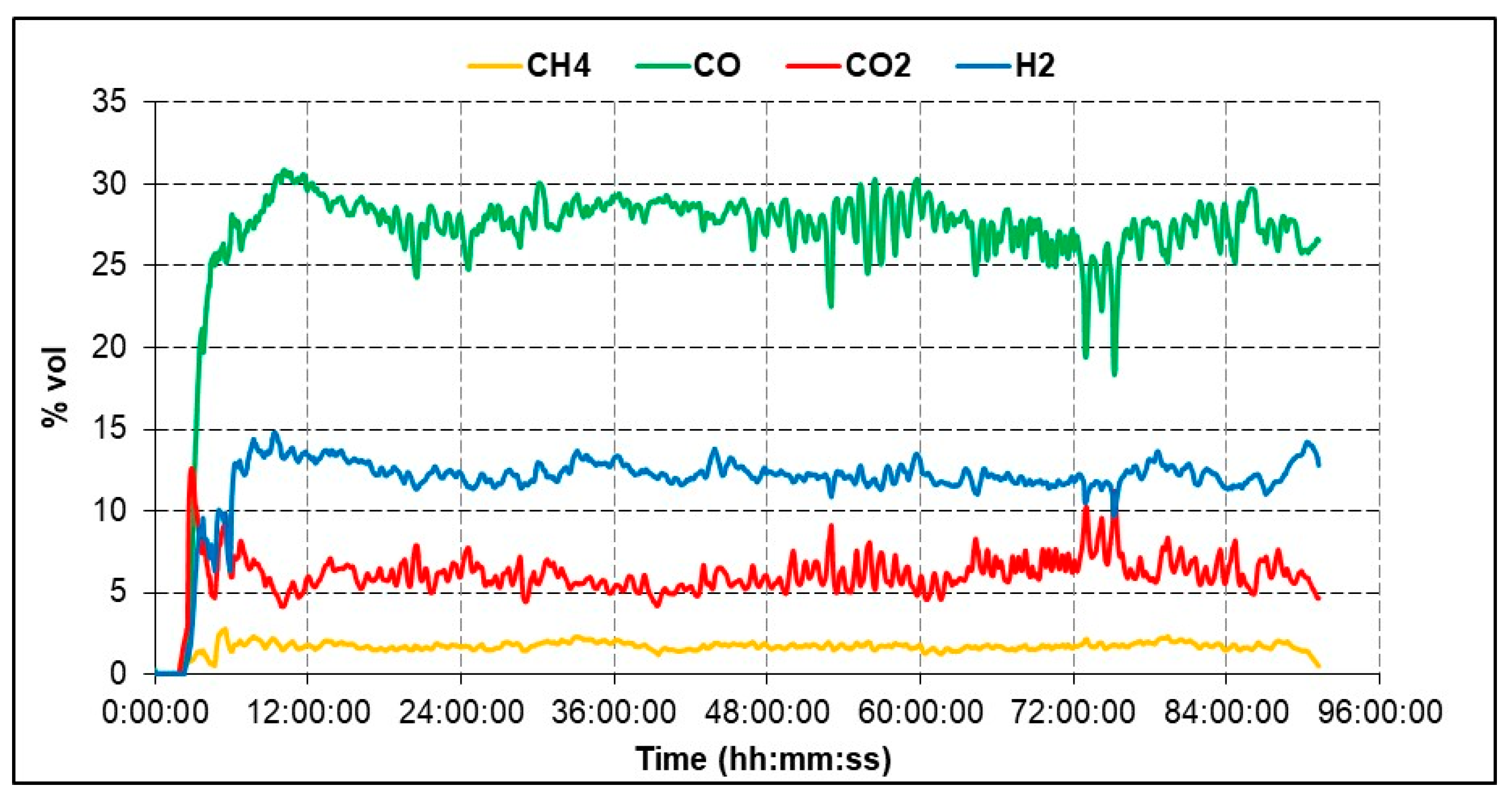
| Syngas composition (molar fraction, dry basis) | ||||
| CO | 0.29 | 0.29 | 0.27 | 0.28 |
| CO2 | 0.05 | 0.05 | 0.06 | 0.06 |
| H2 | 0.12 | 0.12 | 0.12 | 0.12 |
| CH4 | 0.02 | 0.02 | 0.02 | 0.02 |
| H2S | 0.00 | 0.00 | 0.00 | 0.00 |
| N2 | 0.52 | 0.52 | 0.53 | 0.52 |
| Syngas properties and process performance | ||||
| Syngas mass flow (kg/h) | 860 | 845 | 918 | 910 |
| Syngas mass flow (kg/h, dry) | 783 | 772 | 839 | 832 |
| Lower heating val. (MJ/kg, dry) | 4.58 | 4.58 | 4.29 | 4.29 |
| Specific heat (kJ/(kg·K)) | 1.11 | 1.11 | 1.12 | 1.12 |
| Cold gas efficiency | 0.797 | 0.800 | 0.795 | 0.787 |
| Byproducts | ||||
| Tar production (kg/h) | 50 | 45 | 80 | 92 |
| Ash production (kg/h) | 5.5 | 7.0 | 5.0 | 5.4 |
| Parameter | Bottom Ash | Liquid Residues | Condensed Tar |
|---|---|---|---|
| Fixed carbon | 0.14 | n.a. | n.a. |
| Volatiles | 18.66 | 0.00 | 0.00 |
| Moisture | 0.13 | 30.00 | 20.00 |
| Tars (C10–C40) | 68.00 | 80.00 | |
| Minerals | 81.08 | 2.00 | 0.00 |
| Lower heating value (MJ/kg, dry basis) | n.a. | 26.00 | 22.00 |
| Parameter | Raw AC | Exhaust AC | ||
|---|---|---|---|---|
| As Received | Dry Basis | As Received | Dry Basis | |
| Fixed carbon | 79.07 | 82.03 | 56.08 | 79.80 |
| Volatiles | 2.89 | 3.00 | 6.60 | 9.40 |
| Moisture | 3.62 | 0.00 | 29.75 | 0.00 |
| Ash | 14.43 | 14.97 | 7.58 | 10.80 |
| Lower heating value (MJ/kg, dry basis) | 26.39 | n.a. | 18.47 | n.a. |
© 2020 by the authors. Licensee MDPI, Basel, Switzerland. This article is an open access article distributed under the terms and conditions of the Creative Commons Attribution (CC BY) license (http://creativecommons.org/licenses/by/4.0/).
Share and Cite
Calì, G.; Deiana, P.; Bassano, C.; Meloni, S.; Maggio, E.; Mascia, M.; Pettinau, A. Syngas Production, Clean-Up and Wastewater Management in a Demo-Scale Fixed-Bed Updraft Biomass Gasification Unit. Energies 2020, 13, 2594. https://doi.org/10.3390/en13102594
Calì G, Deiana P, Bassano C, Meloni S, Maggio E, Mascia M, Pettinau A. Syngas Production, Clean-Up and Wastewater Management in a Demo-Scale Fixed-Bed Updraft Biomass Gasification Unit. Energies. 2020; 13(10):2594. https://doi.org/10.3390/en13102594
Chicago/Turabian StyleCalì, Gabriele, Paolo Deiana, Claudia Bassano, Simone Meloni, Enrico Maggio, Michele Mascia, and Alberto Pettinau. 2020. "Syngas Production, Clean-Up and Wastewater Management in a Demo-Scale Fixed-Bed Updraft Biomass Gasification Unit" Energies 13, no. 10: 2594. https://doi.org/10.3390/en13102594
APA StyleCalì, G., Deiana, P., Bassano, C., Meloni, S., Maggio, E., Mascia, M., & Pettinau, A. (2020). Syngas Production, Clean-Up and Wastewater Management in a Demo-Scale Fixed-Bed Updraft Biomass Gasification Unit. Energies, 13(10), 2594. https://doi.org/10.3390/en13102594