Article

Small Vessel with Inboard Engine Retrofitting Concepts; Real Boat Tests, Laboratory Hybrid Drive Tests and Theoretical Studies

by
Wojciech Leśniewski
,
Daniel Piątek
,
Konrad Marszałkowski
and
Wojciech Litwin
*
Faculty of Ocean Engineering and Ship Technology, Gdansk University of Technology, ul. Narutowicza 11/12, 80-233 Gdansk, Poland
*
Author to whom correspondence should be addressed.
Energies 2020, 13(10), 2586; https://doi.org/10.3390/en13102586
Submission received: 22 April 2020 / Revised: 11 May 2020 / Accepted: 14 May 2020 / Published: 20 May 2020
(This article belongs to the Section E: Electric Vehicles)

Abstract

:
The development of modern technologies and their increasing availability, as well as the falling costs of highly efficient propulsion systems and power sources, have resulted in electric or hybrid propulsions systems’ growing popularity for use on watercraft. Presented in the paper are design and lab tests of a prototype parallel hybrid propulsion system. It describes a concept of retrofitting a conventionally powered nine meter-long vessel with the system, and includes results of power and efficiency measurements, as well as calculations of the vessel’s operating range under the propulsion of its electric motor. The concept of adding of a solar panels array was studied.

1. Introduction

Environmental protection is currently one of the absolute top criteria in numerous countries around the world. Legal limitations, as well as rising public awareness, result in a growing interest on the part of watercraft owners in electric propulsion systems characterised by increasingly stringent “zero-emission” levels. Intensive research and development activity has also been initiated by scientists from all over the globe, who concentrate on the subjects of hybrid propulsion [1,2], energy management [3,4,5,6], energy efficiency [7,8,9] and effective sources of power [10,11,12,13,14,15,16]. The energy efficiency means consuming less energy by a propulsion system to perform the same ship speed—that is, reducing energy losses. Energy efficiency brings a variety of benefits: reducing greenhouse gas emissions, reducing demand for energy and lowering costs of ship service. These efforts, which are aimed at obtaining the ideal goal of a “zero-emission” ship, also result in implementing other technologies that allow, among other benefits, limiting the use of petroleum-based lubricants [16,17,18] and fuels [18,19] in both large commercial and small recreational vessels.
The recently witnessed dynamic development of electric propulsion and energy storage technological solutions, as well as their falling cost, have resulted in growing public and commercial interest [19,20,21,22,23,24]. Only 10 years ago, most yacht manufacturers claimed that the costs of eco-friendly propulsion systems were too high and that the market was not ready for such products. This opinion stemmed from the fact that their price was well beyond the means of the average sailing or motor yacht buyer. However, research carried out last year by one of the leading luxury yacht manufacturers indicates that today, many customers would give serious consideration to purchasing a vessel equipped with a hybrid diesel-electric or fully electric propulsion system.
There is also the viewpoint that, similar to the passenger car market, in the case of watercraft, extending the product’s life-span means creating less stress on the natural environment than is generated by disposing of an old unit and constructing a new one. Of course, having a positive impact on the environment does not automatically mean a favourable effect on the labour market or the economy.
In the case of passenger cars, it is usually quite difficult to modernize the existing propulsion system to limit exhaust emissions. However, there are numerous well-known cases of replacing combustion engines with electric motors or increasing the capacity of batteries installed in hybrid-powered cars, usually carried out by small, specialized firms. However, such modifications may frequently pose a danger to other traffic participants.
In the shipbuilding sector, the situation is quite different. Large ships supervised by classification societies must meet an entire multitude of rigorous standards pertaining to, among other things, the composition of combustion engine emissions, especially regarding sulphur and nitrogen compounds and particulate matter emissions. The cost of modernizing a large engine room by installing an exhaust gas emission cleaning system runs into hundreds of thousands of euros.
The situation for smaller ships or yachts is similar, even though these watercraft are incomparably smaller and, therefore, the costs of modernization are lower. Their specific character traits, such as frequently more spacious engine rooms and customization—the possibility of a single vessel having propulsion systems from various manufacturers depending on a customer’s preferences, quite often result in the possibility of performing vessel propulsion modifications at low workload expenditures. These can be carried out in succession over several years, with the main cost of modernization consisting of the equipment itself. Long before large companies started to supply certified components for installation on yachts, scores of amateur pioneers were already installing various propulsion systems originating from a wide range of machines and vehicles.

2. Concept of Design and Research Works

Both in Poland and throughout Europe, there are hundreds of medium-sized motor yachts and fishing cutters in operation. As an example, one can point to the Swedish made Aramis 30 series yachts and the very similar Polish-made Conrad-900 series (Figure 1), which have been in production since the 1980s. The boat is 9.10 m by 3.00 m and serves various functions, such as passenger transport, underwater works support vessel, tourism, fishing, a general-purpose working boat for angling, servicing ports, regattas etc. It has proved itself to be a solid rescue boat and handles rough conditions and high waves very well. The vessel has earned the reputation of being very safe and perhaps this is why it is still being produced and sold after so many years.
The Faculty of Ocean Engineering and Ship Technology at the Gdansk University of Technology has such a boat at its disposal and employs it for training and support functions while performing scientific research. The basic specifications of the vessel are presented below (Table 1).
The design and research team had already worked on designing and testing various types of hybrid propulsion systems [25,26,27,28]. Therefore, during design work on the new parallel hybrid drive, a decision was made to install the drive on an existing watercraft unit, so valuable operational data could be collected in the future. The vessel described above was selected for that purpose.
The ship hull resistance vs. speed characteristic is a key parameter that plays a decisive role in power demand, therefore, in energy stored in the batteries as well. Usually, it is determined from model tests conducted at a given scale in a towing tank. The power demand may also be forecast by performing rather sophisticated numerical calculations, which are usually done using advanced software provided by leading companies. Each of these methods has advantages and shortcomings.
In the analysed case, it was decided to carry out the tests on a real vessel by towing the Conrad-900 behind a motorboat. This method also presents certain limitations and is burdened by a certain amount of error stemming from, among other things, the difficulty of maintaining the same course with the two vessels. The error is estimated to be in the neighbourhood of 5%.
The tests were performed on a large lake in windless weather, which roughly corresponds to model tests conducted in a towing tank in calm water. The results, converted into towing power, are presented below (Figure 2).
It should be noted that the power demand depends on the quality and efficiency of components used in the propulsion system, i.e., motor or engine, reduction gear, shaft line with bearings and sealings, and propeller. From practical experience, due to the propeller efficiency rarely exceeding 55%, the shaft’s power should be twice as high as the towing power. After accounting for the efficiency of the electric motor and the power transmission system, it frequently turns out that the demand for electric power is three times larger than the towing power. Therefore, to determine realistic energy demand, it was necessary to conduct the measurements and calculation presented below.

3. Design of the Hybrid Propulsion System

The essence of the proposed concept of modernizing the propulsion system was to retrofit a typical shaft line used on small ships (Figure 1), turning it into a new, compact propulsion system consisting of a 40 kW serial production combustion diesel engine (Figure 3-Element 1), and a manufacturer-assembled power transmission system consisting of a reduction gear with reverse (4) and a bottom reduction gear (5). In the retrofitted propulsion system, a specially designed and constructed clutch and belt drive control module (3) and an electric machine with double motor or generator function (2) were installed between the combustion engine (1) and the gear with reverse (4).
A 3-phase, low speed, AC motor with permanent magnets powered at 48 V using a dedicated controller was used in the modernized propulsion system. It is made by a leading manufacturer whose products had already been used on various types of small watercraft. The electric motor was subjected to tests that formed the basis for preparing the power and efficiency diagram presented below (Figure 4). The conducted measurements indicate that under high load, the motor and its controller work with less than 85% efficiency. With a decrease in load, the efficiency falls slightly. The electric motor is protected against overload. Upon reaching the threshold power, the control system automatically reduces the rotational speed. In performing the demand calculations for propulsion power and energy demand, the combined efficiency of the motor and the controller was assumed to be 80%, which is the lowest value recorded during the tests (Figure 4).
The belt drive design made use of experimental findings, in which various types of belt drives produced by leading manufactures were investigated, with tests performed on a classic straight tooth synchronous belt, bevel belts (herringbone belt) and a classic a set of V-belts. The measurements confirmed that the highest efficiency and minimum noise emissions of 75 dB or less characterized the modern V-belt (Figure 5), whereas the straight tooth belt emitted noise at 95 dB. Consequently, 85% efficiency was used in calculating the power demand, with the assumption that the electric motor would be working at approximately 4 kW, which corresponds to a speed of over 5 km/h.
Energy losses occurring in toothed gears, rolling bearings and sealing are difficult to estimate. They depend on a machines’ technical condition, temperature and type of lubricating agent. Therefore, a 96% appropriate overall gear and bearing efficiency was used [26].
The propeller is a key component that plays a decisive role in the efficiency of the entire propulsion system. Dedicated, well-designed propellers reach efficiency levels in excess of 55%. In the case of using a fixed-pitch propeller on a small vessel, the situation has a more complex nature. Usually, in the case of watercraft equipped with conventional propulsion, the propeller is selected from a catalogue of available products and the vessel’s performance is tested experimentally. If the results are not satisfactory, the propeller is changed to one of a different size or pitch. In the case of a boat with a parallel hybrid propulsion system, there are two practical ranges of operational speed. In the case of a combustion engine, it is usually about 15 km/h. An electric motor is typically used during manoeuvring in port, going through locks or protected regions where speed limits, frequently in the 5 to 8 km/h range, are imposed. Consequently, in the calculations, it was assumed that the propeller was selected for the greater power and speed associated with the combustion engine. In the lower speed, the propeller must have lower efficiency. In estimating the energy demand, 40% propeller efficiency was accepted.
Calculations for the power demand in favourable sailing conditions were performed using the accepted efficiency levels for all propulsion system components (Figure 6). In a scenario of the vessel operating in hard weather conditions, the energy consumption would increase. However, it is challenging to estimate how much, as it would depend on the level of skill and experience of the helmsman [27,28,29].
From Figure 6, while travelling at 8 km/h, the energy consumption amounts to at least 5 kW. In the case of sailing upwind or against waves, the energy consumption grows, resulting in a more rapid depletion of the limited amount of energy stored in the batteries.
Since the project was not financed by any external institution and does have considerable budgetary constraints, it was decided that a block of lead batteries used in the laboratory would be employed as the energy source. The block consists of eight 12 V/230 Ah batteries in a series-parallel (4S2P) configuration. It is planned to eventually replace the lead batteries with lithium ones.
Specification data for the propulsion and power-supply systems are presented below (Table 2), while Figure 7 illustrates the design following the retrofit.

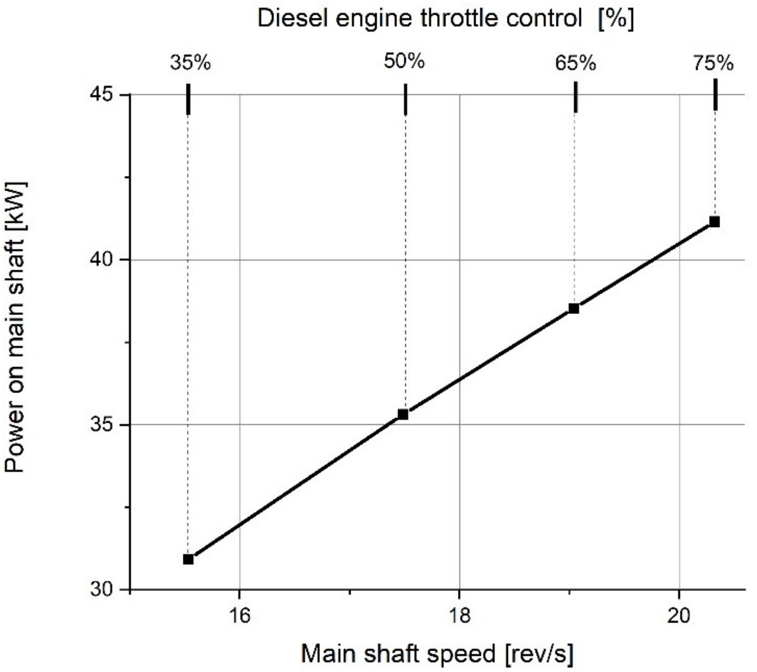
4. Experimental Research and Discussion of Results

The tests were carried out at the Laboratory of Machines and Ship Systems of the Faculty of Ocean Engineering and Ship Technology at the Gdańsk University of Technology. Presented below is a simplified schematic of the test rig (Figure 8). The propulsion system was already described (Figure 3). To carry out the measurements, the propulsion system was installed on a special, purpose-built frame. A clutch, torque meter (1) and hydraulic pump (2) were installed in the location where a propeller is placed during boat assembly. The load was applied to the propulsion system by dumping generated flow using the pump. The layout of the stand is rather complex and requires an enlarged cooling system for the combustion engine, both gears and quickly heating hydraulic oil in the load-applying system.
During the research, system parameters were tested in three operating modes:
  • diesel engine mode;
  • electric motor mode;
  • diesel engine mode with simultaneous electricity generation (diesel + generator mode).
Testing the combustion engine mode demonstrated that the entire propulsion system can transfer maximum power and the load applying system operates effectively. The results are presented in graphic form below (Figure 9). Measurements taken while operating the combustion engine were performed for different injection pump settings in the range of 35% to 75% of the maximum value.
During operation in the electric motor mode, in addition to the shaft’s power, it was possible to determine the energy efficiency of the entire system (Figure 10). By comparing the motor efficiency results recorded during the tests conducted with the motor (Figure 4), it is possible to estimate the transmission drive losses (belt transmission, 2—reduction gears, bearings and seals), which on average amount to 5%–10%.
Tests conducted in the diesel and electric mode (Figure 11), demonstrated that the generator produces enough energy to charge the batteries as needed. During regular travel, the time to fully charge the batteries should be under 6 h; although, in an ideal situation with access to electric energy source provided during mooring, the charging process should initially make use of lower currents. Under optimum conditions, the charging process should take from 6 to 12 h. In this scenario, the batteries remain durable.
In analysing the recorded measurement results, a number of interesting regularities may be observed.
The total power measurement (Figure 11), demonstrated that the combined shaft-generated and electric power is greater than the power of the engine working without the electric machine. One may suppose that this stems from the measurement limitations of the test-stand. The torque load on the main shaft was gradually increased while observing the behaviour of the combustion engine, until the moment when the engine reacted by a substantial reduction of the rotational speed of the crankshaft.
Since the test-stand described in this paper does not constitute a dedicated setup for testing combustion engine operational characteristics, there was a possibility of uncontrollably overloading the engine by torque. It is for this reason that the plan of the experiment called for placing only a partial load on the combustion engine.
The 22 kWh capacity battery block provides the vessels with good autonomous operational capabilities. At speeds below 8 km/h, it supplies enough energy for five hours of sailing (Figure 12). As the speed increases, so does the energy consumption, which in the case of lead-acid batteries, gives the effect of a drop in the real battery capacity (known as Peukert’s law). This deepens the effect of decreasing range that accompanies increasing boat speed. However, additional power from a photovoltaic installation, which the vessel is equipped with, constitutes a solution that will result in providing a substantial increase in the boat’s operational range, especially during travel at lower speeds.
Installing solar panels on ships and boats is now rather common [5,11,13,28,29]. The graph below (Figure 11) presents the effect of additional power supplied by a 0.5, 1 or 1.5 kW photovoltaic installation on the vessel’s range—the distance that the ship will sail during the day in good sunny and windless weather. As it turns out, during travel at speeds below 6 km/h, there is sufficient energy for about 12 h (an entire sunny day).

5. Conclusions

  • It worth observing certain significant limitations of the propulsion system stemming from using a simple, inexpensive and widely used fixed pitch propeller. In a typical case, when the propeller is selected for a precise combustion engine, during travel using electric propulsion, it might turn out that the lesser-powered electric motor is not capable of effective work with the propeller, as it is not able to generate sufficient torque. Usually, in such a case, a reduction gear is used, which allows for increasing the torque on the propeller shaft, while accepting that the lesser-powered electric motor drives the propeller shaft at a lower speed. However, a problem appears during work in the generator mode. The reduction gear becomes a multiplying gear and the electric machine works at a significantly faster pace than in the motor mode. Since the voltage generated by the electric machine with permanent magnets depends on the rotational speed of the shaft, it turns out that the generated voltage is much greater than the supplied voltage. This may cause a system failure with dangerous consequences. Therefore, in the case of a hybrid propulsion system, an ideal solution would be to employ continuously variable transmission (CVT)—similar to its use in vehicles. Another very good but complex solution would be to use an adjustable pitch propeller, which can change the attack angle of the blades to fit sailing conditions [30,31,32,33].
  • Retrofitting the vessel will result in increasing its total mass by approximately 5%–7%. Consequently, there will be increases in resistance and energy demand. Based on our own model studies of comparably sized objects, one may speculate that the levels of resistance will increase by approximately 5%.
  • No successful tests were completed in the mode of two engines operating simultaneously. There was a problem with the electric motor being powered by a frequency converter with rotational speed control. Work on modifying the controller’s software is problematic as the manufacturer is not very co-operative when it comes to sharing technical specifications of the device.
  • Losses in the mechanical power transfer system are, on average, 5%–10%, which is acceptable. If the absolute priority were energy efficiency, then a tooth gear transmission should be used instead of a belt one. However, belt transmission has a unique characteristic that is especially useful at the prototype test stage. By changing one of the wheels, the gearing ratio may be modified to fit a specific propeller.
  • The range and autonomous character of the vessel may be substantially increased by adding photovoltaic panels. It is anticipated that six panels having 1.5 kWp combined peak power will be installed on the retrofitted watercraft.
  • It is worth adding that installing a parallel hybrid propulsion system on a vessel generally increases the level of safety. This is due to the fact that the unit has two drive units mounted, which can work independently. So if one of the systems brakes, the second can operate.

Author Contributions

W.L. (Wojciech Litwin) developed the project concept. W.L. (Wojciech Leśniewski) and W.L. (Wojciech Litwin) designed and constructed the hybrid propulsion system. K.M. designed and built the electrical and data acquisition systems. W.L. (Wojciech Leśniewski), D.P. and K.M. designed and performed the experiments. W.L. (Wojciech Leśniewski) analysed and processed the acquired data. W.L. (Wojciech Litwin) authored the manuscript. All the authors discussed the results and contributed to the final manuscript. All authors have read and agreed to the published version of the manuscript.

Funding

This work was a part of research grant no. POIR.01.01.01-00-1091/18 entitled “Development of a prototype sea-going catamaran with hybrid propulsion and energy recovery during sailing” financed by the Polish National Centre for Research and Development. The APC was financed by Faculty of Ocean Engineering and Ship Technology, Gdansk University of Technology, Poland.

Conflicts of Interest

The authors declare no conflict of interest.

References

  1. Misyris, G.; Marinopoulos, A.; Doukas, D.; Tengnér, T.; Labridis, D. On battery state estimation algorithms for electric ship applications. Electr. Power Syst. Res. 2017, 151, 115–124. [Google Scholar] [CrossRef]
  2. Geertsma, R.; Negenborn, R.; Visser, K.; Hopman, J. Parallel control for hybrid propulsion of multifunction ships. IFAC PapersOnLine 2017, 50, 2296–2303. [Google Scholar] [CrossRef]
  3. García, P.; Fernández, L.M.; Torreglosa, J.P.; Jurado, F.; Fernandez-Ramirez, L.M. Operation mode control of a hybrid power system based on fuel cell/battery/ultracapacitor for an electric tramway. Comput. Electr. Eng. 2013, 39, 1993–2004. [Google Scholar] [CrossRef]
  4. Gao, D.; Jin, Z.; Zhang, J.; Li, J.; Ouyang, M. Comparative study of two different powertrains for a fuel cell hybrid bus. J. Power Sources 2016, 319, 9–18. [Google Scholar] [CrossRef]
  5. Yang, R.; Yuan, Y.; Ying, R.; Shen, B.; Long, T. A novel energy management strategy for a ship’s hybrid solar energy generation system using a particle swarm optimization algorithm. Energies 2020, 13, 1380. [Google Scholar] [CrossRef] [Green Version]
  6. Hayajneh, H.S.; Zhang, X. Logistics design for mobile battery energy storage systems. Energies 2020, 13, 1157. [Google Scholar] [CrossRef] [Green Version]
  7. Tillig, F.; Ringsberg, J.W.; Mao, W.; Ramne, B. Analysis of uncertainties in the prediction of ships’ fuel consumption—From early design to operation conditions design to operation conditions. Ships Offshore Struct. 2018. [Google Scholar] [CrossRef]
  8. Kalargaris, I.; Tian, G.; Gu, S. Combustion, performance and emission analysis of a DI diesel engine using plastic pyrolysis oil. Fuel Process. Technol. 2017, 157, 108–115. [Google Scholar] [CrossRef] [Green Version]
  9. Shih, N.-C.; Weng, B.-J.; Lee, J.-Y.; Hsiao, Y.-C. Development of a 20 kW generic hybrid fuel cell power system for small ships and underwater vehicles. Int. J. Hydrogen Energy 2014, 39, 13894–13901. [Google Scholar] [CrossRef]
  10. Gagatsi, E.; Estrup, T.; Halatsis, A. Exploring the potentials of electrical waterborne transport in Europe: The E-ferry concept. Transp. Res. Procedia 2016, 14, 1571–1580. [Google Scholar] [CrossRef] [Green Version]
  11. Nasirudin, A.; Chao, R.-M.; Utama, I.K.A.P. Solar powered boat design optimization. Procedia Eng. 2017, 194, 260–267. [Google Scholar] [CrossRef]
  12. Liu, H.; Zhang, Q.; Qi, X.; Han, Y.; Lu, F. Estimation of PV output power in moving and rocking hybrid energy marine ships. Appl. Energy 2017, 204, 362–372. [Google Scholar] [CrossRef]
  13. Tang, R. Large-scale photovoltaic system on green ship and its MPPT controlling. Sol. Energy 2017, 157, 614–628. [Google Scholar] [CrossRef]
  14. Dymarski, C. A concept design of diesel—Hydraulic propulsion system for passenger ship intended for inland shallow water navigation. Pol. Marit. Res. 2019, 26, 30–38. [Google Scholar] [CrossRef] [Green Version]
  15. Piątek, D. New concept of hybrid propulsion with hydrostatic gear for inland water transport. Pol. Marit. Res. 2019, 26, 134–141. [Google Scholar] [CrossRef] [Green Version]
  16. Alfonsín, V.; Suarez, A.; Cancela, A.; Sanchez, A.; Maceiras, R. Modelization of hybrid systems with hydrogen and renewable energy oriented to electric propulsion in sailboats. Int. J. Hydrogen Energy 2014, 39, 11763–11773. [Google Scholar] [CrossRef]
  17. Carter, C. Zero oil means zero enviromental impact. Nav. Archit. 2012, 5, 32–36. [Google Scholar]
  18. Kazienko, D.; Chybowski, L. Instantaneous rotational speed algorithm for locating malfunctions in marine diesel engines. Energies 2020, 13, 1396. [Google Scholar] [CrossRef] [Green Version]
  19. Verge, T. An Inside Look at the World’s Largest Solar-Powered Boat. 2016, pp. 1–13. Available online: http://www.theverge.com/2013/6/22/4454980/ms-turanor-planetsolar-s (accessed on 18 May 2020).
  20. Geertsma, R.; Negenborn, R.; Visser, K.; Hopman, J. Design and control of hybrid power and propulsion systems for smart ships: A review of developments. Appl. Energy 2017, 194, 30–54. [Google Scholar] [CrossRef]
  21. Di Nicolantonio, M.; Lagatta, J.; Vallicelli, A. 80 Feet Sustainable Motoryacht: Technological Solutions Concept of the Living Spaces on Board. Procedia Manuf. 2015, 3, 2698–2705. [Google Scholar] [CrossRef] [Green Version]
  22. Karczewski, A.; Kozak, J. Variant designing in the preliminary small ship design process. Pol. Marit. Res. 2017, 24, 77–82. [Google Scholar] [CrossRef]
  23. Gełesz, P.; Karczewski, A.; Kozak, J.; Litwin, W.; Piątek, Ł. Design methodology for small passenger ships on the example of the ferryboat Motława 2 driven by hybrid propulsion system. Pol. Marit. Res. 2017, 24, 67–73. [Google Scholar] [CrossRef] [Green Version]
  24. Łebkowski, A. Analysis of the use of electric drive systems for crew transfer vessels servicing offshore wind farms. Energies 2020, 13, 1466. [Google Scholar]
  25. Kunicka, M.; Litwin, W. Energy efficient small inlad passenger shuttle ferry with hybrcid propulsion—Concept design, calculations and model tests. Polish Marit. Res. 2019, 26, 85–92. [Google Scholar] [CrossRef] [Green Version]
  26. Kowalski, J.; Leśniewski, W.; Litwin, W. Multi-source-supplied parallel hybrid propulsion of the inland passenger ship STA.H. Research work on energy efficiency of a hybrid propulsion system operating in the electric motor drive mode. Pol. Marit. Res. 2013, 20, 20–27. [Google Scholar] [CrossRef] [Green Version]
  27. Kunicka, M.; Litwin, W. Energy demand of short-range inland ferry with series hybrid propulsion depending on the navigation strategy. Energies 2019, 12, 3499. [Google Scholar] [CrossRef] [Green Version]
  28. Wang, H.; Oguz, E.; Jeong, B.; Zhou, P. Life cycle and economic assessment of a solar panel array applied to a short route ferry. J. Clean. Prod. 2019, 219, 471–484. [Google Scholar] [CrossRef] [Green Version]
  29. Lan, H.; Wen, S.; Hong, Y.-Y.; Yu, D.C.; Zhang, L. Optimal sizing of hybrid PV/diesel/battery in ship power system. Appl. Energy 2015, 158, 26–34. [Google Scholar] [CrossRef] [Green Version]
  30. Bertini, L.; Carmignani, L.; Frendo, F. Analytical model for the power losses in rubber V-belt continuously variable transmission (CVT). Mech. Mach. Theory 2014, 78, 289–306. [Google Scholar] [CrossRef]
  31. Tomaselli, M.; Lino, P.; Carbone, G. Modelling and efficiency formulation of a planetary traction drive CVT. IFAC PapersOnLine 2019, 52, 411–416. [Google Scholar] [CrossRef]
  32. Liu, J.; Sun, D.; Ye, M.; Liu, X.; Li, B. Study on the transmission efficiency of electro-mechanical continuously variable transmission with adjustable clamping force. Mech. Mach. Theory 2018, 126, 468–478. [Google Scholar] [CrossRef]
  33. Chung, C.-T.; Wu, C.-H.; Hung, Y.-H. Evaluation of driving performance and energy efficiency for a novel full hybrid system with dual-motor electric drive and integrated input- and output-split e-CVT. Energy 2020, 191, 116508. [Google Scholar] [CrossRef]
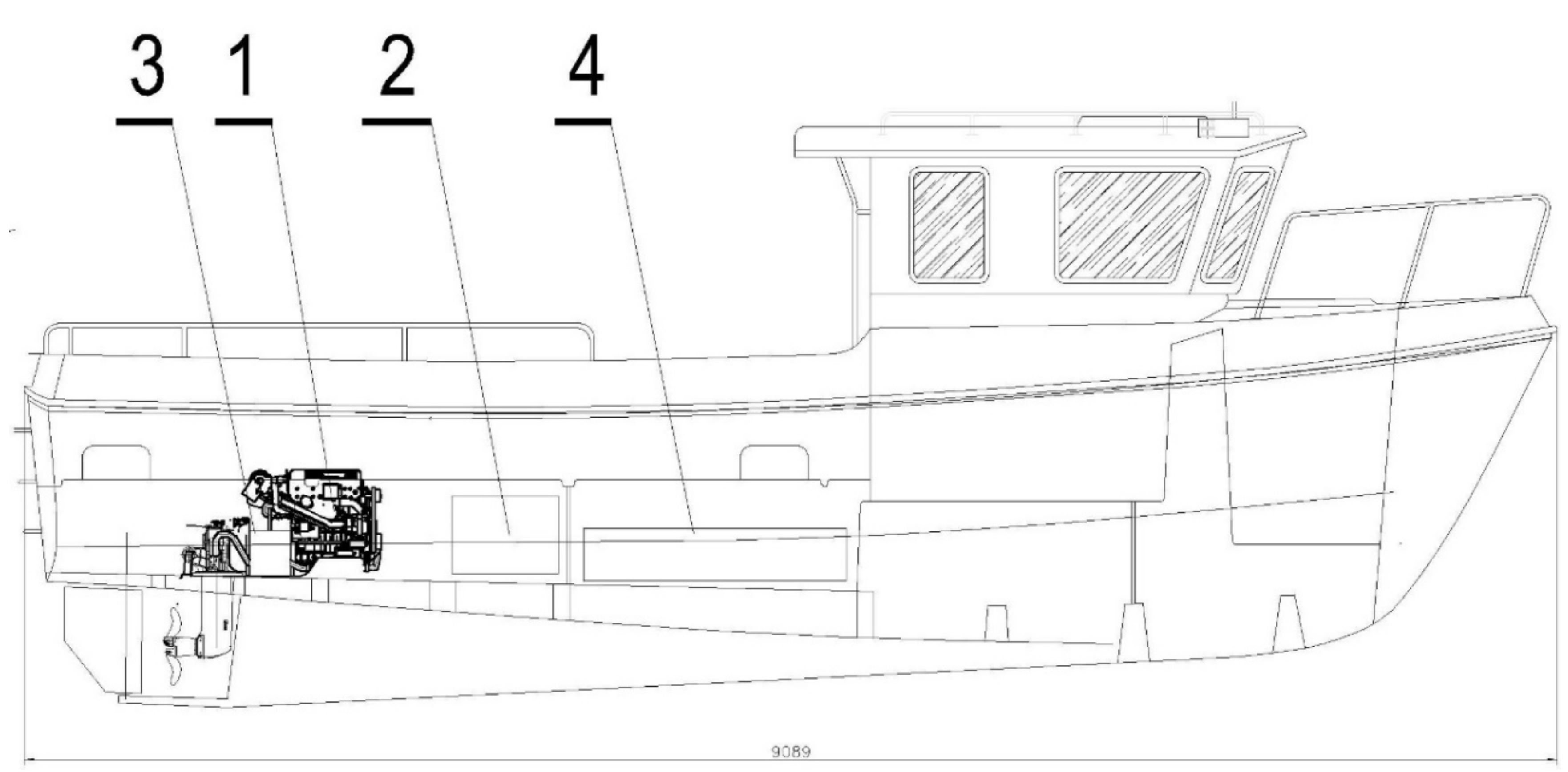
Figure 1. Conrad-900 vessel—general view; 1—combustion engine with reduction gear, 2—fuel tank.
Energies 13 02586 g001
Figure 2. Towing power diagram—for calm water conditions.
Energies 13 02586 g002
Figure 3. Designed and built parallel hybrid drive system; (a) schematic, (b) assembly drawing; 1—combustion engine, 2—electric motor, 3—clutch and belt drive module, 4—gear with reverse, 5—bottom reduction gear, 6—propeller.
Energies 13 02586 g003
Figure 4. Power and efficiency of a 10 kW electric motor as a function of motor shaft speed.
Energies 13 02586 g004
Figure 5. Selected belts efficiency diagram, data acquired during laboratory tests.
Energies 13 02586 g005
Figure 6. Estimation of electric power demand during sailing in favourable conditions—calm water.
Energies 13 02586 g006
Figure 7. Conrad-900 vessel after retrofitting; 1—engine, 2—fuel tank, 3—electric motor/generator module, 4—battery.
Energies 13 02586 g007
Figure 8. Test rig schematic; 1—torque meter on the main shaft, hydraulic pump and hydraulic system for applying load, 2—hydraulic pump—load system.
Energies 13 02586 g008
Figure 9. Power on the main shaft in diesel mode.
Energies 13 02586 g009
Figure 10. Power and efficiency of the system in electric motor mode.
Energies 13 02586 g010
Figure 11. Power on the main shaft and electric power generated in diesel plus generator mode.
Energies 13 02586 g011
Figure 12. Prognosis of the vessel’s operating range during travel at various speeds in favourable atmospheric conditions; alternatives with and without photovoltaic installation (PV) and various power levels generated by the installation.
Energies 13 02586 g012
Table 1. Conrad-900 main data.
Length overall9.10 m
Waterline length8.2 m
Beam3 m
Draft0.95 m
Displacement3.5 tons
Engine60 kW
Table 2. Propulsion system data.
Propulsion System
1Diesel-fuel powered combustion engine four cylinders, allowed for use on recreational and commercial vessels44 kW
23-phase electric motor, 48 V with permanent magnets, encoder equipped, powered by a dedicated frequency converter10 kW
3000 rev/min
Transmission Drive
3Toothed gear with reverse2.19:1
Bevel reduction gear
Power Supply
Lead-acid batteries, 8 × 12 V 230 Ah22 kWh
Fuel tank200 Litres

