Centralized-Decentralized Control for Regenerative Braking Energy Utilization and Power Quality Improvement in Modified AC-Fed Railways


Abstract
:
1. Introduction
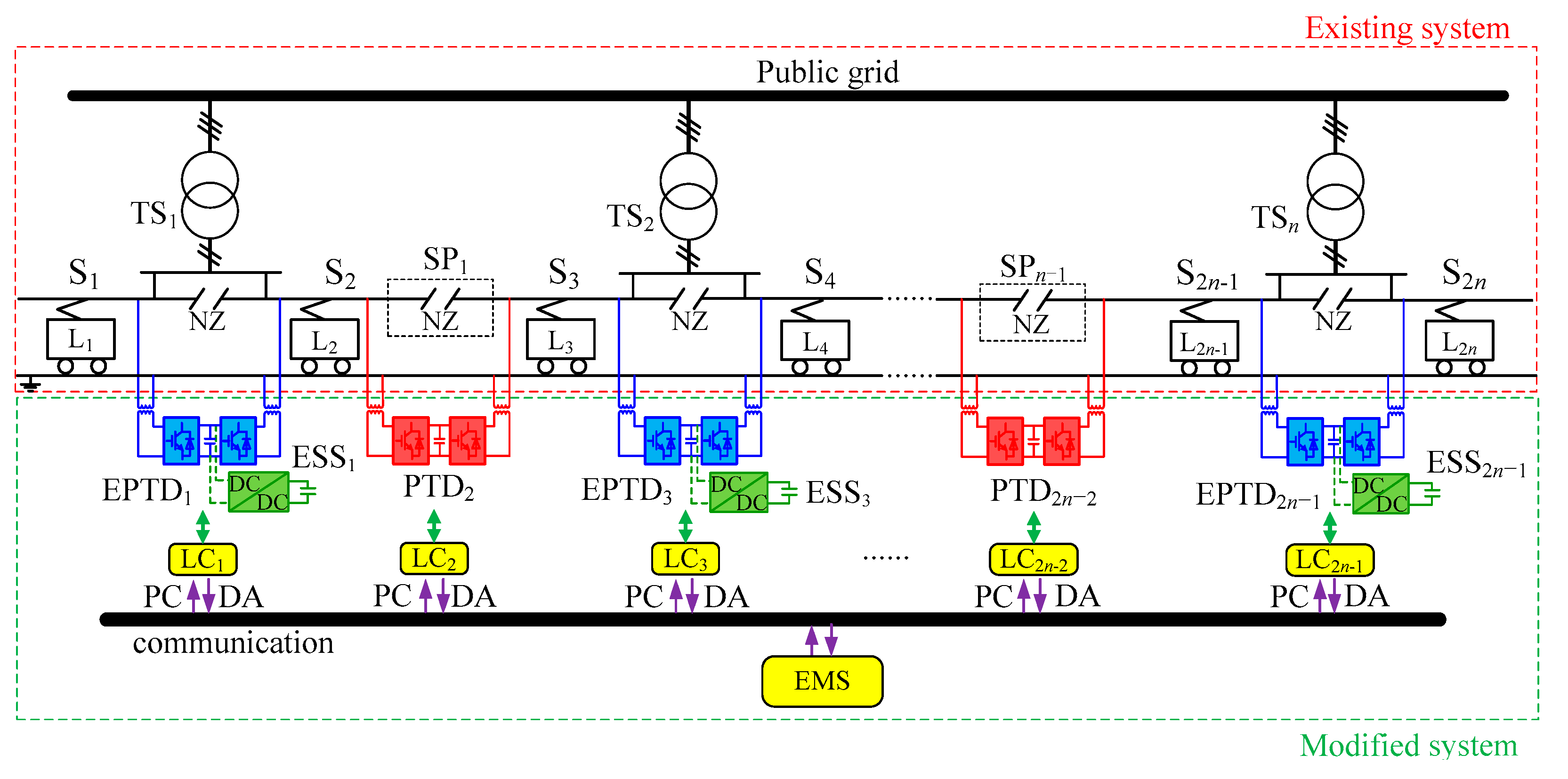
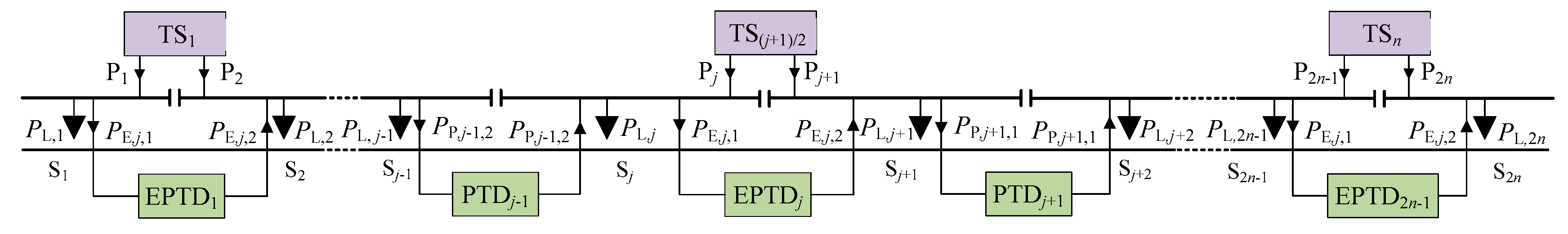
2. Description of the Modified Railway System and Its Control Strategy
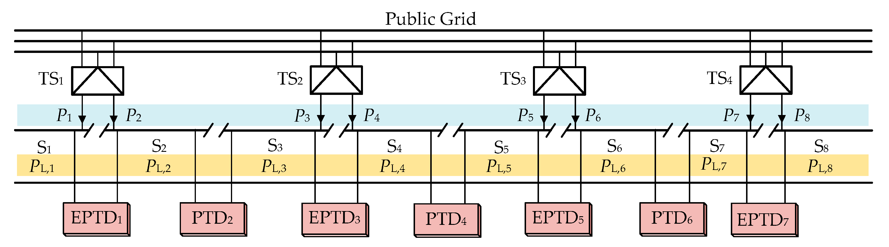
2.1. Description of the Modified Railway System
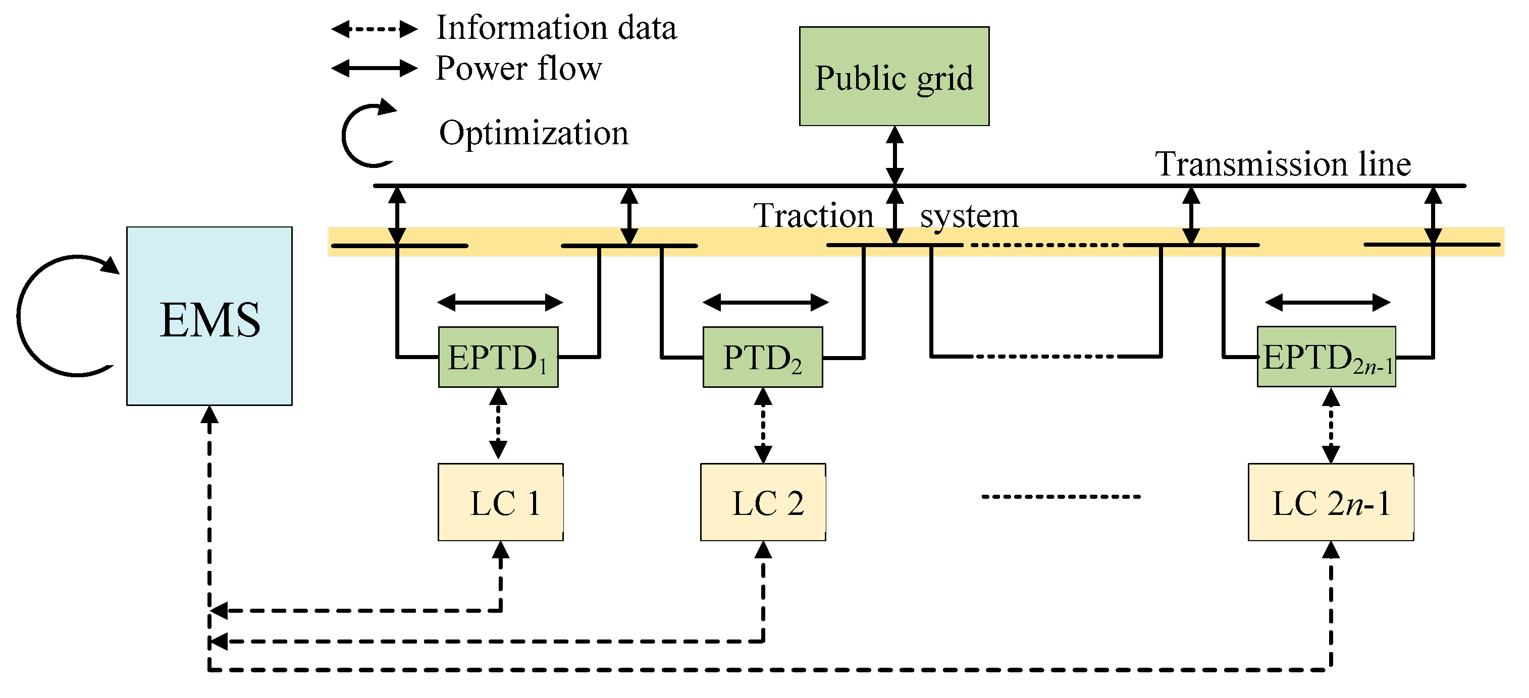
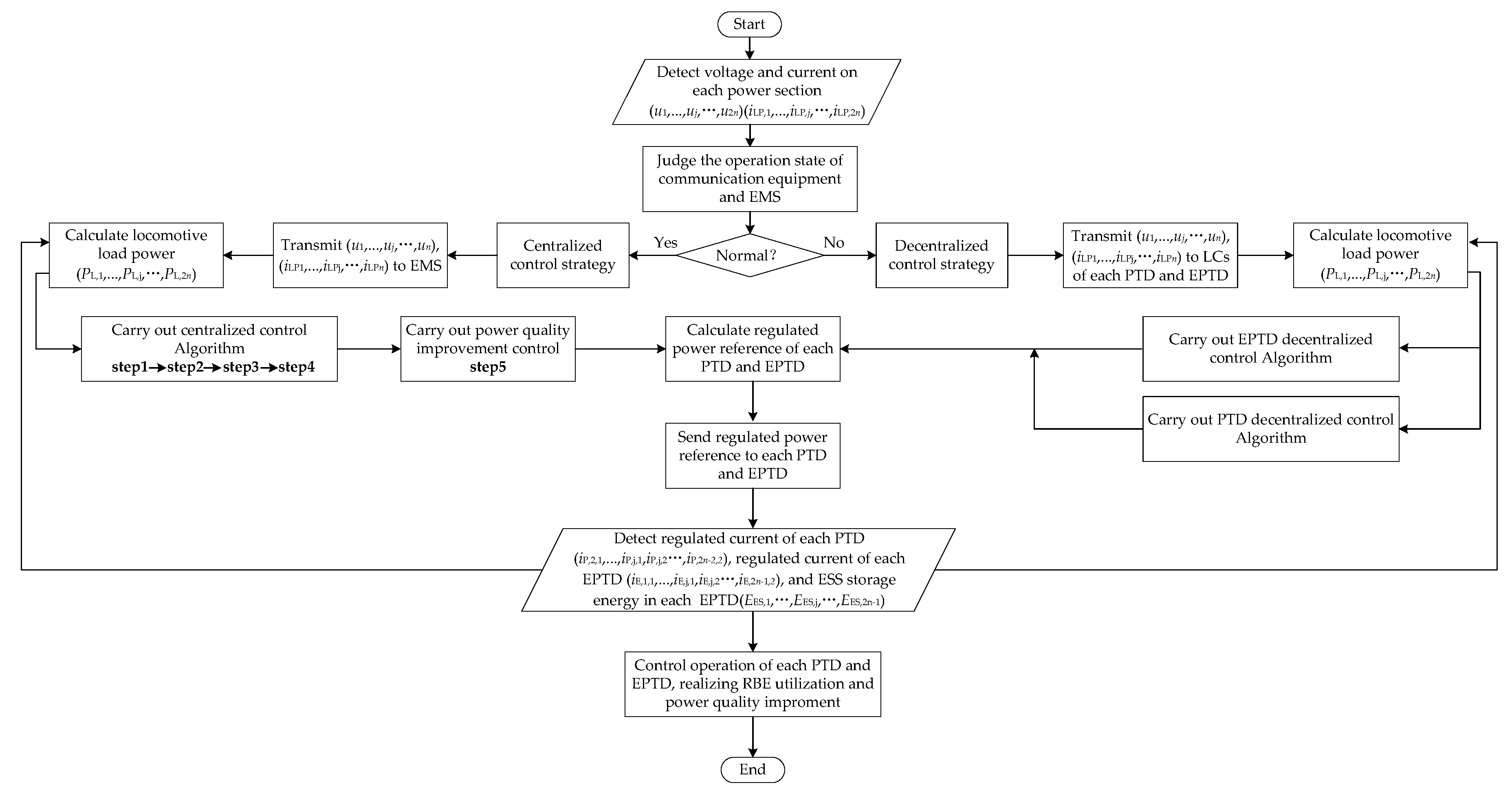
2.2. Description of the Control Strategy
3. Centralized-Decentralized Control Strategy
- (1)
- Neglect the loss of the RBE in the flow process.
- (2)
- The capacity of the ESSs was considered to be unlimited.
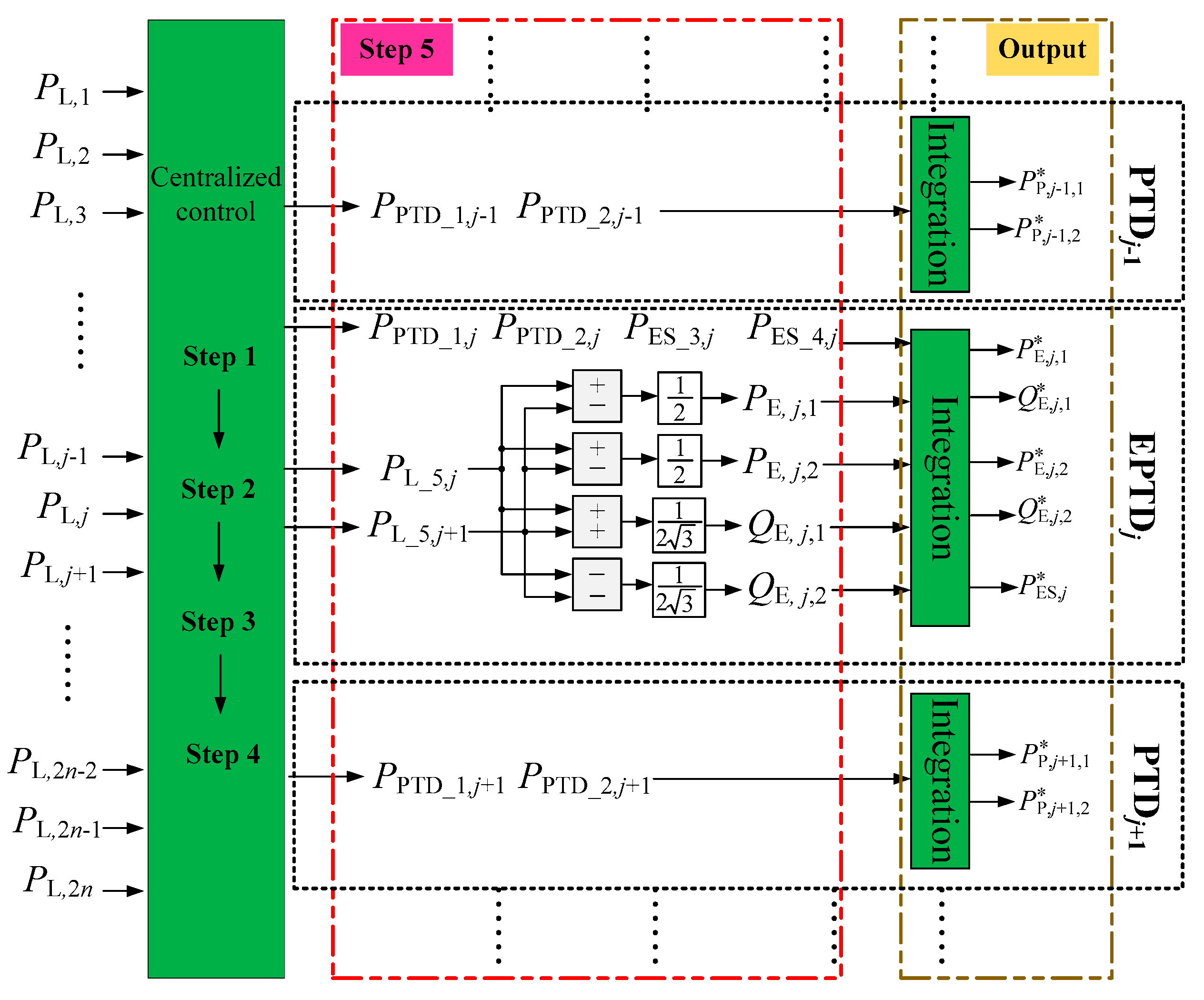
3.1. Centralized Control Strategy
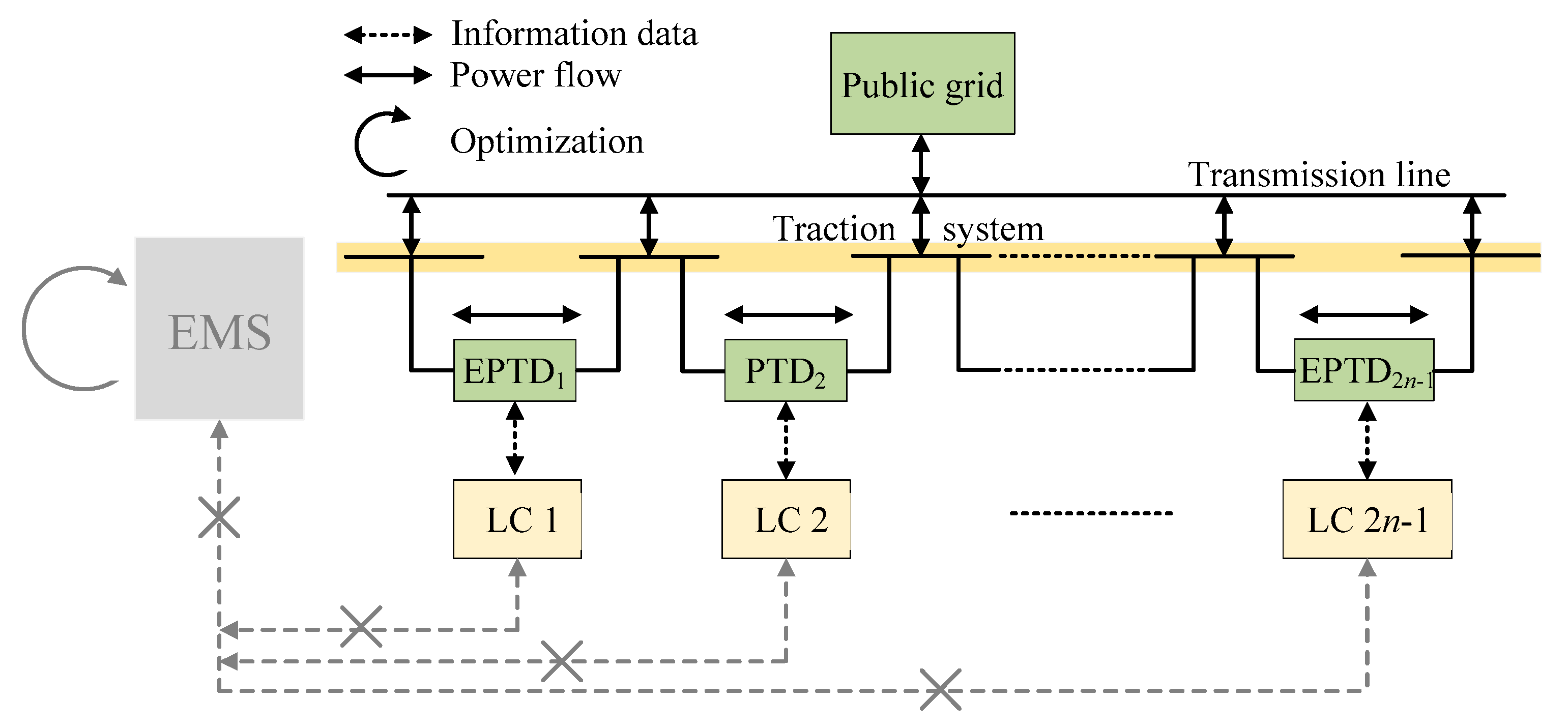
3.2. Decentralized Control Strategy
- (1)
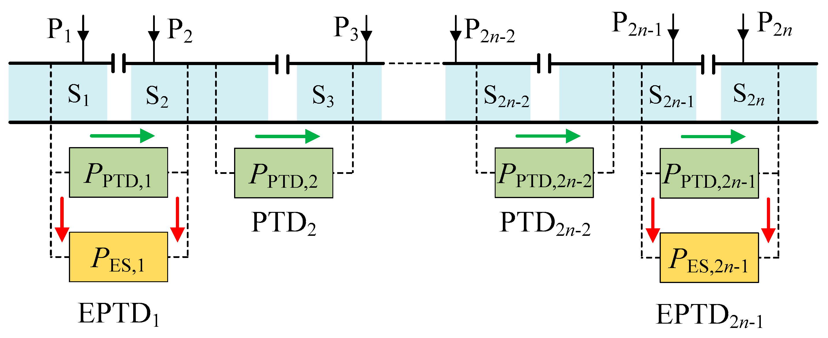
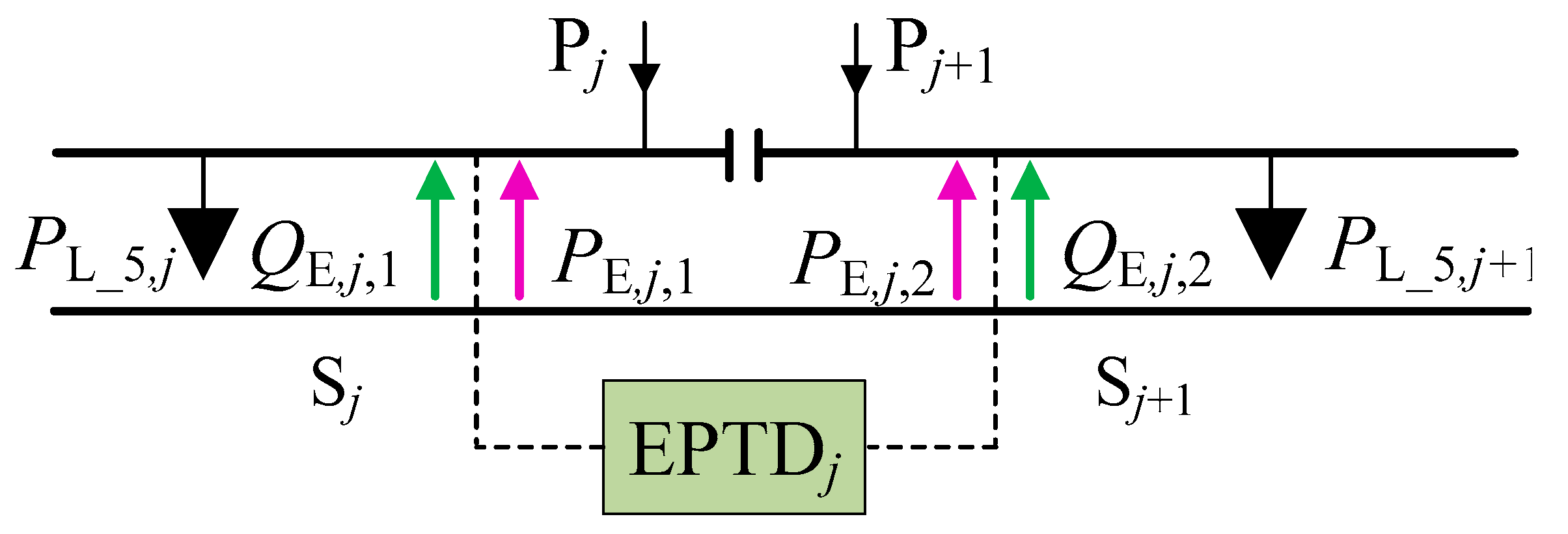
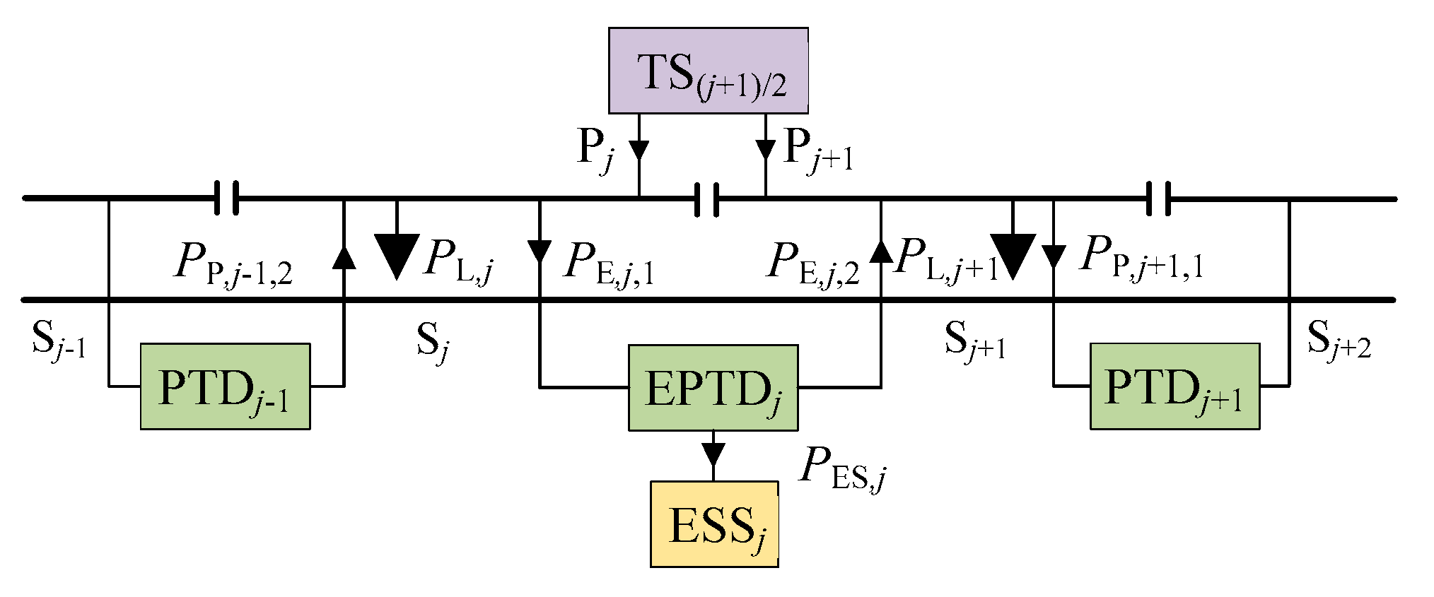
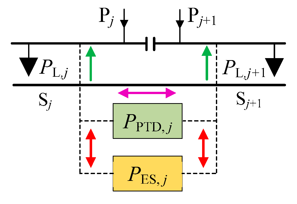
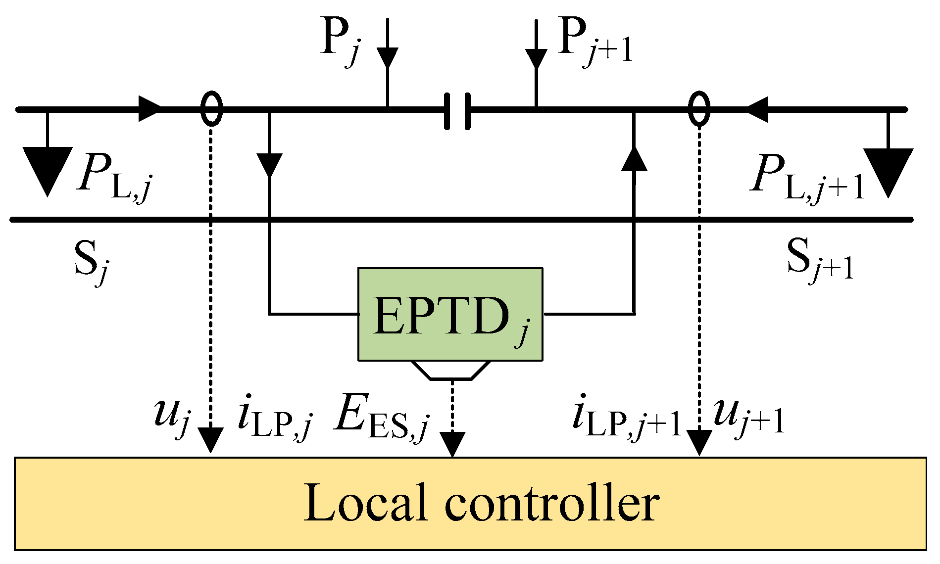
- EPTD automatically performs the function of improving the power quality to realize the automatic utilization of RBE between two power supply sections in the same TS, and according to the locomotive load power of two power supply sections, calculates the charge and discharge power of EES.
- (2)
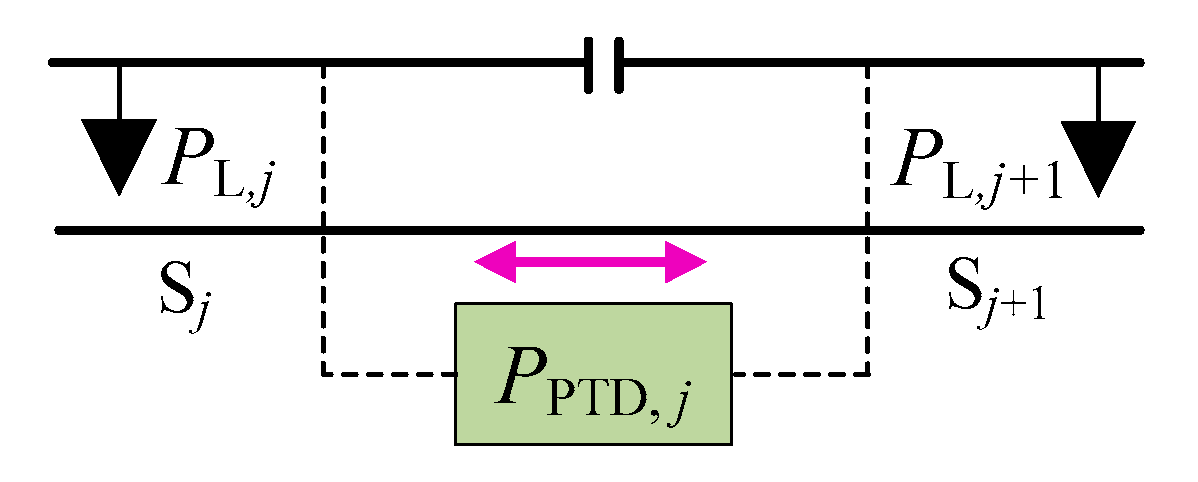
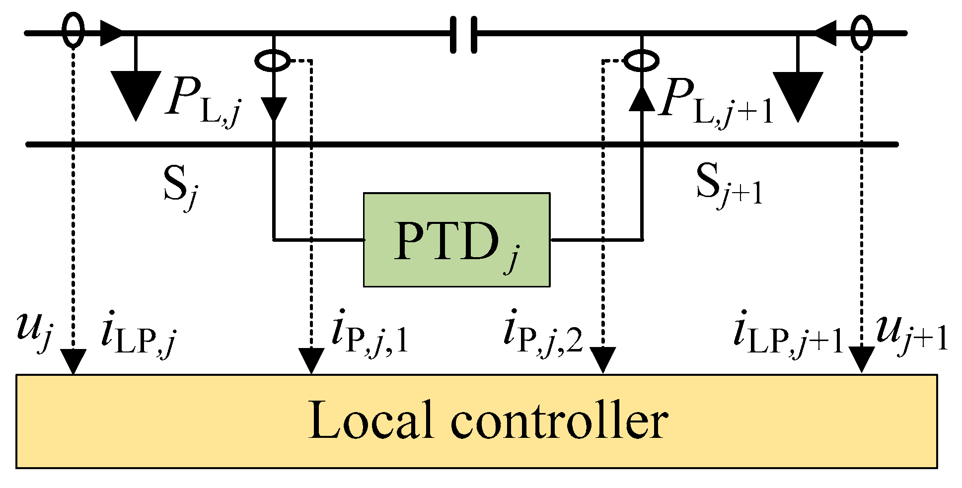
- PTD automatically performs the function of regulating the RBE to realize the utilization of RBE between two power supply sections in the adjacent TSs, and according to the locomotive load power of two power supply sections, calculates the regulated power of PTD.
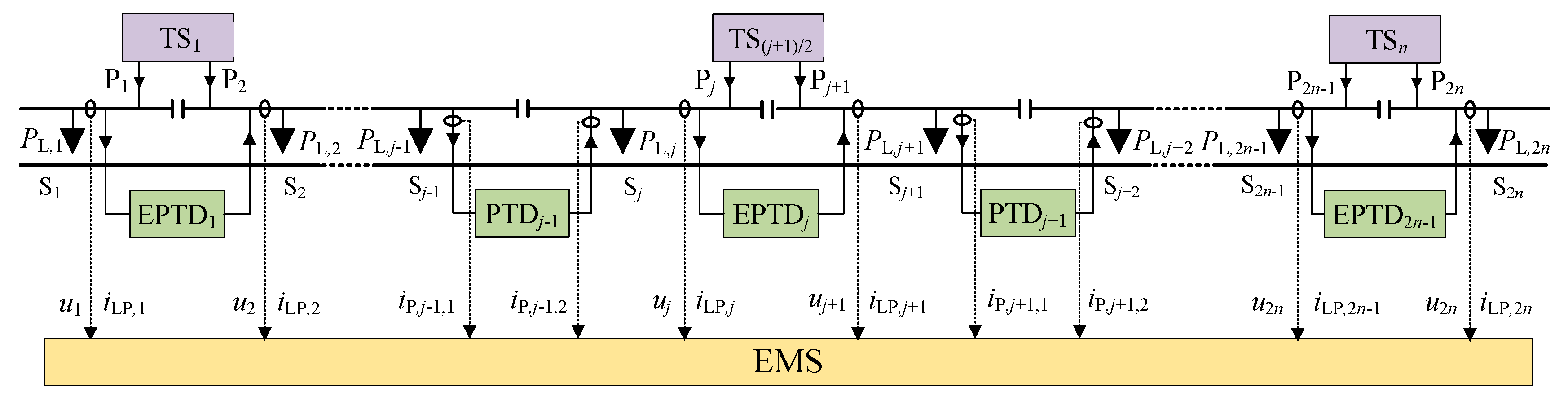
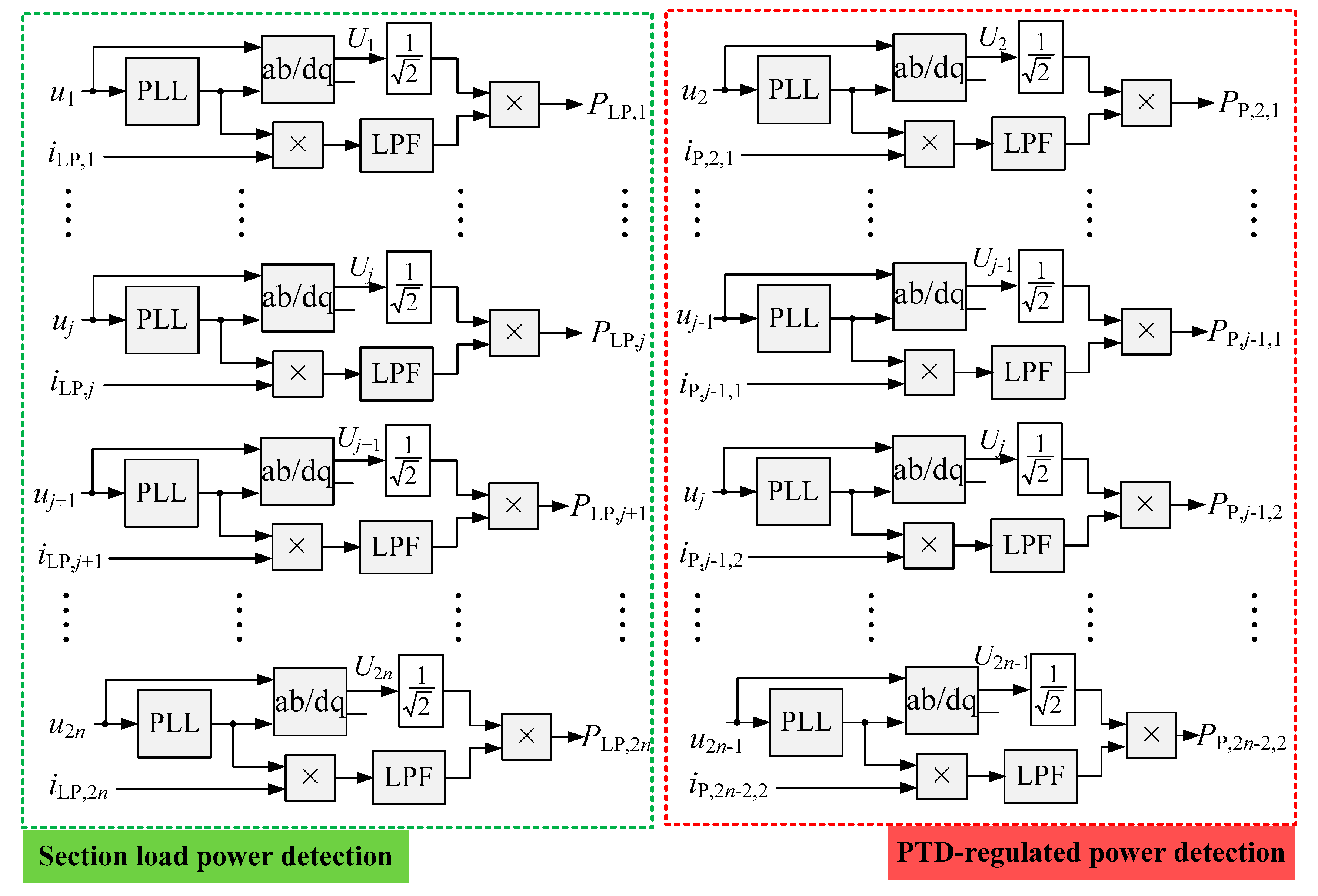
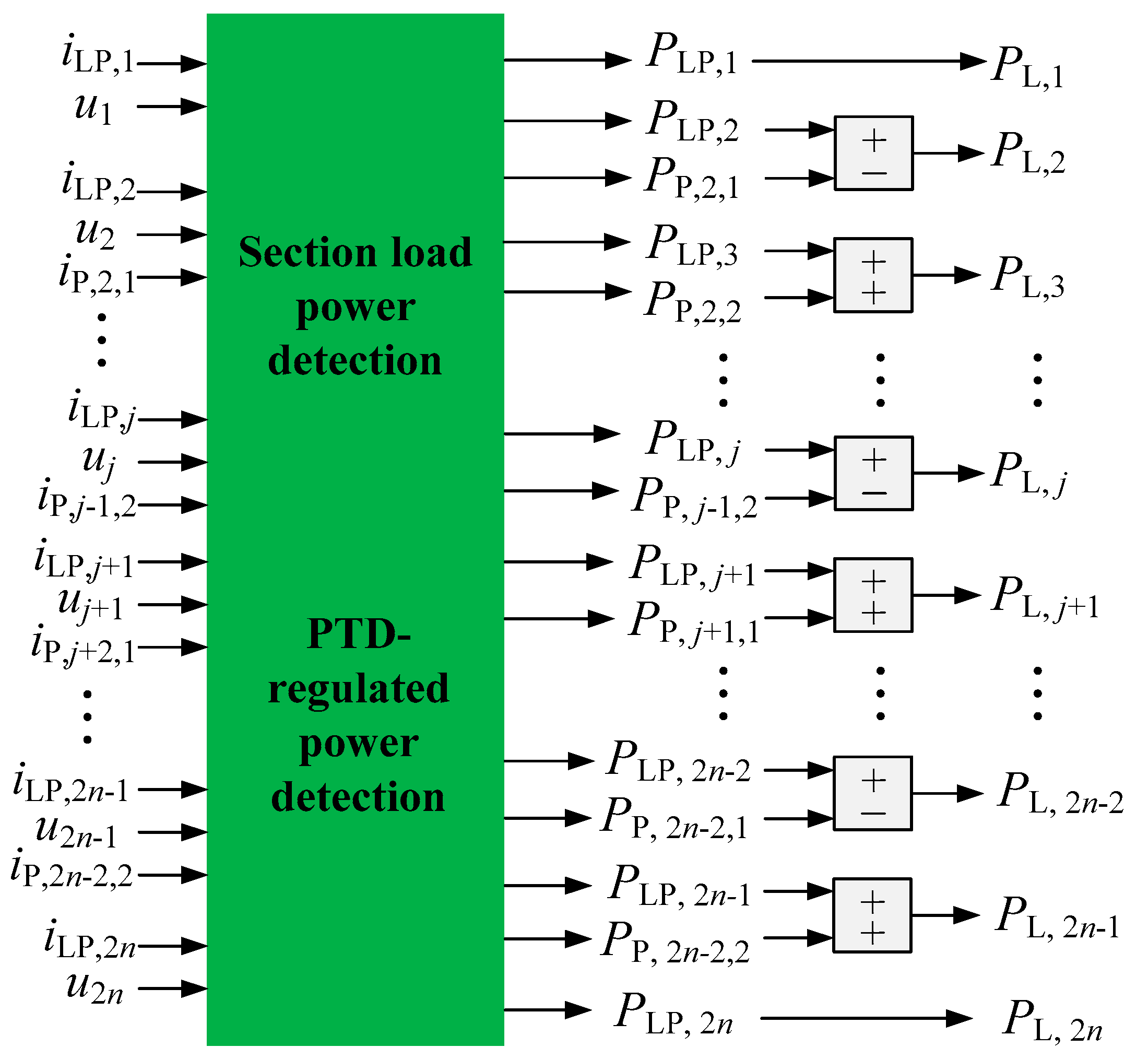
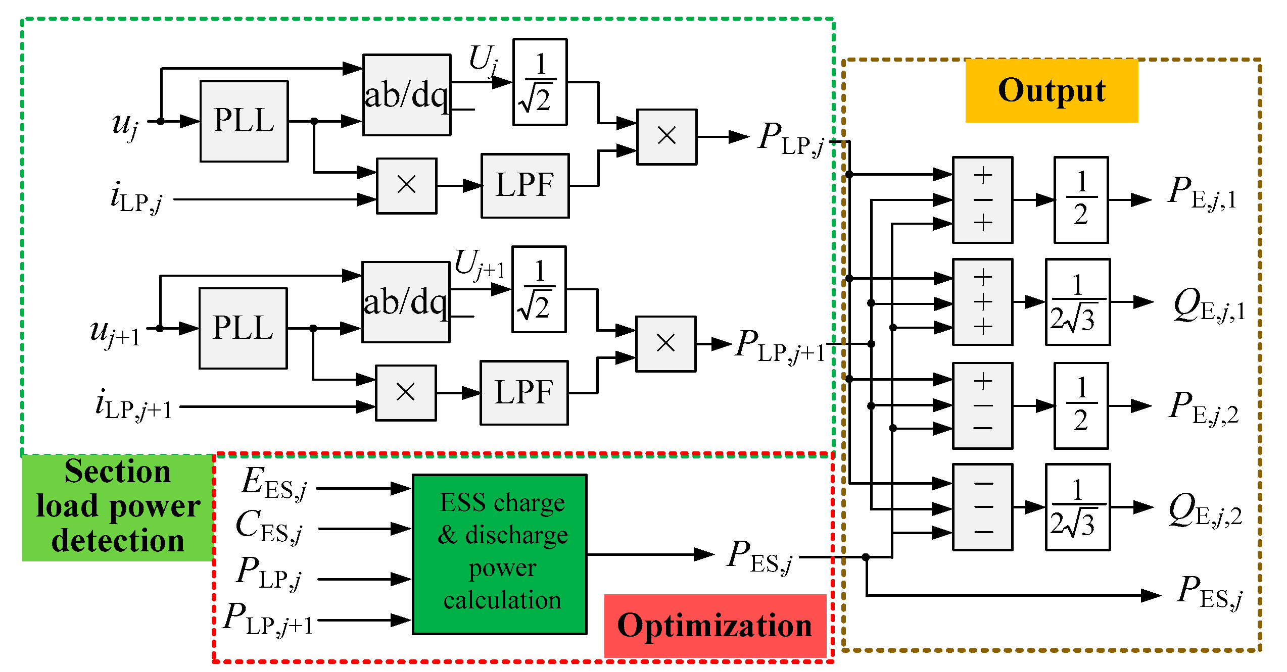
4. Load Power Detection and Regulated Power Reference Calculation
4.1. Detection Principle in Centralized Control
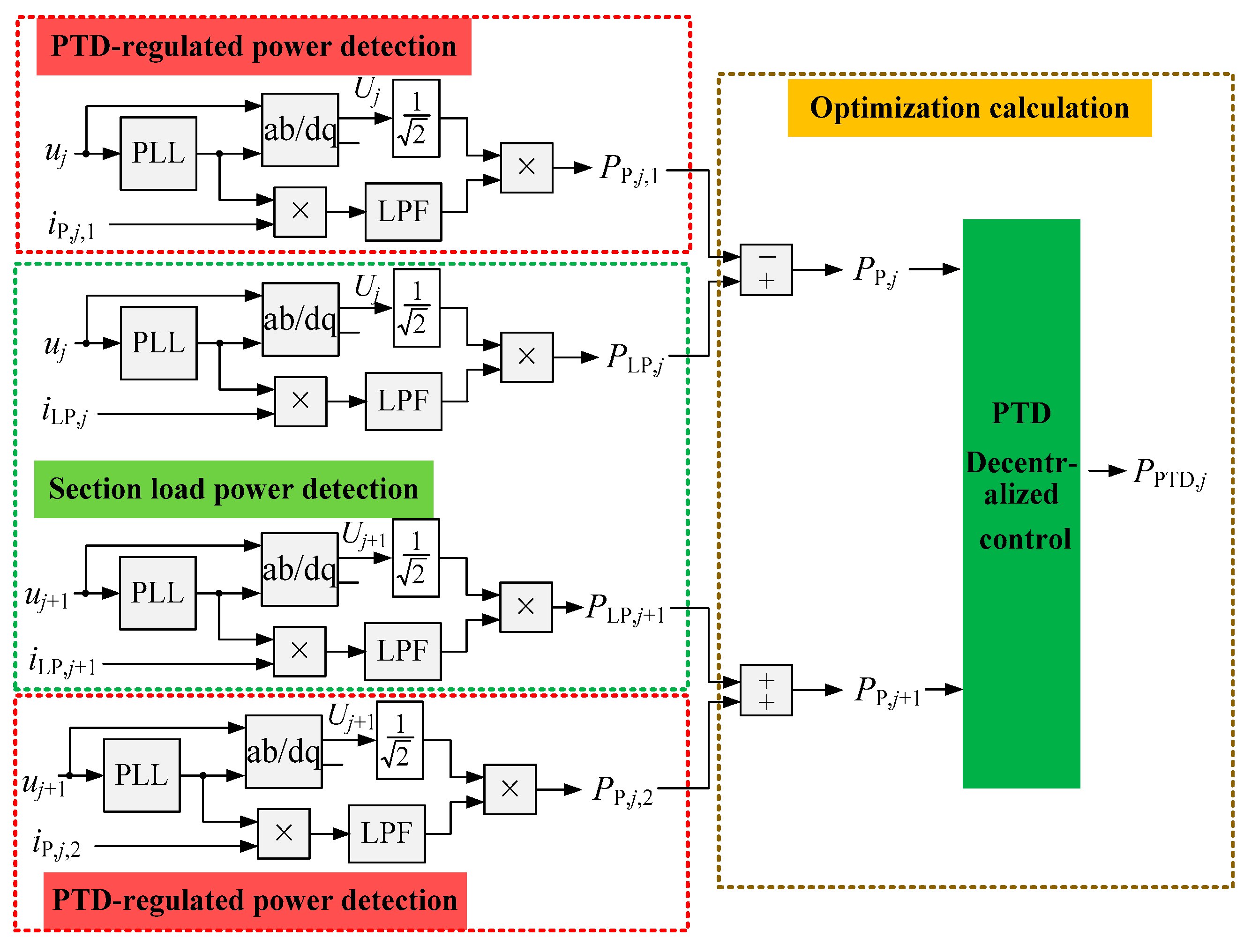
4.2. Detection Principle in Decentralized Control
5. Results Verification and Analysis
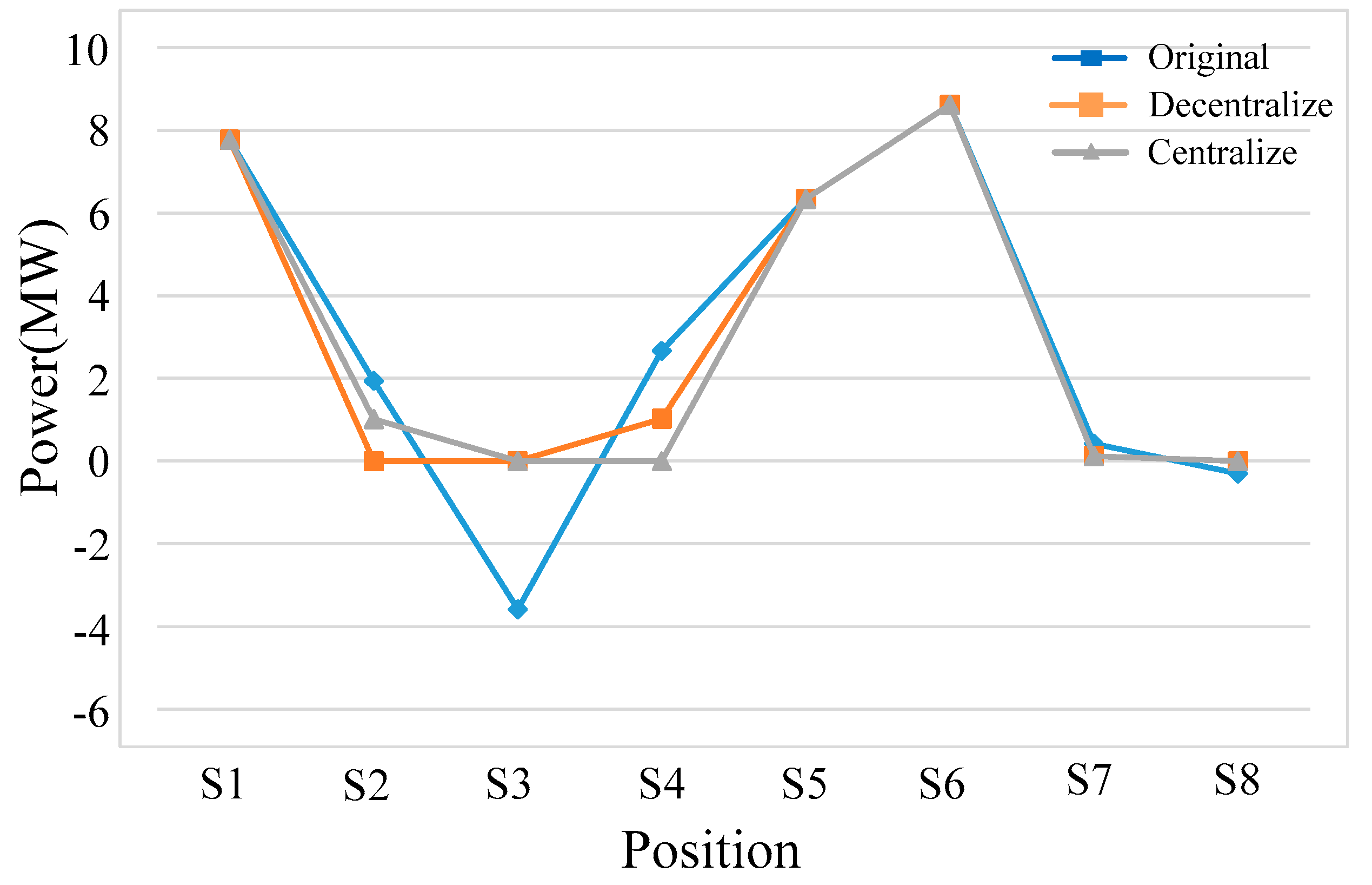
5.1. Feasibility Evaluation of the Centralized-Decentralized Control Strategy
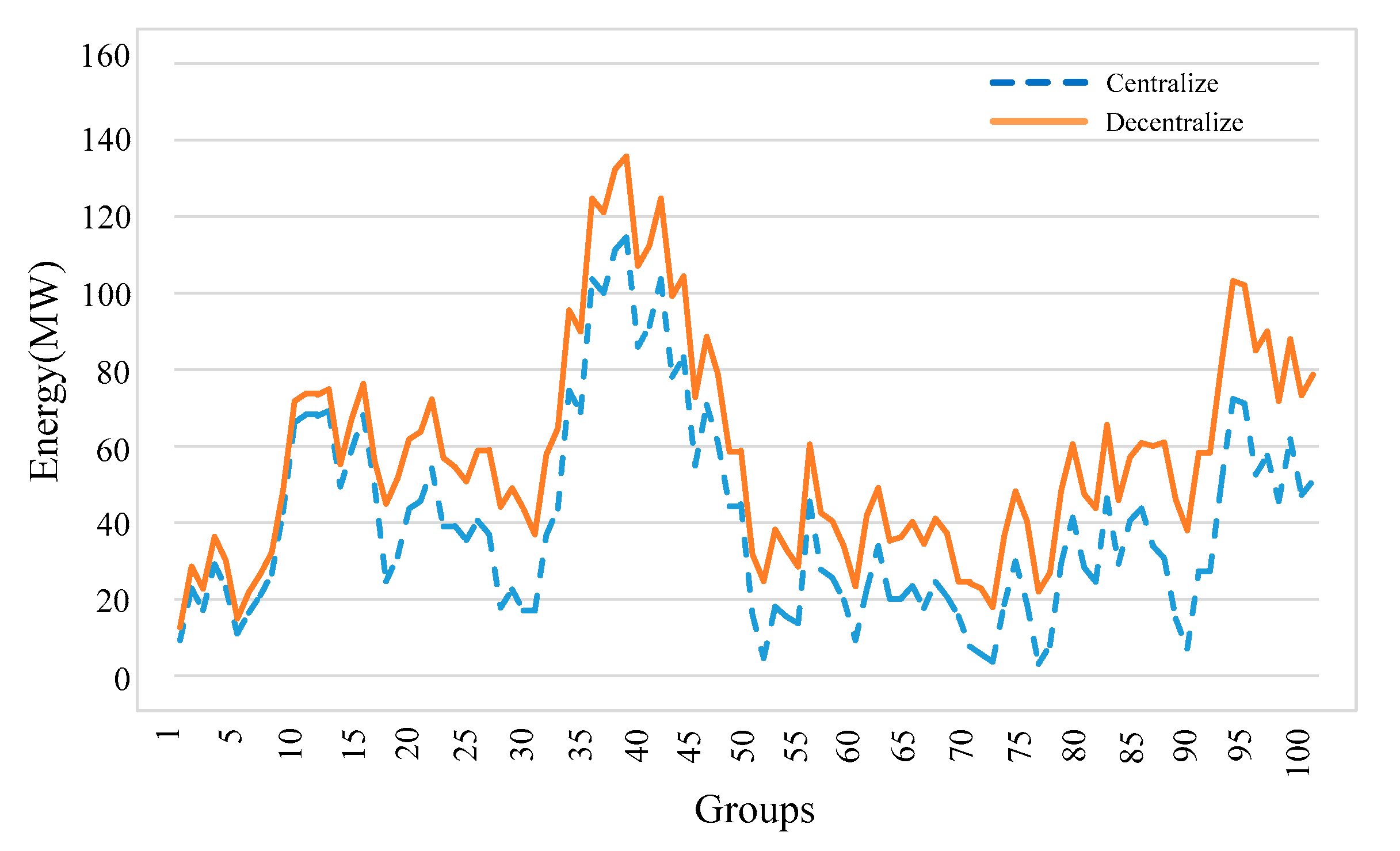
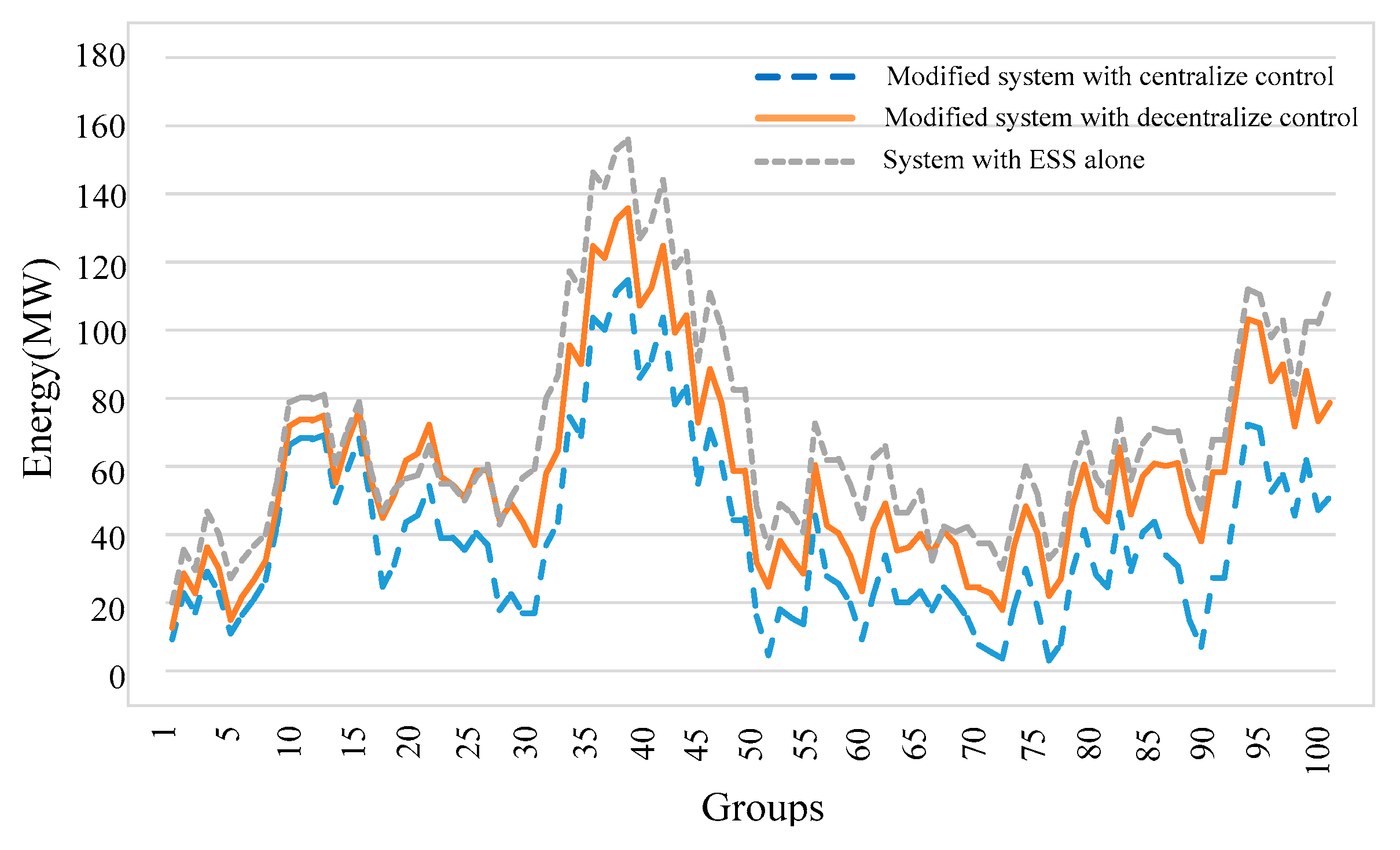
5.2. Energy Storage Performance Comparison of the Centralized and Decentralized Control Strategy
6. Conclusions
Author Contributions
Funding
Conflicts of Interest
References
- Serrano-Jiménez, D.; Abrahamsson, L.; Castaño, S.P.; Sanz-Feito, J. Electrical railway power supply systems: Current situation and future trends. Int. J. Electr. Power Energy Syst. 2017, 92, 181–192. [Google Scholar] [CrossRef]
- Hayashiya, H.; Yokokawa, S.; Iino, Y.; Kikuchi, S.; Suzuki, T.; Uematsu, S.; Sato, N.; Usui, T. Regenerative energy utilization in a.c. traction power supply system. In Proceedings of the 2016 IEEE International Power Electronics and Motion Control Conference (PEMC), Varna, Bulgaria, 25–28 September 2016; pp. 1125–1130. [Google Scholar]
- Ronanki, D.; Singh, S.A.; Williamson, S. Comprehensive Topological Overview of Rolling Stock Architectures and Recent Trends in Electric Railway Traction Systems. IEEE Trans. Transp. Electrif. 2017, 3, 724–738. [Google Scholar] [CrossRef]
- The International Energy Agency (IEA) and the International Union of Railways (UIC). Railway Handbook: Energy Consumption and CO2 Emissions. Available online: https://www.iea.org/reports/railway-handbook-2017 (accessed on 3 October 2019).
- Douglas, H.; Roberts, C.; Hillmansen, S.; Schmid, F. An assessment of available measures to reduce traction energy use in railway networks. Energy Convers. Manag. 2015, 106, 1149–1165. [Google Scholar] [CrossRef]
- Ronanki, D.; Williamson, S. Modular Multilevel Converters for Transportation Electrification: Challenges and Opportunities. IEEE Trans. Transp. Electrif. 2018, 4, 399–407. [Google Scholar] [CrossRef]
- Ronanki, D.; Williamson, S. Evolution of Power Converter Topologies and Technical Considerations of Power Electronic Transformer-Based Rolling Stock Architectures. IEEE Trans. Transp. Electrif. 2018, 4, 211–219. [Google Scholar] [CrossRef]
- Bocharnikov, Y.; Tobias, A.; Roberts, C.; Hillmansen, S.; Goodman, C. Optimal driving strategy for traction energy saving on DC suburban railways. IET Electr. Power Appl. 2007, 1, 675. [Google Scholar] [CrossRef]
- Li, L.; Dong, W.; Ji, Y.; Zhang, Z.; Tong, L. Minimal-Energy Driving Strategy for High-Speed Electric Train With Hybrid System Model. IEEE Trans. Intell. Transp. Syst. 2013, 14, 1642–1653. [Google Scholar] [CrossRef]
- D’Arco, S.; Piegari, L.; Tricoli, P. Comparative Analysis of Topologies to Integrate Photovoltaic Sources in the Feeder Stations of AC Railways. IEEE Trans. Transp. Electrif. 2018, 4, 951–960. [Google Scholar] [CrossRef] [Green Version]
- Hernandez, J.; Sutil, F.S. Electric Vehicle Charging Stations Feeded by Renewable: PV and Train Regenerative Braking. IEEE Lat. Am. Trans. 2016, 14, 3262–3269. [Google Scholar] [CrossRef]
- Zhu, X.; Hu, H.; Tao, H.; He, Z. Stability Analysis of PV Plant-Tied MVdc Railway Electrification System. IEEE Trans. Transp. Electrif. 2019, 5, 311–323. [Google Scholar] [CrossRef]
- Aguado, J.A.; Racero, A.J.S.; De La Torre, S. Optimal Operation of Electric Railways With Renewable Energy and Electric Storage Systems. IEEE Trans. Smart Grid 2016, 9, 993–1001. [Google Scholar] [CrossRef]
- Boudoudouh, S.; Maaroufi, M.; Maaroufi, M. Renewable Energy Sources Integration and Control in Railway Microgrid. IEEE Trans. Ind. Appl. 2018, 55, 2045–2052. [Google Scholar] [CrossRef]
- Tian, Z.; Chen, M.; Weston, P.; Hilmansen, S.; Zhao, N.; Roberts, C.; Chen, L. Energy evaluation of the power network of a DC railway system with regenerating trains. IET Electr. Syst. Transp. 2016, 6, 41–49. [Google Scholar] [CrossRef]
- Khodaparastan, M.; Mohamed, A.; Brandauer, W. Recuperation of Regenerative Braking Energy in Electric Rail Transit Systems. IEEE Trans. Intell. Transp. Syst. 2019, 20, 2831–2847. [Google Scholar] [CrossRef] [Green Version]
- Lu, Q.; He, B.; Wu, M.; Zhang, Z.; Luo, J.; Zhang, Y.; He, R.; Wang, K. Establishment and Analysis of Energy Consumption Model of Heavy-Haul Train on Large Long Slope. Energies 2018, 11, 965. [Google Scholar] [CrossRef] [Green Version]
- Lu, Q.; He, B.; Gao, Z.; Che, C.; Wei, X.; Ma, J.; Zhang, Z.; Luo, J. An Optimized Regulation Scheme of Improving the Effective Utilization of the Regenerative Braking Energy of the Whole Railway Line. Energies 2019, 12, 4166. [Google Scholar] [CrossRef] [Green Version]
- Liu, H.; Zhou, M.; Guo, X.; Zhang, Z.; Ning, B.; Tang, T. Timetable Optimization for Regenerative Energy Utilization in Subway Systems. IEEE Trans. Intell. Transp. Syst. 2019, 20, 3247–3257. [Google Scholar] [CrossRef]
- Liu, P.; Yang, L.; Gao, Z.; Huang, Y.; Li, S.; Gao, Y. Energy-Efficient Train Timetable Optimization in the Subway System with Energy Storage Devices. IEEE Trans. Intell. Transp. Syst. 2018, 19, 3947–3963. [Google Scholar] [CrossRef]
- Yang, X.; Ning, B.; Li, X.; Tang, T. A Two-Objective Timetable Optimization Model in Subway Systems. IEEE Trans. Intell. Transp. Syst. 2014, 15, 1913–1921. [Google Scholar] [CrossRef]
- González-Gil, A.; Palacin, R.; Batty, P. Sustainable urban rail systems: Strategies and technologies for optimal management of regenerative braking energy. Energy Convers. Manag. 2013, 75, 374–388. [Google Scholar] [CrossRef]
- Hayashiya, H.; Kikuchi, S.; Matsuura, K.; Hino, M.; Tojo, M.; Kato, T.; Ando, M.; Oikawa, T.; Kamata, M.; Munakata, H. Possibility of energy saving by introducing energy conversion and energy storage technologies in traction power supply system. In Proceedings of the 2013 15th European Conference on Power Electronics and Applications (EPE), Lille, France, 2–6 September 2013; pp. 1–8. [Google Scholar]
- Mostafa, M.H.; Aleem, S.H.E.A.; Ali, S.G.; Ali, Z.M.; Abdelaziz, A.Y. Techno-economic assessment of energy storage systems using annualized life cycle cost of storage (LCCOS) and levelized cost of energy (LCOE) metrics. J. Energy Storage 2020, 29, 1–24. [Google Scholar] [CrossRef]
- Alfieri, L.; Battistelli, L.; Pagano, M. Impact on railway infrastructure of wayside energy storage systems for regenerative braking management: A case study on a real Italian railway infrastructure. IET Electr. Syst. Transp. 2019, 9, 140–149. [Google Scholar] [CrossRef]
- De La Torre, S.; Sánchez, J.A.A.; Aguado, J.A.; Reyes, M.; Martianez, O. Optimal Sizing of Energy Storage for Regenerative Braking in Electric Railway Systems. IEEE Trans. Power Syst. 2014, 30, 1492–1500. [Google Scholar] [CrossRef]
- Kleftakis, V.A.; Hatziargyriou, N. Optimal Control of Reversible Substations and Wayside Storage Devices for Voltage Stabilization and Energy Savings in Metro Railway Networks. IEEE Trans. Transp. Electrif. 2019, 5, 515–523. [Google Scholar] [CrossRef]
- Jiang, Y.; Liu, J.; Tian, W.; Shahidehpour, M.; Krishnamurthy, M. Energy Harvesting for the Electrification of Railway Stations: Getting a charge from the regenerative braking of trains.A. IEEE Electrif. Mag. 2014, 2, 39–48. [Google Scholar] [CrossRef]
- Kaleybar, H.J.; Kojabadi, H.M.; Brenna, M.; Foiadelli, F.; Zaninelli, D. An intelligent strategy for regenerative braking energy harvesting in AC electrical railway substation. In Proceedings of the 2017 5th IEEE International Conference on Models and Technologies for Intelligent Transportation Systems (MT-ITS), Naples, Italy, 26–28 June 2017; pp. 391–396. [Google Scholar]
- Hayashiya, H.; Watanabe, Y.; Fukasawa, Y.; Miyagawa, T.; Egami, A.; Iwagami, T.; Kikuchi, S.; Yoshizumi, H. Cost impacts of high efficiency power supply technologies in railway power supply-Traction and Station. In Proceedings of the 2012 15th International Power Electronics and Motion Control Conference (EPE/PEMC), Novi Sad, Serbia, 4–6 September 2012; p. LS3e.4-1. [Google Scholar]
- Wang, Y.-W.; Chen, M.-W.; Guo, L.; Luo, J. Flexible traction power system adopting energy optimisation controller for AC-fed railway. Electron. Lett. 2017, 53, 554–556. [Google Scholar] [CrossRef]
- Chen, J.; Hu, H.; Ge, Y.; Wang, K.; Huang, W.; He, Z. An Energy Storage System for Recycling Regenerative Braking Energy in High-Speed Railway. IEEE Trans. Power Deliv. 2020, 1. [Google Scholar] [CrossRef]
- Kazunori, T.; Masaaki, T.; Hitoshi, H.; Yumiko, I. Proposal and effect evaluation of RPC application with energy storage system for regenerative energy utilization of high speed railway. J. Int. Counc. Electr. Eng. 2017, 7, 227–232. [Google Scholar]
- Cui, G.; Luo, L.; Liang, C.; Hu, S.; Li, Y.; Cao, Y.; Xie, B.; Xu, J.; Zhang, Z.; Liu, Y.; et al. Supercapacitor Integrated Railway Static Power Conditioner for Regenerative Braking Energy Recycling and Power Quality Improvement of High-Speed Railway System. IEEE Trans. Transp. Electrif. 2019, 5, 702–714. [Google Scholar] [CrossRef]
- Pilo, E.; Mazumder, S.K.; Franco, I.G. Smart Electrical Infrastructure for AC-Fed Railways with Neutral Zones. IEEE Trans. Intell. Transp. Syst. 2014, 16, 1–11. [Google Scholar] [CrossRef]
- Gao, Z.; Lu, Q.; Wang, C.; Fu, J.; He, B. Energy-Storage-Based Smart Electrical Infrastructure and Regenerative Braking Energy Management in AC-Fed Railways with Neutral Zones. Energies 2019, 12, 4053. [Google Scholar] [CrossRef] [Green Version]
- Brenna, M.; Foiadelli, F.; Kaleybar, H.J. The Evolution of Railway Power Supply Systems Toward Smart Microgrids: The concept of the energy hub and integration of distributed energy resources. IEEE Electrif. Mag. 2020, 8, 12–23. [Google Scholar] [CrossRef]
- De La Fuente, E.P.; Mazumder, S.K.; Franco, I.G. Railway Electrical Smart Grids: An introduction to next-generation railway power systems and their operation. IEEE Electrif. Mag. 2014, 2, 49–55. [Google Scholar] [CrossRef]
- Khavari, F.; Badri, A.; Zangeneh, A.; Shafiekhani, M. A comparison of centralized and decentralized energy-management models of multi-microgrid systems. In Proceedings of the 2017 Smart Grid Conference (SGC), Tehran, Iran, 20–21 December 2017; pp. 1–6. [Google Scholar]
- Sabri, Y.; El Kamoun, N.; Lakrami, F.; Yassine, S.; Najib, E.K.; Fatima, L. A Survey: Centralized, Decentralized, and Distributed Control Scheme in Smart Grid Systems. In Proceedings of the 2019 7th Mediterranean Congress of Telecommunications (CMT), Fès, Morocco, 24–25 October 2019; pp. 1–11. [Google Scholar]
- Mao, M.; Wang, Y.; Chang, L.; Du, Y. Operation optimization for multi-microgrids based on centralized-decentralized hybrid hierarchical energy management. In Proceedings of the 2017 IEEE Energy Conversion Congress and Exposition (ECCE), Cincinnati, OH, USA, 1–5 October 2017; pp. 4813–4820. [Google Scholar]
- Fleck, M.; Khayyam, S.; Monti, A. Day-ahead optimization for railway energy management system. In Proceedings of the 2016 International Conference on Electrical Systems for Aircraft, Railway, Ship Propulsion and Road Vehicles & International Transportation Electrification Conference (ESARS-ITEC), Toulouse, France, 2–4 November 2016; Volume 7, pp. 1–8. [Google Scholar] [CrossRef]
- Kaleybar, H.J.; Kojabadi, H.M.; Fazel, S.S.; Foiadelli, F. An intelligent control method for capacity reduction of power flow controller in electrical railway grids. Electr. Power Syst. Res. 2018, 165, 157–166. [Google Scholar] [CrossRef]
- Ma, F.; Luo, A.; Xu, X.; Xiao, H.; Wu, C.; Wang, W. A Simplified Power Conditioner Based on Half-Bridge Converter for High-Speed Railway System. IEEE Trans. Ind. Electron. 2012, 60, 728–738. [Google Scholar] [CrossRef]


| Type | ηj | ηEj |
|---|---|---|
| EPTD1 | 0.9453 | 0.9483 |
| PTD2 | 0.9287 | - |
| EPTD3 | 0.9369 | 0.9425 |
| PTD4 | 0.9678 | - |
| EPTD5 | 0.9439 | 0.9445 |
| PTD6 | 0.9414 | - |
| EPTD7 | 0.9461 | 0.9520 |
| Case | S1 | S2 | S3 | S4 | S5 | S6 | S7 | S8 |
|---|---|---|---|---|---|---|---|---|
| 1 | 7.77211 | 1.93986 | −3.58429 | 2.66871 | 6.33826 | 8.61385 | 0.42031 | −0.30094 |
| 2 | 6.73437 | −1.43498 | 7.04752 | −2.97820 | −4.43249 | 5.07277 | 3.48401 | 0.57940 |
| 3 | 9.16775 | 8.47103 | 5.89990 | 1.92519 | −1.49251 | −6.13010 | 0.16504 | 6.64295 |
| 4 | −6.69996 | 5.17845 | 6.54117 | −4.70942 | −0.86237 | −2.94798 | −4.27674 | 6.68117 |
| Model | S1 | S2 | S3 | S4 | S5 | S6 | S7 | S8 |
|---|---|---|---|---|---|---|---|---|
| Original | 7.77211 | 1.93986 | −3.58429 | 2.66871 | 6.33826 | 8.61385 | 0.42031 | −0.30094 |
| Decentralize | 7.77211 | 0 | 0 | 1.02428 | 6.33826 | 8.61385 | 0.11937 | 0 |
| Centralize | 7.77211 | 1.01428 | 0 | 0 | 6.33826 | 8.61385 | 0.11937 | 0 |
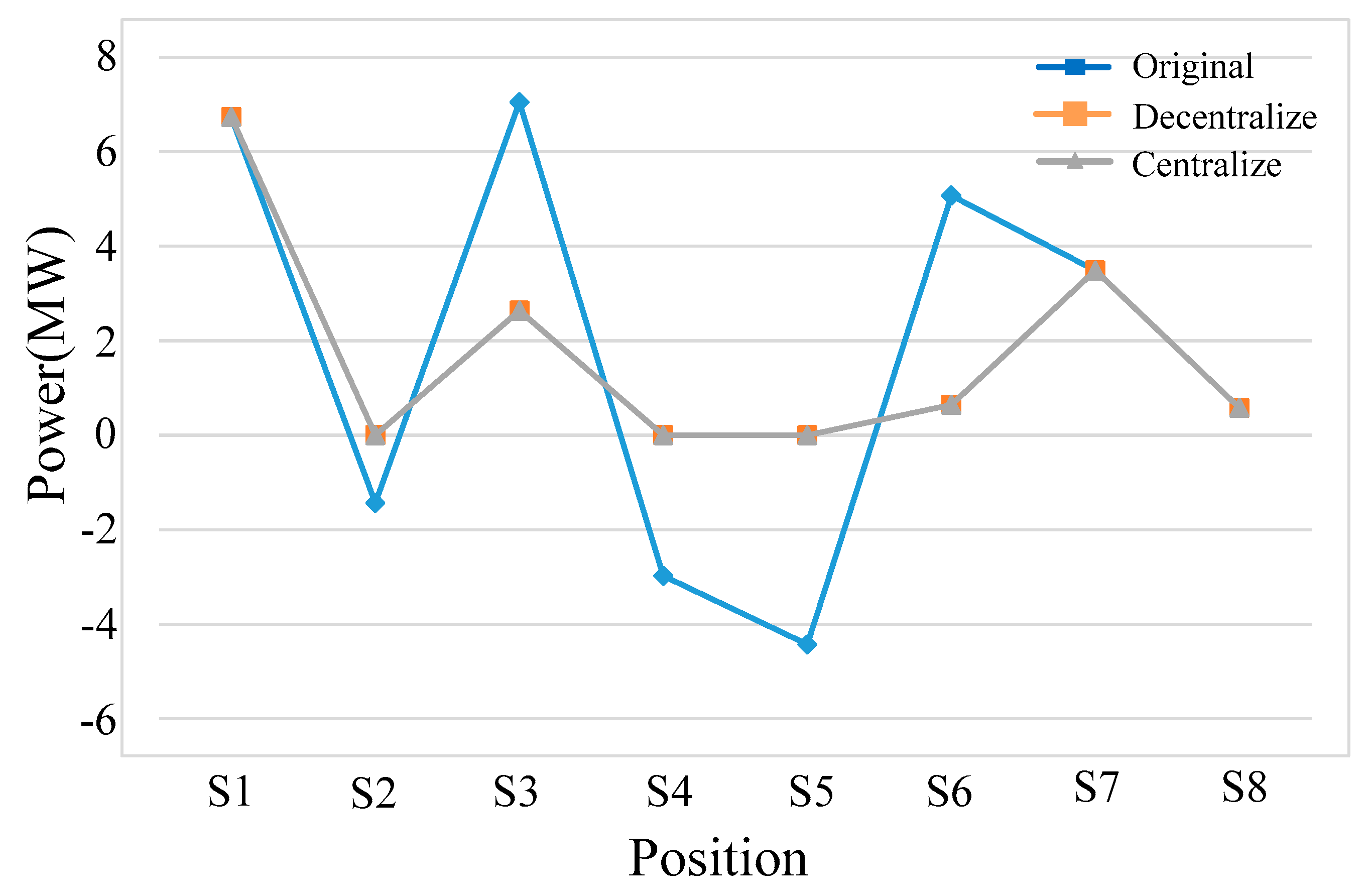
| Model | S1 | S2 | S3 | S4 | S5 | S6 | S7 | S8 |
|---|---|---|---|---|---|---|---|---|
| Original | 6.73437 | −1.43498 | 7.04752 | −2.97820 | −4.43249 | 5.07277 | 3.48401 | 0.57940 |
| Decentralize | 6.73437 | 0 | 2.63433 | 0 | 0 | 0.64028 | 3.48401 | 0.57940 |
| Centralize | 6.73437 | 0 | 2.63433 | 0 | 0 | 0.64028 | 3.48401 | 0.57940 |
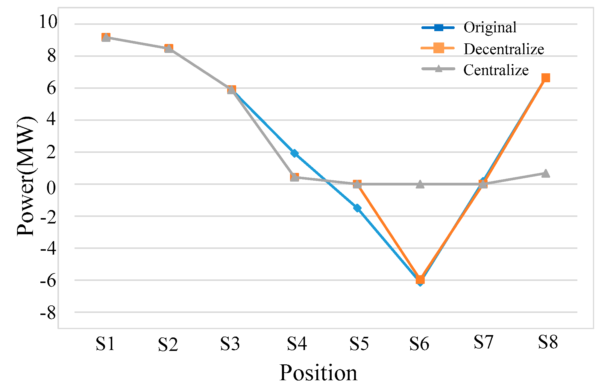
| Model | S1 | S2 | S3 | S4 | S5 | S6 | S7 | S8 |
|---|---|---|---|---|---|---|---|---|
| Original | 9.16775 | 8.47103 | 5.89990 | 1.92519 | −1.49251 | −6.13010 | 0.16504 | 6.64295 |
| Decentralize | 9.16775 | 8.47103 | 5.89990 | 0.43268 | 0 | −5.96506 | 0 | 6.64295 |
| Centralize | 9.16775 | 8.47103 | 5.89990 | 0.43268 | 0 | 0 | 0 | 0.67789 |
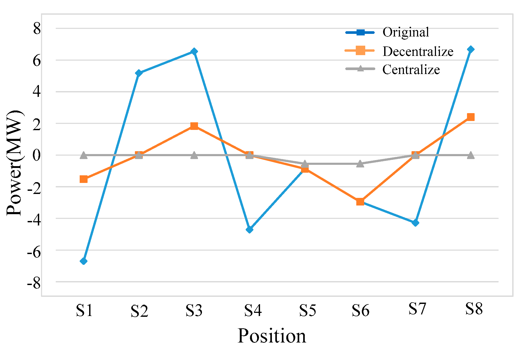
| Model | S1 | S2 | S3 | S4 | S5 | S6 | S7 | S8 |
|---|---|---|---|---|---|---|---|---|
| Original | −6.69996 | 5.17845 | 6.54117 | −4.70942 | −0.86237 | −2.94798 | −4.27674 | 6.68117 |
| Decentralize | −1.52151 | 0 | 1.83175 | 0 | −0.86237 | −2.94798 | 0 | 2.40443 |
| Centralize | 0 | 0 | 0 | 0 | −0.55213 | −0.54355 | 0 | 0 |
© 2020 by the authors. Licensee MDPI, Basel, Switzerland. This article is an open access article distributed under the terms and conditions of the Creative Commons Attribution (CC BY) license (http://creativecommons.org/licenses/by/4.0/).
Share and Cite
Lu, Q.; Gao, Z.; He, B.; Che, C.; Wang, C. Centralized-Decentralized Control for Regenerative Braking Energy Utilization and Power Quality Improvement in Modified AC-Fed Railways. Energies 2020, 13, 2582. https://doi.org/10.3390/en13102582
Lu Q, Gao Z, He B, Che C, Wang C. Centralized-Decentralized Control for Regenerative Braking Energy Utilization and Power Quality Improvement in Modified AC-Fed Railways. Energies. 2020; 13(10):2582. https://doi.org/10.3390/en13102582
Chicago/Turabian StyleLu, Qiwei, Zhixuan Gao, Bangbang He, Cheng Che, and Cong Wang. 2020. "Centralized-Decentralized Control for Regenerative Braking Energy Utilization and Power Quality Improvement in Modified AC-Fed Railways" Energies 13, no. 10: 2582. https://doi.org/10.3390/en13102582
APA StyleLu, Q., Gao, Z., He, B., Che, C., & Wang, C. (2020). Centralized-Decentralized Control for Regenerative Braking Energy Utilization and Power Quality Improvement in Modified AC-Fed Railways. Energies, 13(10), 2582. https://doi.org/10.3390/en13102582