Analysis of Magnetic Field and Torque Features of Improved Permanent Magnet Rotor Deflection Type Three-Degree-of-Freedom Motor


Abstract
:
1. Introduction
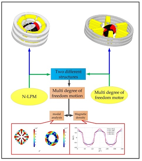
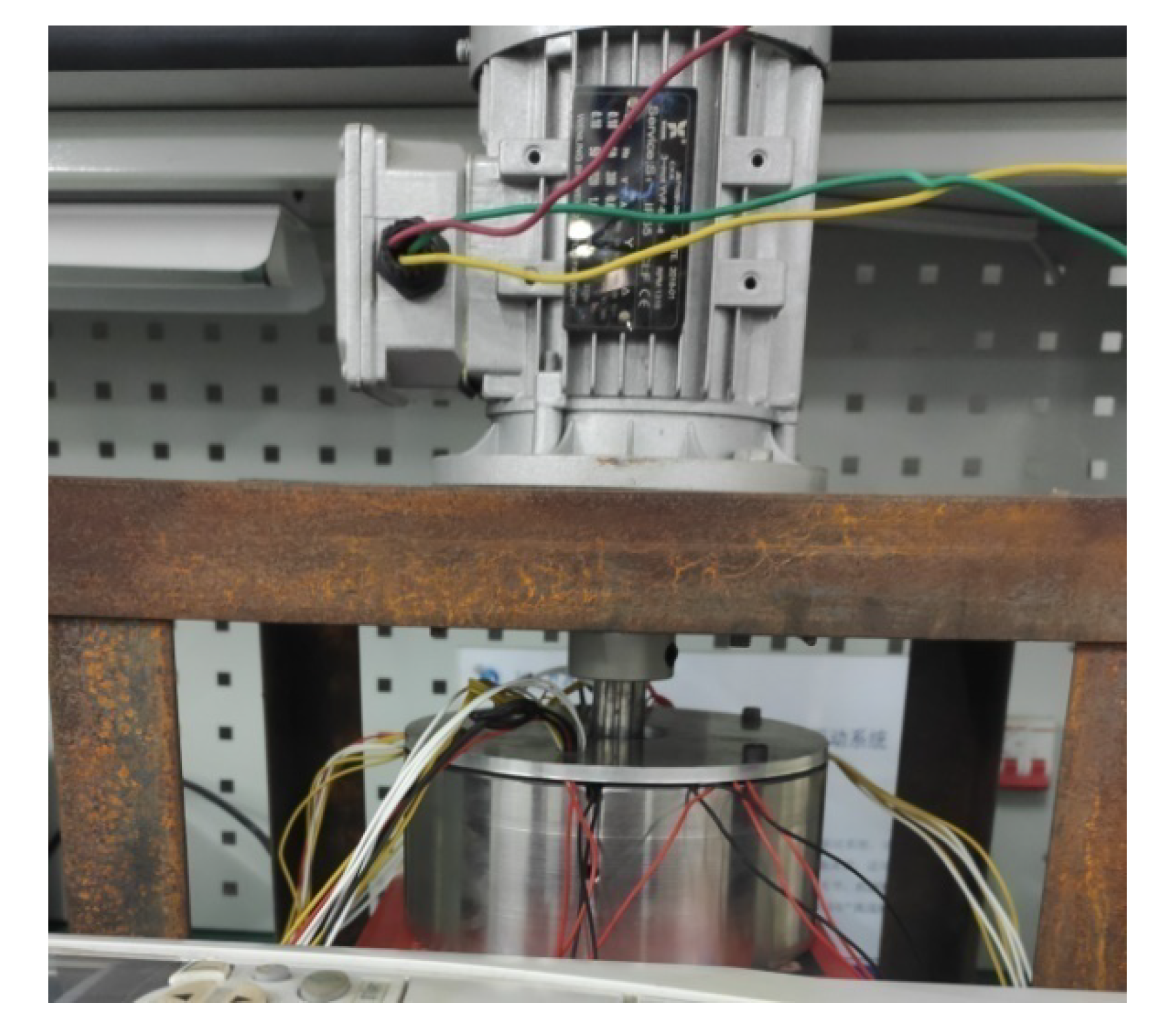
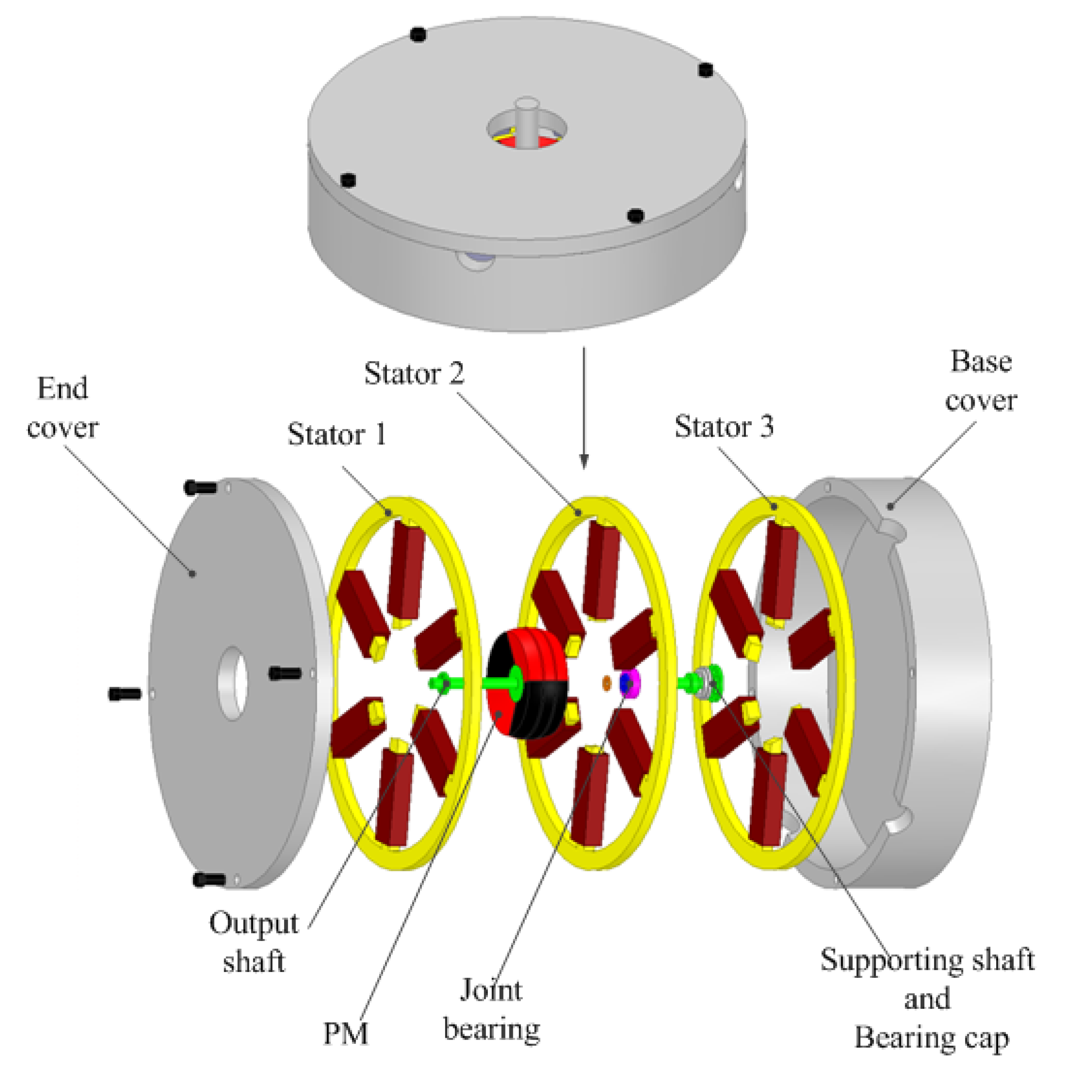
2. Motor Structure
3. Analysis of Stator Model before and after Improvement
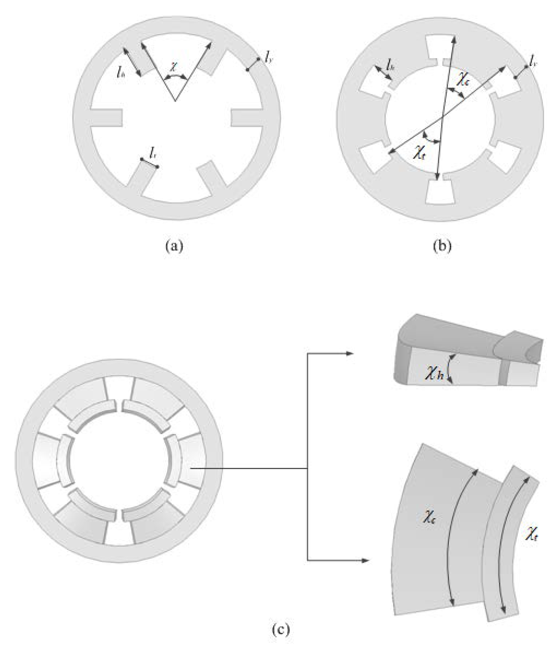
3.1. Introduction to Improved Stator
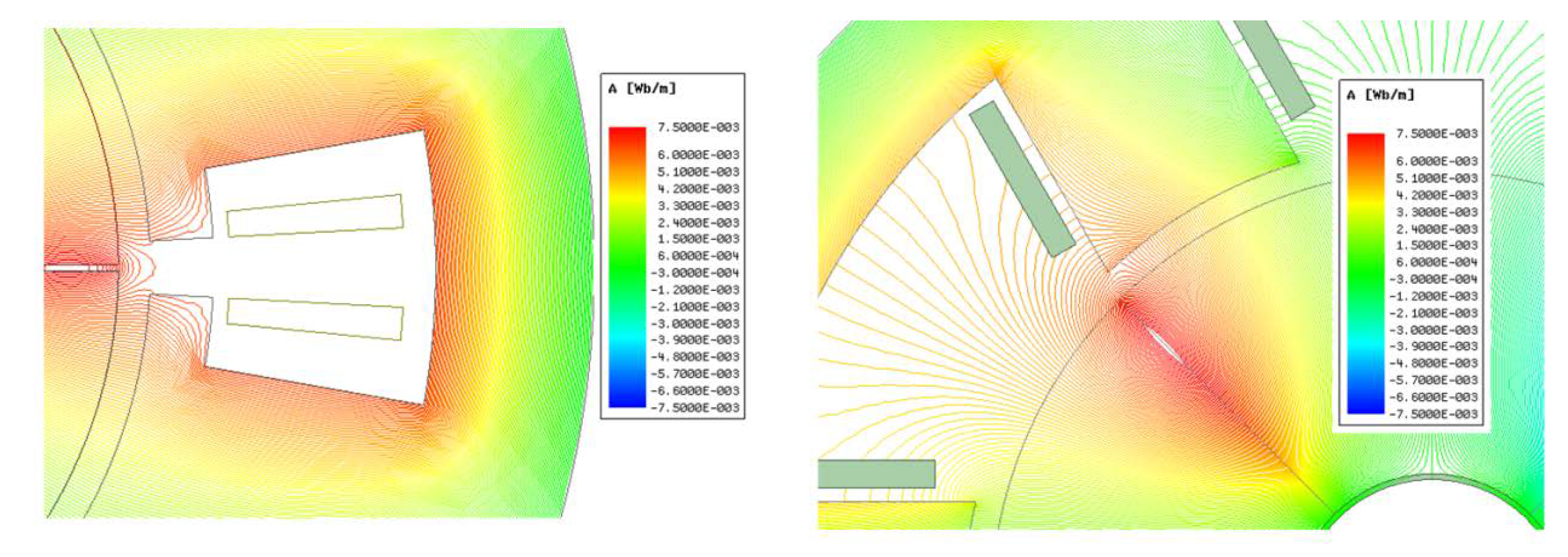
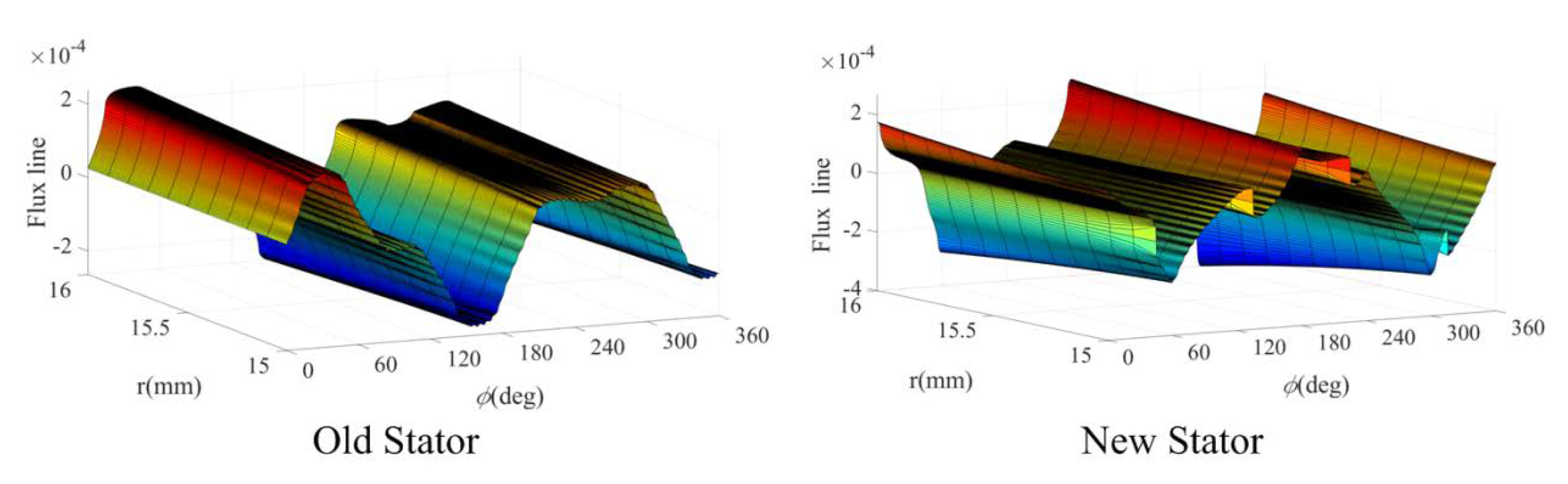
3.2. Improved Magnetic Field Flux Line Comparison
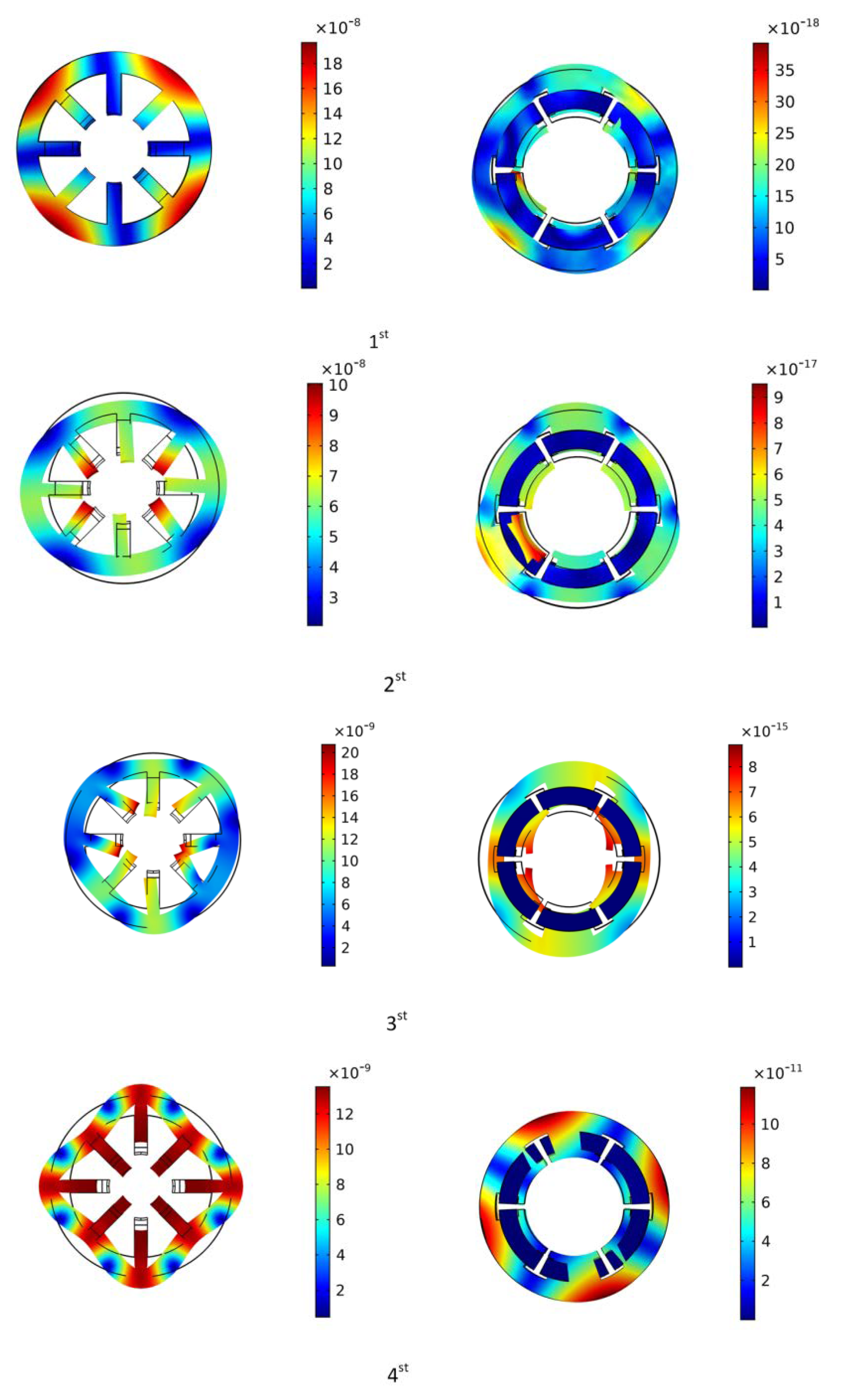
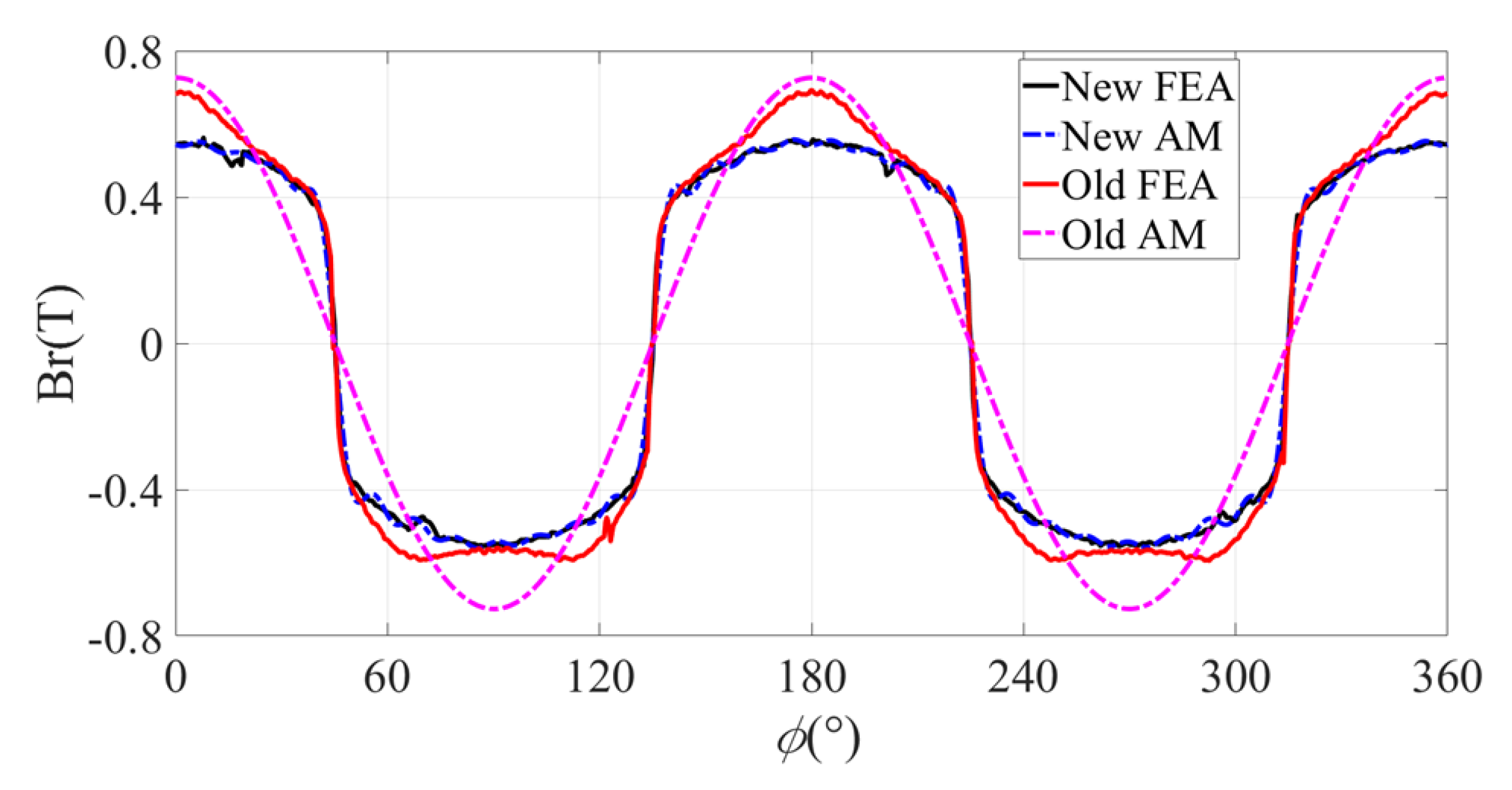
3.3. Stator Magnetic Field Comparison
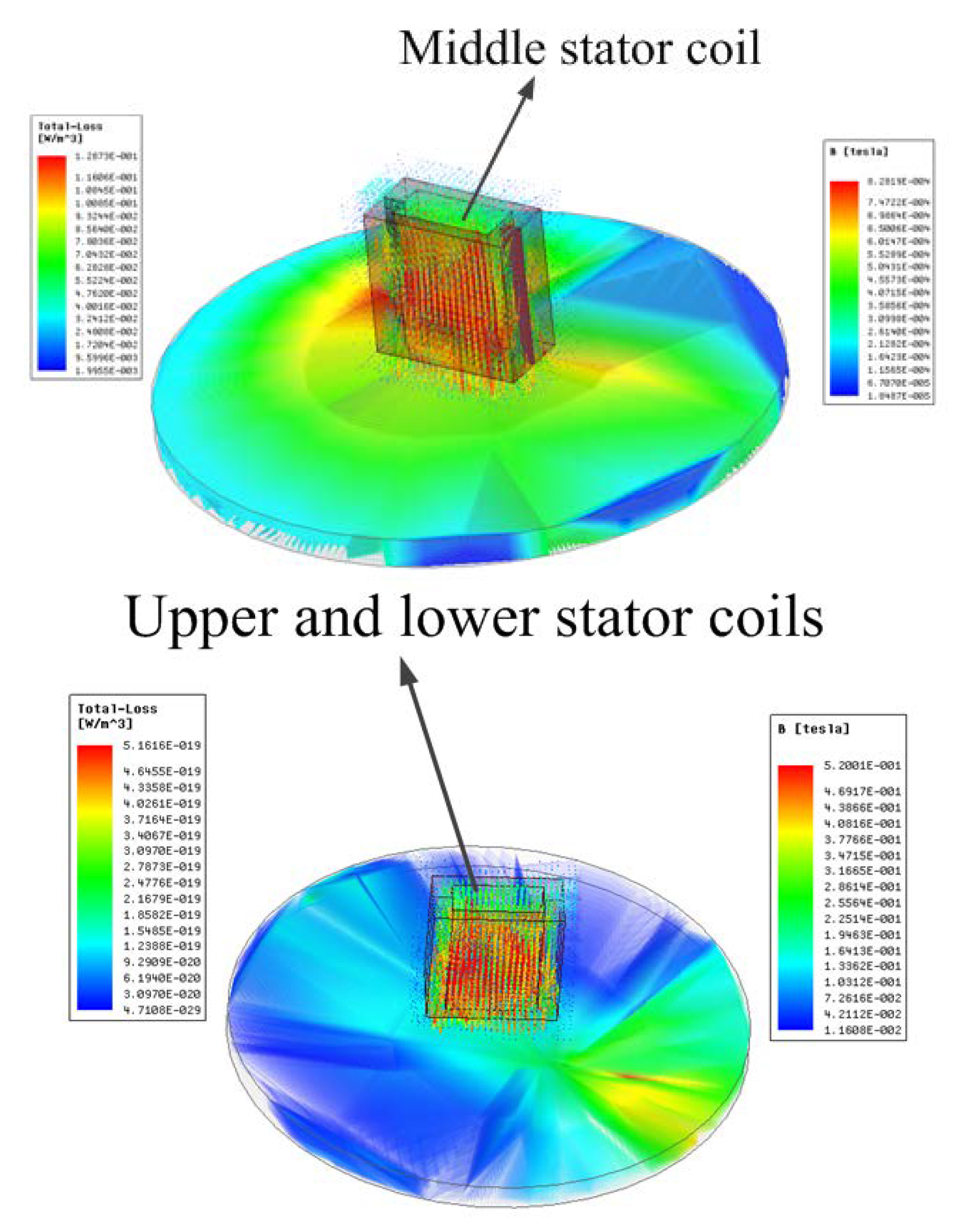
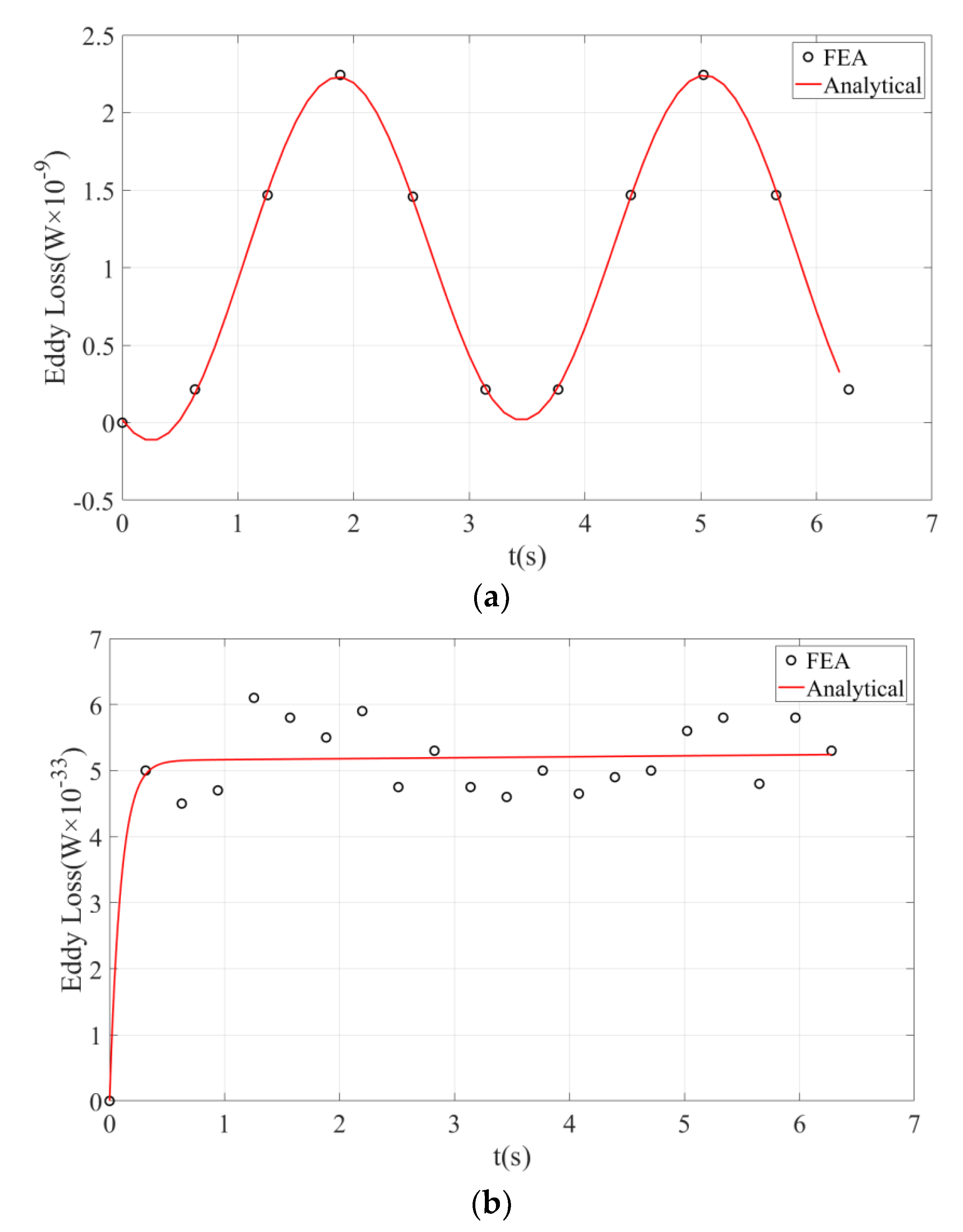
3.4. Study on Stability of Improved Stator Structure
4. Analysis of Rotor Improvement
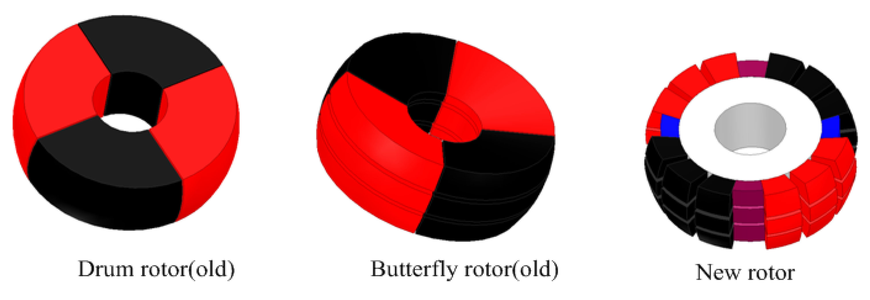
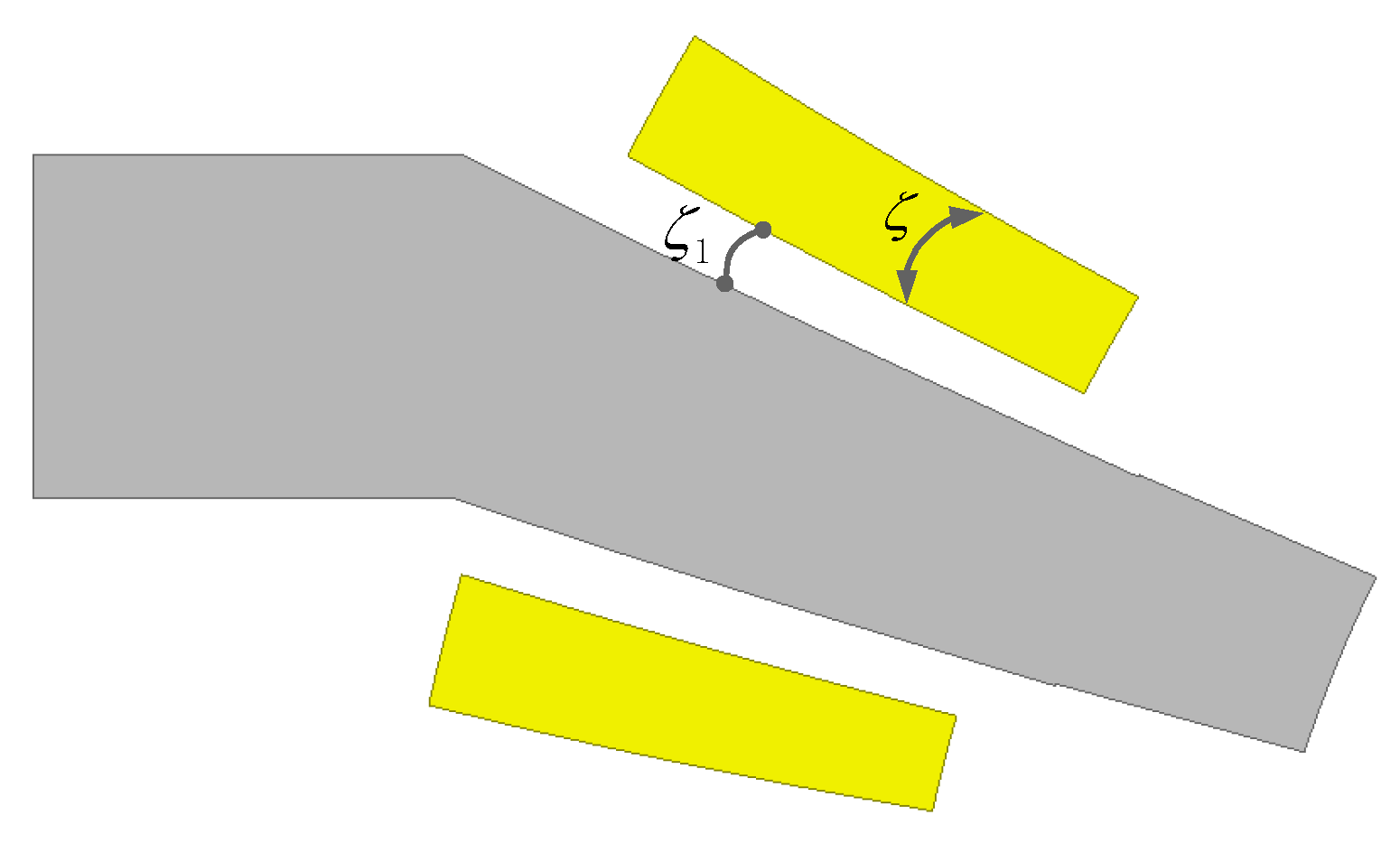
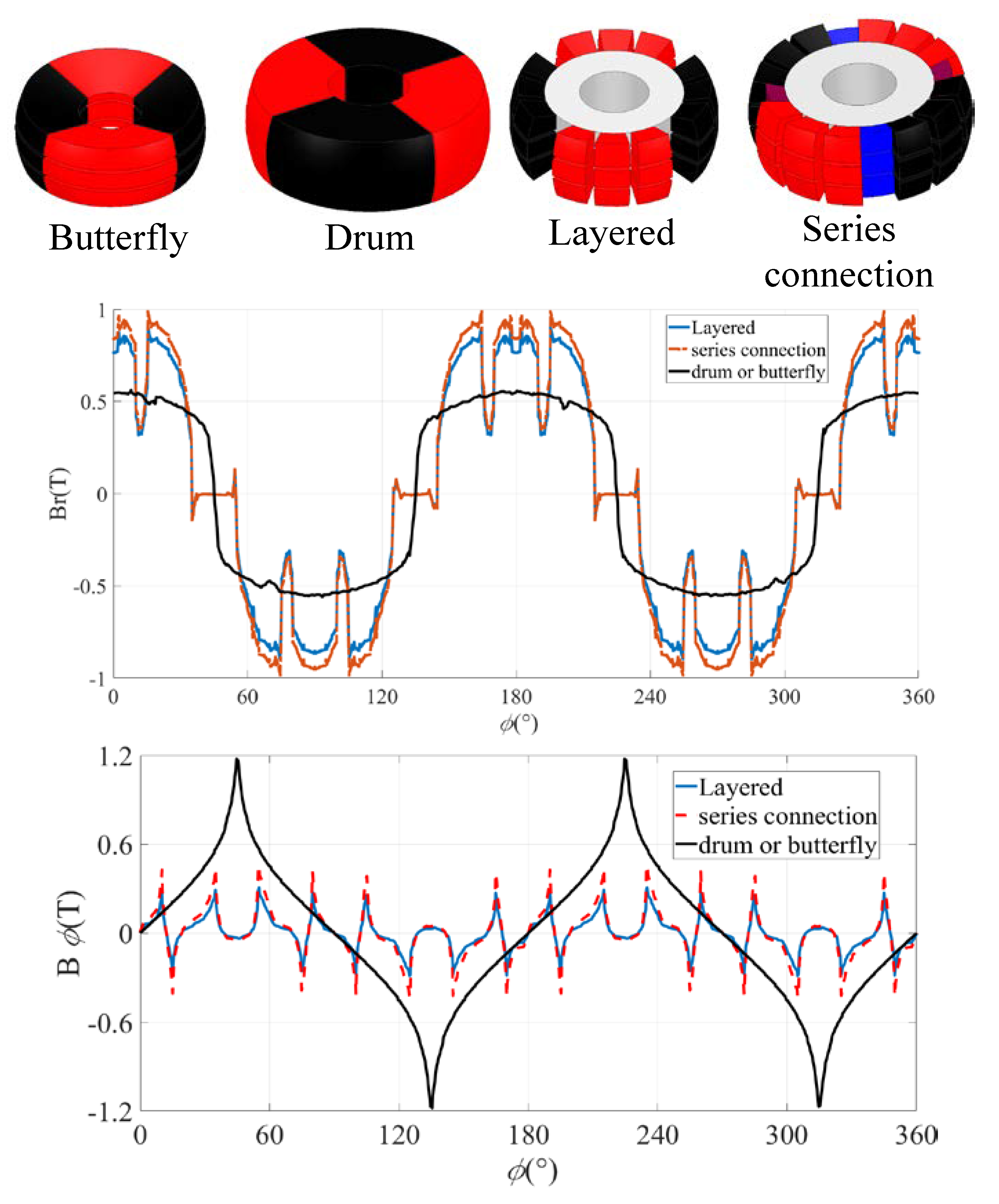
4.1. Introduction to Rotor Structure
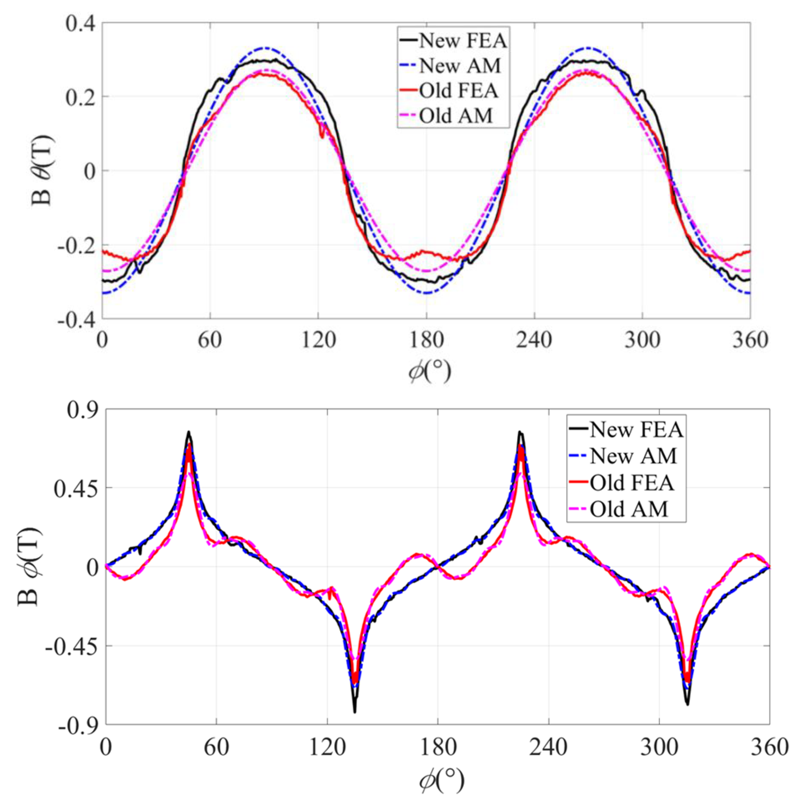
4.2. Magnetic Field of Rotor
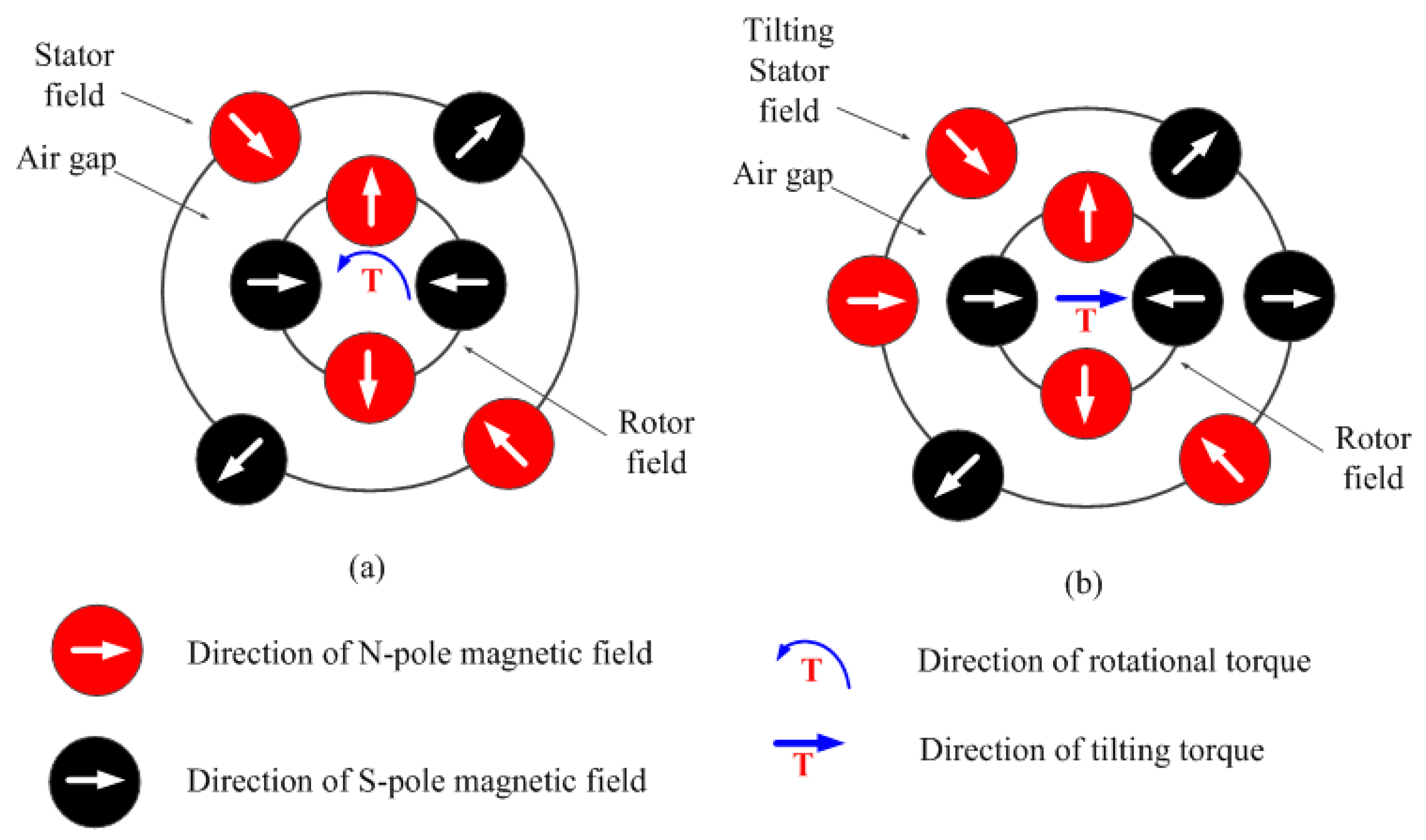
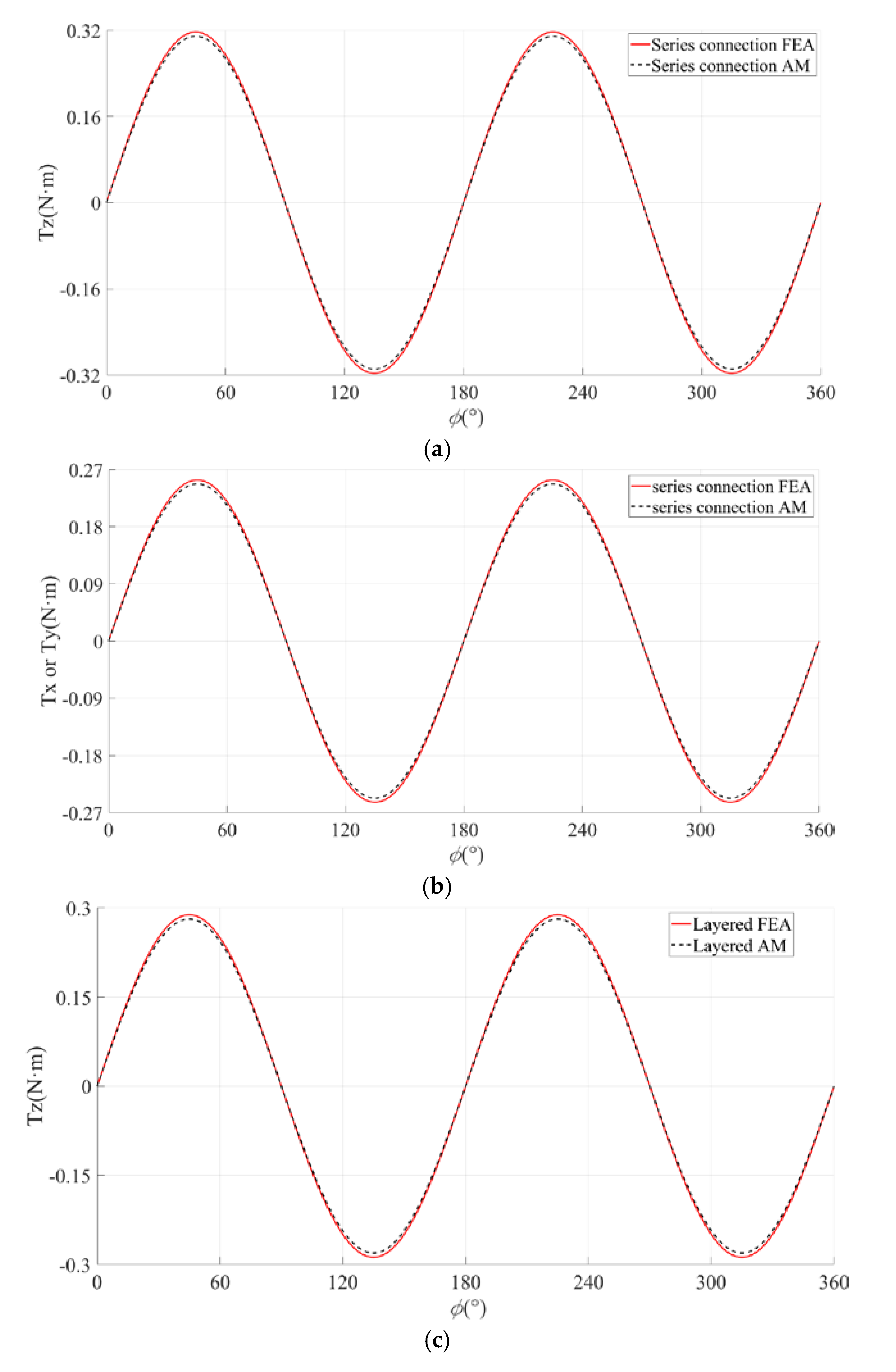
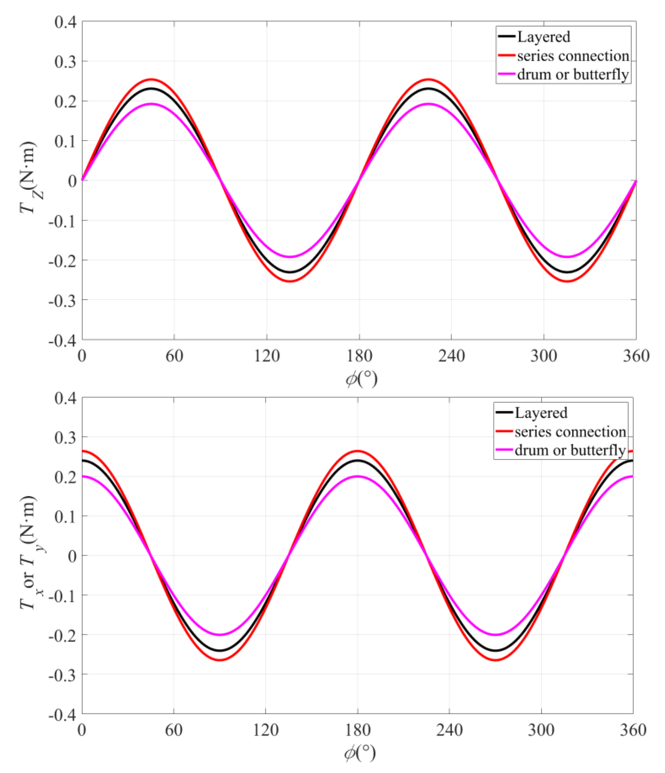
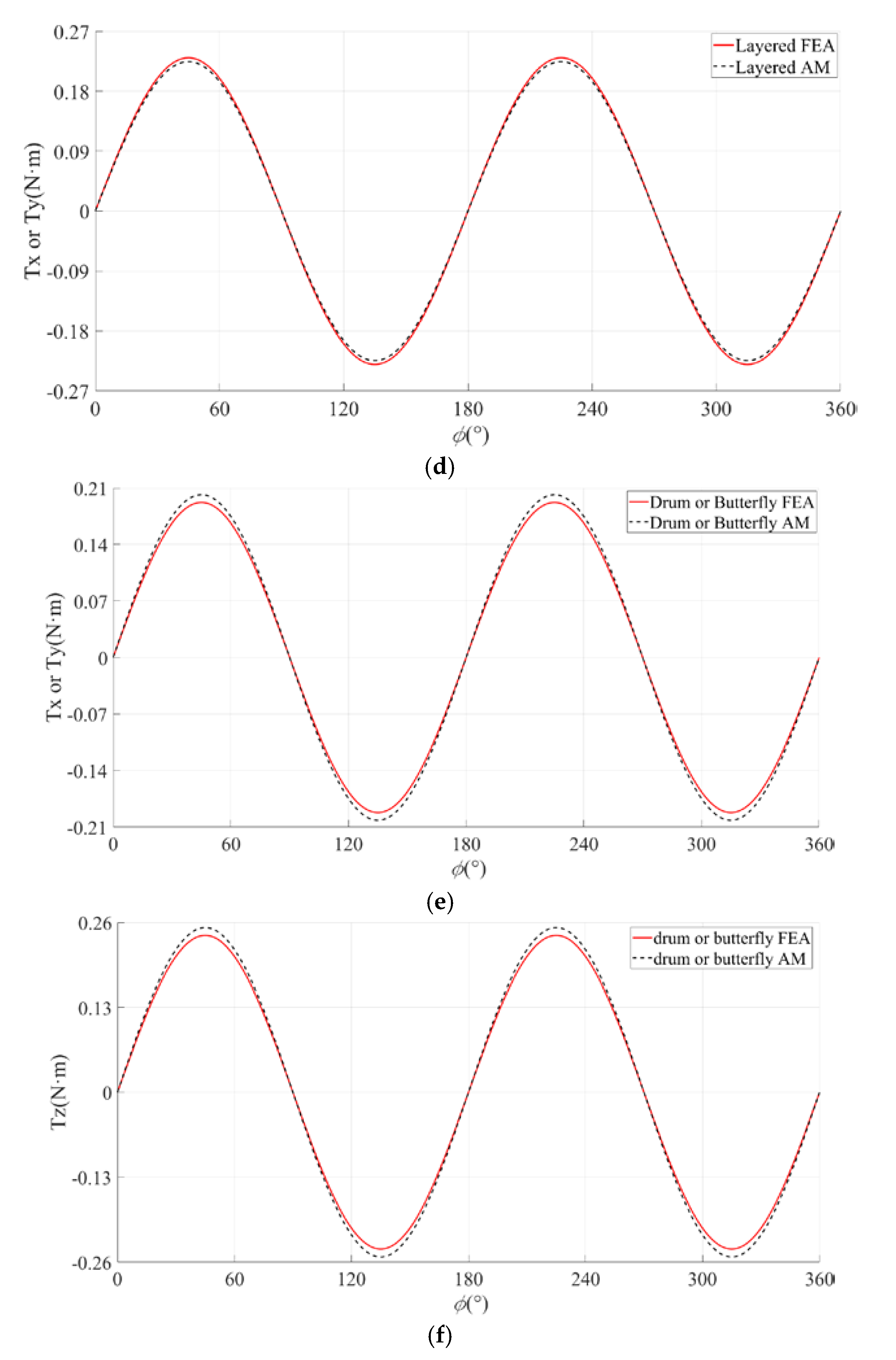
4.3. Analysis of Motor Torque
5. Conclusions
Author Contributions
Funding
Conflicts of Interest
References
- Li, Z. Robust Control of PM Spherical Stepper Motor Based on Neural Networks. IEEE Trans. Ind. Electron. 2009, 56, 2945–2954. [Google Scholar]
- Xia, C.; Guo, C.; Shi, T. A Neural-Network-Identifier and Fuzzy-Controller-Based Algorithm for Dynamic Decoupling Control of Permanent-Magnet Spherical Motor. IEEE Trans. Ind. Electron. 2010, 57, 2868–2878. [Google Scholar]
- Lim, C.K.; Chen, I.M.; Yan, L.; Yang, G.; Lee, K.M. Electromechanical Modeling of a Permanent-Magnet Spherical Actuator Based on Magnetic-Dipole-Moment Principle. IEEE Trans. Ind. Electron. 2009, 56, 1640–1648. [Google Scholar]
- Hong, H.S.; Won, S.H.; Lee, H.W.; Bae, J.N.; Lee, J. Design of Torque Actuator in Hybrid Multi-DOF System Considering Magnetic Saturation. IEEE Trans. Magn. 2015, 51, 1–4. [Google Scholar] [CrossRef]
- Kwon, B.-I.; Kim, Y.-B. Design and Analysis of Double Excited 3-Degree-of-Freedom Motor for Robots. J. Electr. Eng. Technol. 2011, 6, 618–625. [Google Scholar] [CrossRef] [Green Version]
- Fernades, J.F.P.; Branco, P.J.C. The Shell-Like Spherical Induction Motor for Low-Speed Traction: Electromagnetic Design, Analysis, and Experimental Tests. IEEE Trans. Ind. Electron. 2016, 63, 4325–4335. [Google Scholar] [CrossRef]
- Bai, K.; Lee, K.-M. Direct Field-Feedback Control of a Ball-Joint-Like Permanent-Magnet Spherical Motor. IEEE/ASME Trans. Mechatron. 2014, 19, 975–986. [Google Scholar] [CrossRef]
- Tsukano, M.; Sakaidani, Y.; Hirata, K.; Niguchi, N.; Maeda, S.; Zaini, A. Analysis of 2-Degree of Freedom Outer Rotor Spherical Actuator Employing 3-D Finite Element Method. IEEE Trans. Magn. 2013, 49, 2233–2236. [Google Scholar] [CrossRef]
- Kim, H.Y.; Kim, H.; Gweon, D.-G.; Jeong, J. Development of a Novel Spherical Actuator with Two Degrees of Freedom. IEEE/ASNE Trans. Mechatron. 2015, 20, 532–540. [Google Scholar] [CrossRef]
- Cho, S.; Lim, J.-S.; Oh, Y.J.; Jeong, G.; Kang, D.-W.; Lee, H.-J. A Study on Output Characteristics of the Spherical Multi-DOF Motor According to the Number of Phases and Pole Pitch Angles. IEEE Trans. Magn. 2018, 54, 1–5. [Google Scholar] [CrossRef]
- Shi, T.; Song, P.; Li, H.; Xia, C. End-effect of the permanent-magnet spherical motor and its influence on back-EMF characteristics. Sci. China 2012, 55, 206–212. [Google Scholar] [CrossRef]
- Li, Z.; Zhi, R.; Wang, Q. Analysis of 2-Degree of Freedom Outer Rotor Spherical Actuator Employing 3-D Finite Element Method. Tehnicki Vjesnik-Technical Gazette 2017, 24, 249–256. [Google Scholar]
- Fang, J.; Xu, S. Effects of Eddy Current in Electrical Connection Surface of Laminated Cores on High-Speed PM Motor Supported by Active Magnetic Bearings. IEEE Trans. Magn. 2015, 51, 1–4. [Google Scholar] [CrossRef]
- Findlay, R.D.; Stranges, N. Skin Effect Factor in the Bar Extension of Large Two-Pole Induction Motors by Three-Dimensional Finite-Element Simulations. IEEE Trans. Magn. 2006, 42, 3404–3406. [Google Scholar]
- Tsukada, K.; Majima, Y.; Nakamura, Y.; Yasugi, T.; Song, N.; Sakai, K.; Kiwa, T. Detection of Inner Cracks in Thick Steel Plates Using Unsaturated AC Magnetic Flux Leakage Testing with a Magnetic Resistance Gradiometer. IEEE Trans. Magn. 2017, 53, 1–5. [Google Scholar] [CrossRef]
- Gan, L.; Pei, Y.; Chai, F. Tilting Torque Calculation of a Novel Tiered Type Permanent Magnet Spherical Motor. IEEE Trans. Ind. Electron. 2019, 67, 421–431. [Google Scholar] [CrossRef]
- Cai, W.; Pillay, P.; Tang, Z.; Omekanda, A. Low-vibration design of switched reluctance motors for automotive applications using modal analysis. IEEE Trans. Ind. Appl. 2003, 39, 971–977. [Google Scholar] [CrossRef]
- Shin, H.-J.; Choi, J.-Y.; Park, H.-I.; Jang, S.-M. Vibration Analysis and Measurements Through Prediction of Electromagnetic Vibration Sources of Permanent Magnet Synchronous Motor Based on Analytical Magnetic Field Calculations. IEEE Trans. Magn. 2012, 48, 4216–4219. [Google Scholar] [CrossRef]
- Li, Z.; He, W.; Liu, L.; Wang, Q. Magnetic Field Calculation and Dynamics Simulation of a Permanent Magnetic Hybrid Driven 3-DOF Motor. J. Electr. Eng. Technol. 2019, 14, 711–718. [Google Scholar] [CrossRef]
- Li, Z.; Guo, P.; Han, R.; Wang, Q. Torque modeling and characteristic analysis of electromagnetic piezoelectric hybrid-driven 3-degree-of-freedom motor. Adv. Mech. Eng. 2018, 10, 1–15. [Google Scholar] [CrossRef] [Green Version]


| Parameter | Drum | Butterfly | Layered | Series | Optimization Rate |
|---|---|---|---|---|---|
| Bmax (T) | 0.55 | 0.57 | 0.9 | 0.99 | 80% |
| Tzmax (B·m) | 0.24 | 0.24 | 0.28 | 0.32 | 25% |
| Txmax (B·m) | 0.2 | 0.205 | 0.25 | 0.28 | 40% |
| Vmag (mm3) | 6021.39 | 5633.66 | 2342.01 | 2732.40 | 54.72% |
| Parameter | Value |
|---|---|
| Out diameter (mm) | 150 |
| Axial length (mm) | 120 |
| PM remanence (T) | 1.15 |
| PM relative permeability | 1.05 |
| Inner diameter (mm) | 75 |
© 2020 by the authors. Licensee MDPI, Basel, Switzerland. This article is an open access article distributed under the terms and conditions of the Creative Commons Attribution (CC BY) license (http://creativecommons.org/licenses/by/4.0/).
Share and Cite
Li, Z.; Yu, X.; Xue, Z.; Sun, H. Analysis of Magnetic Field and Torque Features of Improved Permanent Magnet Rotor Deflection Type Three-Degree-of-Freedom Motor. Energies 2020, 13, 2533. https://doi.org/10.3390/en13102533
Li Z, Yu X, Xue Z, Sun H. Analysis of Magnetic Field and Torque Features of Improved Permanent Magnet Rotor Deflection Type Three-Degree-of-Freedom Motor. Energies. 2020; 13(10):2533. https://doi.org/10.3390/en13102533
Chicago/Turabian StyleLi, Zheng, Xuze Yu, Zengtao Xue, and Hexu Sun. 2020. "Analysis of Magnetic Field and Torque Features of Improved Permanent Magnet Rotor Deflection Type Three-Degree-of-Freedom Motor" Energies 13, no. 10: 2533. https://doi.org/10.3390/en13102533
APA StyleLi, Z., Yu, X., Xue, Z., & Sun, H. (2020). Analysis of Magnetic Field and Torque Features of Improved Permanent Magnet Rotor Deflection Type Three-Degree-of-Freedom Motor. Energies, 13(10), 2533. https://doi.org/10.3390/en13102533