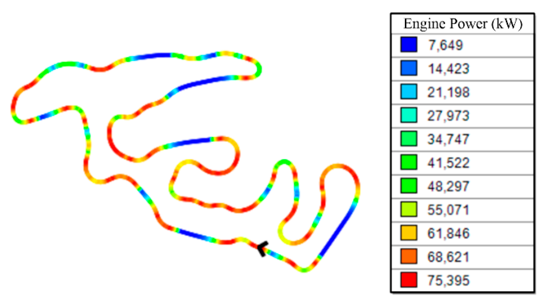
Figure 1.
FSAE autocross Germany track simulation.
Figure 1.
FSAE autocross Germany track simulation.
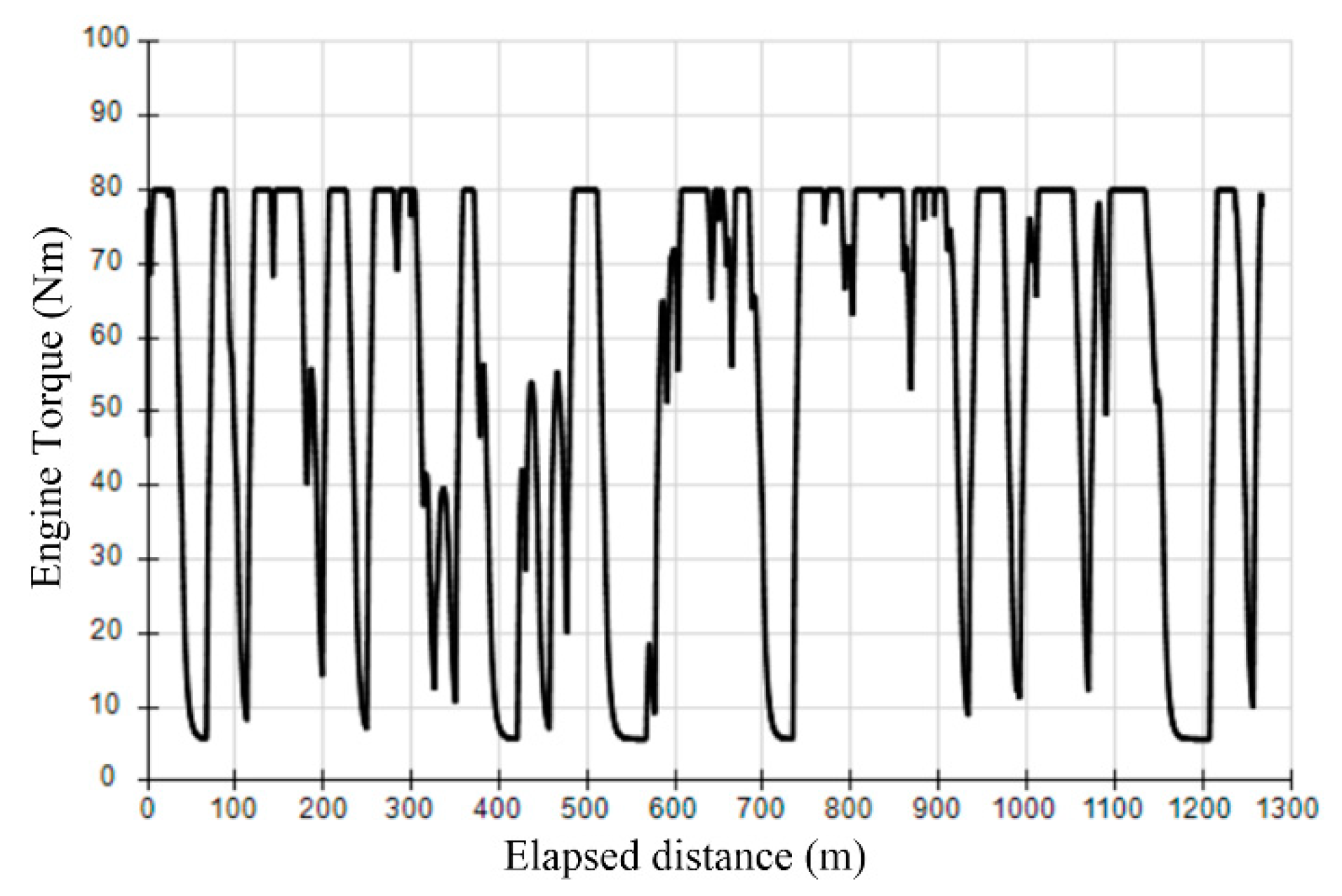
Figure 2.
Instantaneous motor’s torque along the track.
Figure 2.
Instantaneous motor’s torque along the track.
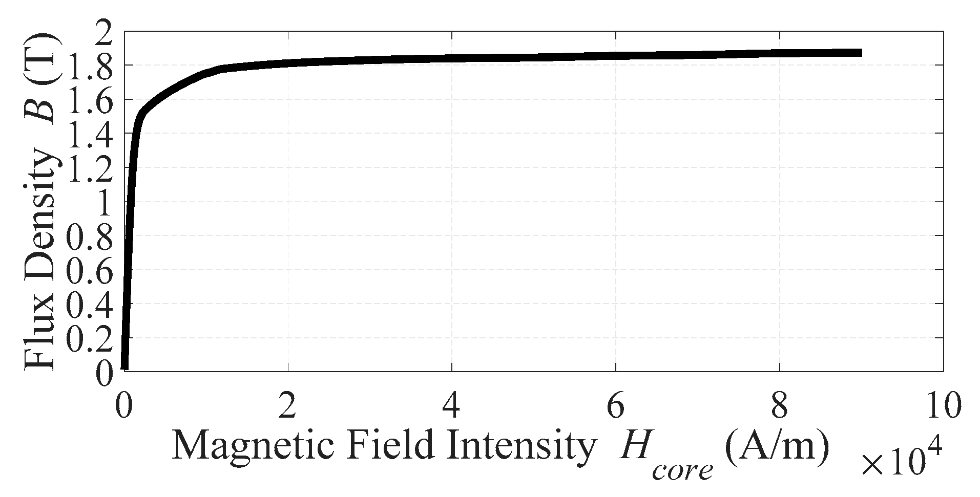
Figure 3.
B-H curve of NGO 35JN200 electrical steel.
Figure 3.
B-H curve of NGO 35JN200 electrical steel.
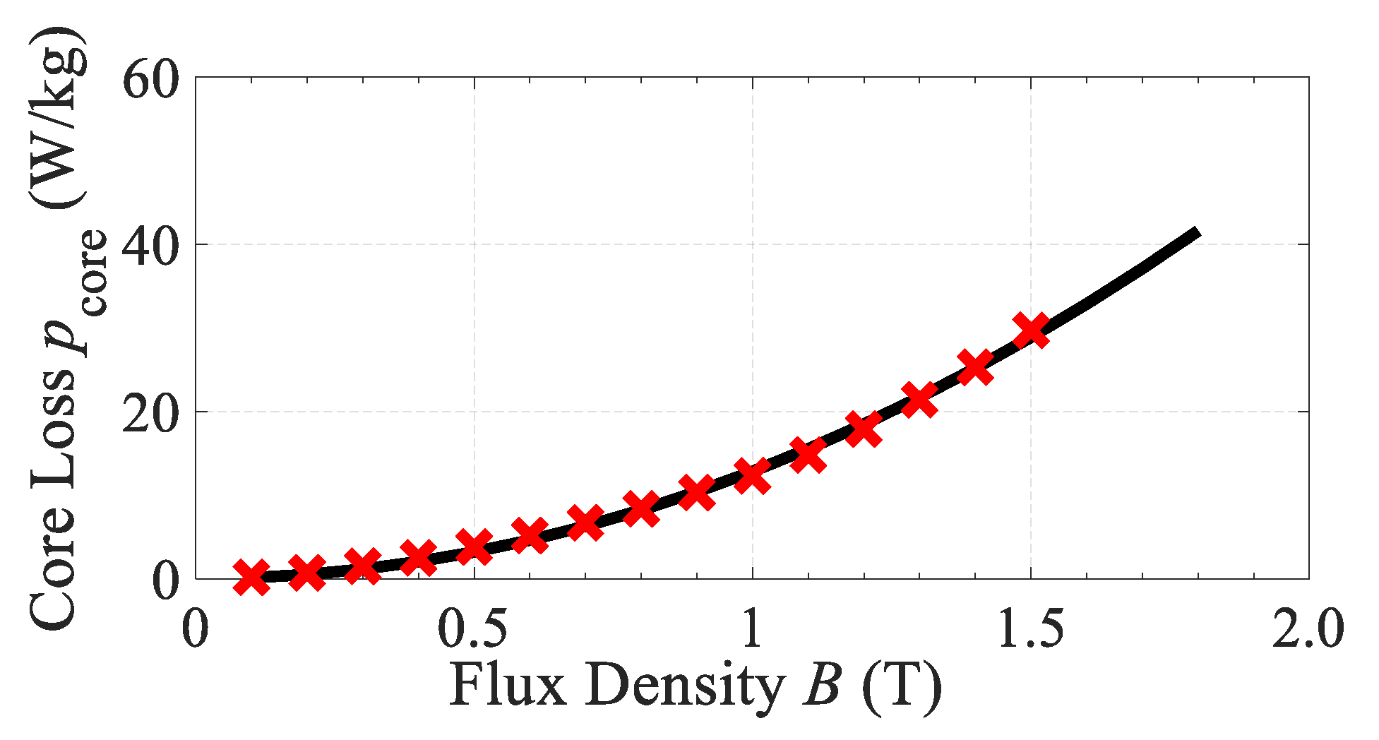
Figure 4.
Core loss curve at 400 Hz of NGO 35JN200 electrical steel.
Figure 4.
Core loss curve at 400 Hz of NGO 35JN200 electrical steel.
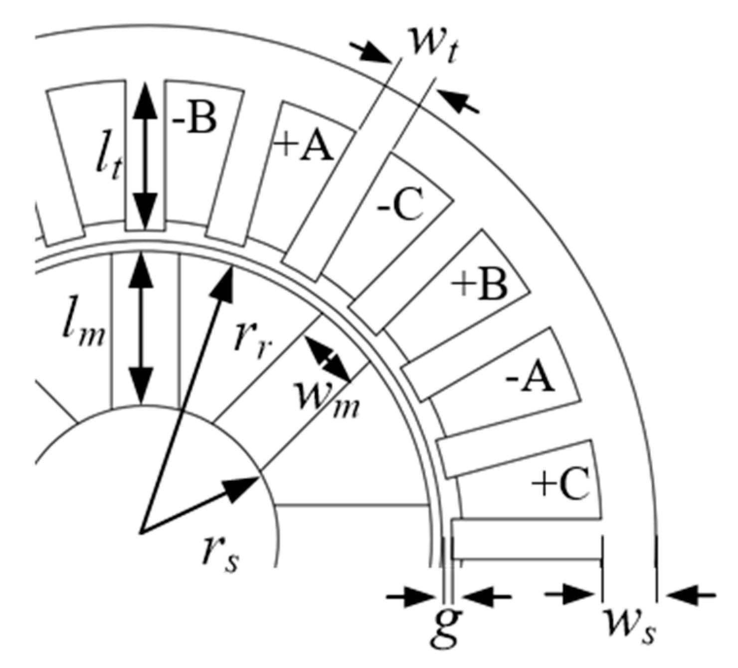
Figure 5.
Interior permanent magnet synchronous machines (IPSM) model geometry with 24 slots.
Figure 5.
Interior permanent magnet synchronous machines (IPSM) model geometry with 24 slots.
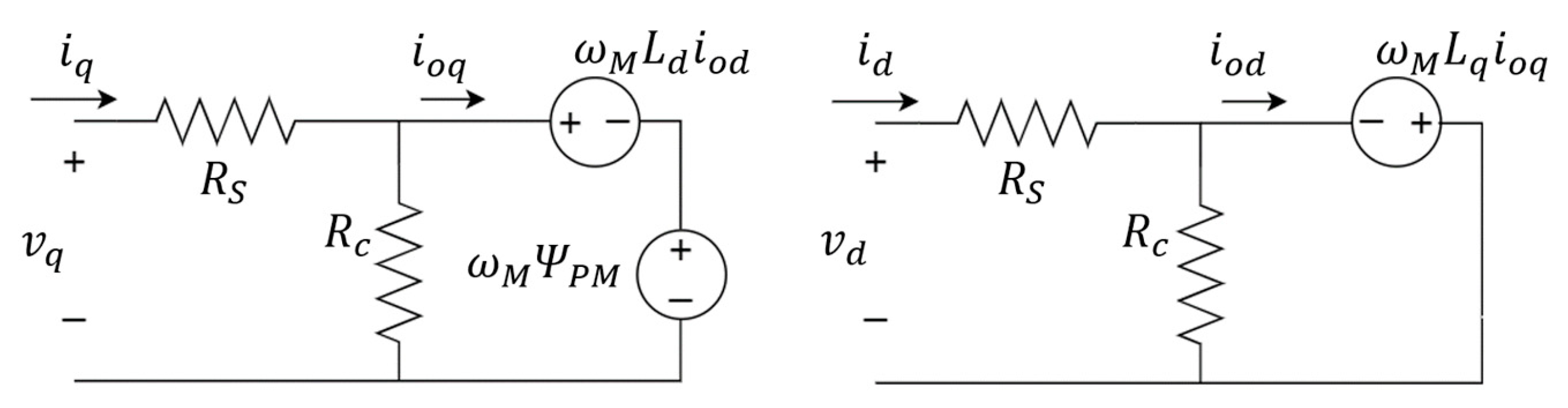
Figure 6.
Synchronous machine equivalent circuit considering core-losses in d-q reference frame.
Figure 6.
Synchronous machine equivalent circuit considering core-losses in d-q reference frame.
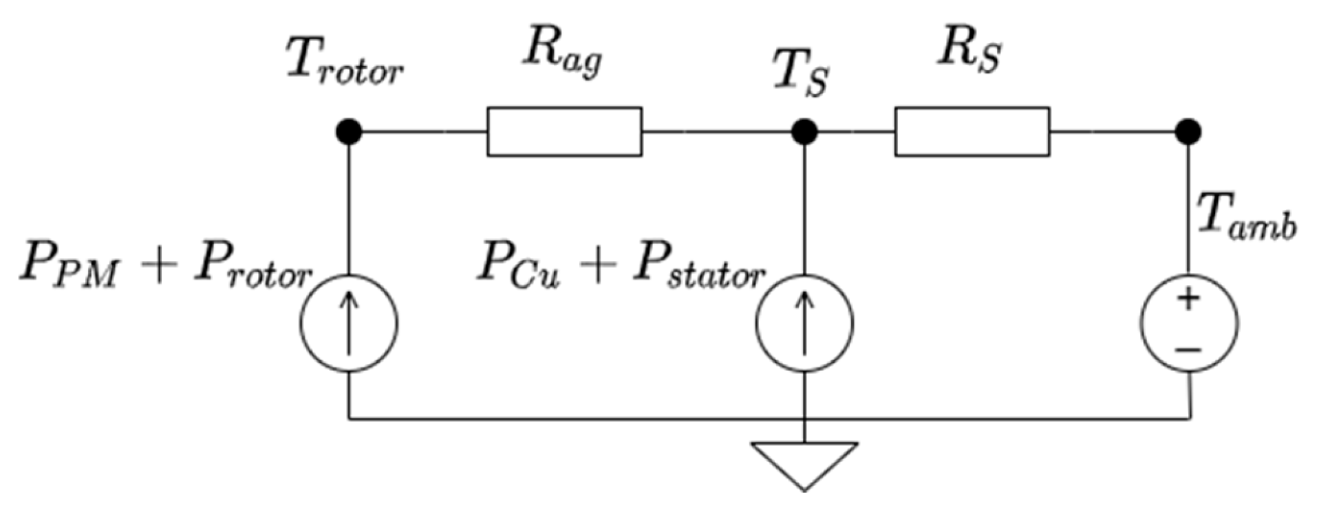
Figure 7.
Thermal circuit used to estimate the maximum operating temperature during optimization.
Figure 7.
Thermal circuit used to estimate the maximum operating temperature during optimization.
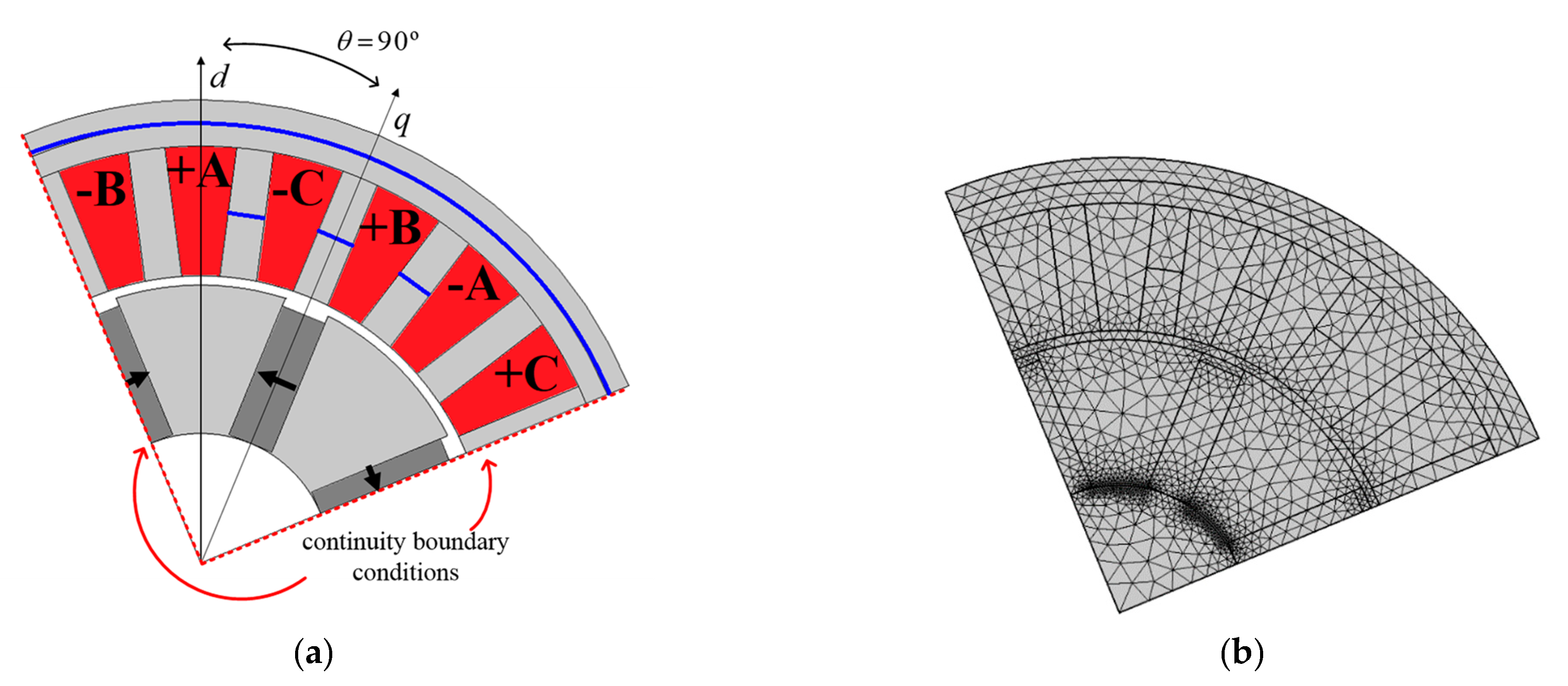
Figure 8.
Finite Element Model of an example geometry (a) representation with the rotor’s q-axis aligned with phase A and (b) used mesh.
Figure 8.
Finite Element Model of an example geometry (a) representation with the rotor’s q-axis aligned with phase A and (b) used mesh.
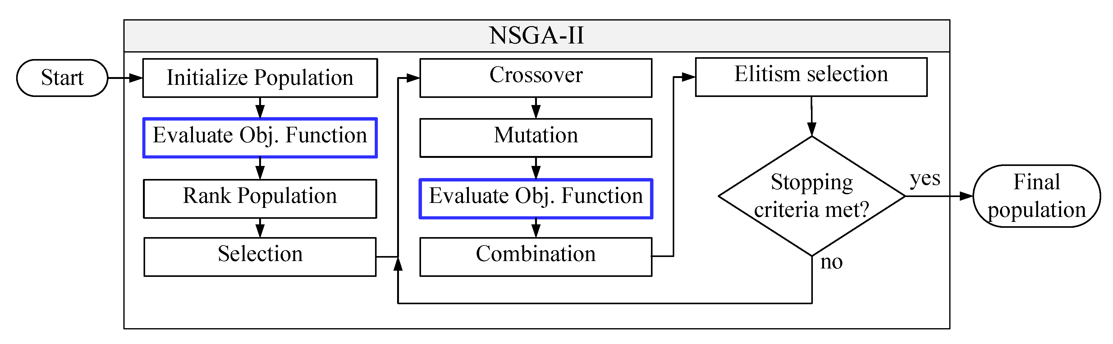
Figure 9.
Non-dominated sorting genetic algorithm II (NSGA-II) process flowchart.
Figure 9.
Non-dominated sorting genetic algorithm II (NSGA-II) process flowchart.
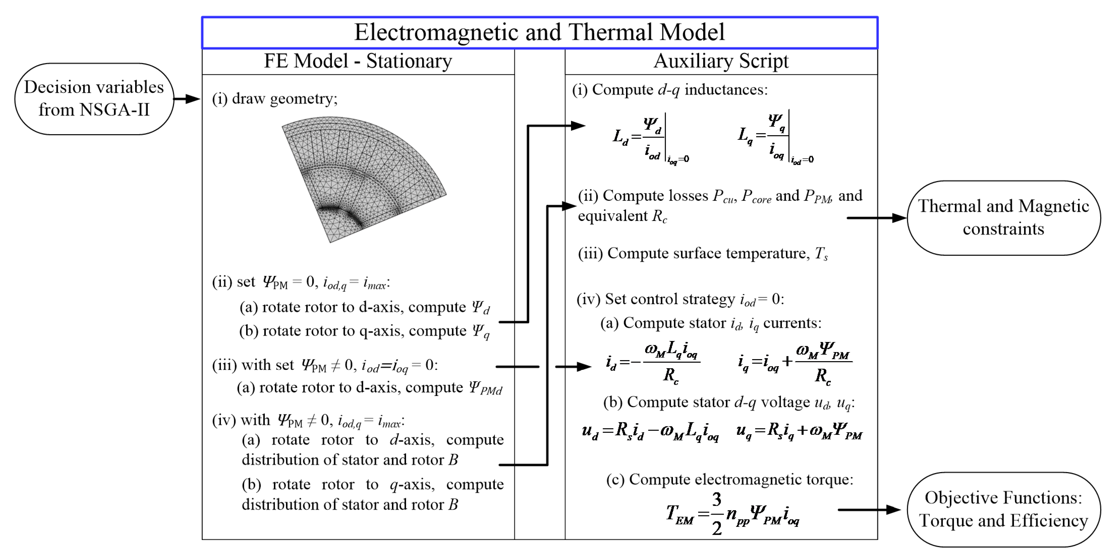
Figure 10.
Objective function evaluation.
Figure 10.
Objective function evaluation.
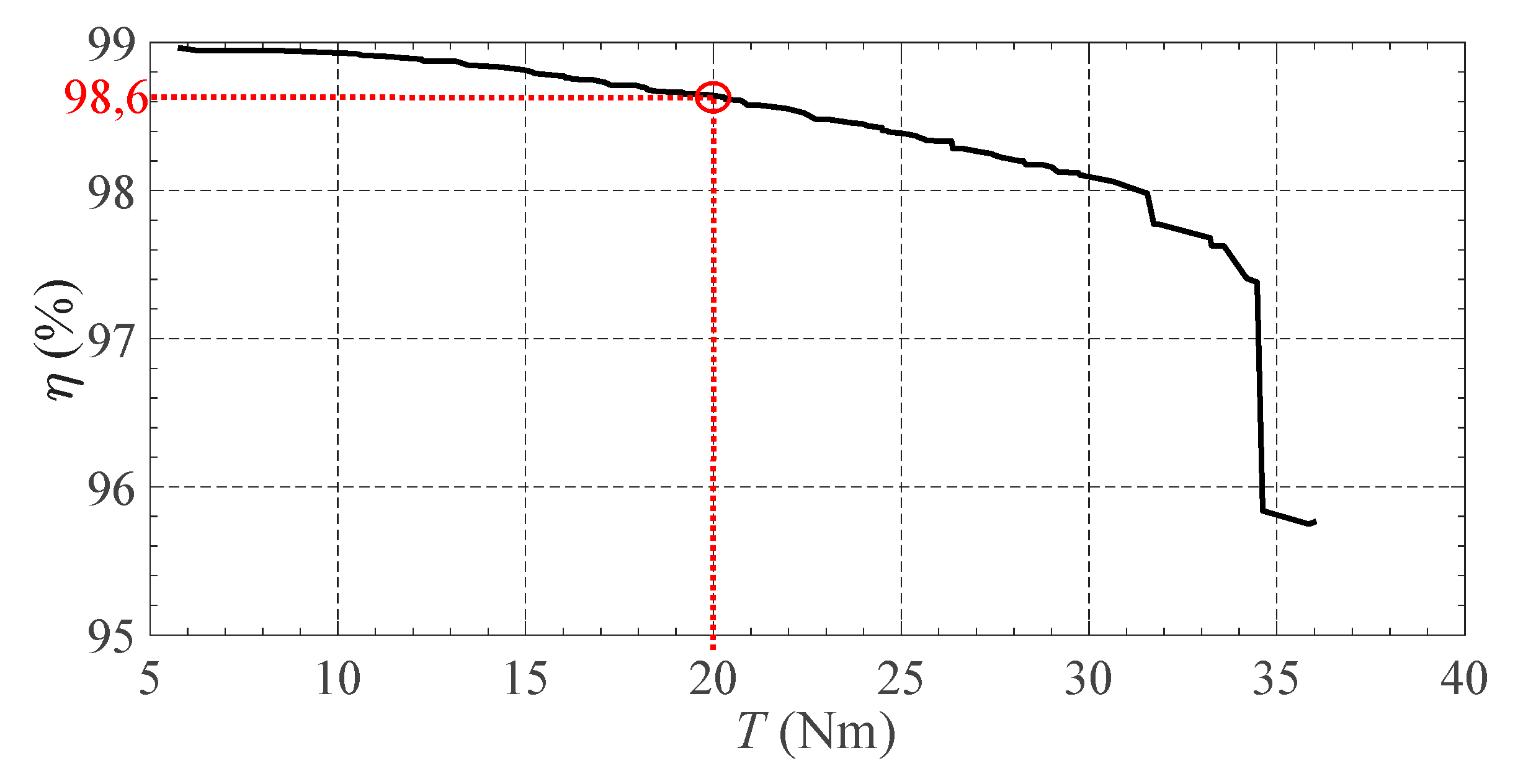
Figure 11.
Pareto front—Objective functions.
Figure 11.
Pareto front—Objective functions.
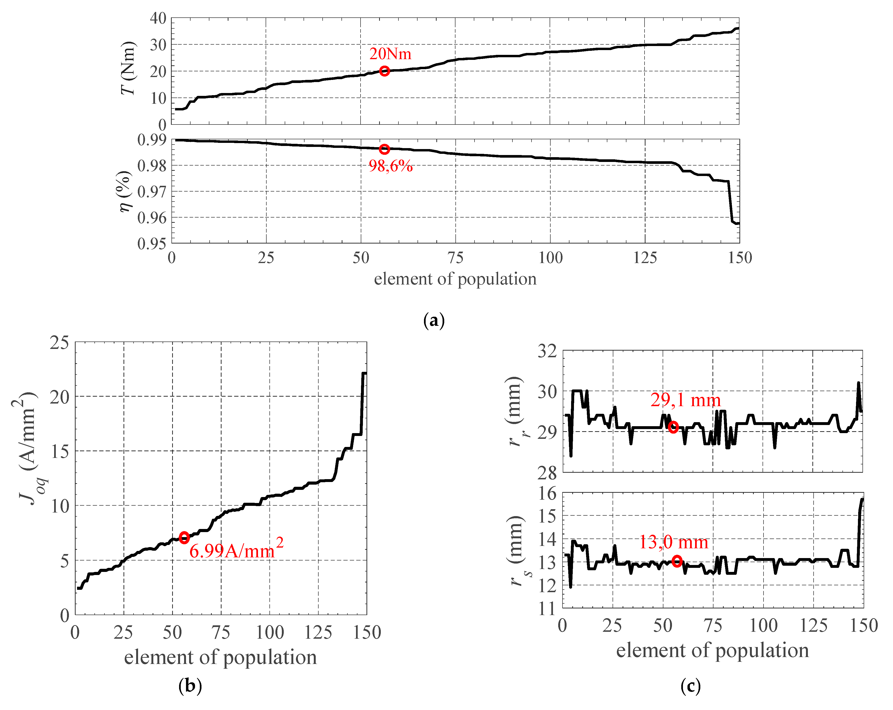
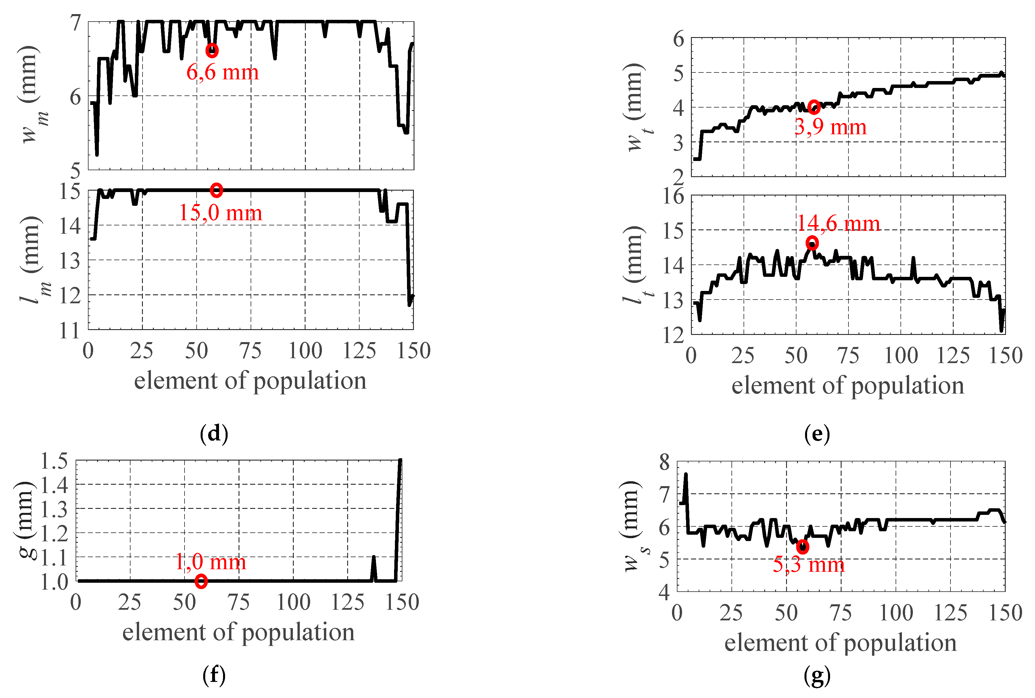
Figure 12.
Pareto front—Objective functions and decision variables. In each figure is shown the evolution, for each element of population, of (a) the torque, T, and efficiency, η, (b) the torque producing current density, , (c) the rotor and shaft radius, and , (d) the magnet width and length, and , (e) the teeth width and length, and , (f) the airgap size, g, and (g) the stator outer ring width, .
Figure 13.
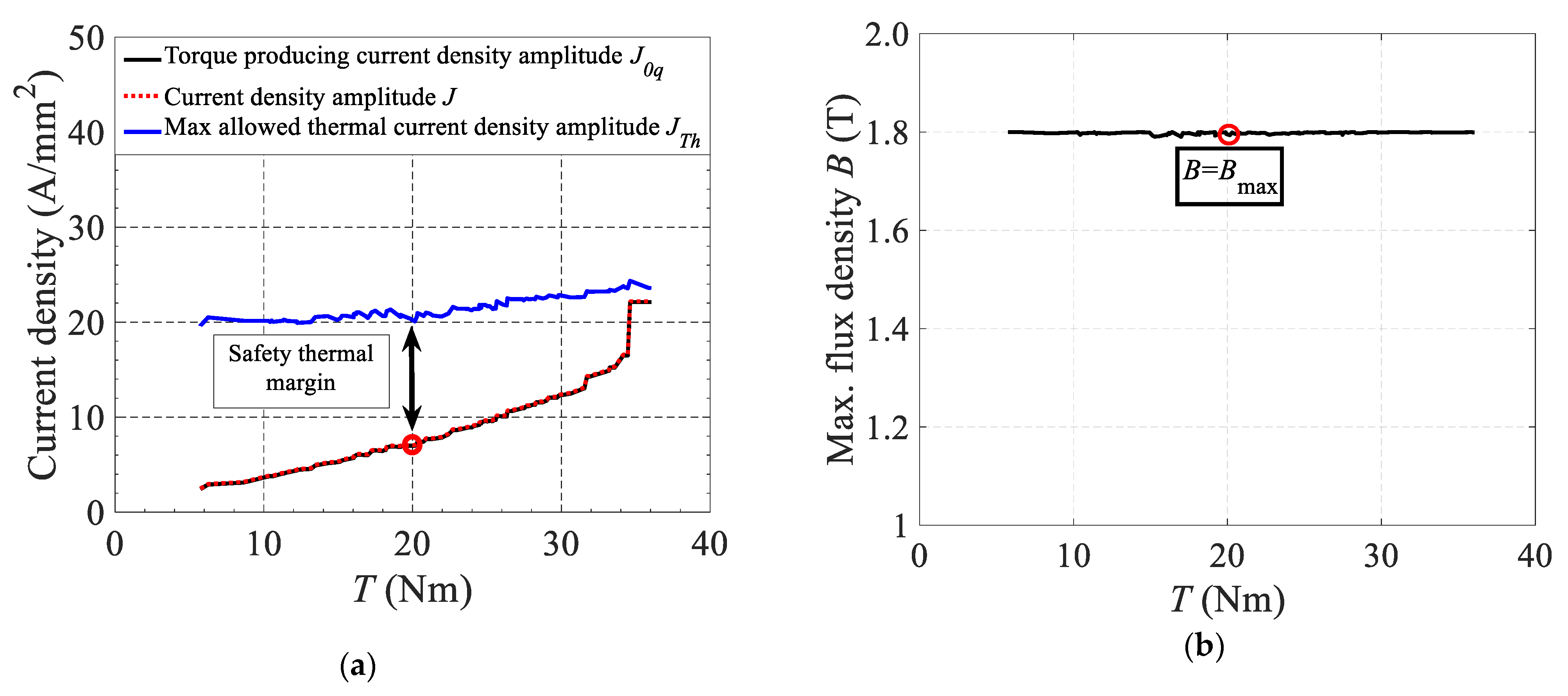
Current density and magnetic flux density. In (a) the torque producing current density , the current density, J, and the maximum allowed thermal current density, , as a function of the torque, T, and in (b) the maximum value of flux density, B, as a function of the torque, T.
Figure 13.
Current density and magnetic flux density. In (a) the torque producing current density , the current density, J, and the maximum allowed thermal current density, , as a function of the torque, T, and in (b) the maximum value of flux density, B, as a function of the torque, T.
Figure 14.
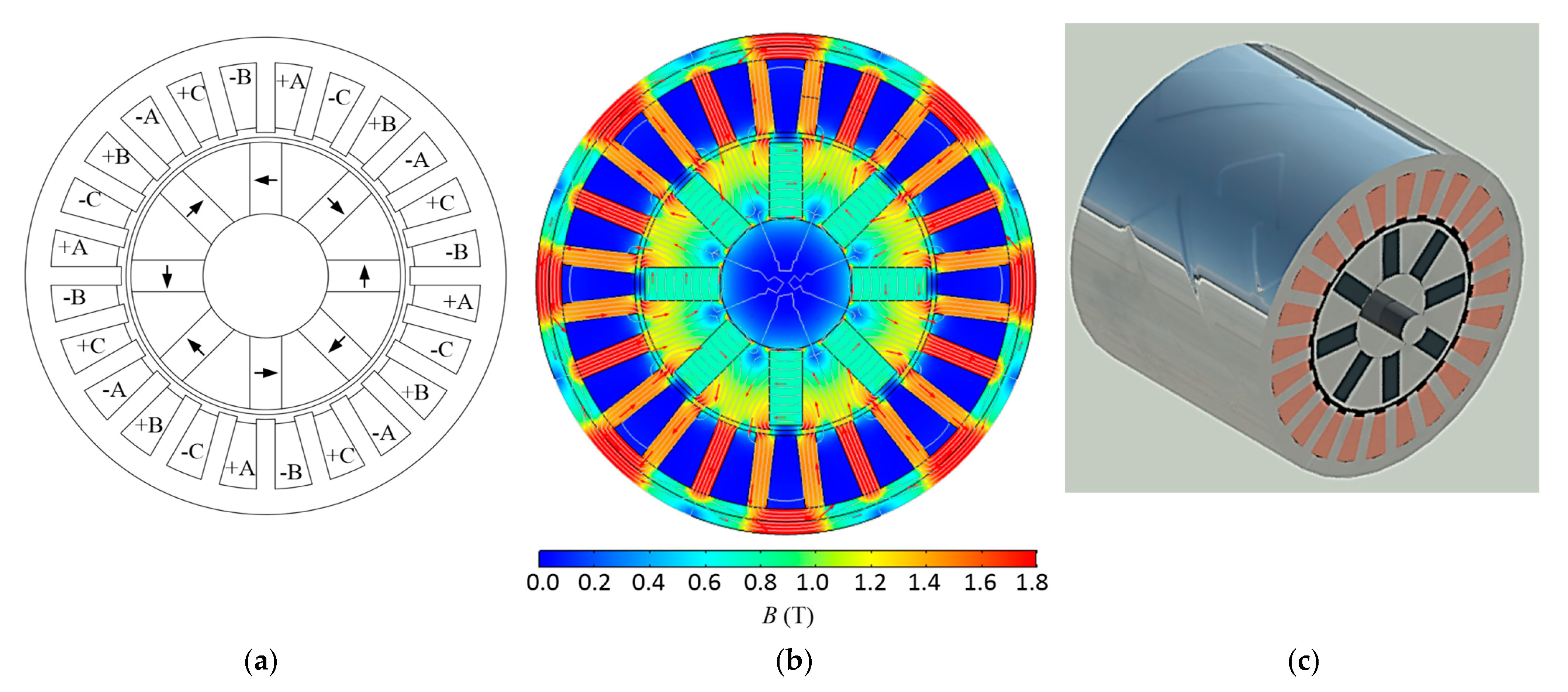
Optimized solution for 20 Nm: (a) geometry, (b) distribution of magnetic flux density, and (c) 3D geometry.
Figure 14.
Optimized solution for 20 Nm: (a) geometry, (b) distribution of magnetic flux density, and (c) 3D geometry.
Figure 15.
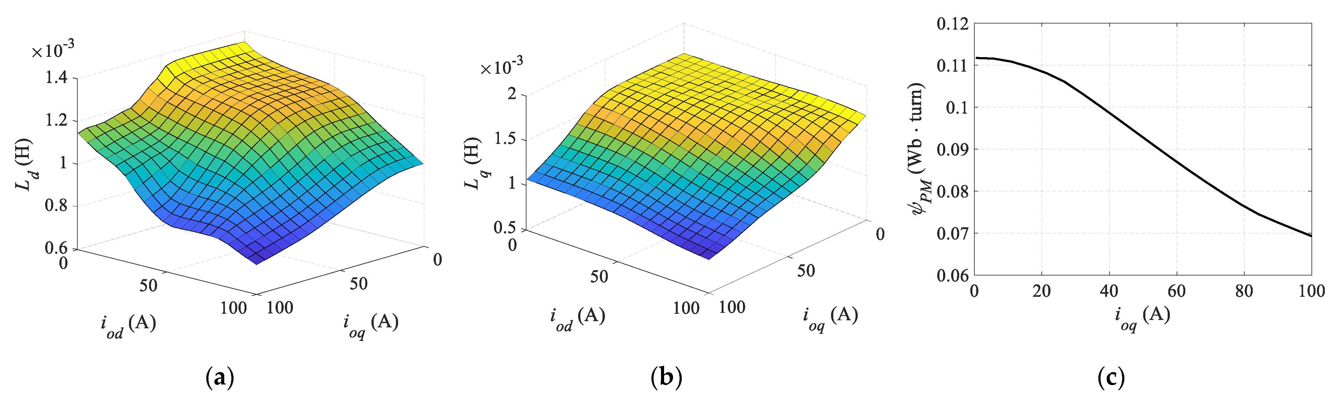
Optimized solution’s induction coefficients (a) , (b) , and (c) permanent magnet linked flux .
Figure 15.
Optimized solution’s induction coefficients (a) , (b) , and (c) permanent magnet linked flux .
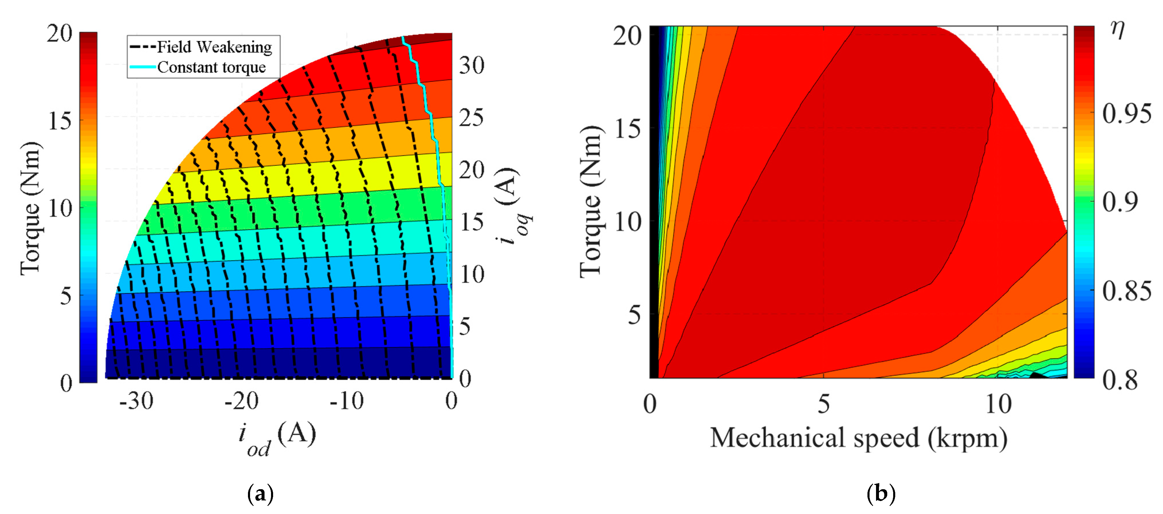
Figure 16.
Optimized solution’s performance: (a) torque map and (b) efficiency map.
Figure 16.
Optimized solution’s performance: (a) torque map and (b) efficiency map.
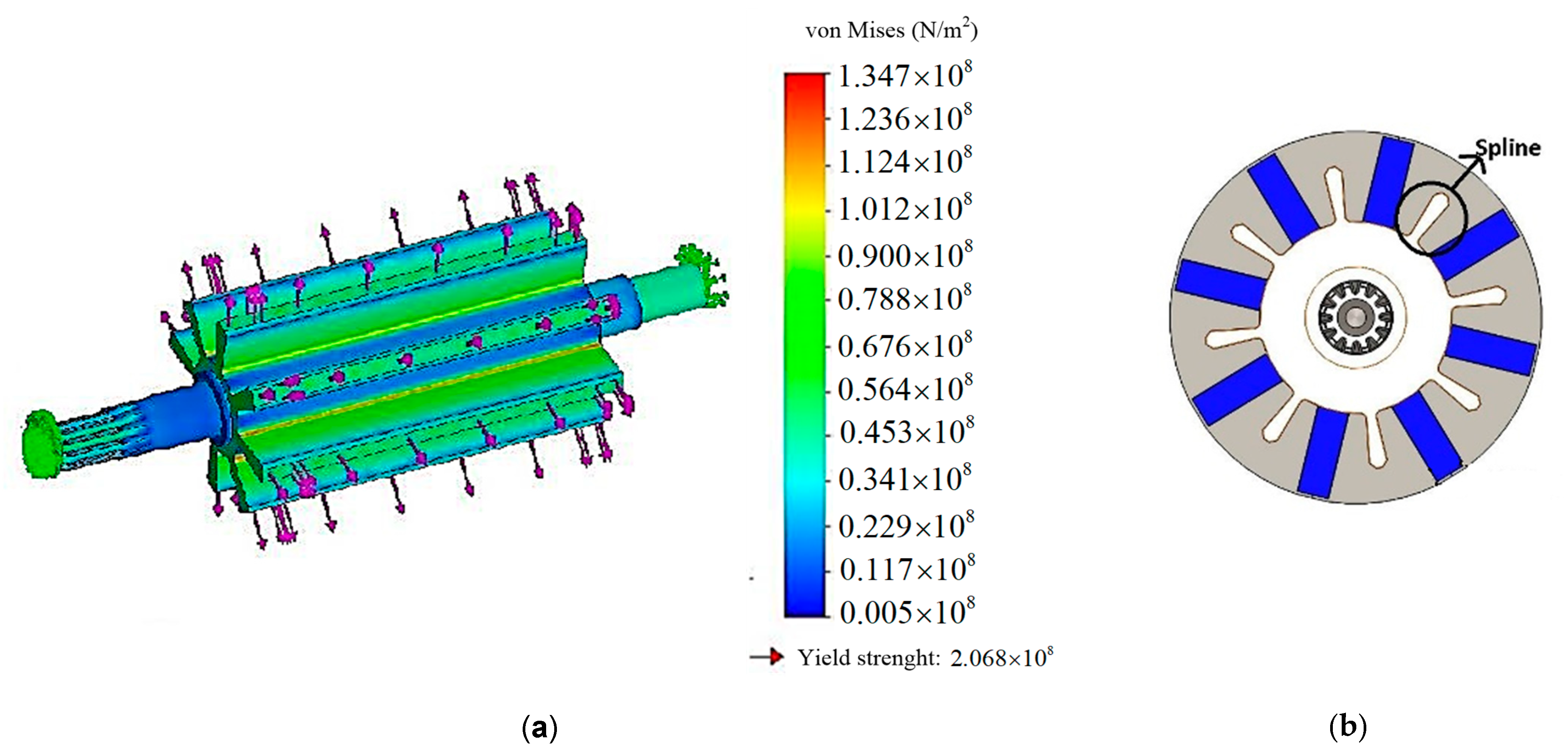
Figure 17.
Shaft and rotor designs: (a) final shaft design and (b) ultimate rotor’s magnetic circuit.
Figure 17.
Shaft and rotor designs: (a) final shaft design and (b) ultimate rotor’s magnetic circuit.
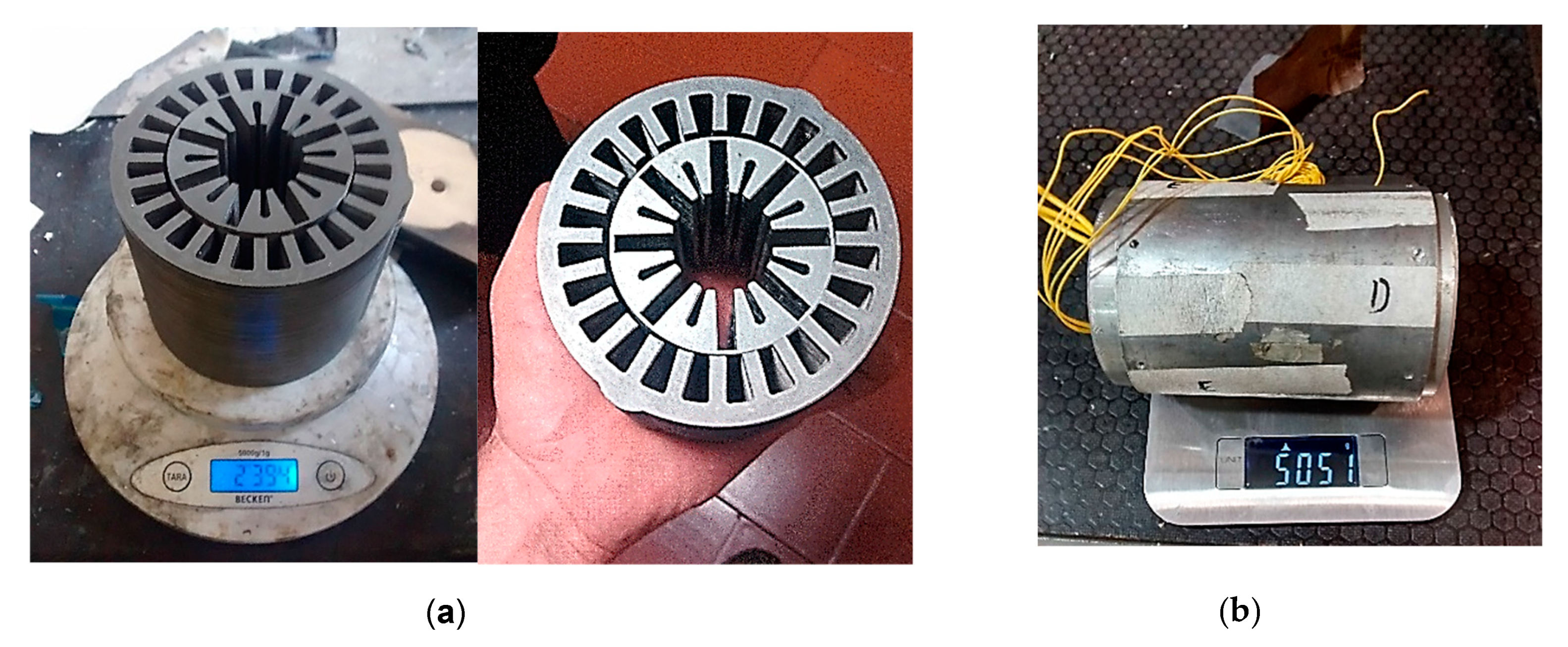
Figure 18.
Final motor prototype: (a) magnetic circuit, (b) assembled prototype.
Figure 18.
Final motor prototype: (a) magnetic circuit, (b) assembled prototype.
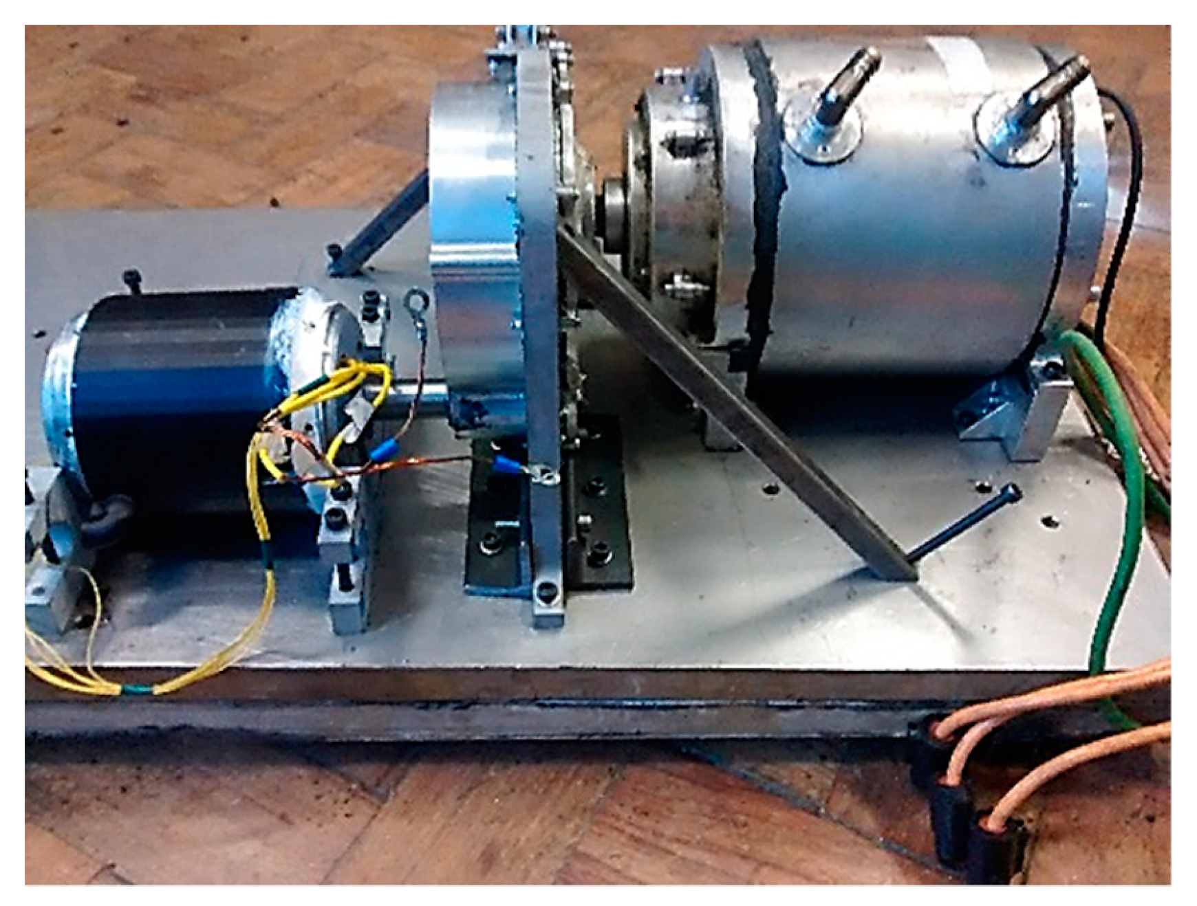
Figure 19.
Test bench configuration with the prototype (left side) and Siemens motor (right side) mechanically coupled through a transmission gear.
Figure 19.
Test bench configuration with the prototype (left side) and Siemens motor (right side) mechanically coupled through a transmission gear.
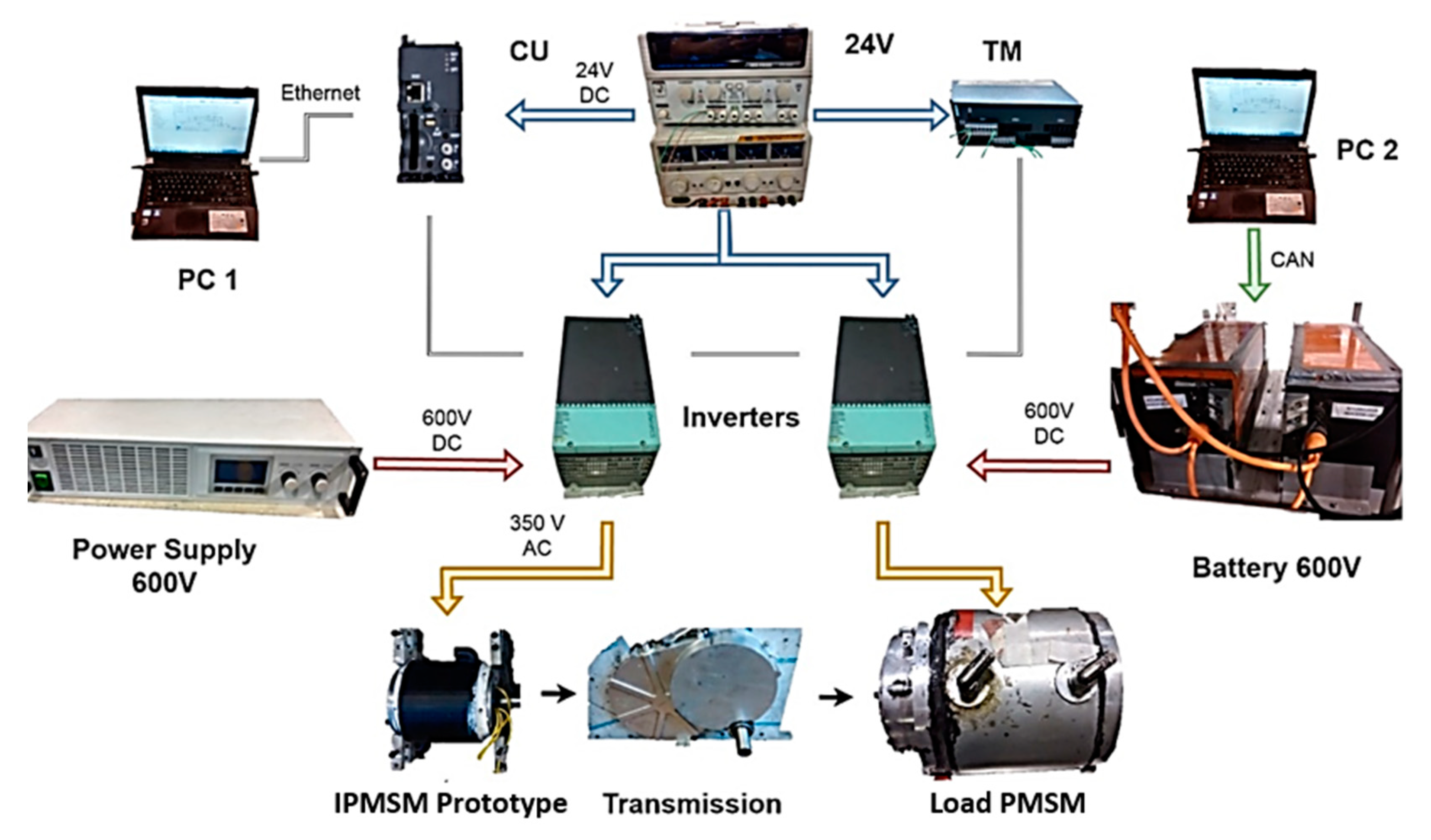
Figure 20.
Overall diagram of the working testbench.
Figure 20.
Overall diagram of the working testbench.
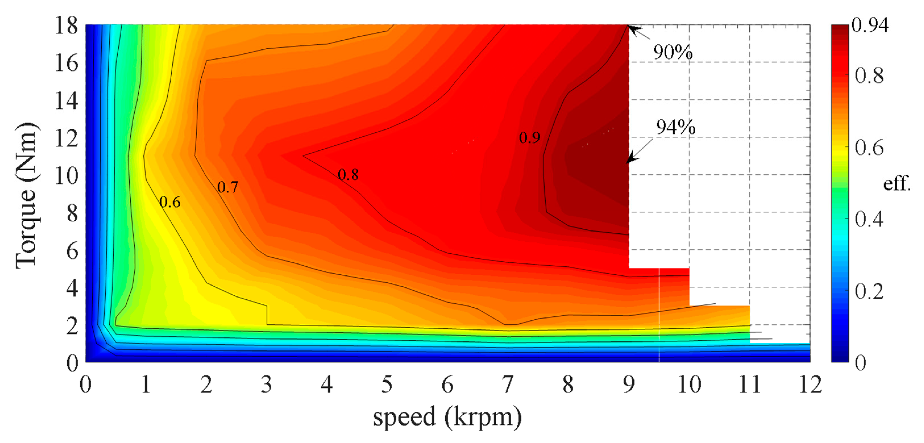
Figure 21.
Experimentally estimated efficiency map.
Figure 21.
Experimentally estimated efficiency map.
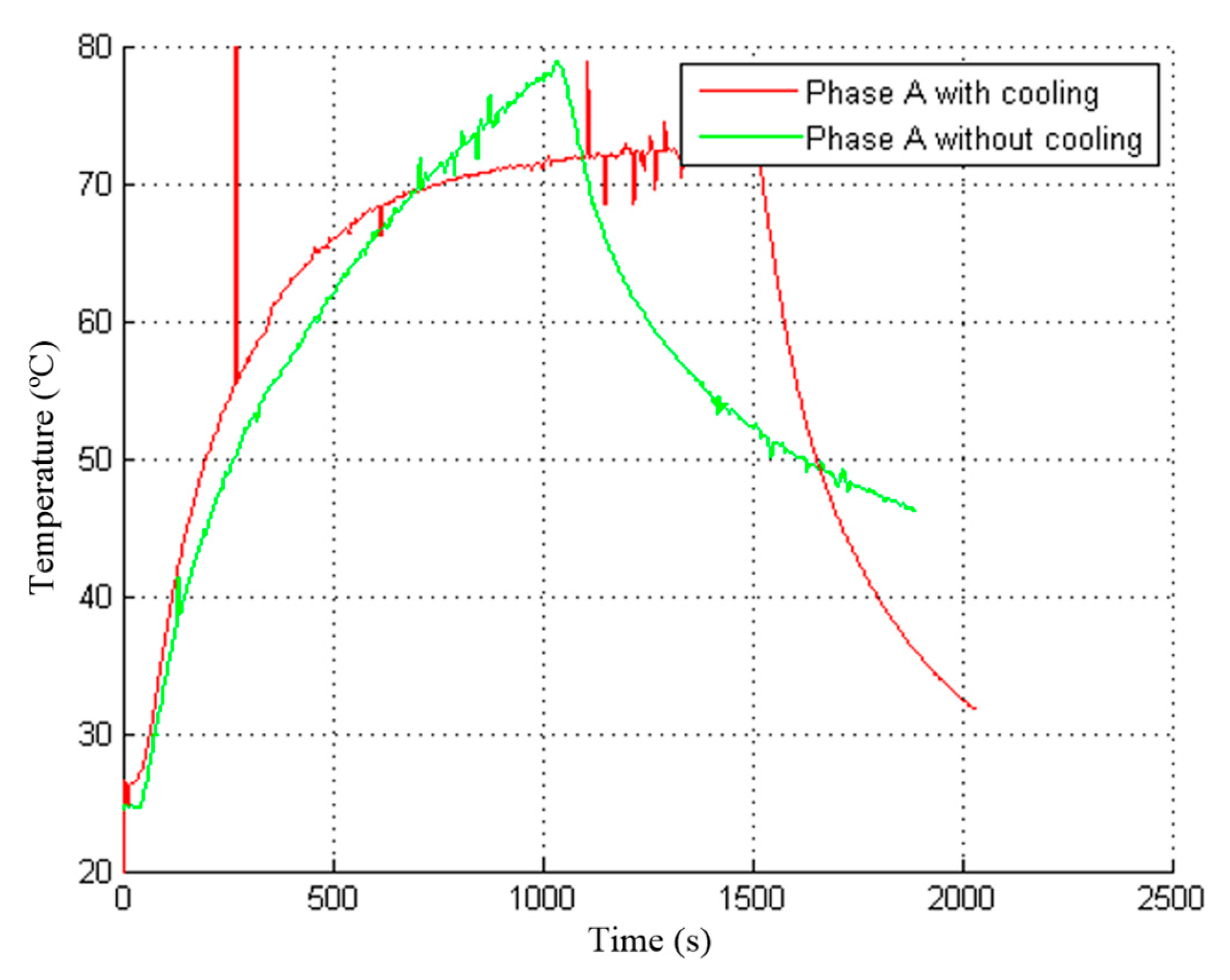
Figure 22.
Experimental temperature with the nominal current.
Figure 22.
Experimental temperature with the nominal current.
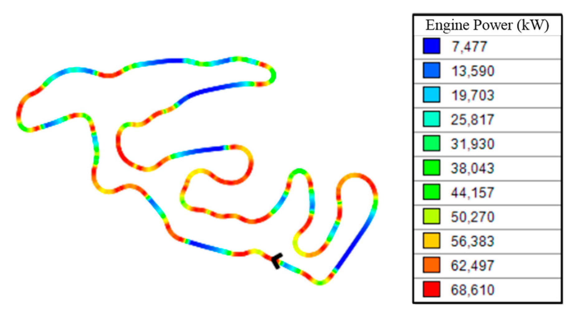
Figure 23.
Optimal power developed along the FSAE autocross Germany track for the characteristics of the prototyped motor.
Figure 23.
Optimal power developed along the FSAE autocross Germany track for the characteristics of the prototyped motor.
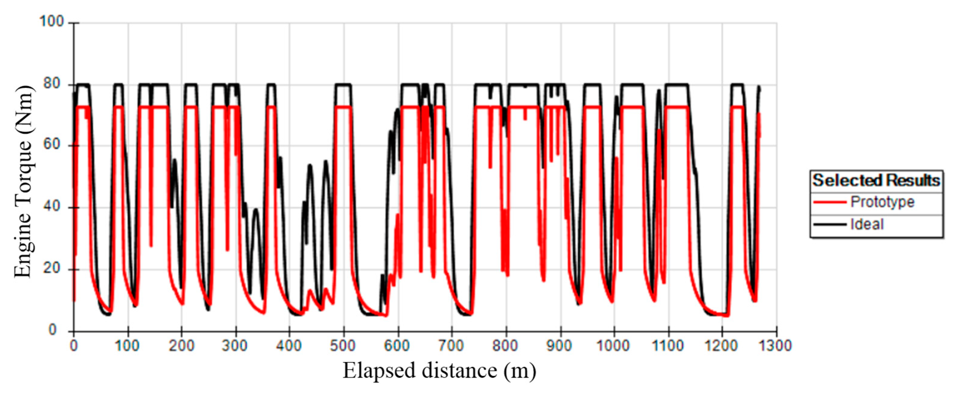
Figure 24.
Optimal torque developed along the FSAE Autocross Germany track for the characteristics of the ideal optimized motor and the prototyped motor.
Figure 24.
Optimal torque developed along the FSAE Autocross Germany track for the characteristics of the ideal optimized motor and the prototyped motor.
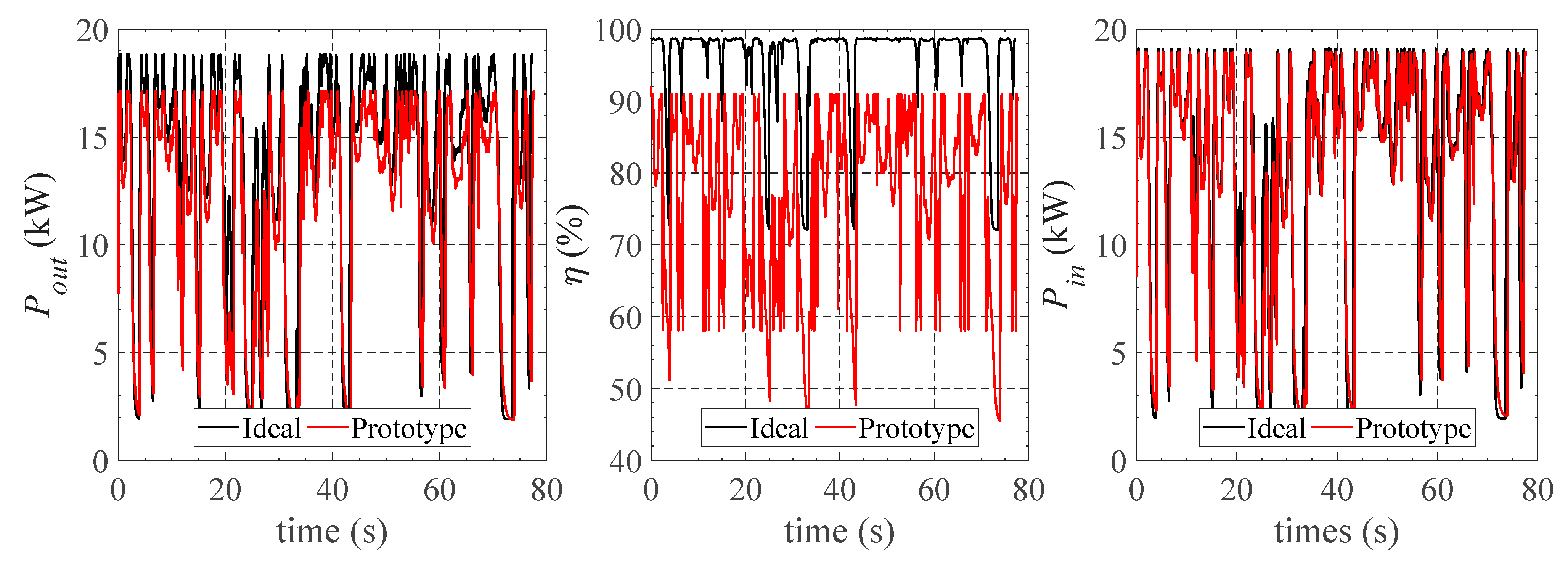
Figure 25.
Motor output power, Pout, efficiency, η, and input power, Pin, along the FSAE Autocross Germany track for the ideal optimized motor and the prototyped motor.
Figure 25.
Motor output power, Pout, efficiency, η, and input power, Pin, along the FSAE Autocross Germany track for the ideal optimized motor and the prototyped motor.
Table 1.
Requirements for each internal permanent magnet synchronous machine (IPMSM).
Table 1.
Requirements for each internal permanent magnet synchronous machine (IPMSM).
| Requirement | Value |
|---|
| Nominal power | 20 kW |
| Maximum torque | 20 Nm |
| Rated speed | 8000 rpm |
| Maximum speed | 12,000 rpm |
| Maximum voltage * | 380 V |
| Peak current * | 100 A |
Table 2.
Mechanical properties of NGO 35JN200 electrical steel.
Table 2.
Mechanical properties of NGO 35JN200 electrical steel.
| Property | NGO 35JN200 |
|---|
| Ultimate Tensile Strength | 450 MPa |
| Density | 7.65 g/cm3 |
Table 3.
Properties of stainless steel ASI 316.
Table 3.
Properties of stainless steel ASI 316.
| Property | Stainless Steel
ASI 316 |
|---|
| Density | 8.00 g/cm3 |
| Yield tensile strength | 290 MPa |
| Electrical resistivity | 75 μΩ.cm |
| Thermal conductivity | 16.2 W/(m.K) |
| Magnetic relative permeability | 1.0008 |
Table 4.
Properties of N40H grade neodymium-iron-boron (NdFeB) permanent magnet material.
Table 4.
Properties of N40H grade neodymium-iron-boron (NdFeB) permanent magnet material.
| Property | NdFeB N40H |
|---|
| Residual magnetic flux density | 1.36 ± 0.03 T at 20 °C |
| Coercivity | 1051 ± 56 kA/m |
| Energy product | 357 ± 16 kJ/m3 |
| Max. operating temperature | 120 °C |
| Curie temperature | 320 °C |
Table 5.
Motor winding layout analysis results.
Table 5.
Motor winding layout analysis results.
| Study | Airgap mmf/ampere Fundamental Component | Airgap mmf/ampere Sum of Harmonics | Balanced Condition |
|---|
| 12 slots/6 poles | 0.574 | 1.790 | Yes |
| 12 slots/8 poles | 0.414 | 1.169 | Yes |
| 12 slots/10 poles | 0.369 | 2.137 | No |
| 24 slots/6 poles | 0.979 | 2.512 | Yes |
| 24 slots/8 poles | 0.956 | 0.414 | Yes |
| 24 slots/10 poles | 0.732 | 2.394 | Yes |
| 30 slots/6 poles | 1.501 | 2.630 | No |
| 30 slots/8 poles | 0.88 | 3.576 | No |
| 30 slots/10 poles | 0.902 | 2.097 | No |
Table 6.
Optimization decision variables.
Table 6.
Optimization decision variables.
| Variable | Description | Range |
|---|
| Rotor radius | 20–40 mm |
| Stator outer ring width | 1–20 mm |
| Magnet width | 1–7 mm |
| Magnet length | 5–15 mm |
| Teeth width | 1–10 mm |
| Teeth length | 7–20 mm |
| Airgap size | 1–5 mm |
| Shaft radius | 5–30 mm |
| Torque producing current density (q axis) | 1–60 A/mm2 |
Table 7.
Optimization constraints by type and respective ranges.
Table 7.
Optimization constraints by type and respective ranges.
| Constraint Type | Constraint | Range |
|---|
| Geometrical | Weight | <5 kg |
| Stator outer radius | <50 mm |
| Motor stack length | =80 mm |
| Thermal | PM’s maximum temperature | <120 °C |
| Windings temperature | <180 °C |
| Magnetic | Magnetic flux density | <1.6T + 10% |
Table 8.
Optimization decision variables.
Table 8.
Optimization decision variables.
| Variable | Description | Optimized Solutions |
|---|
| Rotor radius | 29.0 mm |
| Stator outer ring width | 5.3 mm |
| Magnet width | 6.6 mm |
| Magnet length | 15.0 mm |
| Teeth width | 3.9 mm |
| Teeth length | 14.6 mm |
| Airgap size | 1.0 mm |
| Shaft radius | 13 mm |
| Torque producing current density (q-axis) | 6.99 A/mm2 |
Table 9.
Torque, speed, and efficiency map of the developed prototype.
Table 9.
Torque, speed, and efficiency map of the developed prototype.
| Torque (Nm) | Speed (krpm) |
|---|
| 0.5 | 1 | 2 | 3 | 4 | 5 | 6 | 7 | 8 | 9 | 10 | 11 | 12 |
|---|
| 1.8 | 0.52 | 0.55 | 0.57 | 0.60 | 0.61 | 0.63 | 0.66 | 0.70 | 0.68 | 0.67 | 0.65 | 0.6 | 0.58 |
| 3.6 | 0.46 | 0.54 | 0.59 | 0.60 | 0.65 | 0.67 | 0.71 | 0.72 | 0.73 | 0.75 | 0.73 | 0.72 | - |
| 5.5 | 0.44 | 0.53 | 0.62 | 0.70 | 0.73 | 0.76 | 0.80 | 0.81 | 0.82 | 0.85 | 0.86 | - | - |
| 7.3 | 0.43 | 0.56 | 0.65 | 0.75 | 0.76 | 0.80 | 0.82 | 0.88 | 0.91 | 0.92 | - | - | - |
| 10.9 | 0.42 | 0.62 | 0.72 | 0.79 | 0.81 | 0.83 | 0.84 | 0.86 | 0.93 | 0.94 | - | - | - |
| 14.5 | 0.42 | 0.52 | 0.73 | 0.73 | 0.74 | 0.76 | 0.80 | 0.85 | 0.90 | 0.92 | - | - | - |
| 18.2 | 0.37 | 0.52 | 0.66 | 0.68 | 0.68 | 0.69 | 0.75 | 0.80 | 0.85 | 0.90 | - | - | - |


