Article

Fault Analysis and Design of a Protection System for a Mesh Power System with a Co-Axial HTS Power Cable

1
Department of Electrical Engineering, Incheon National University, Songdo-dong, 119 Academy-ro, Yeonsu-gu, Incheon 22012, Korea
2
KEPCO Research Institute, Daejeon 34056, Korea
*
Author to whom correspondence should be addressed.
Energies 2020, 13(1), 220; https://doi.org/10.3390/en13010220
Submission received: 13 December 2019 / Revised: 27 December 2019 / Accepted: 28 December 2019 / Published: 2 January 2020
(This article belongs to the Special Issue Electric Power Systems Research 2019)

Abstract

:
The uses of high-temperature superconducting (HTS) cables pose a challenge of power system protection since the impedance of the HTS cable is varied during fault conditions. The protection systems should be designed properly to ensure the reliability and stability of the whole system. This paper presents a fault analysis of the co-axial HTS cable in the mesh system and proposes a coordinated protection system. In the proposed protection system, the main protection is the differential current relay whereas the backup protections are the overcurrent and directional overcurrent relays. The normal and abnormal relay operations are considered to analyze the transient fault current in the HTS cable and evaluate the performance of the proposed coordinated protection system. Characteristics of cable impedances and temperatures under various fault conditions are presented. The proposed protection scheme is validated by the simulation in the PSCAD/EMTDC program. Simulation results show that the coordinated protection scheme could successfully protect the HTS cables in both normal and abnormal relay operations.

1. Introduction

High-temperature superconductors (HTS) exhibit superconducting behavior at critical temperature that is varied according to the layered materials. Magnesium diboride (MgB2) is generally regarded as a conventional HTS with its critical temperature of 39 K. Cuprate superconductors such as YBCO and BSCCO with transition temperatures above the 77 K boiling point of liquid nitrogen have been found [1]. Iron-based superconductors are considered the second class of HTS with a critical temperature in excess of 100 K [2]. High-temperature superconductors have become suitable for practical uses and have great potential for wide-ranging technological applications, such as HTS cables.
HTS cables are able to conduct bulk power at low voltage cables, which results in the widespread application in electric power systems [3,4,5]. The uses of HTS cables in HVDC transmission systems have been presented in [6,7,8]. In urban areas where land availability is limited, the HTS cable can replace the traditional high voltage transmission system to supply power for the urban load [9,10,11]. Since the applications of HTS cables in power systems have been increased significantly, fault analysis and designing the protection system of HTS cables are essential to ensure the stability and reliability of power systems.
In order for designing a protection system, fault analysis of the HTS cable has been presented in several studies. The fault analysis of a 110 kV HTS power cable presented in [12] showed that the fault current could be beyond the critical current in case of an insulation breakdown fault. The transient analysis of the DC HTS power cable in the HVDC system was investigated in [13]. Since the converter controller of the HVDC system could play the role of current limiter, the DC HTS cable could operate normally without the quenching phenomenon. The transient current analysis of a 66 kV HTS cable in [14] indicated that the uses of copper shield layers could protect the HTS tape layer from burning out. The real-time simulation of the HTS power cable was carried out in [15] to analyze the fault current characteristic, in which the real miniaturized HTS power cable is incorporated into the 22.9 kV utility power system. Fault analysis has shown that the impedance of the HTS cables could be varied significantly during transient, which causes a negative impact on the protection system.
The impacts of HTS cables on power system protection have been studied in [16]. It was shown that the change of cable impedance during a fault has a negative impact on the distance relay. In addition, the setting of the overcurrent relay in the traditional power system should be revised due to a very high fault current. An improved protective relay system was proposed in [17], in which the decision-making algorithm was proposed to improve the performance of differential current relay. In [18], the real-time protection algorithm of a HTS power cable was proposed. Depending on the cable property and geometry, the zero sequence component of transient current exists when the quench occurs in the HTS cable. Thus, based on the vector analysis of fault current by the symmetrical coordinate method, the real-time protection system is designed to protect the HTS power cable. The action criterion protection was proposed in [19], in which the electrical and non-electrical signals were used to detect the quench fault of the HTS cable. An optimal protection scheme of HTS power cable and fault current limiter was proposed in [20] to deal with the change of system configuration.
Various studies have analyzed the fault current characteristic and proposed the protection system of the HTS power cable in the utility power system. However, existing studies only deal with the uses of HTS cables in the radial feeder system where the protection system could be simply designed by the differential current and overcurrent relays. In case the HTS power cable is used in the mesh system, the bidirectional power flow through the HTS cable leads to the complex design of the protection system. In order to address the problem, this study deals with the application of the HTS cable into the mesh power system. The main contributions of this study are as follows:
Propose coordinated protection of the HTS cables in the mesh power system. In the proposed coordination protection of the HTS cables, the main protection is the differential current relay while the backup protections are the overcurrent (OCR) and directional overcurrent relays (DOCRs). Coordination between OCR and DOCR is proposed to protect the HTS cables.
Analyze the transient characteristic of HTS cables under normal and abnormal relay operations. The transient current, cable resistances, and temperatures under fault conditions are evaluated.
The rest of this paper is organized as follows. Section 2 presents the modeling of the HTS power cable in the mesh system. The proposed coordinated protection scheme is described in Section 3. Simulation results are shown in Section 4 and the conclusion of this paper is provided in Section 5.

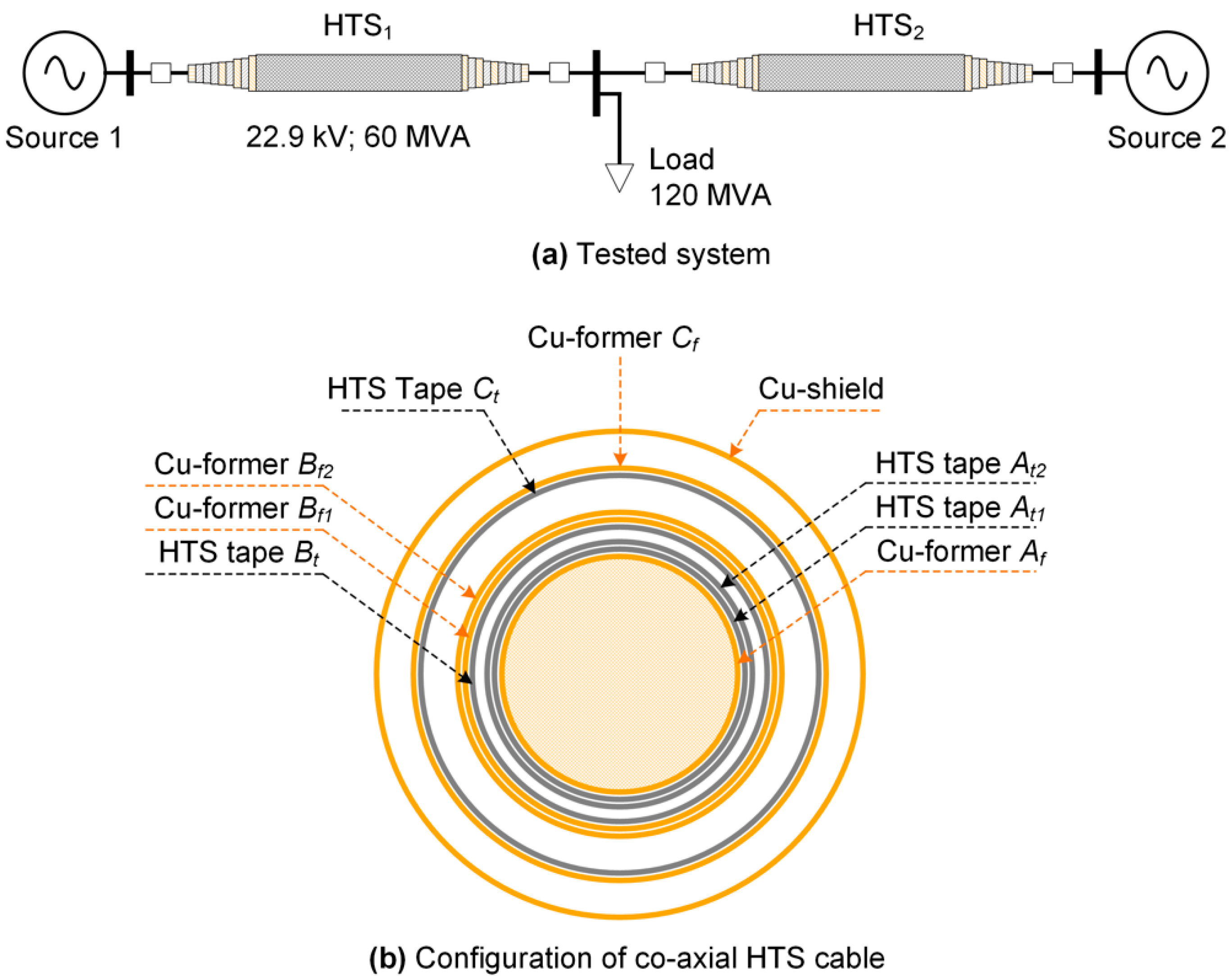
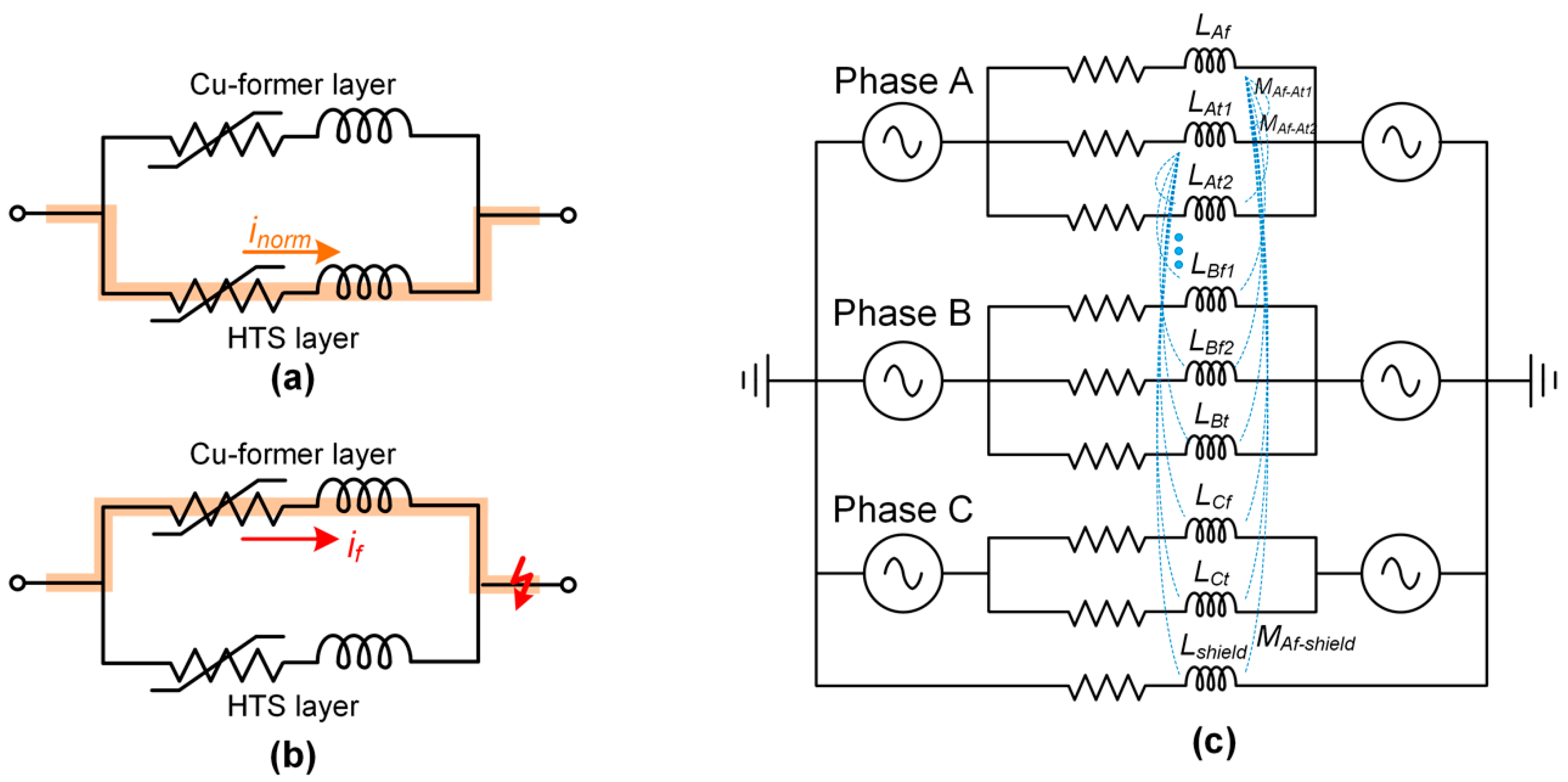
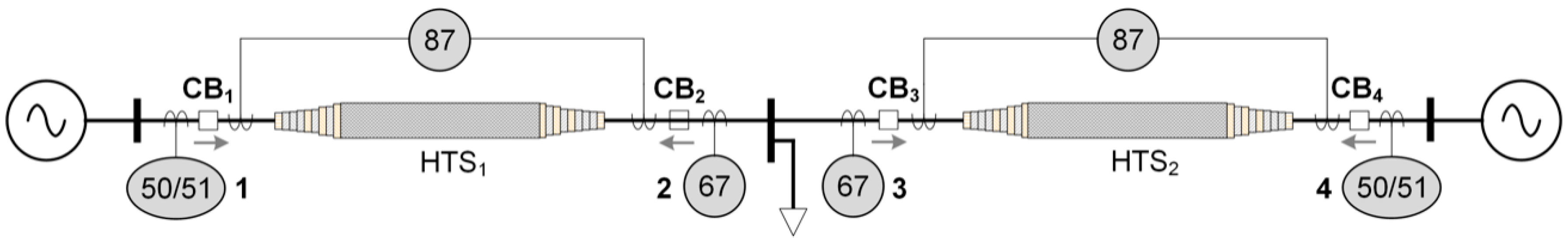
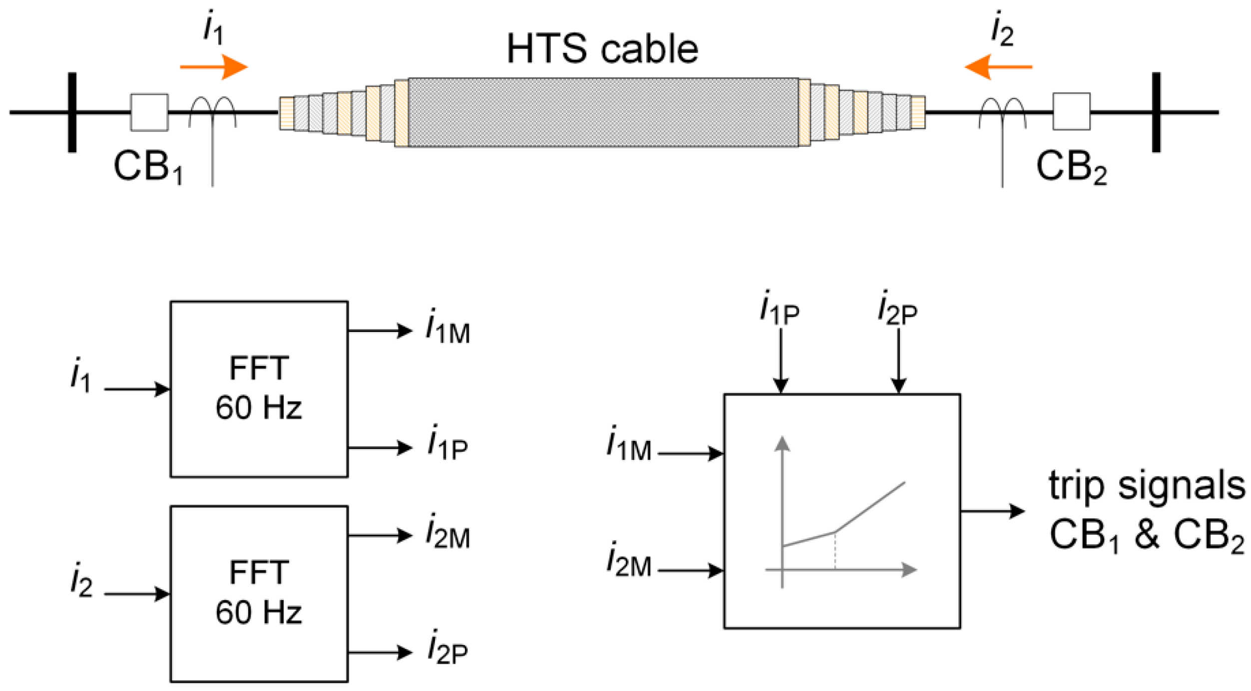
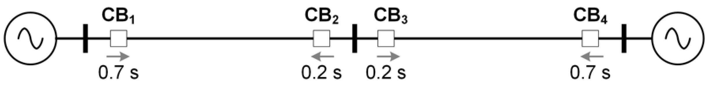
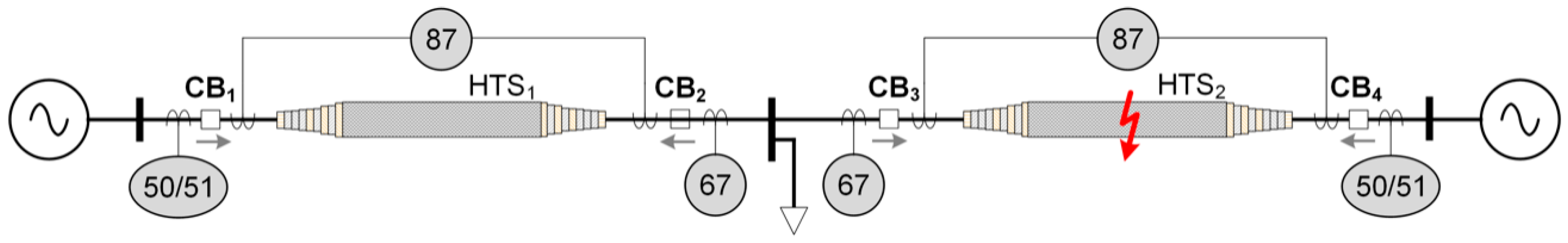
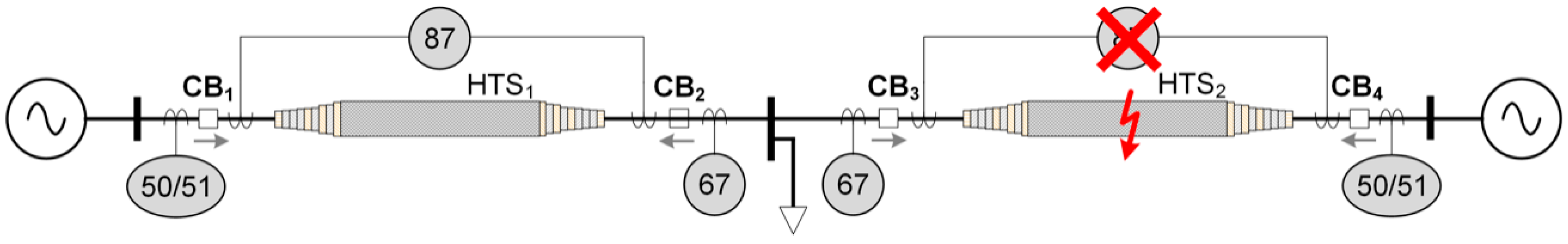
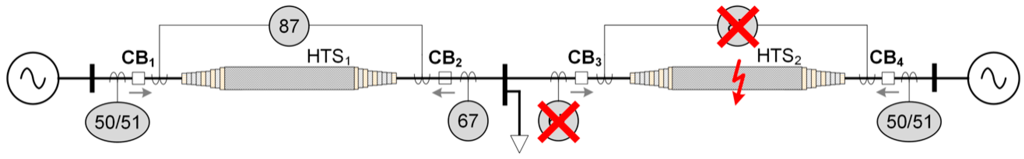
2. System Description

In the case of urban areas where land availability is limited, it is important to establish a bulk capacity underground cable with high reliability. Since the conventional distribution line cable has the limitation of increasing transfer capability, multi-circuit underground cables along with the construction of new substations are essential. However, this solution has a negative impact on the environment and capital cost. With the capability of conducting bulk power transfer at low voltage and low losses, the HTS cable offers an alternative solution to enlarge the transfer capacity of the transmission and distribution networks and reduce the substation facilities in a metropolitan city.
The use of HTS cables causes adverse effects on the coordination protection of the power system due to the variable impedance during a short-circuit, especially in the case of a mesh system. Figure 1 shows a typical mesh system with the use of HTS cables. Two 22.9 kV sources supply powers for local load through two HTS cables. The nominal voltage of the HTS cable is 22.9 kV and its capacity is 60 MVA. It is assumed that the length of each HTS cable is 1 km. The co-axial HTS cable using Cu-formers is used to conduct powers. Since this study is a continuation of the research presented in [21], the simplified HTS cable model for the transient analysis in previous work is adopted in this study for fault analysis and design of the protection system. Figure 2 shows the operation characteristic and the equivalent scheme of the co-axial HTS cable. The resistance/temperature characteristic of the co-axial HTS cable model is developed in the PSCAD/EMTDC program by the custom model with FORTRAN source code. The variable RLC components are used to model the resistances of the HTS cable. A custom model with a transformer section is used to represent the self and mutual inductances of the HTS cable. More explanation of the co-axial HTS cable could be found in [21]. Detailed parameters of the tested system are given in Table 1.

3. Design of Coordinated Protection

Typically, power system components are protected by the main and backup protection. The main protection provides fast and selective clearing of any circuit fault whereas the backup protection is used to isolate the faulty sections in case the main protection fails to function properly. The main and backup protections should be coordinated with sufficient time delay to ensure that the main protection trips first then the backup protection will trip. Figure 3 shows the protection of the HTS cable in the mesh system. The differential current relays (DCR, 87) are used as the main protection of the HTS cables and the overcurrent (OCR, 50/51) and directional overcurrent (DOCR, 67) relays are used for backup protection of HTS cables. The modeling of protective relays in the PSCAD/EMTDC program is based on the master library of the protection section.

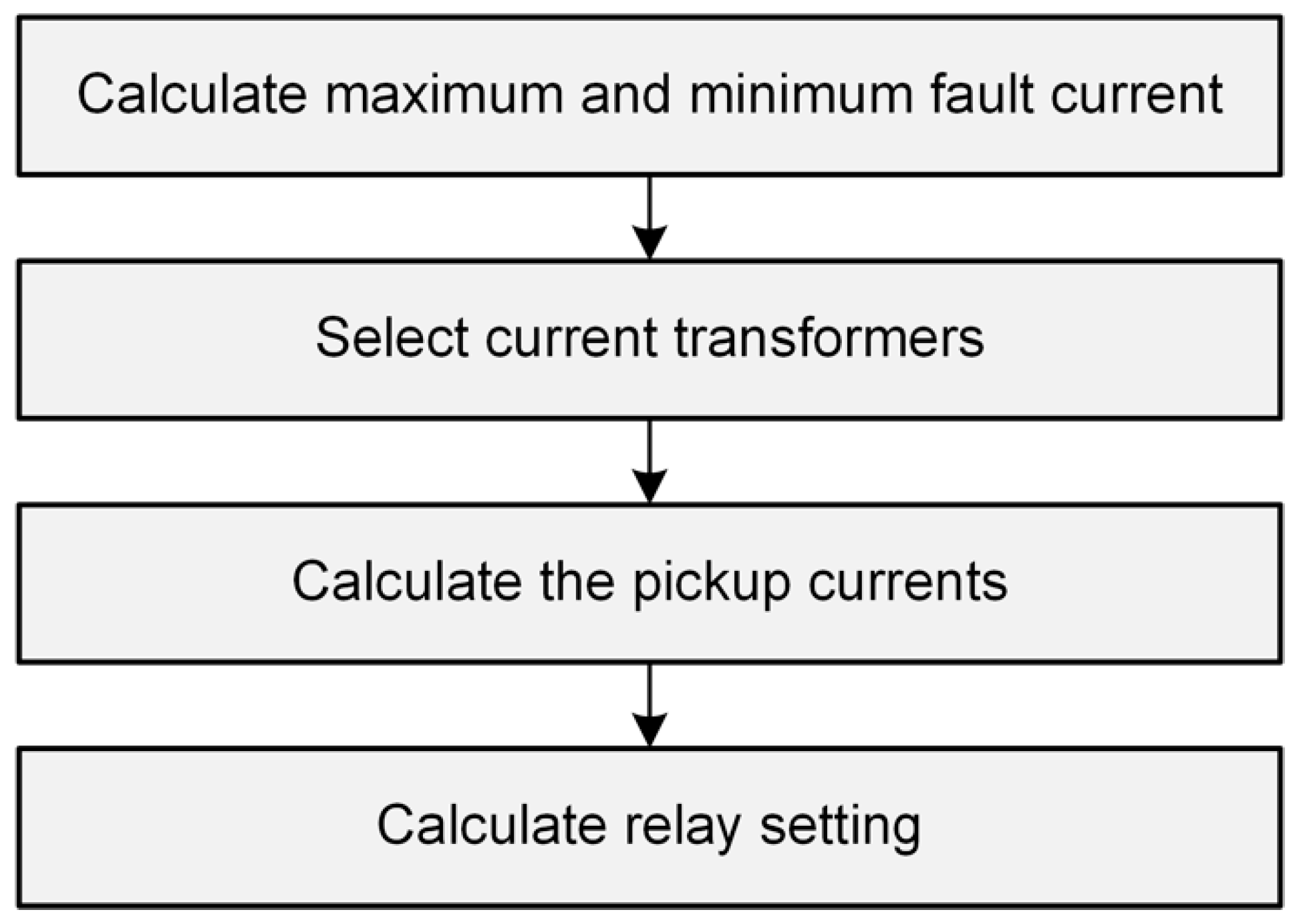
3.1. Procedure for Designing Coordinated Protection

The procedure for designing the coordinated protection system is shown in Figure 4. Firstly, the maximum and minimum fault currents are calculated. Since the impedance of the HTS cable is varied during the fault condition, the fault current is calculated from the detailed HTS cable model in the PSCAD/EMTDC program. Based on the maximum fault current, the parameters of the current transformers are selected accordingly. Then the pickup current of relay and its setting parameter are calculated. The setting parameters of relays are based on the design of coordinated protection of the HTS cable, in which the overcurrent relays play the roles of backup protection for both HTS cables in the tested system.

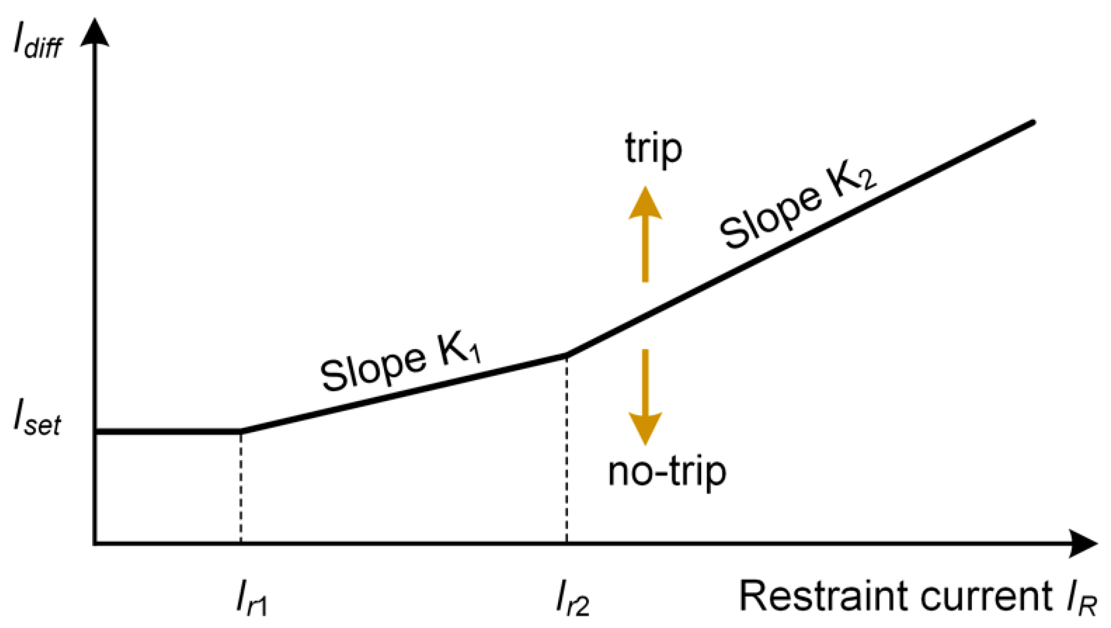
3.2. Design of Differential Current Protection

The main protective relays of HTS cables and transformers are DCR and its characteristic curve is shown in Figure 5. The dual-slope current differential relay module from the master library of the PSCAD/EMTDC program is used in this study. The formulas of differential current threshold ( i d i f f ) and bias current threshold ( i b i a s ) are given by the following forms:
i d i f f = | i 1 + i 2 |
i b i a s = | i 1 | + | i 2 | 2
where i 1 and i 2 are the currents from two sides of the HTS cables or transformers.
Figure 6 shows the implementation of the DCR model in the PSCAD/EMTDC program. The measured currents from CTs are analyzed by Fast Fourier Transformation to obtain the magnitude and phase of the fundamental fault currents. They are then compared to detect the fault in the HTS cables.

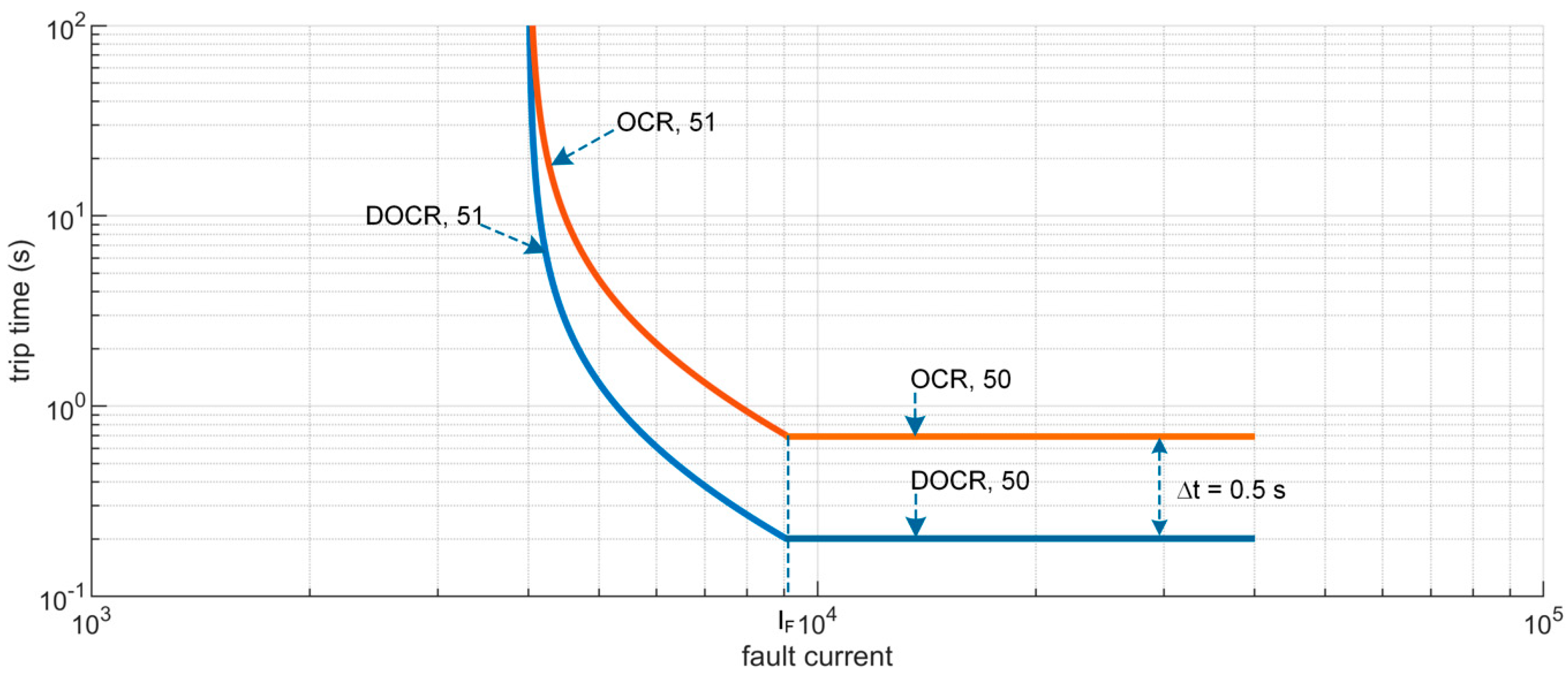
3.3. Design of Time-Graded OCRs

OCRs are used as backup protection for HTS cables. Since two HTS cables are used to conduct powers from two sources, the directional overcurrent relays (DOCRs) are required to detect the current flow in a particular direction in the HTS cables. The DOCRs consist of two elements: a directional element and an OCR. Coordination among OCR and DOCR should be considered to discriminate between faults. In the proposed protection system in Figure 3, relay 1 should coordinate with relay 3 and relay 2 should coordinate with relay 4. The general rule of coordinating two overcurrent relays is to apply the coordination time interval (CTI) in Equation (3) at the short-circuit current or maximum load current.
CTI = t t r i p + Δ t
where t t r i p is the relay trip time and Δ t is the grading time.
In this study, in order to improve the reliability of the protection system, the definite time overcurrent and inverse time overcurrent relays are used in OCRs, in which the pickup current of definite time overcurrent relay is designed based on the short-circuit current and that of inverse time overcurrent relay is selected by 150% of maximum load current. The short-circuit current is calculated by a detailed simulation of the HTS cable system in the PSCAD/EMTDC program. Three-phase-to-ground-fault is applied to the HTS cable system at different locations. Regarding each fault location, the maximum magnitude of the short-circuit current is recorded at different buses, which will be used to calculate the relay setting. The tripping characteristic of inverse time overcurrent relay is given by Equation (4).
t t r i p = T D ( A M p 1 + B )
where T D is the time dial; A ,   B , and p are the trip characteristic constants given in Table 2, which define the OCR characteristics; M = I / I s in which I is the measured current; and I s is the relay setting current.
The design of a coordinated protection system starts with an initial calculation of DOCR (CB3) with the actual tripping time of 0.2 s since it is the backup element of DCR, as shown in Figure 7. The full load current is calculated by
I L = P 3 V = 60 × 10 6 3 × 22.9 × 10 3 = 1512.7   A
Based on the full load current, the ratio of the current transformer is selected as 2000/5 and the pickup current of DOCR is 10 A. The TD value of OCR is calculated as
T D = t t r i p A M p 1 + B = 0.2 39.85 ( 1.5 × 1512.7 × 5 2000 10 ) 1.95 1 + 1.084 = 0.0014
The graded time of DOCR (CB3) and OCR (CB1) is 0.5 s, resulting in the actual tripping time t t r i p of OCR being equal to 0.7 s. Thus, the TD value of OCR is calculated as
T D = t t r i p A M p 1 + B = 0.7 39.85 ( 1.5 × 1512.7 × 5 2000 10 ) 1.95 1 + 1.084 = 0.0049
The coordinated characteristic of OCR and DOCR of the tested system is shown in Figure 8, which includes the characteristics of definite time overcurrent and inverse time overcurrent relays.

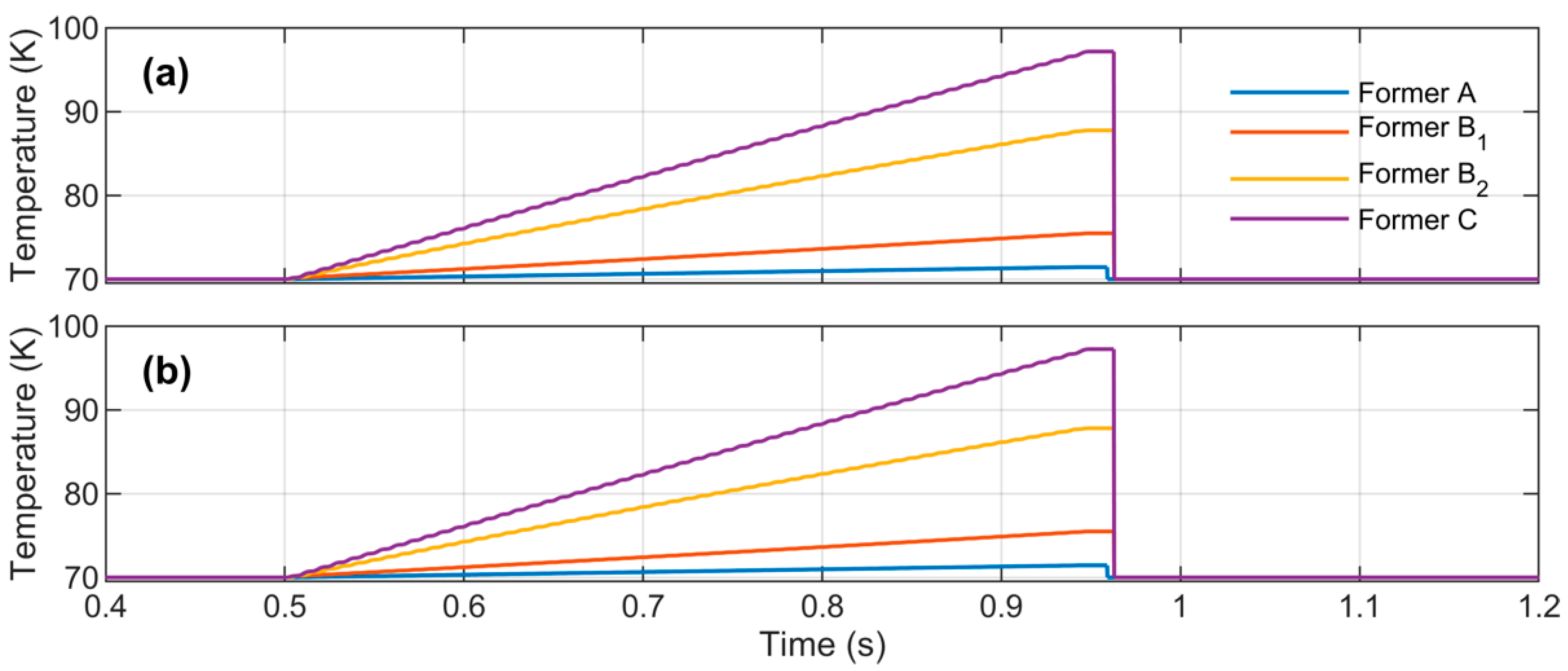
4. Simulation Results

The internal three-phase short-circuit fault in the HTS cable was applied to validate the performance of the proposed protection system. It is assumed that the fault is applied at 0.5 s and the fault resistance is calculated by Warrington’s equation in [22], as given by Equation (8). The mechanism delay of the medium voltage circuit breaker (CB) is five cycles for a complete opening time.
R f = 28707.35 × L I 1.4
where R f is the arc resistance, L is the arc length, and I is the RMS value of fault current.

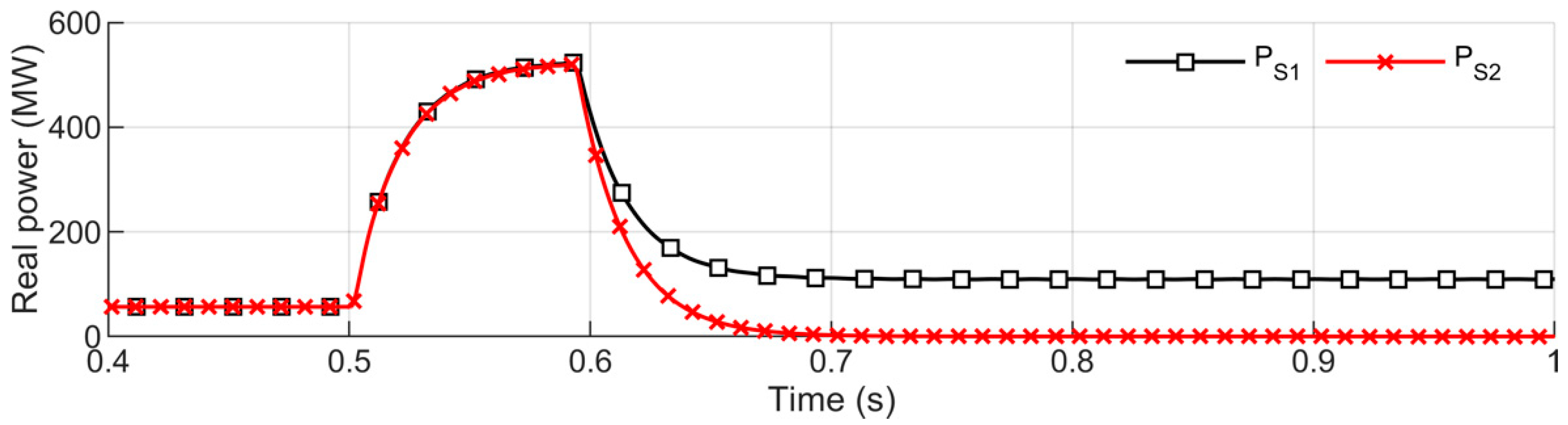
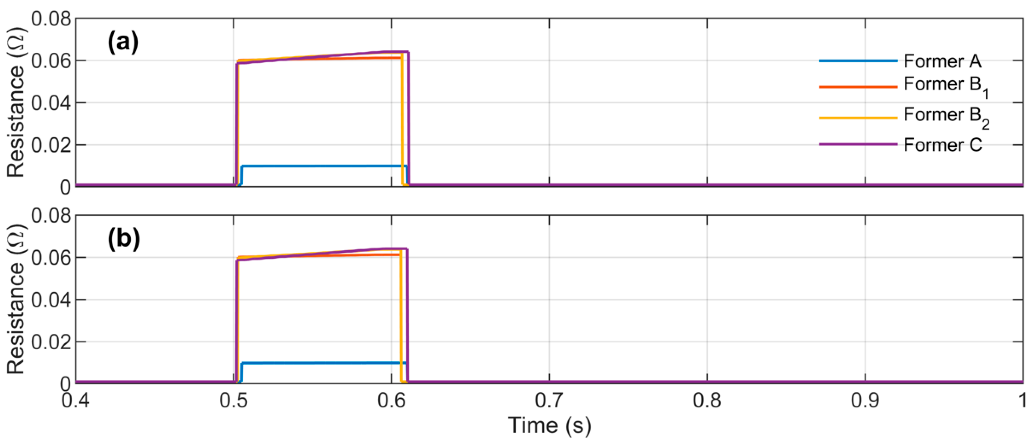
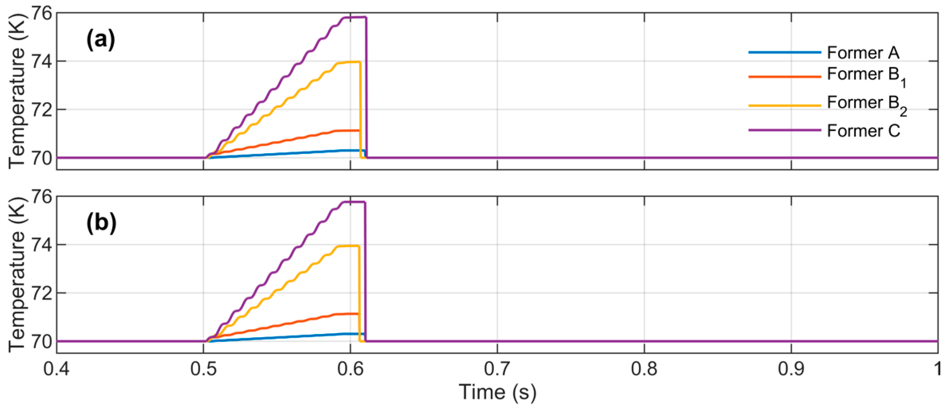
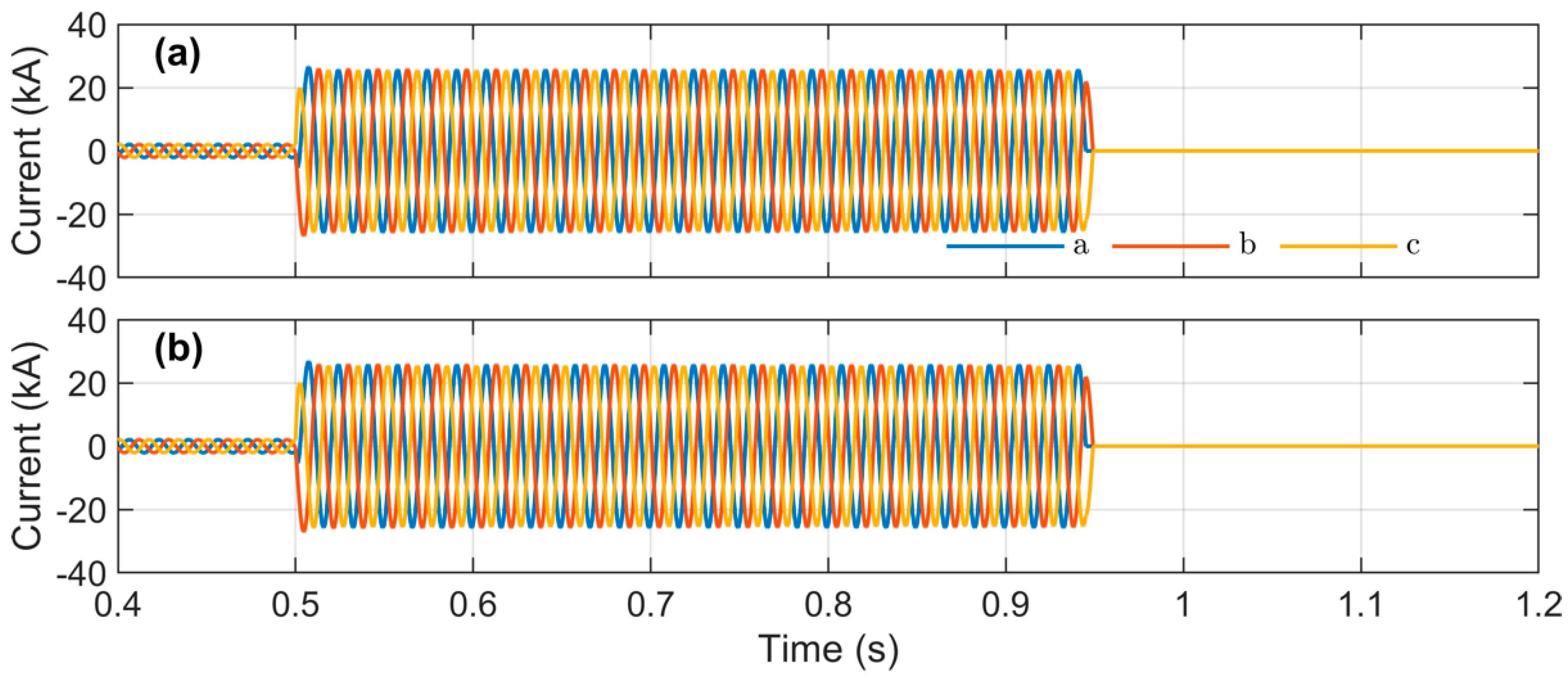
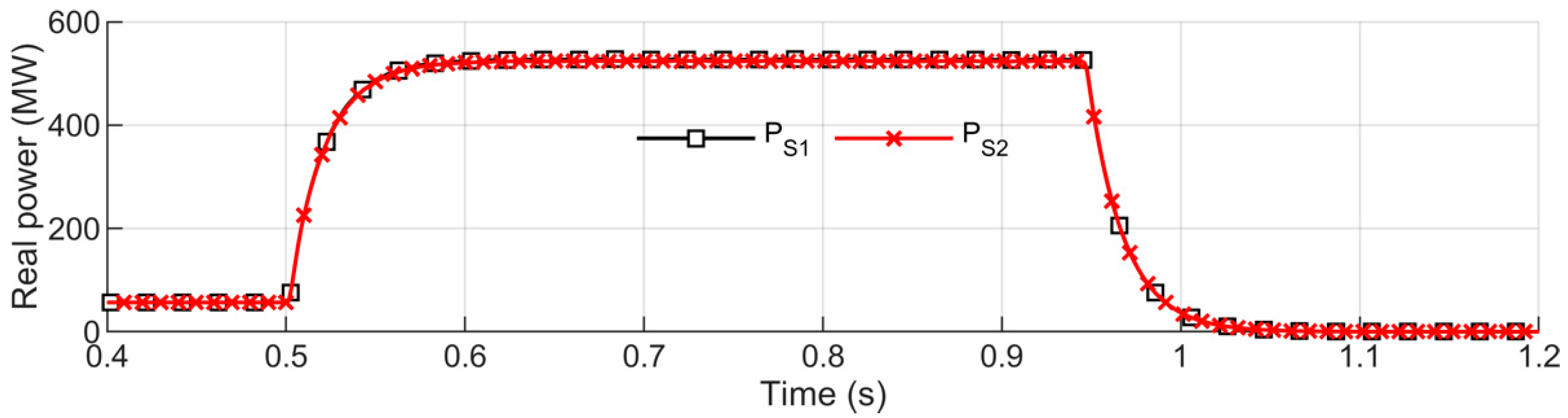
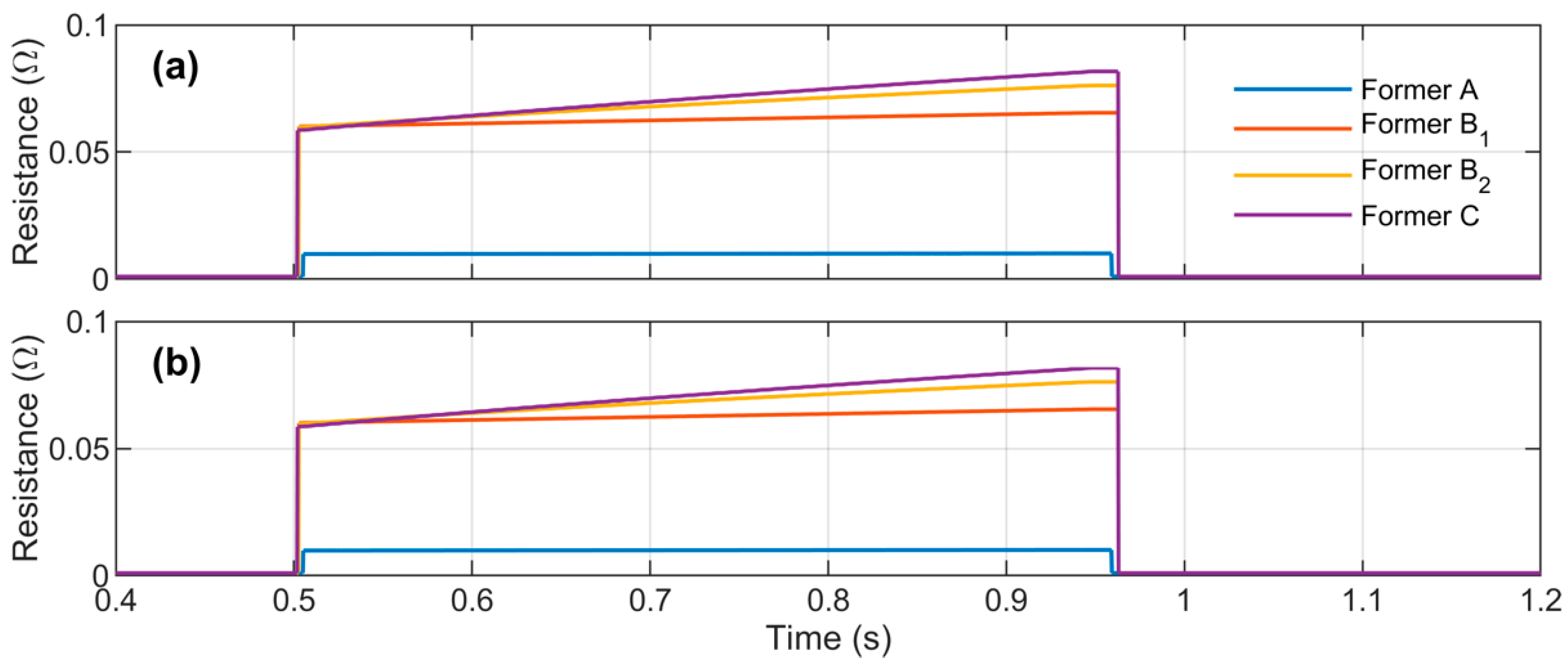
4.1. Case 1: Normal Operation

The tested system shown in Figure 9 is used to verify the proposed coordinated protection system in case of normal relay operation. The internal fault of the HTS2 occurs at 0.5 s. The relay tripping signals of two HTS cables are shown in Figure 10, in which the rising signal indicates that the relay detects the fault and the tripping signal is generated. It can be seen that the fault is detected by the DCR of the HTS2 at 0.508 s. The trip signal from DCR is sent to the CB3 and CB4 to isolate the fault. Figure 11 shows the operation status of circuit breakers, in which the rising signal means the circuit breaker is opened to isolate the fault. It is shown that two CBs are opened completely at 0.592 s. The CB opening time is longer than the detection time due to the CB’s mechanism delay.
The three-phase transient currents through two HTS cables are shown in Figure 12. Initially, two HTS cables conduct an RMS current of 2 kA to supply power for the local load. The fault at 0.5 s causes a rapid increase of HTS2 current from 2 kA to 24.5 kA. The current through the HTS2 is decreased to zero after 0.592 s due to the opening of CB3 and CB4. Meanwhile, the current in HTS2 increases after clearing the fault. Figure 13 shows the power flow into two HTS cables. Initially, two cables conduct the same amount of power. Three-phase-to-ground fault occurs at 0.5 s, resulting in a rapid increase of powers through both HTS cables from 60 MW to 510 MW. After clearing the fault at 0.592 s, the power in HTS2 is reduced to zero while the power in HTS1 is doubly increased compared to the initial condition.
The HTS cable resistances are shown in Figure 14, which illustrates that the cable resistances are increased when the fault occurs. Due to the geometric structure of the HTS cable, the increased resistance of former phase A is smallest whereas it is highest in case of former phase C. The temperatures of the HTS cables shown in Figure 15 indicate that the temperature of former phase C is the highest (~76 K) compared to other phases.
It can be observed that the main protection of the mesh system is operated correctly. Although the current of HTS1 increases significantly, the main and backup protection systems of HTS1 (OCR and DOCR) do not operate in this case since the DCR of HTS2 detected the fault and isolated the HTS2 from the power system.

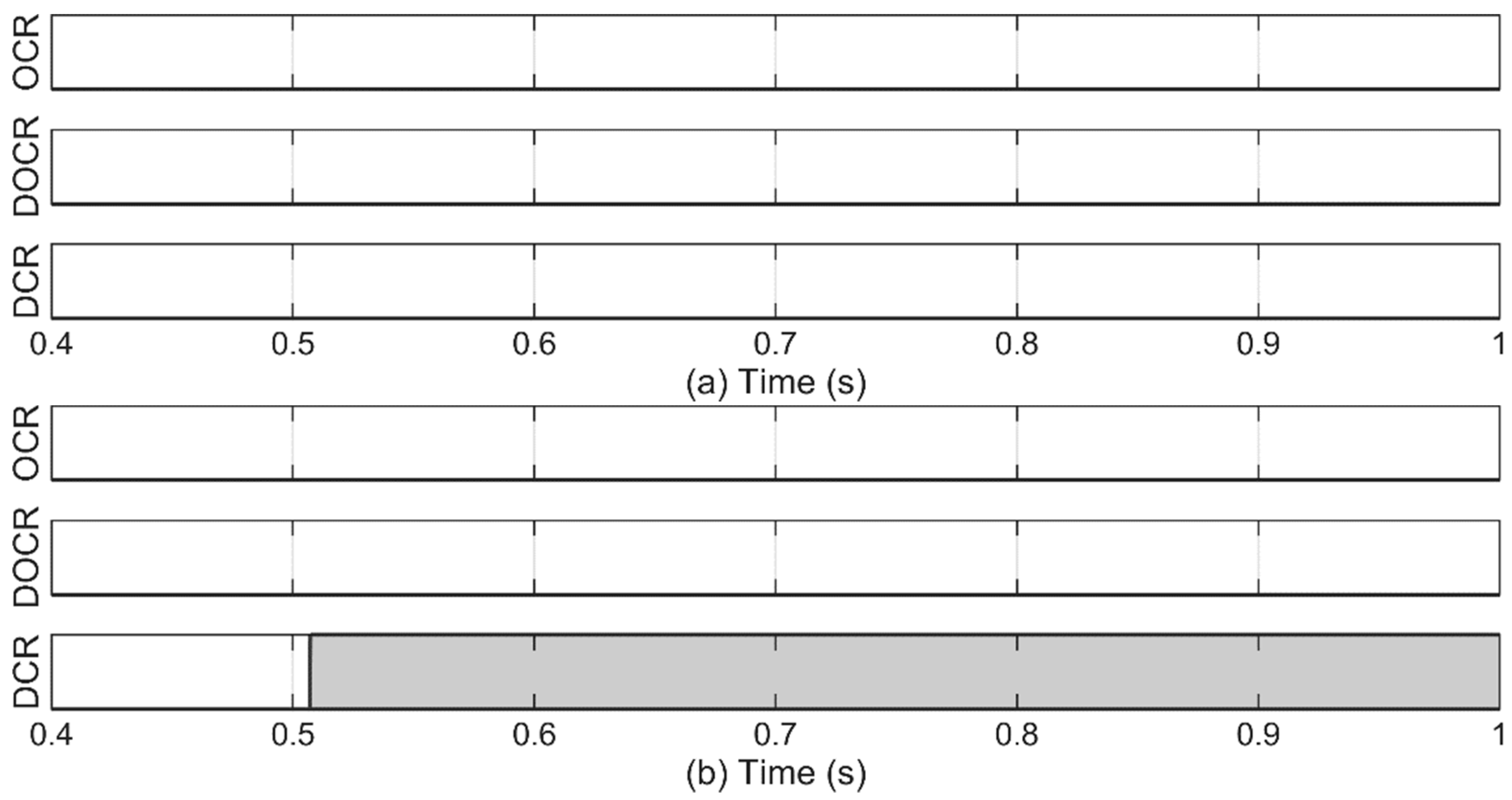
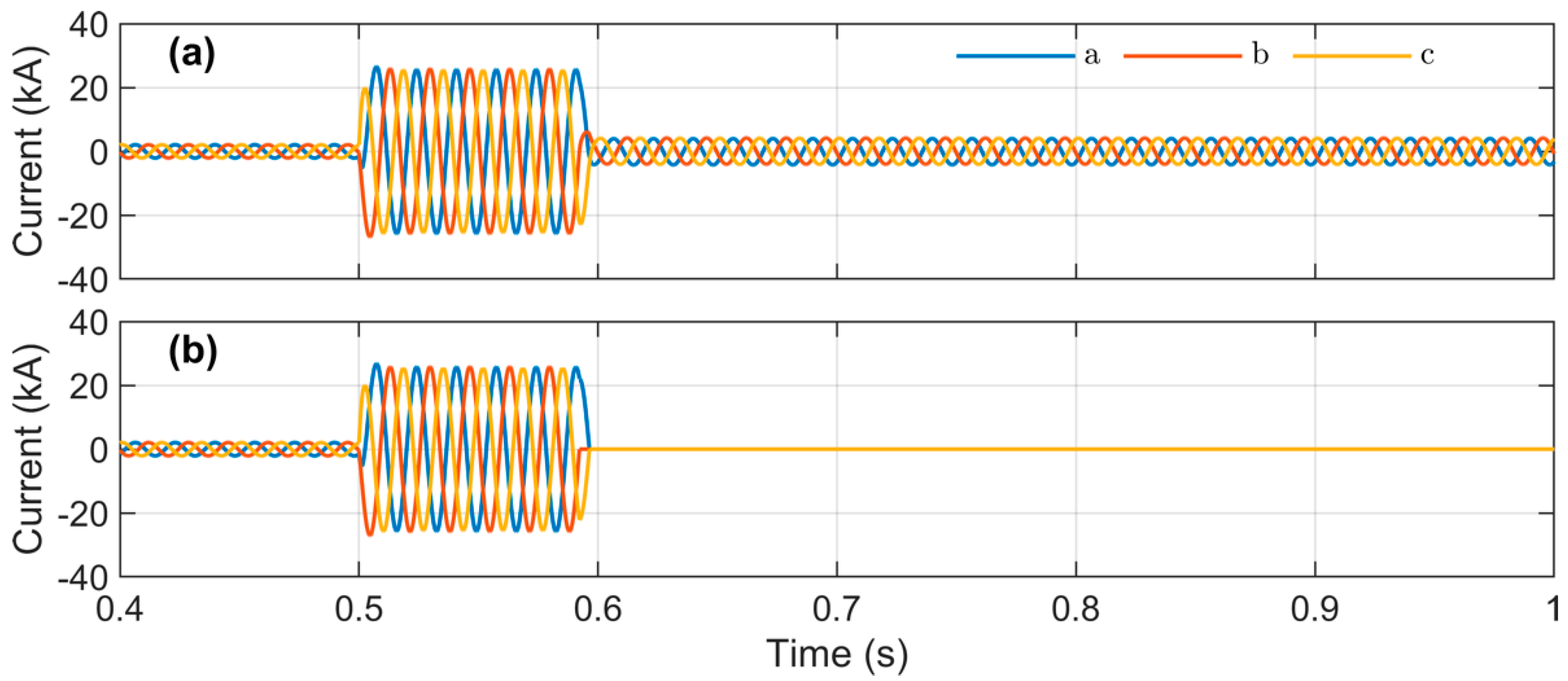
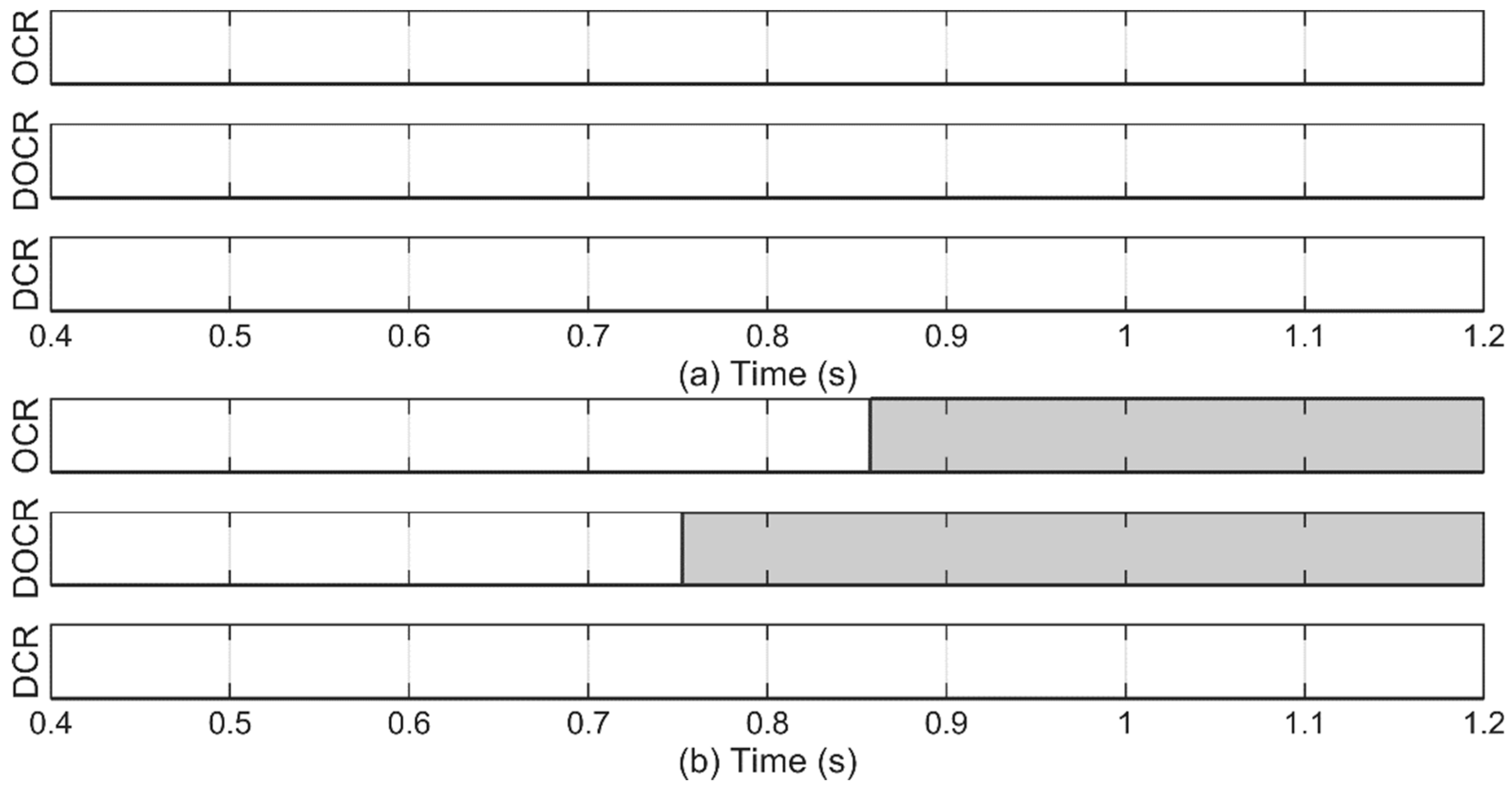
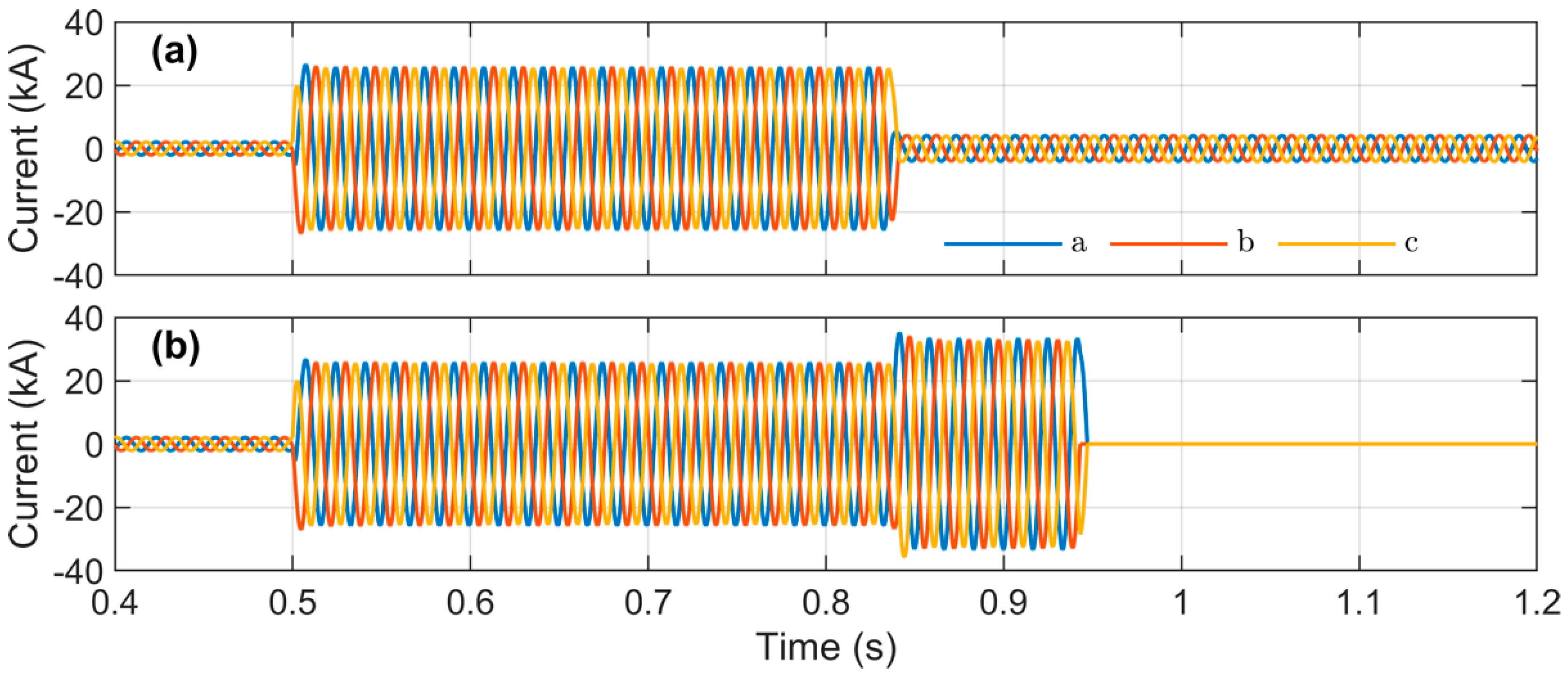
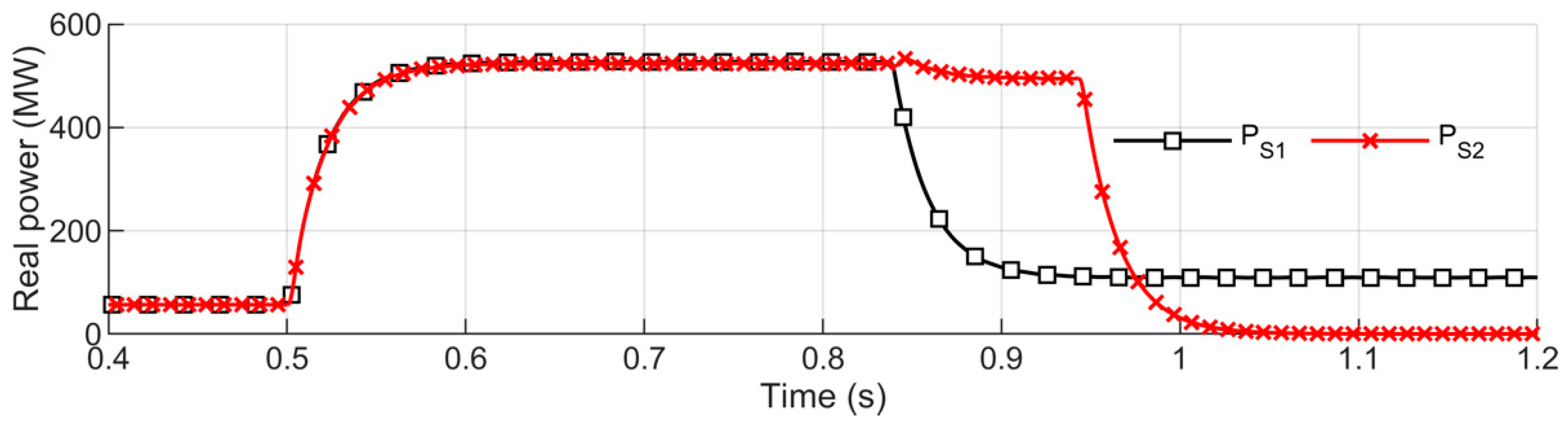
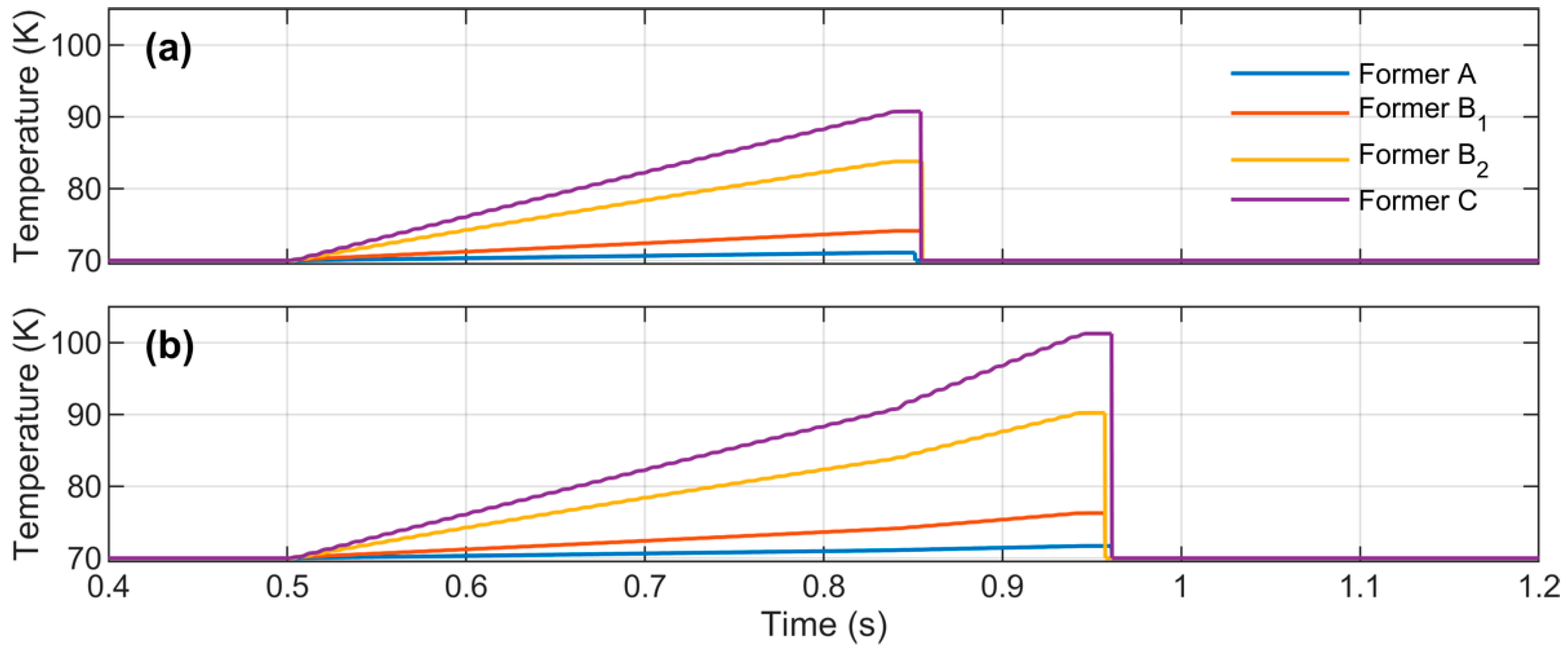
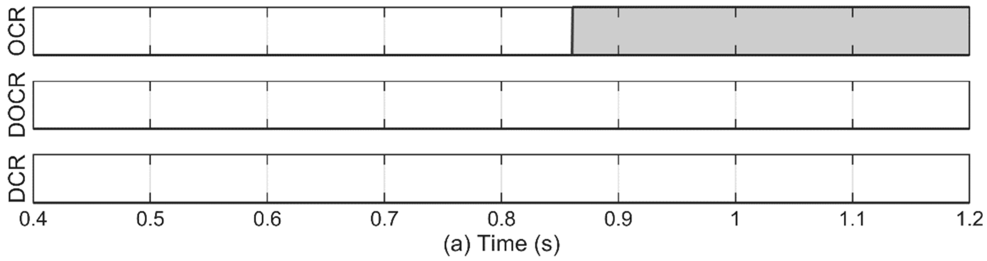
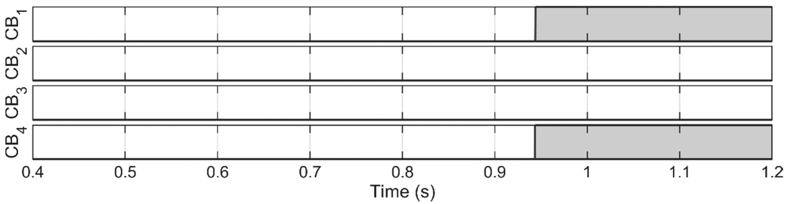
4.2. Case 2: Failure of DCR

It is assumed that the DCR of HTS2 fails to detect the internal fault of HTS2. The tested system shown in Figure 16 is used to evaluate the performance of backup protection. The tripping signals of relays are shown in Figure 17, in which the rising signal shows the fault identification of relays. It can be seen that the OCR and DOCR are operated to protect the power system from the fault. The fault occurs at 0.5 s and it is detected by DOCR at 0.76 s and OCR at 0.86 s. The rising signal in Figure 18 shows the opening status of CBs. CB3 and CB4 received the tripping signals from OCR and DOCR; after a five-cycle delay of the CB mechanism, two CBs are opened completely to protect the HTS cable.
Three-phase currents of two HTS cables are shown in Figure 19 and power flow into two cables is shown in Figure 20. Three-phase-to-ground fault occurred at 0.5 s and lead to a rapid increase of current and power through two HTS cables. The opening of CB3 at 0.84 s results in the reduction of current and power in HTS1 and the increase of current and power in HTS2. The fault is completely isolated at 0.94 s by opening CB4, which is indicated by the zero current and power of HTS2.
The resistances and temperatures of two HTS cables are shown in Figure 21 and Figure 22. It can be seen that the highest temperature rise is found at the former phase C of HTS2, which is about 102 K. It is observed that the backup protection of HTS2 is operated successfully to protect the power system from the internal fault at the HTS2.

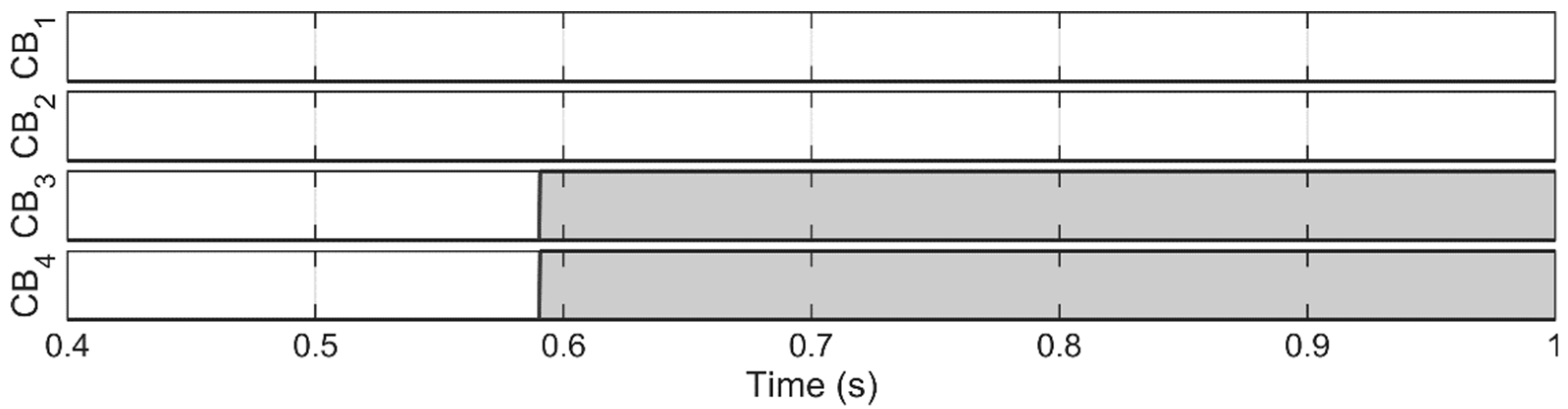
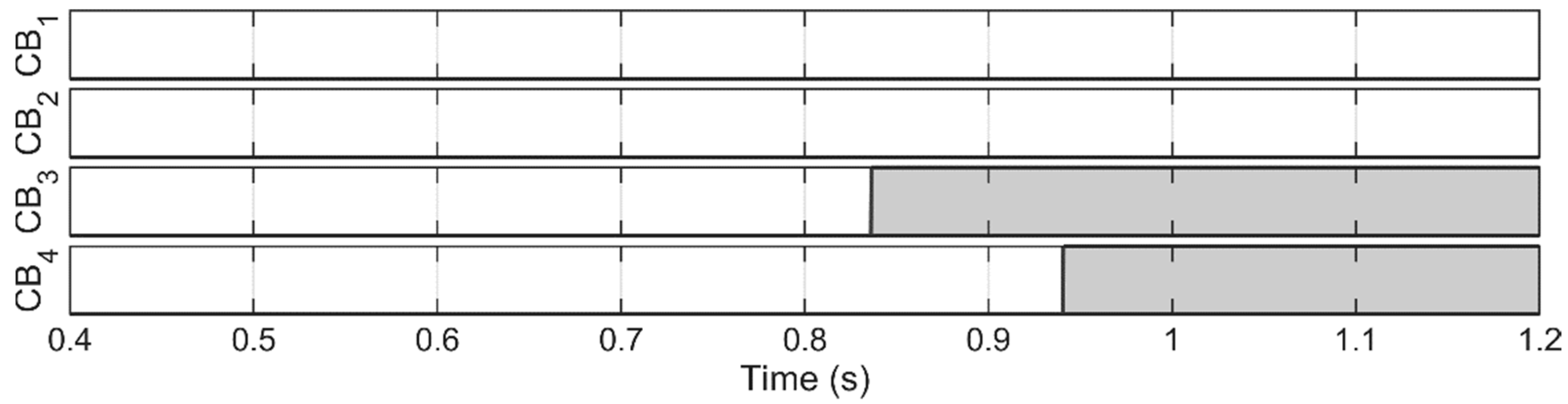
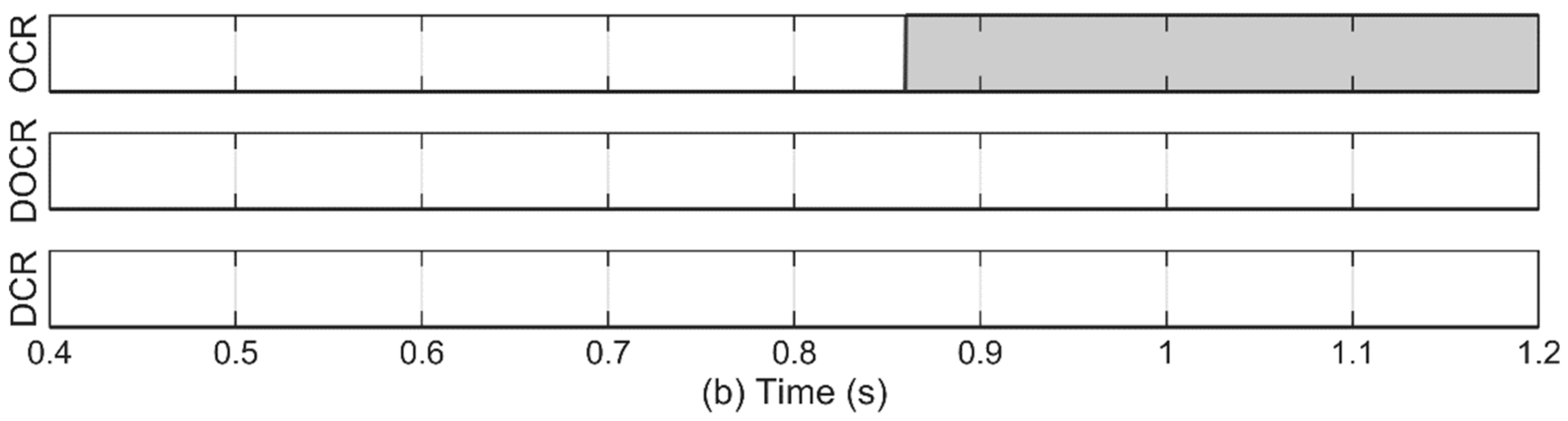
4.3. Case 3: Failures of DCR and DOCR

Finally, the failures of DCR and DOCR are considered to evaluate the coordinated protection of HTS1 and HTS2. The tested system, in this case, is shown in Figure 23. The operation of relays is shown in Figure 24, in which the rising signal represents the fault detection by relays. The fault occurs at 0.5 s, however, the main and backup protective relays (DCR and DOCR) fail to detect the fault. By using the proposed coordinated protection scheme, the internal fault is detected by two OCRs at 0.86 s. The rising signal in Figure 25 describes the CB opening status. The internal fault is completely isolated by opening CB1 and CB4 at 0.94 s.
Three-phase currents of two HTS cables are illustrated in Figure 26 and the power flows through two HTS cables are shown in Figure 27. The three-phase-to-ground fault at 0.5 s causes the rapid increase of current and power, in which the peak fault current is 27 kA and peak power is 520 MW. The fault is completely isolated by opening CB1 and CB4 at 0.94 s, resulting in the reduction of current and power of the two HTS cables to zero. The cable resistances are shown in Figure 28 and the cable temperatures are shown in Figure 29. The highest temperature rise is in the former phase C, which is about 98 K. It can be seen that the coordinated protection of two HTS cables is operated successfully to protect the HTS cable system from the fault.

5. Conclusions

This study has presented a fault analysis of the co-axial HTS cable in the mesh system and the design of the protection system to protect the HTS cable. The coordinated protection between the main and backup protective relays was presented to protect the HTS cable in cases of normal and abnormal relay operations. The main protection system was the DCR whereas the backup protections were the OCRs and DOCRs. In addition, the time-graded OCR was applied for the HTS cables as the secondary backup protection. Several scenarios were carried out to evaluate the transient fault current and the coordinated protection system. It was observed that the proposed protection system successfully protected the HTS cables either in the normal and abnormal operation of relays. The OCRs and DOCRs could protect the HTS cable in case the DCR fails to detect the fault. Unlike the conventional medium voltage cables, the HTS cable can conduct bulk power at the medium voltage, resulting in a very high conducting current. Thus, the selection of the current transformer (CT) for relays should be considered carefully in order to mitigate CT saturation, especially in the case of using DCR. Considering the abnormal relay operation and CB mechanism delay, it could take a long time to completely clear the fault, resulting in a significant increase in cable temperature. Thus, the coordination between the OCRs and the temperature relays of HTS cables should be taken into account. In addition, the experimental validation of the proposed protection scheme would be considered as our future works.

Author Contributions

Conceptualization, investigation, and writing—original draft preparation, T.-T.N.; visualization and editing, W.-G.L.; editing—review and supervision, H.-M.K.; funding acquisition, H.S.Y. All authors have read and agreed to the published version of the manuscript.

Funding

This work was funded by Korea Electric Power Corporation.

Acknowledgments

This work was supported by Research Assistance Program (2019) in the Incheon National University.

Conflicts of Interest

The authors declare no conflict of interest.

References

  1. Wesche, R. High-Temperature Superconductors. In Springer Handbook of Electronic and Photonic Materials; Springer International Publishing: Cham, Germany, 2017. [Google Scholar]
  2. Ge, J.-F.; Liu, Z.-L.; Liu, C.; Gao, C.-L.; Qian, D.; Xue, Q.-K.; Liu, Y.; Jia, J.-F. Superconductivity above 100 K in single-layer FeSe films on doped SrTiO3. Nat. Mater. 2015, 14, 285–289. [Google Scholar] [CrossRef] [PubMed]
  3. Lee, S.J.; Sung, H.J.; Park, M.; Won, D.Y.; Yoo, J.; Yang, H.S. Analysis of the temperature characteristics of three-phase coaxial superconducting power cable according to a liquid nitrogen circulation method for real-grid application in Korea. Energies 2019, 12, 1740. [Google Scholar] [CrossRef] [Green Version]
  4. Lee, S.J.; Park, M.; Yu, I.K.; Won, Y.; Kwak, Y.; Lee, C. Recent Status and Progress on HTS Cables for AC and DC Power Transmission in Korea. IEEE Trans. Appl. Supercond. 2018, 28, 1–5. [Google Scholar] [CrossRef]
  5. Ren, L.; Tang, Y.; Shi, J.; Li, L.; Li, J.; Cheng, S.C. Techno-Economic Feasibility Study on HTS Power Cables. IEEE Trans. Appl. Supercond. 2009, 19, 1774–1777. [Google Scholar] [CrossRef]
  6. Yang, B.; Kang, J.; Lee, S.; Choi, C.; Moon, Y. Qualification Test of a 80 kV 500 MW HTS DC Cable for Applying into Real Grid. IEEE Trans. Appl. Supercond. 2015, 25, 1–5. [Google Scholar] [CrossRef]
  7. Doukas, D.I.; Syrpas, A.; Labridis, D.P. Multiterminal DC Transmission Systems Based on Superconducting Cables Feasibility Study, Modeling, and Control. IEEE Trans. Appl. Supercond. 2018, 28, 1–6. [Google Scholar] [CrossRef]
  8. Leon Garcia, W.R.; Tixador, P.; Raison, B.; Bertinato, A.; Luscan, B.; Creusot, C. Technical and Economic Analysis of the R-Type SFCL for HVDC Grids Protection. IEEE Trans. Appl. Supercond. 2017, 27, 1–9. [Google Scholar] [CrossRef]
  9. Lee, C.; Choi, J.; Yang, H.; Park, M.; Iwakuma, M. Economic Evaluation of 23 kV Tri-Axial HTS Cable Application to Power System. IEEE Trans. Appl. Supercond. 2019, 29, 5402507. [Google Scholar] [CrossRef]
  10. Stemmle, M.; Merschel, F.; Noe, M.; Hofmann, L.; Hobl, A. Novel grid concepts for urban area power supply. Phys. Procedia 2012, 36, 884–889. [Google Scholar] [CrossRef] [Green Version]
  11. Yoon, J.Y.; Lee, S.R.; Kim, J.Y. Application methodology for 22.9 kV HTS cable in metropolitan city of South Korea. IEEE Trans. Appl. Supercond. 2007, 17, 1656–1660. [Google Scholar] [CrossRef]
  12. Li, J.; Zhao, Z.; Shu, B.; Han, X.; Ma, X.; Bian, B.; Li, J.; Liang, Z. Fault Analysis for 110 kV HTS Power Cables. IEEE Trans. Appl. Supercond. 2014, 24, 1–5. [Google Scholar] [CrossRef]
  13. Dinh, M.C.; Ju, C.H.; Kim, J.G.; Park, M.; Yu, I.K.; Yang, B. Transient analysis of an HTS DC power cable with an HVDC system. Phys. C Supercond. Appl. 2013, 494, 311–318. [Google Scholar] [CrossRef]
  14. Wang, X.; Ishiyama, A.; Ohya, M.; Fujiwara, N. Over-current characteristics of 66-kV RE123 HTS power cable. IEEE Trans. Appl. Supercond. 2011, 21, 1013–1016. [Google Scholar] [CrossRef]
  15. Kim, J.H.; Park, M.; Ali, M.H.; Cho, J.; Yoon, J.Y.; Lee, S.R.; Yu, I.K. RTDS analysis of the fault currents characteristics of HTS power cable in utility power network. IEEE Trans. Appl. Supercond. 2008, 18, 684–688. [Google Scholar] [CrossRef]
  16. Lee, S.R.; Lee, J.J.; Yoon, J.; Kang, Y.W.; Hur, J. Impact of 154-kV HTS Cable to Protection Systems of the Power Grid in South Korea. IEEE Trans. Appl. Supercond. 2016, 26, 4–7. [Google Scholar] [CrossRef]
  17. Kim, J.H.; Park, M.; Park, I.K.; Lee, S.R.; Park, J.D.; Kwon, Y.K.; Yu, I.K. A study on the improvement of protective relay system for the utility application of HTS power cable. Phys. C Supercond. Appl. 2009, 469, 1873–1877. [Google Scholar] [CrossRef]
  18. Kim, J.H.; Park, M.; Yu, I.K. Development of real time protective coordination algorithm for HTS power cable. IEEE Trans. Appl. Supercond. 2015, 25, 1–4. [Google Scholar] [CrossRef]
  19. Hou, J.; Wei, B.; Chen, P.; Zhao, Y.; Gao, C.; Qiu, M.; Zhang, G. The research of protection strategy for 110 kV cold dielectric high temperature superconducting power cable. IEEE Trans. Appl. Supercond. 2013, 23, 5400304. [Google Scholar]
  20. Lee, H.; Jung, C.; Song, C.S.; Lee, S.R.; Yang, B.M.; Jang, G. Novel protection scheme with the superconducting power cables and fault current limiters through rtds test in icheon substation. IEEE Trans. Appl. Supercond. 2012, 22, 4705304. [Google Scholar]
  21. Nguyen, T.; Lee, W.-G.; Lee, S.; Park, M.; Kim, H.; Won, D.; Yoo, J.; Yang, H.S. A Simplified Model of Coaxial, Multilayer High-Temperature Superconducting Power Cables with Cu Formers for Transient Studies. Energies 2019, 12, 1514. [Google Scholar] [CrossRef] [Green Version]
  22. De Andrade, V.; Sorrentino, E. Typical Expected Values of the Fault Resistance in Power Systems. In Proceedings of the 2010 IEEE/PES Transmission and Distribution Conference and Exposition: Latin America (T&D-LA), Sao Paulo, Brazil, 8–10 November 2010; pp. 602–609. [Google Scholar]
Figure 1. Tested system and configuration of co-axial high-temperature superconducting (HTS) cable.
Energies 13 00220 g001
Figure 2. Operation characteristic and equivalent scheme of co-axial HTS cable adopted from [21]: (a) current flow into each phase in the normal state; (b) current flow into each phase in the transient state; (c) equivalent circuit of the HTS power cable.
Energies 13 00220 g002
Figure 3. Coordinated protection of the tested system.
Energies 13 00220 g003
Figure 4. Process of designing protective relays.
Energies 13 00220 g004
Figure 5. Characteristic curve of directional overcurrent relays (DCR).
Energies 13 00220 g005
Figure 6. Implementation of DCR in PSCAD/EMTDC.
Energies 13 00220 g006
Figure 7. Grading scheme of the tested system.
Energies 13 00220 g007
Figure 8. Protection coordination for the HTS cable system.
Energies 13 00220 g008
Figure 9. Tested system.
Energies 13 00220 g009
Figure 10. Relay trip signals in case DCRs operate normally: (a) relays in HTS1; (b) relays in HTS2.
Energies 13 00220 g010
Figure 11. Operation of circuit breakers in case DCRs operate normally.
Energies 13 00220 g011
Figure 12. Currents in HTS cables in case DCRs operate normally: (a) HTS1; (b) HTS2.
Energies 13 00220 g012
Figure 13. Conducted power in HTS cables in case DCRs operate normally.
Energies 13 00220 g013
Figure 14. HTS cable resistances in case DCRs operate normally: (a) HTS1; (b) HTS2.
Energies 13 00220 g014
Figure 15. HTS cable temperatures in case DCRs operate normally: (a) HTS1; (b) HTS2.
Energies 13 00220 g015
Figure 16. Tested system in case of DCR failure.
Energies 13 00220 g016
Figure 17. Relay trip signals in case DCR fails: (a) relays in HTS1; (b) relays in HTS2.
Energies 13 00220 g017
Figure 18. Operation of circuit breakers in case DCR fails.
Energies 13 00220 g018
Figure 19. Currents in HTS cables in case DCR fails: (a) HTS1; (b) HTS2.
Energies 13 00220 g019
Figure 20. Conducted power in HTS cables in case DCR fails.
Energies 13 00220 g020
Figure 21. HTS cable resistances in case DCR fails: (a) HTS1; (b) HTS2.
Energies 13 00220 g021
Figure 22. HTS cable temperatures in case DCR fails: (a) HTS1; (b) HTS2.
Energies 13 00220 g022
Figure 23. Tested system in case DCR and DOCR fail.
Energies 13 00220 g023
Figure 24. Relay trip signals in case DCR and DOCR fail: (a) relays in HTS1; (b) relays in HTS2.
Energies 13 00220 g024aEnergies 13 00220 g024b
Figure 25. Operation of circuit breakers in case DCR and DOCR fail.
Energies 13 00220 g025
Figure 26. Currents in HTS cables in case DCR and DOCR fail: (a) HTS1; (b) HTS2.
Energies 13 00220 g026
Figure 27. Conducted power in HTS cables in case DCR and DOCR fail.
Energies 13 00220 g027
Figure 28. HTS cable resistances in case DCR and DOCR fail: (a) HTS1; (b) HTS2.
Energies 13 00220 g028
Figure 29. HTS cable temperatures in case DCR and DOCR fail: (a) HTS1; (b) HTS2.
Energies 13 00220 g029
Table 1. System parameters.
ParameterSymbolValue
Nominal frequency f 60 Hz
Cable length L 1 km
Critical current I c 5 kA
Resistance of HTS layer at normal state R H T S _ n o r m   0.00000063 Ω/m
Resistance of HTS layer at transient state R H T S _ n o r m   2.5 m Ω/m
Table 2. Trip characteristic constants.
ConstantValue
A 39.85
B 1.084
p 1.95

