Supercapacitor Storage Sizing Analysis for a Series Hybrid Vehicle

 ,
,  ,
, 
 and
and
Abstract
:1. Introduction
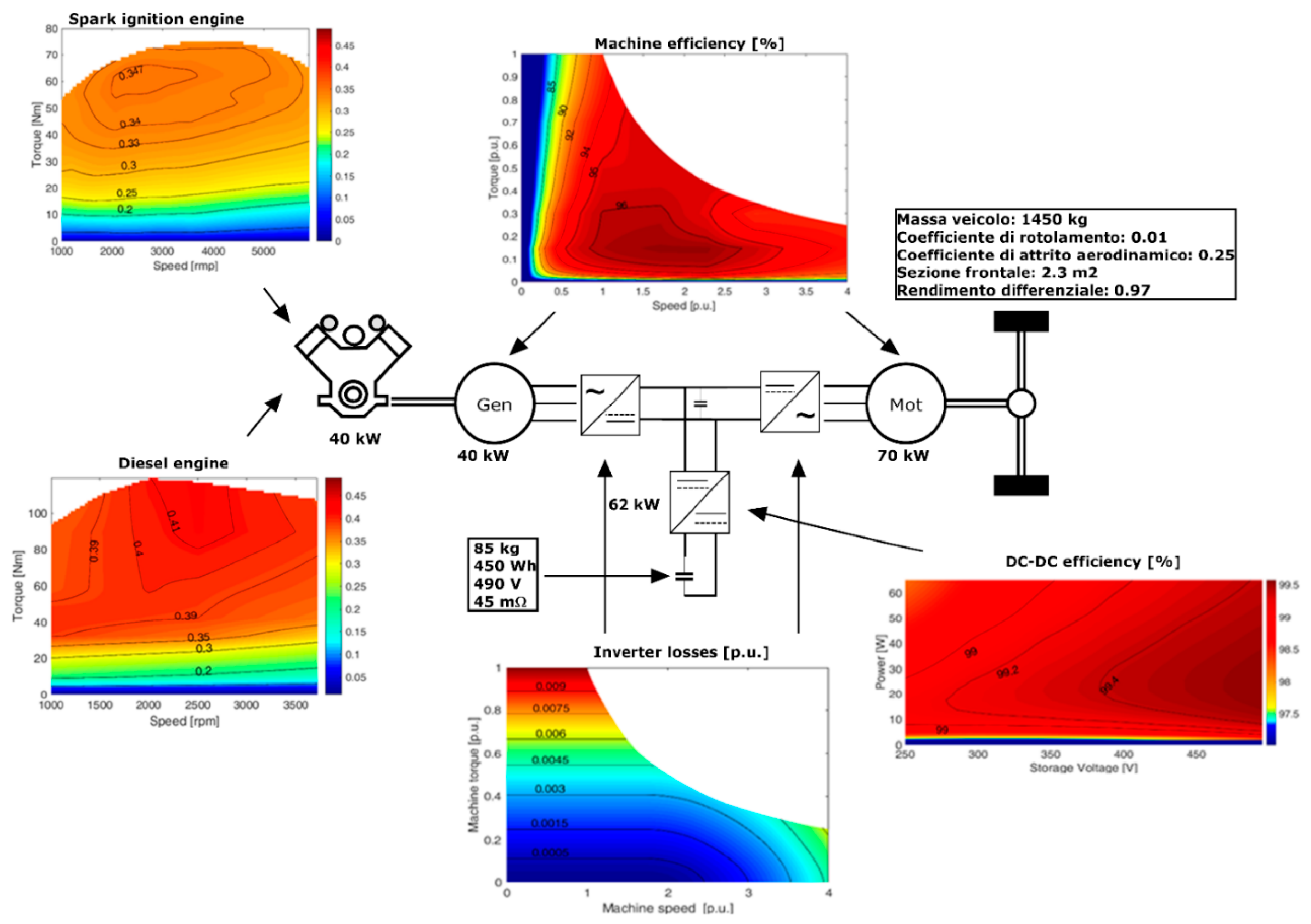
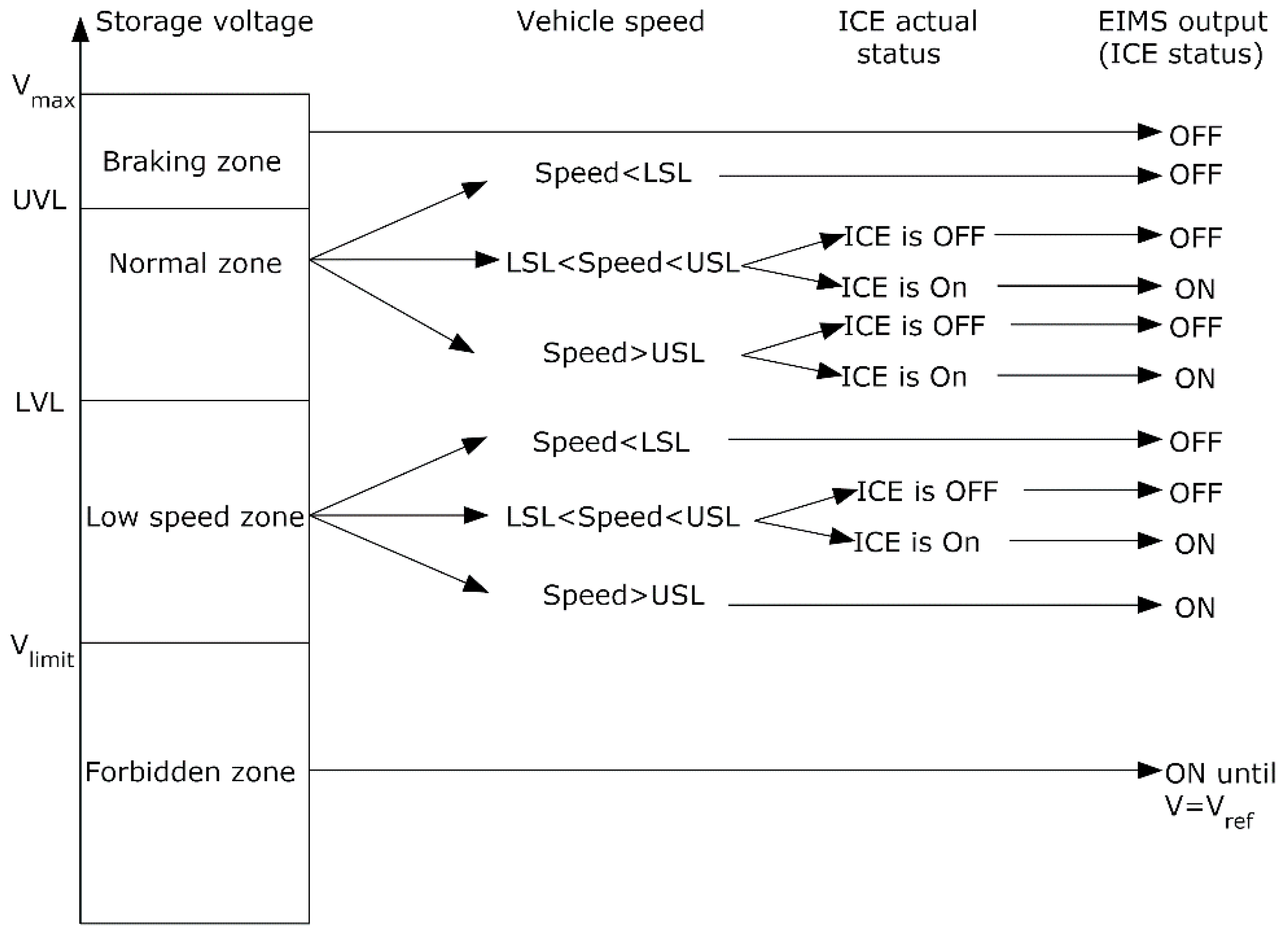
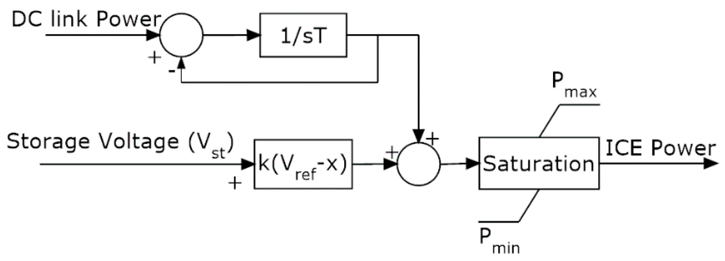
2. Series Architecture and Energy Management System (EMS)
- Braking zone (UVL < V < Vmax):
- Normal zone (LVL < V < UVL)
- Low speed zone (Vlimit < V < LVL)
- Forbidden zone (V < Vlimit)
3. Storage Zones Analysis and Sizing Optimization
- Braking Zone (BZ): if the braking zone is too small, there is a small quantity of energy available for regenerative braking. This influences powertrain efficiency, especially in missions characterized by long downhill roads. As a matter of fact, when the storage system reaches Vmax the extra backward energy has to be dissipated on mechanical brakes.
- Normal Zone (NZ): if this zone is too small, the storage system charges and discharges quickly; as a consequence, ICE number of starts increases significantly.
- Low Speed Zone (LSZ): the aim of this zone is to avoid engine use at low speed. Indeed, one of hybrid vehicle aims is to guarantee electric traction at low speed. If the low speed zone is limited, ICE starts when vehicle speed is low (i.e., below USL) may occur frequently.
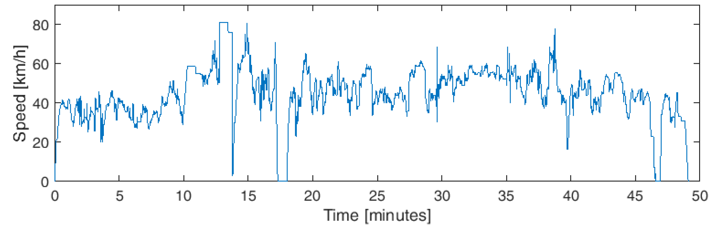
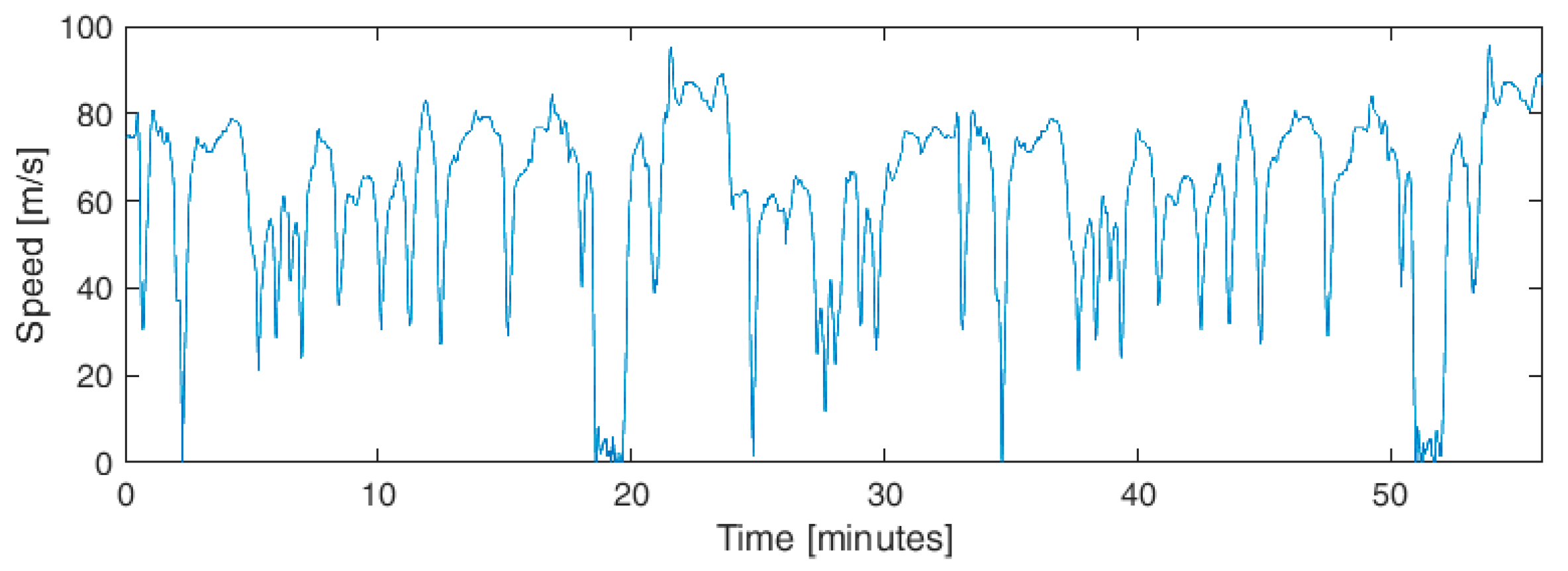
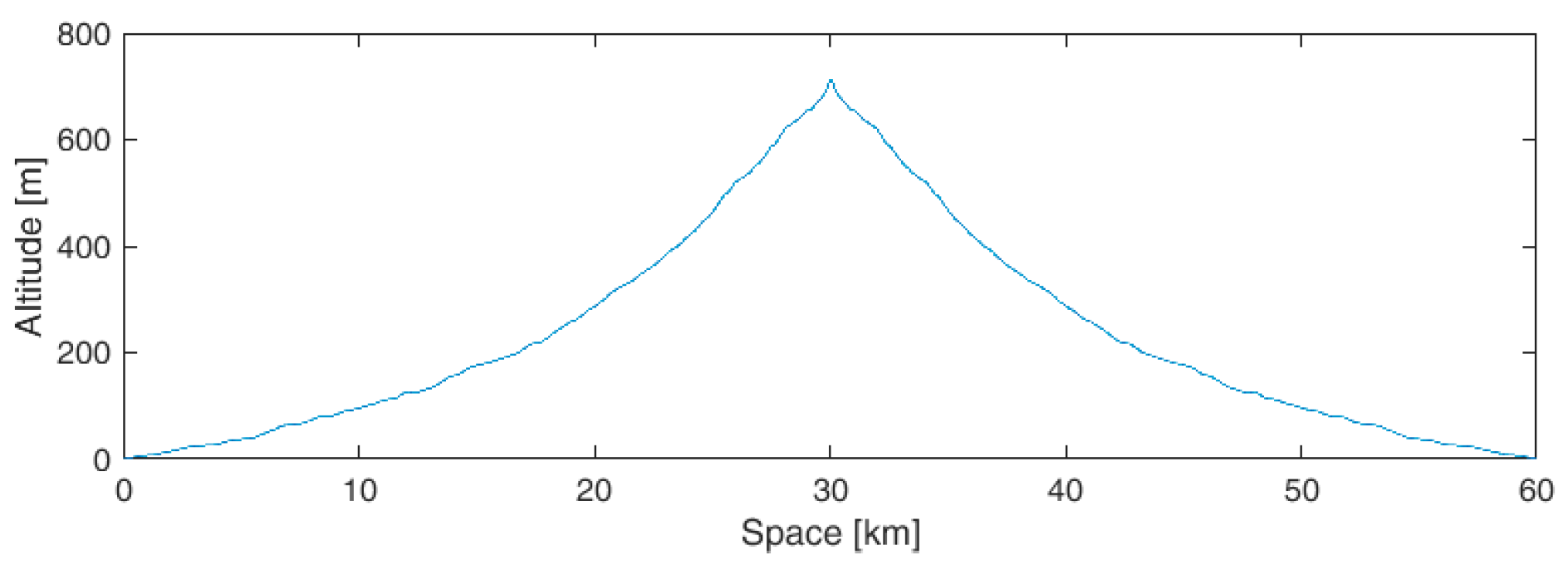
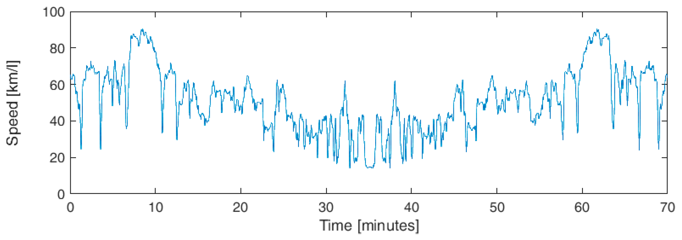
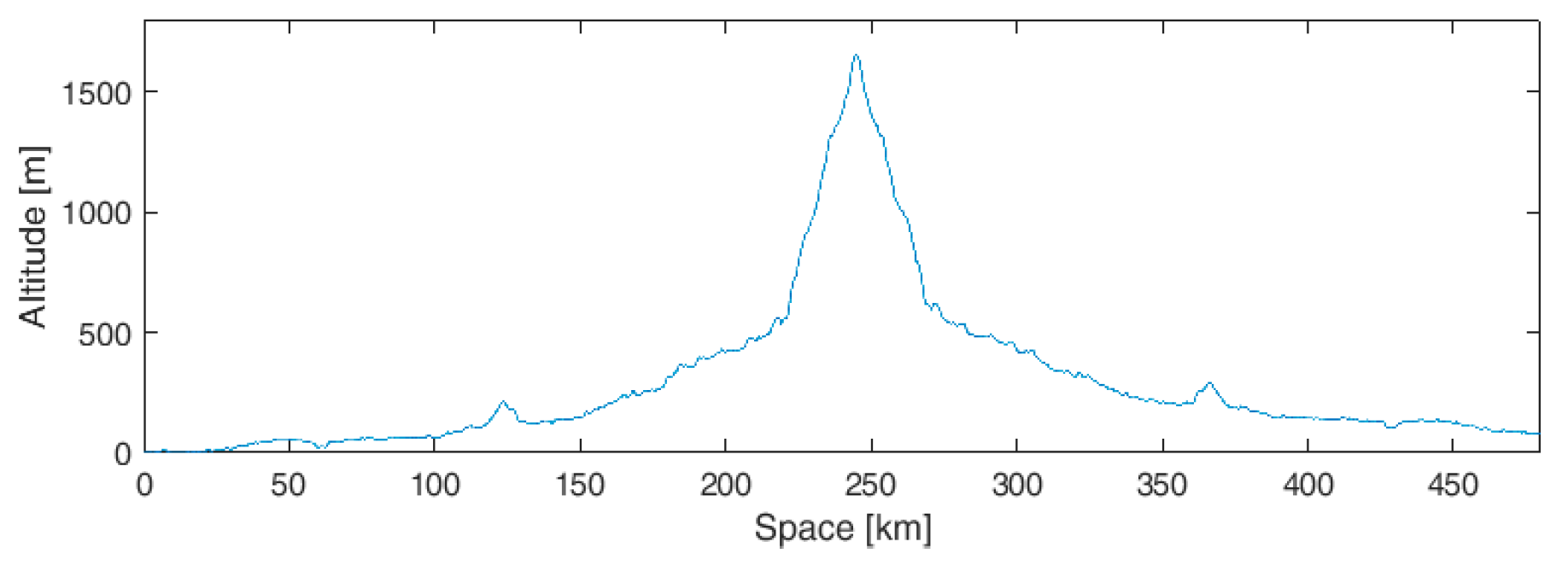
4. Road Missions
- Urban: 11 km inside Aosta (Italy) town center.
- Fast-urban: from University of Genova, Albaro district (Genoa, Italy) to Bogliasco (Genoa, Italy) and return.
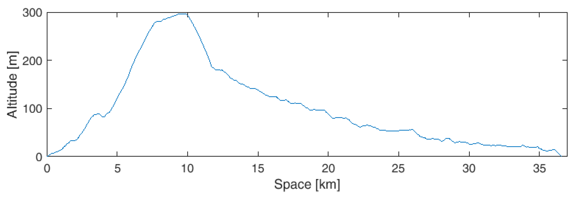
- Extra-urban 1: from University of Genova, Albaro district (Genoa, Italy) to Lavagna (Genoa, Italy) via Bargagli (Genoa, Italy).
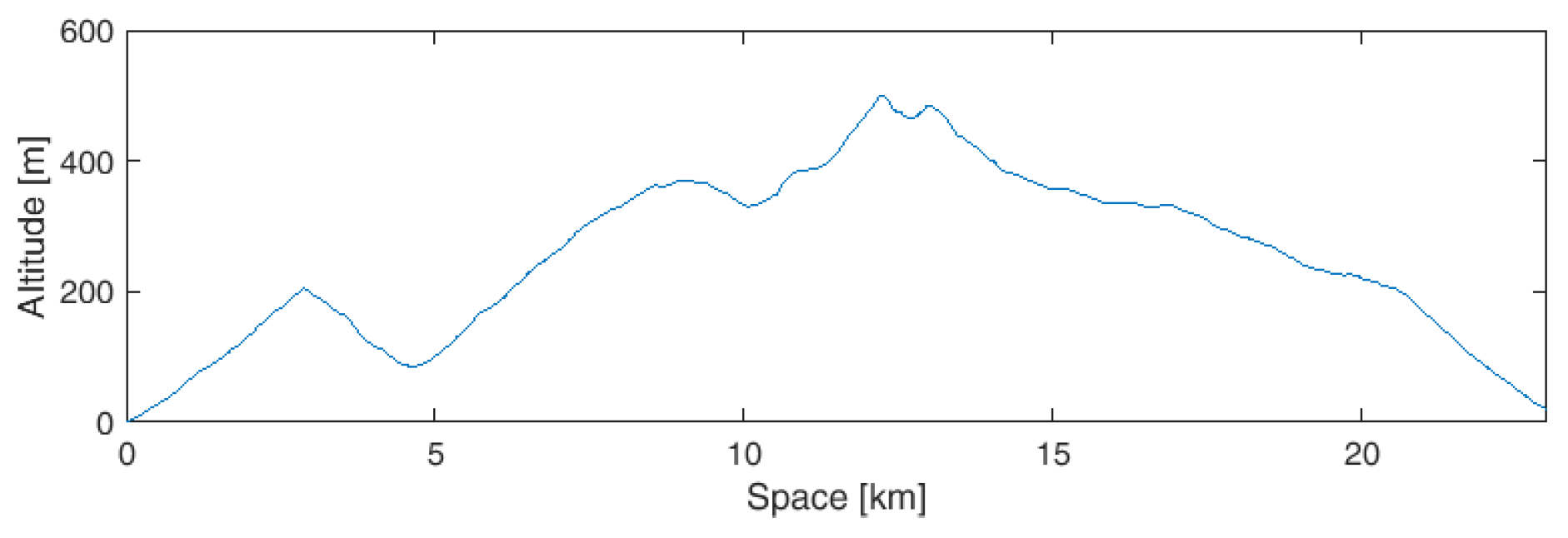
- Mountain mission 1: Champorcher valley (Aosta, Italy) and return.
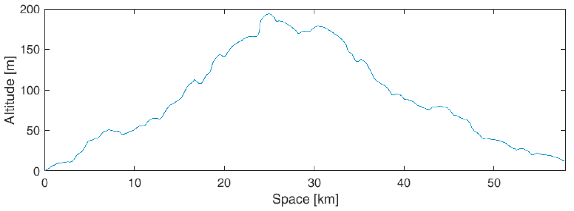
- Extra-urban 2: from Boves (Cuneo, Italy) to Mondovì (Cuneo, Italy).
- Mountain mission 2: from Boves (Cuneo, Italy) to Limonetto (Cuneo, Italy) and return.
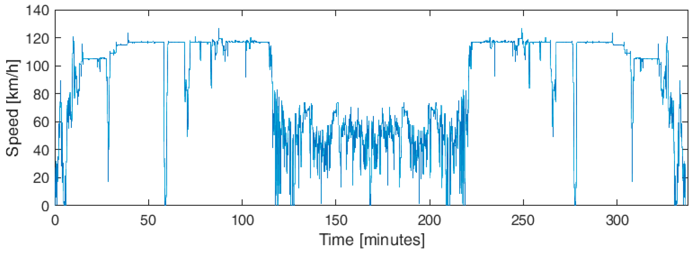
- Highway + Mountain: from Milan (Italy) to Pont (Valsavaranche, Aosta, Italy) and return.
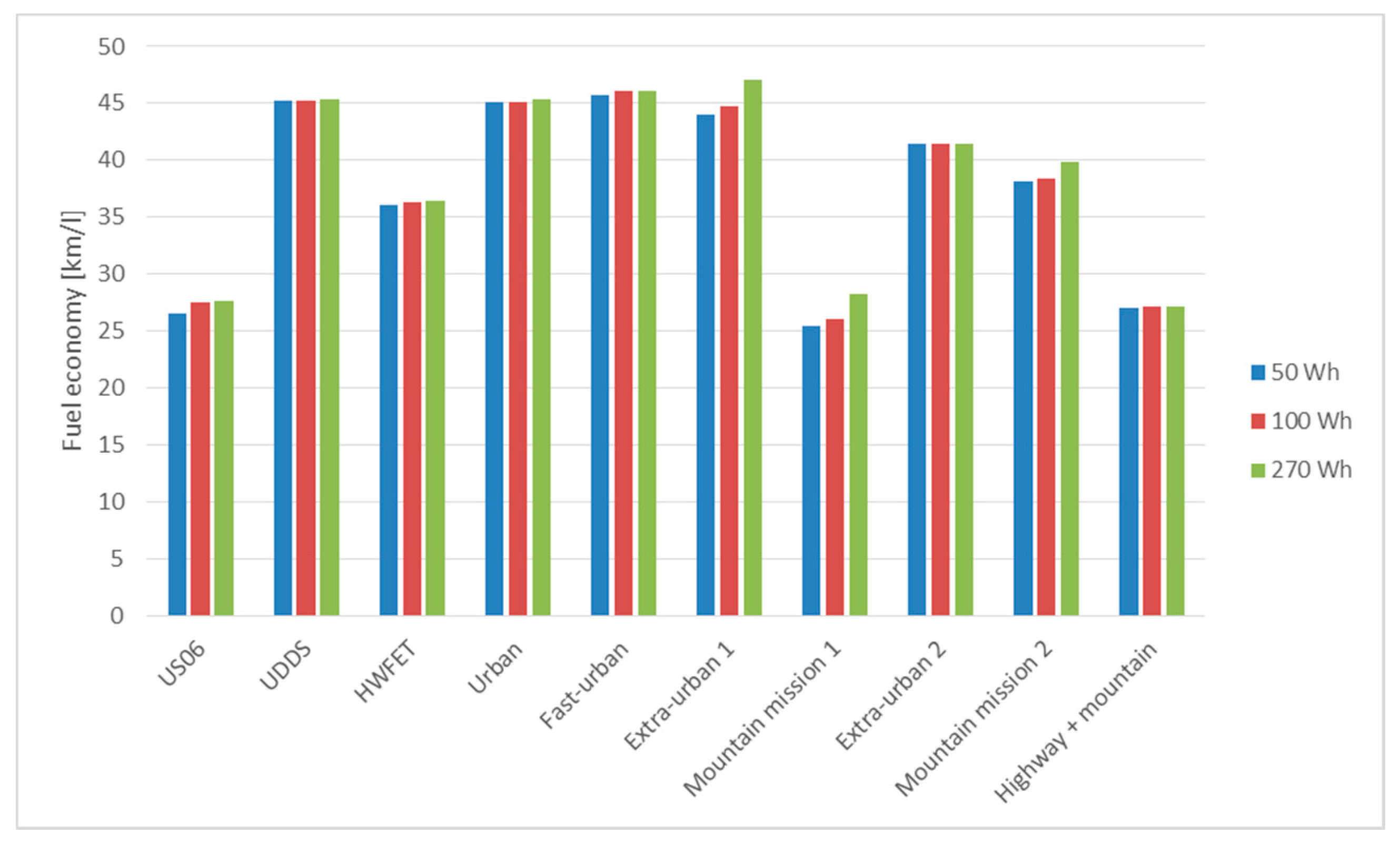
5. Simulation Results
5.1. Normal Zone Sizing
5.2. Low Speed Zone Sizing
5.3. Braking Zone Sizing
6. Conclusions
Author Contributions
Funding
Conflicts of Interest
References
- Capata, R. Urban and extra-urban hybrid vehicles: A technological review. Energies 2018, 11, 2924. [Google Scholar] [CrossRef]
- Salmasi, F.R. Control strategies for hybrid electric vehicles: Evolution, classification, comparison, and future trends. IEEE Trans. Veh. Technol. 2007, 56, 2393–2404. [Google Scholar] [CrossRef]
- Uebel, S.; Murgovski, N.; Tempelhahn, C.; Bäker, B. Optimal energy management and velocity control of hybrid electric vehicles. IEEE Trans. Veh. Technol. 2017, 67, 327–337. [Google Scholar] [CrossRef]
- Millo, F.; Cubito, C.; Rolando, L.; Pautasso, E.; Servetto, E. Design and development of an hybrid light commercial vehicle. Energy 2017, 136, 90–99. [Google Scholar] [CrossRef]
- Chen, S.-Y.; Wu, C.-H.; Hung, Y.-H.; Chung, C.-T. Optimal strategies of energy management integrated with transmission control for a hybrid electric vehicle using dynamic particle swarm optimization. Energy 2018, 160, 154–170. [Google Scholar] [CrossRef]
- Zhang, F.; Liu, H.; Hu, Y.; Xi, J. A supervisory control algorithm of hybrid electric vehicle based on adaptive equivalent consumption minimization strategy with fuzzy pi. Energies 2016, 9, 919. [Google Scholar] [CrossRef]
- Hu, Y.; Li, W.; Xu, H.; Xu, G. An online learning control strategy for hybrid electric vehicle based on fuzzy q-learning. Energies 2015, 8, 11167–11168. [Google Scholar] [CrossRef]
- Finesso, R.; Misul, D.; Spessa, E.; Venditti, M. Optimal design of power-split hevs based on total cost of ownership and co2 emission minimization. Energies 2018, 11, 1705. [Google Scholar] [CrossRef]
- Burress, T.A.; Campbell, S.L.; Coomer, C.L.; Ayers, C.W.; Wereszczak, A.A.; Cunningham, J.P.; Marlino, L.D.; Seiber, L.E.; Lin, H.T. Evaluation of the 2010 Toyota Prius Hybrid Synergy Drive System; Power Electronics and Electric Machinery Research Facility, Technical Report ORNL/TM2010/253; Oak Ridge National Laboratory (ORNL): Oak Ridge, TN, USA, 2011. [Google Scholar]
- Kim, N.; Cha, S.; Peng, H. Optimal control of hybrid electric vehicles based on pontryagin’s minimum principle. IEEE Trans. Control Syst. Technol. 2011, 19, 1279–1287. [Google Scholar]
- Bonfiglio, A.; Lanzarotto, D.; Marchesoni, M.; Passalacqua, M.; Procopio, R.; Repetto, M. Electrical-loss analysis of power-split hybrid electric vehicles. Energies 2017, 10, 2142. [Google Scholar] [CrossRef]
- Cipek, M.; Pavković, D.; Petrić, J. A control-oriented simulation model of a power-split hybrid electric vehicle. Appl. Energy 2013, 101, 121–133. [Google Scholar] [CrossRef]
- Pei, H.; Hu, X.; Yang, Y.; Tang, X.; Hou, C.; Cao, D. Configuration optimization for improving fuel efficiency of power split hybrid powertrains with a single planetary gear. Appl. Energy 2018, 214, 103–116. [Google Scholar] [CrossRef]
- Xiang, C.; Ding, F.; Wang, W.; He, W. Energy management of a dual-mode power-split hybrid electric vehicle based on velocity prediction and nonlinear model predictive control. Appl. Energy 2017, 189, 640–653. [Google Scholar] [CrossRef]
- Xu, Q.; Mao, Y.; Zhao, M.; Cui, S. A hybrid electric vehicle dynamic optimization energy management strategy based on a compound-structured permanent-magnet motor. Energies 2018, 11, 2212. [Google Scholar] [CrossRef]
- Chen, J.; Du, J.; Wu, X. Fuel economy analysis of series hybrid electric bus with idling stop strategy. In Proceedings of the 2014 9th International Forum on Strategic Technology (IFOST), Cox’s Bazar, Bangladesh, 21–23 October 2014; pp. 359–362. [Google Scholar]
- Kim, M.; Jung, D.; Min, K. Hybrid thermostat strategy for enhancing fuel economy of series hybrid intracity bus. IEEE Trans. Veh. Technol. 2014, 63, 3569–3579. [Google Scholar] [CrossRef]
- Zhao, Y.; Yao, J.; Zhong, Z.M.; Sun, Z.C. The research of powertrain for supercapacitor-based series hybrid bus. In Proceedings of the 2008 IEEE Vehicle Power and Propulsion Conference, Harbin, China, 3–5 September 2008; pp. 1–4. [Google Scholar]
- Maxwell Supercapacitor. Available online: www.maxwell.com (accessed on 8 May 2019).
- Ultimo Supercapacitor. Available online: https://www.jsrmicro.be/emerging-technologies/lithium-ion-capacitor/products/ultimo-lithium-ion-capacitor-laminate-cells-lic (accessed on 8 May 2019).
- Cao, J.; Emadi, A. A new battery/ultracapacitor hybrid energy storage system for electric, hybrid, and plug-in hybrid electric vehicles. IEEE Trans. Power Electron. 2012, 27, 122–132. [Google Scholar]
- Marchesoni, M.; Vacca, C. New DC–DC converter for energy storage system interfacing in fuel cell hybrid electric vehicles. IEEE Trans. Power Electron. 2007, 22, 301–308. [Google Scholar] [CrossRef]
- Laldin, O.; Moshirvaziri, M.; Trescases, O. Predictive algorithm for optimizing power flow in hybrid ultracapacitor/battery storage systems for light electric vehicles. IEEE Trans. Power Electron. 2013, 28, 3882–3895. [Google Scholar] [CrossRef]
- Marchesoni, M.; Savio, S. Reliability analysis of a fuel cell electric city car. In Proceedings of the 2005 European Conference on Power Electronics and Applications, Dresden, Germany, 11–14 September 2005; p. 10. [Google Scholar]
- Carpaneto, M.; Ferrando, G.; Marchesoni, M.; Savio, S. A new conversion system for the interface of generating and storage devices in hybrid fuel-cell vehicles. In Proceedings of the IEEE International Symposium on Industrial Electronics, ISIE 2005, Dubrovnik, Croatia, 20–23 June 2005; pp. 1477–1482. [Google Scholar]
- Kim, H.; Chen, H.; Zhu, J.; Maksimović, D.; Erickson, R. Impact of 1.2 kV SIC-MOSFET EV traction inverter on urban driving. In Proceedings of the 2016 IEEE 4th Workshop on Wide Bandgap Power Devices and Applications (WiPDA), Fayetteville, AR, USA, 7–9 November 2016; pp. 78–83. [Google Scholar]
- Ding, X.; Cheng, J.; Chen, F. Impact of silicon carbide devices on the powertrain systems in electric vehicles. Energies 2017, 10, 533. [Google Scholar] [CrossRef]
- Lanzarotto, D.; Marchesoni, M.; Passalacqua, M.; Prato, A.P.; Repetto, M. Overview of different hybrid vehicle architectures. IFAC-PapersOnLine 2018, 51, 218–222. [Google Scholar] [CrossRef]
- Passalacqua, M.; Lanzarotto, D.; Repetto, M.; Vaccaro, L.; Bonfiglio, A.; Marchesoni, M. Fuel economy and energy management system for a series hybrid vehicle based on supercapacitor storage. IEEE Trans. Power Electron. 2019. [Google Scholar] [CrossRef]
- Zhang, L.; Hu, X.; Wang, Z.; Sun, F.; Deng, J.; Dorrell, D.G. Multiobjective optimal sizing of hybrid energy storage system for electric vehicles. IEEE Trans. Veh. Technol. 2018, 67, 1027–1035. [Google Scholar] [CrossRef]
- Snoussi, J.; Elghali, S.B.; Benbouzid, M.; Mimouni, M.F. Optimal sizing of energy storage systems using frequency-separation-based energy management for fuel cell hybrid electric vehicles. IEEE Trans. Veh. Technol. 2018, 67, 9337–9346. [Google Scholar] [CrossRef]
- Epa. Available online: https://www.epa.gov/vehicle-and-fuel-emissions-testing/dynamometer-drive-schedules (accessed on 8 May 2019).
- Passalacqua, M.; Lanzarotto, D.; Repetto, M.; Marchesoni, M. Advantages of using supercapacitors and silicon carbide on hybrid vehicle series architecture. Energies 2017, 10, 920. [Google Scholar] [CrossRef]
- Di Cairano, S.; Liang, W.; Kolmanovsky, I.V.; Kuang, M.L.; Phillips, A.M. Power smoothing energy management and its application to a series hybrid powertrain. IEEE Trans. Control Syst. Technol. 2013, 21, 2091–2103. [Google Scholar] [CrossRef]
- Ortner, P.; Del Re, L. Predictive control of a diesel engine air path. IEEE Trans. Control Syst. Technol. 2007, 15, 449–456. [Google Scholar] [CrossRef]


| Feature | EDLC SC | Lithium SC |
|---|---|---|
| Cell energy density | 7–8 Wh/kg | 10–13 Wh/kg |
| Package energy density 1 | 3.5–4 Wh/kg | 5–7 Wh/kg |
| Cell maximum voltage | 2.8–3 V | 3.8 V |
| Round trip efficiency at 120 s 2 | 96–98% | 94–97% |
| Missions | Average Speed [km/h] | Maximum Speed [km/h] | Length [km] | Time [Minutes] | Change of Altitude [m] |
|---|---|---|---|---|---|
| US06 | 78 | 130 | 13 | 10 | - |
| UDDS | 31 | 90 | 12 | 23 | - |
| HWFET | 78 | 90 | 16.5 | 13 | - |
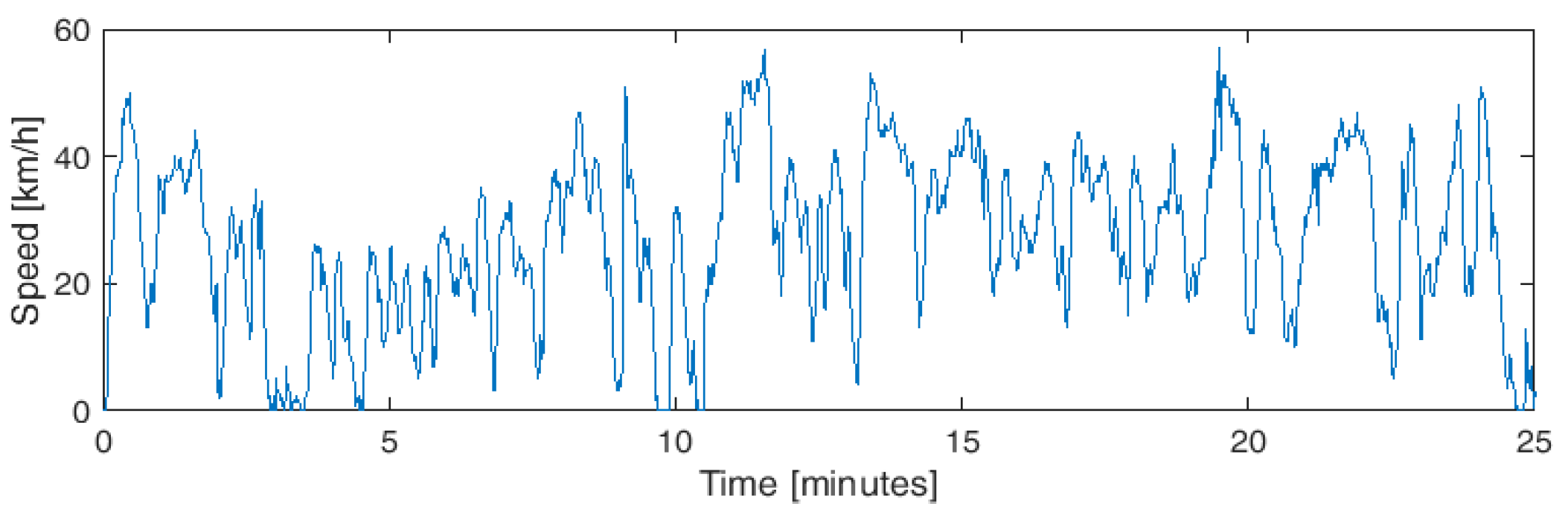
| Urban | 24 | 57 | 11.4 | 25 | - |
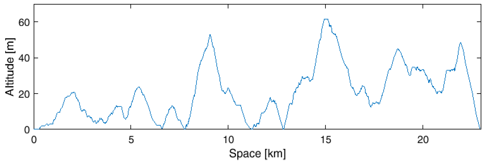
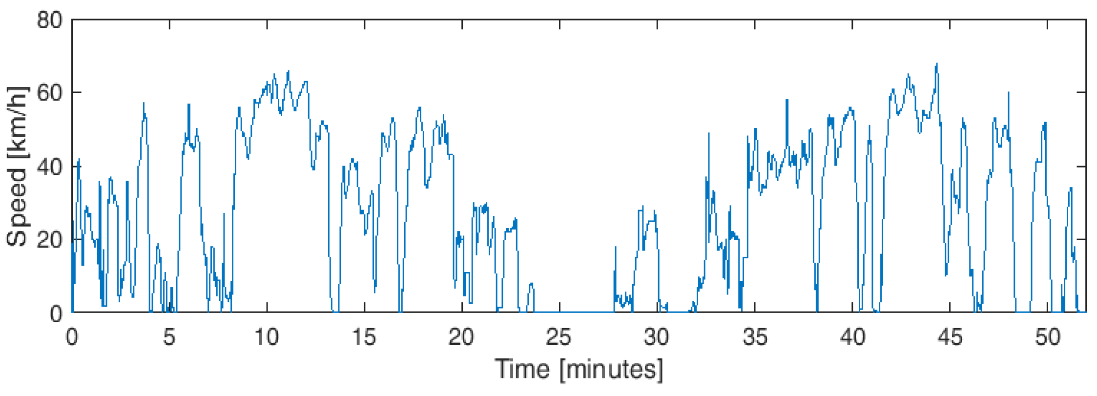
| Fast-urban | 27 | 68 | 22 | 52 | 62 |
| Extra-urban 1 | 45 | 80 | 36 | 50 | 300 |
| Mountain mission 1 | 48 | 85 | 24 | 30 | 500 |
| Extra-urban 2 | 62 | 96 | 57 | 55 | 190 |
| Mountain mission 2 | 51 | 90 | 60 | 70 | 710 |
| Highway + mountain | 87 | 125 | 480 | 330 | 1700 |
| Missions | 18 Wh | 30 Wh | 42 Wh | 54 Wh | 70 Wh | 160 Wh |
|---|---|---|---|---|---|---|
| US06 | 6 | 5 | 4 | 4 | 4 | 4 |
| UDDS | 19 | 14 | 13 | 12 | 10 | 8 |
| HWFET | 5 | 4 | 3 | 3 | 2 | 1 |
| Urban | 26 | 17 | 12 | 11 | 11 | 10 |
| Fast-urban | 21 | 16 | 16 | 15 | 12 | 10 |
| Extra-urban 1 | 35 | 26 | 18 | 14 | 11 | 5 |
| Mountain mission 1 | 12 | 7 | 7 | 6 | 6 | 5 |
| Extra-urban 2 | 39 | 35 | 30 | 28 | 21 | 11 |
| Mountain mission 2 | 29 | 23 | 16 | 14 | 11 | 5 |
| Highway + mountain | 109 | 86 | 74 | 58 | 47 | 27 |
| Missions | 18 Wh | 30 Wh | 42 Wh | 54 Wh | 70 Wh | 160 Wh |
|---|---|---|---|---|---|---|
| US06 | 7 | 7 | 6 | 5 | 4 | 3 |
| UDDS | 18 | 14 | 13 | 12 | 11 | 9 |
| HWFET | 5 | 4 | 3 | 2 | 2 | 1 |
| Urban | 21 | 20 | 18 | 14 | 14 | 10 |
| Fast-urban | 20 | 19 | 17 | 16 | 15 | 11 |
| Extra-urban 1 | 29 | 20 | 16 | 12 | 10 | 4 |
| Mountain mission 1 | 11 | 9 | 8 | 7 | 6 | 6 |
| Extra-urban 2 | 34 | 31 | 27 | 27 | 21 | 9 |
| Mountain mission 2 | 21 | 15 | 13 | 11 | 10 | 5 |
| Highway + mountain | 102 | 87 | 66 | 53 | 43 | 27 |
| Missions | 10 Wh | 15 Wh | 20 Wh | 30 Wh | 50 Wh |
|---|---|---|---|---|---|
| US06 | 0 | 0 | 0 | 0 | 0 |
| UDDS | 0 | 0 | 0 | 0 | 0 |
| HWFET | 0 | 0 | 0 | 0 | 0 |
| Urban | 2 | 1.4 | 1.2 | 1 | 0.2 |
| Fast-urban | 4.2 | 3.2 | 3.2 | 2 | 1 |
| Extra-urban 1 | 0 | 0 | 0 | 0 | 0 |
| Mountain mission 1 | 0 | 0 | 0 | 0 | 0 |
| Extra-urban 2 | 0 | 0 | 0 | 0 | 0 |
| Mountain mission 2 | 3 | 3 | 2 | 2 | 0 |
| Highway + mountain | 1 | 0 | 0 | 0 | 0 |
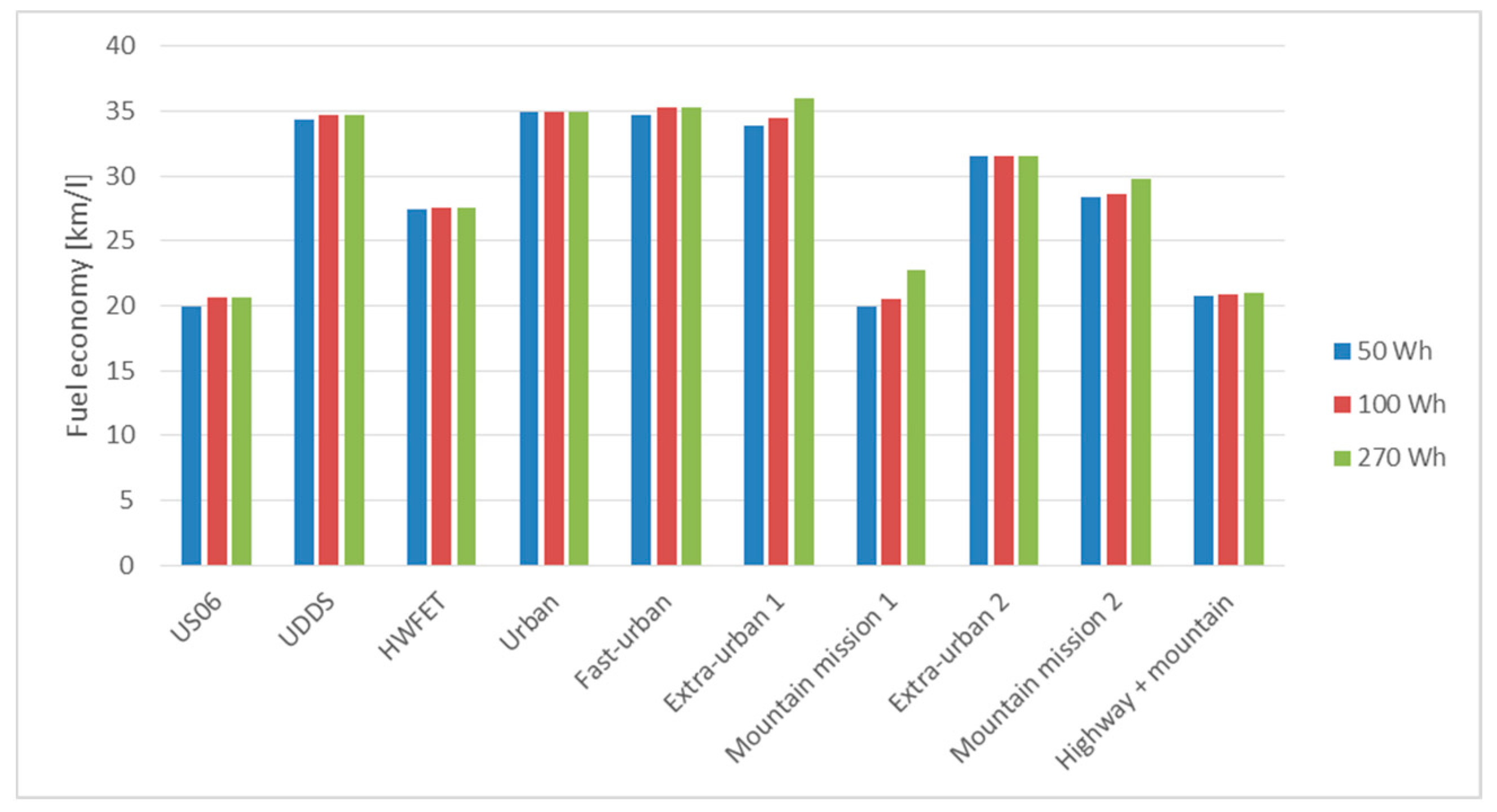
| Missions | 50 Wh | 100 Wh | 270 Wh |
|---|---|---|---|
| US06 | 3.7% | 0 | 0 |
| UDDS | 0 | 0 | 0 |
| HWFET | 1% | 0 | 0 |
| Urban | 0 | 0 | 0 |
| Fast-urban | 1.4% | 0 | 0 |
| Extra-urban 1 | 6% | 4.7% | 0 |
| Mountain mission 1 | 28.6% | 26.9% | 19% |
| Extra-urban 2 | 0 | 0 | 0 |
| Mountain mission 2 | 16.7% | 16.5% | 13% |
| Highway + mountain | 3.7% | 3.3% | 3.0% |
© 2019 by the authors. Licensee MDPI, Basel, Switzerland. This article is an open access article distributed under the terms and conditions of the Creative Commons Attribution (CC BY) license (http://creativecommons.org/licenses/by/4.0/).
Share and Cite
Passalacqua, M.; Carpita, M.; Gavin, S.; Marchesoni, M.; Repetto, M.; Vaccaro, L.; Wasterlain, S. Supercapacitor Storage Sizing Analysis for a Series Hybrid Vehicle. Energies 2019, 12, 1759. https://doi.org/10.3390/en12091759
Passalacqua M, Carpita M, Gavin S, Marchesoni M, Repetto M, Vaccaro L, Wasterlain S. Supercapacitor Storage Sizing Analysis for a Series Hybrid Vehicle. Energies. 2019; 12(9):1759. https://doi.org/10.3390/en12091759
Chicago/Turabian StylePassalacqua, Massimiliano, Mauro Carpita, Serge Gavin, Mario Marchesoni, Matteo Repetto, Luis Vaccaro, and Sébastien Wasterlain. 2019. "Supercapacitor Storage Sizing Analysis for a Series Hybrid Vehicle" Energies 12, no. 9: 1759. https://doi.org/10.3390/en12091759
APA StylePassalacqua, M., Carpita, M., Gavin, S., Marchesoni, M., Repetto, M., Vaccaro, L., & Wasterlain, S. (2019). Supercapacitor Storage Sizing Analysis for a Series Hybrid Vehicle. Energies, 12(9), 1759. https://doi.org/10.3390/en12091759