1. Introduction
Nowadays, the development of transmission system has been restricted due to various reasons such as energy, environmental, and regulatory concerns. Rapid increase in electricity demand leads the transmission lines to operate close to their maximum transfer limit. Series compensation devices have been widely used to overcome this problem. The SC lines offer many advantages such as increase in power transfer capability, enhancement of transient stability limit, improving the voltage profile and reducing power losses [
1,
2,
3]. However, with the interconnection of bulk power systems, for the line with SC device, the system impedance on the back of the line may be less than that of the traditional line. Accordingly, the fault current may be reversed during line internal fault. At this time, the differential protection of SC lines may fail to operate due to insufficient sensitivity. Consequently, SC not only influences the operational behavior of the power system, but also the performance of relay protection. It will bring a big challenge to conventional relay protection on transmission line [
4,
5].
In the existing study, there are two main schemes for SC lines protection, namely distance protection and differential protection [
6,
7,
8]. Below, firstly introduce the distance protection. The distance relays measure the positive-sequence impedance to the fault and compare it with their predefined characteristic. The presence of series capacitor in the fault loop affects reach and directionality of distance relays. The reach of distance relays may experience two major problems: (1) The reduction of series inductance of line which shifts down the locus of fault impedance in the R-X plane, and decreases the reliability of relay and (2) subsynchronous resonance which may introduce remarkable delays in the response of digital phasor estimation methods [
9]. For example, in China’s Yimin-Fengtun, Southeast Shanxi-Jingmen series-compensated transmission line projects, distance protection fails to operate. While some studies have improved the distance protection, such as [
10,
11,
12], but the trigger time of the protection is still long. Therefore, the Ultra High Voltage lines and the Extra High Voltage lines with SC device adopt differential protection as their main protection [
13].
Secondly, introduce differential protection. The fail to operate/maloperation of the differential protection on SC lines is usually ignored. Particularly, the differential protection widely used in SC lines cannot work properly due to the lack of sensitivity [
14,
15]. In Reference [
16], the conditions of the current reverse are analyzed under different fault locations and fault types for SC lines. However, it fails to put forward solutions for such a case. Reference [
17] analyzed the effect of the operation mode of circuit on current differential protection, and put forward a suitable capacitance current compensation scheme of complex four-circuit lines on the same tower. But it does not consider the problem of current reverse. In reference [
18], the influence mechanism of the current reverse on zero sequences current differential protection is discussed, and an improved scheme is provided, it is aimed at the limitation of protection sensitivity when SC lines in high transition resistance fault. However, it does not analyze the influence of fault types, fault points and power angle difference on the sensitivity of differential protection. In Reference [
19], the memory voltage and memory current are used to identify the current reverse, through analyzing the electrical characteristics of fault incepted in multi SC lines, it was found that the premise of the current reverse is the Metal Oxide Varistor (MOV for short) and AIR GAP fail to trigger. Commonly, the MOV and AIR GAP are connected in parallel to the capacitor bank or thyristor-based power-flow controller, for overvoltage protection. Thereby blocking differential protection is proposed for protecting SC lines, but this technique does not solve the problem of the failure of protection operations. It is thus necessary to further study how to improve differential protection scheme when current is reversed.
To improve the insufficient sensitivity of differential protection when the current reverse of SC lines, this paper proposes an improved scheme based on the current amplitudes and phases on both sides of the SC lines. Further, to strengthen the operation characteristics of differential protection, the triple-fold line is chosen to improve the sensitivity for internal faults. In the second section of this paper, analyzes the causes of the current reverse. In the third section, we study the effects of SC degree, power angle difference, transition resistance, fault types, system operation mode, and fault points on the operation characteristics of differential protection. In addition, provide a new scheme in the fourth section to address the fail to operate of the protection functions for SC lines. Finally, the fifth section and the sixth section verify the reliability of the proposed method through the PSCAD/EMTDC simulation and the power system dynamic physics simulation.
2. Current Reverse Reason Analysis
Compensation devices in the transmission line include TCSC (thyristor-controlled series compensation) and FSC (Fixed Series Compensation). The large short-circuit current in the SC will lead to the fast action of the MOV and AIR GAP protection system (within 1 ms [
20]). Whereas, when grounded with high transition resistance, the short-circuit current is very small, the MOV and the AIR GAP may not lead to a bypass, hence the capacitor remains in service. The current reverse in SC lines will occur in terms of large system interconnection. The working condition of relay protection will be in a more serious state. If differential protection fails to operate at this time, it will have adverse effects on the power system. Therefore, it is necessary to analyze the causes of the current reverse in detail.
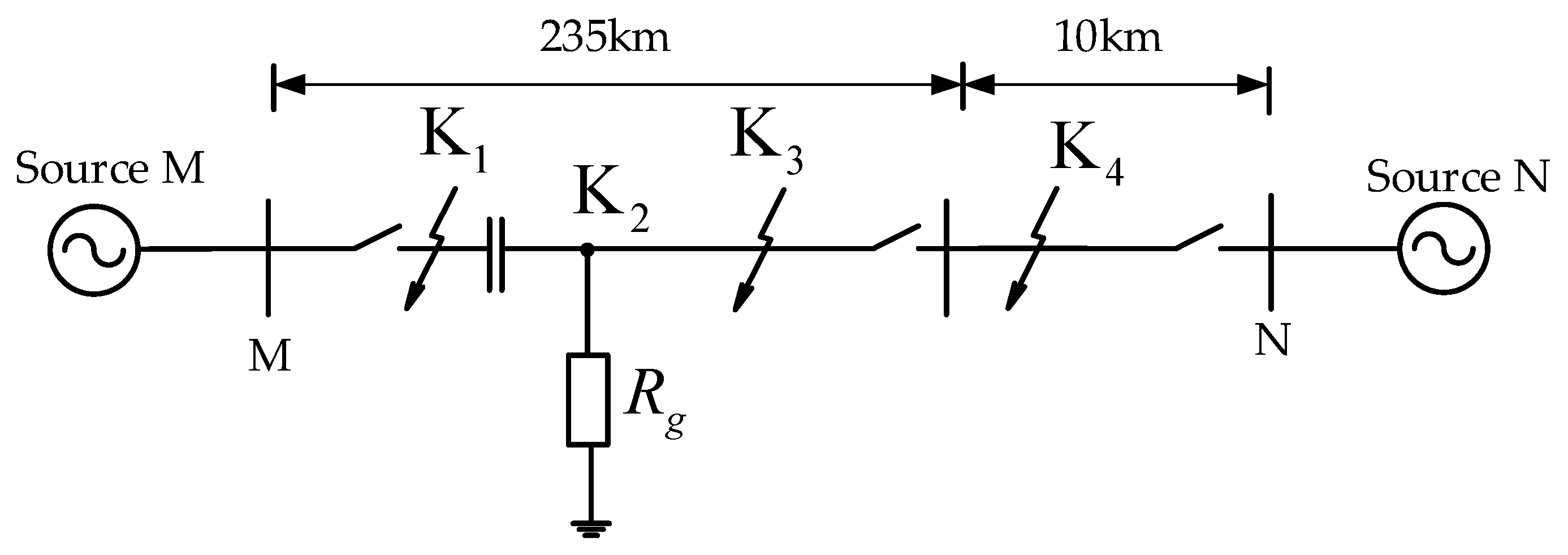
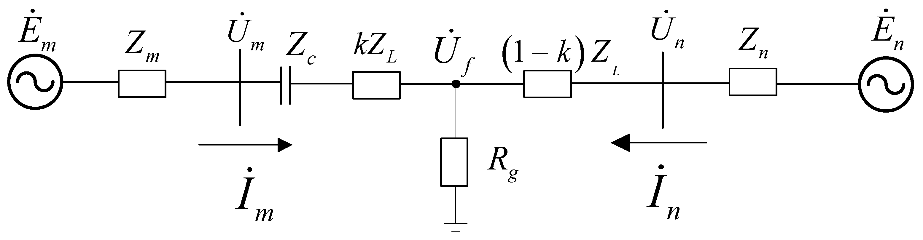
A simple two-terminal system is used to exemplify the principle. For high SC lines under internal fault, the equivalent model of the single-loop system is demonstrated in
Figure 1.
The following parameters are considered while deducing the expressions of fault parameters.
Where, and are voltages of the source at sending end and receiving the end of the transmission line, respectively.
, , , are the voltage and current phasor measured by the protection at two ends, respectively.
is the fault voltage.
Zm and are used to denote equivalent impedance of power source at sending end and receiving end.
is the entire line impedance.
is line impedance from sending end to the point F.
is line impedance from receiving end to the fault point F.
Zc is the impedance offered by series capacitor.
2.1. Symmetric Short
The current at M side is shown below when a symmetric short circuit occurs at point F.
Under the interconnection of the bulk system, will be smaller. When point F closes to bus M, in other words the value of k is relatively small, hence will be less than . Consequently, the current will be reversed.
In this case, the equivalent impedance at the left side of point F is capacitive. Namely,
is leading up to
, or in other words current is reversed. The voltage at both ends of the SC device under the fault is shown below.
is the voltage amplitude at both ends of SC device. In practical engineering, when
is greater than the outlet fixed value, the MOV and AIR GAP protection system operate, thus the capacitor can be bypassed immediately. As a result, current reverse will only appear within 1 ms and then recover [
20]. It can be approximated that the current reverse does not occur.
2.2. Single Phase Grounding Fault
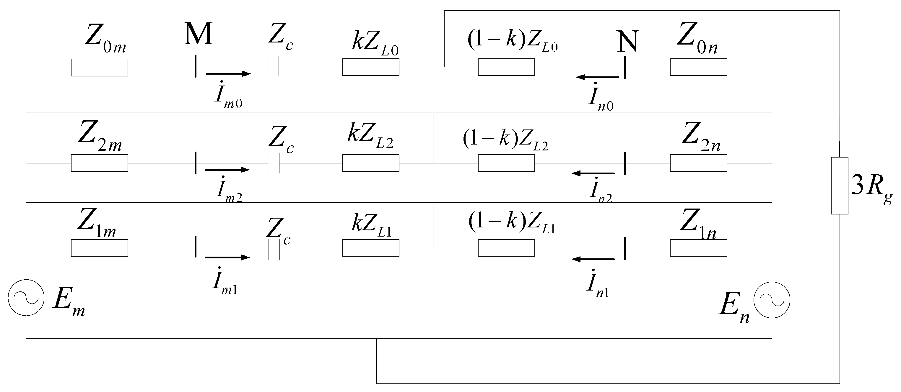
Single-phase ground faults account for more than 90% of asymmetric faults. Therefore, this section focuses on whether current reverse occurs in single-phase ground faults. Assume that the positive sequence impedance is equal to the negative sequence impedance in the system, when an asymmetric fault occurs at point F. The single-phase grounding composite sequence network diagram after the fault is shown in
Figure 2, subscripts 0, 1 and 2 represent zero sequence components, positive sequence components, and negative sequence components, respectively.
The positive sequence fault currents of M and N sides can be obtained from
Figure 2:
In Equation (3), when
is much less than
,
will lead
. But whether that current is capacitive or not also depends on the fault current of opposite side
. Supposing that the system amplitude values are equal on both ends, that is,
(
is the power angle difference on both sides of the system). Through Equations (3)–(5) to eliminate
, the positive sequence fault current for M side can be acquired.
where,
. From the analysis above, if
is much less than
, subsequently the positive sequence current calculated in Equation (6) will reverse. At this time, the amplitude and phase angle of the positive sequence current are affected by power angle difference, back impedance of system and transition resistance.
For the zero-sequence network, specific analysis is carried out in reference [
18]. It is easy to find that the current would reverse if
is much less than
(Similar analysis can be performed for negative-sequence circuit).
The fault current of M side is shown in Equation (7) through calculating with positive sequence, negative sequence and zero sequence fault current. In this case, if
is much less than
,
and
will be reversed, so
will definitely be reversed according to Equation (7). Therefore, when an internal fault occurs in a high SC degree transmission lines, current may be reversed, which brings a risk of operation failure of the line differential protection.
It is observed from Equations (6) and (7) that fault current may be low if transition resistance is too large. In this case, the MOV and AIR GAP protection system cannot operate, SC will be equal as a capacitor. Consistent with the analysis at the beginning of this section.
In summary, the following conclusions can be drawn:
(1) When three-phase symmetrical fault occurs, there is no current reverse, which has no effect on differential protection.
(2) When an asymmetry internal fault occurs, the short circuit current is small due to the presence of the transition resistor, and the MOV and AIR GAP protection system may not operate. Under this premise, if is much less than is satisfied, the current is reversed. For interconnected large power systems, is very small. If the fault point is close to SC equipment, that is, K is very small, then much less than is satisfied, current reverse occurs at this time.
(3) Moreover, the amplitude and phase of fault current are affected by transition resistance, power angle and the equivalent impedance.
3. The Influence Factors of Current Differential Protection and Its Analysis
3.1. Factors of Differential Protection Fail to Operate
According to the previous section, SC lines are potential to have current reverse in internal faults. At the same time fault current is affected by a variety of reasons, such as the degree of compensation, the equivalent impedance, and the power angle of the system, fault types (category and location), transition resistance and so on. Current differential protection is the main protection of SC lines, and its differential current is calculated as the module value of the sum of the fault current at both ends of the protection system. While the fault current of one end reverses, the protection is very likely to fail to operate due to the lack of sensitivity.
In order to analyze the characteristic of current differential protection when the current is reversed, this paper judges whether the differential protection is operated or not according to the change of sensitivity. For the convenience of theoretical analysis, the general criterion of current differential protection is shown in Equation (8).
where,
is the line differential current.
is the restraining current.
is the minimum operating threshold value.
is the restraining ratio coefficient.
is a coefficient selected according to the calculation of sensitivity.
while assuming the amplitude values of source voltage at two ends are equal.
is power angles difference of system.
When internal fault occurs, both and are positive values, the numerator is much larger than the denominator, and Ksen is very large.
When the system is in normal operation or external fault occurs, is positive, is negative, is approximately 0, is small. Therefore, with the value of , it is easy to distinguish whether it is internal fault or external fault.
Taking asymmetric ground fault as an example and combining Equations (3)–(5), the sensitivity coefficient of positive sequence is obtained in Equation (9).
For the zero-sequence circuit, the sensitivity coefficient has been calculated in reference [
18] (negative-sequence is similar), it is shown in Equation (10).
From Equation (10), it can be obtained that the sensitivity is decreased with the increases of the degree of compensation and the value of K. However, Equation (9) is more complicated, and the trend of sensitivity cannot be directly calculated, further classification analysis is as follows.
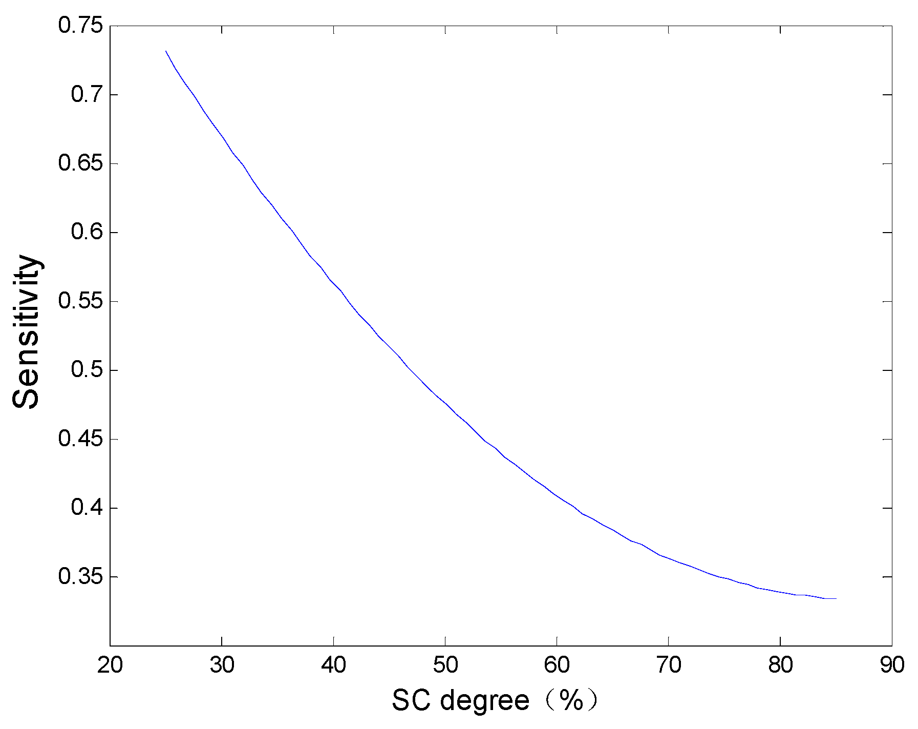
3.2. The Effects of Series Compensated Degree
If SC degree is greater than 50%, current reverse will occur during internal faults [
21]. The viewpoint also has been demonstrated in the first quarter of this paper. As the SC degree increases, coupled with the interconnection of the power system, the system impedance in the back of the line becomes smaller, the fault point is relatively close to protection, and hence the probability of current reverse will increase significantly. For Equation (9), when the power angle difference and the transition resistance (setting to 0) are constant, assuming the values of
and
are equal, it can be simplified as Equation (11).
where,
,
,
. The coefficient of m is a constant. It also can be found from Equation (11) that sensitivity decreases with the increase in SC degree.
However, a decrease in sensitivity does not necessarily mean that protection mis-trip will occur. It needs to take system equivalent impedance and short circuit impedance into consideration. Taking Equation (11) as an example, in the transmission line without SC device,
is usually greater than
. So, the sensitivity coefficient is greater than one, which indicates it makes no difference on operating characteristics of protection. But with the development of large SC lines, combined with the powerful interconnection of the back system, in this context, the capacitance
will increase and system inductance
will decrease. Therefore
is greater than
is no longer necessary. It is the tipping point for current reverse when
equals to
and the sensitivity of protection will be lower while
is much less than
. The variation relation between sensitivity and SC degree is reflected in
Figure 3. If SC degree is more than 50%, the sensitivity of protection will be lower than 0.45. Under this circumstance, differential protection is unable to operate due to lack of sensitivity during the internal fault.
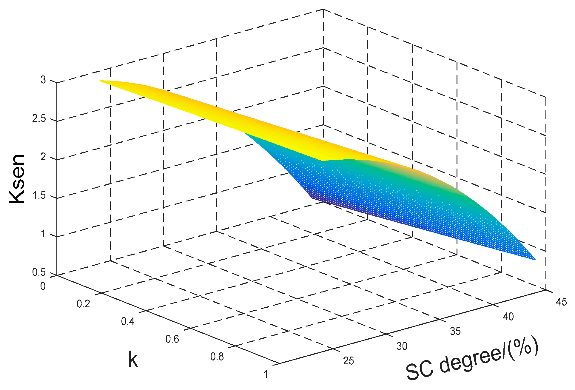
3.3. The Effects of Compositing Series Compensation and Fault Points
If the short-circuit current is too small to trigger the MOV and AIR GAP protection system. The differential protection will not work properly. Given that power angle difference and transition resistance are fixed, Equation (9) can be simplified to Equation (12).
Figure 4 shows the protection sensitivity under different SC degree and
k.
K is the ratio between the distance from the fault points to the left bus and the total length of the line. When the system SC degree is small,
Ksen increases with the increase in k, which does not affect the operation of relays. However, when the SC degree is large,
Ksen value decreases, then relays may fail to operate.
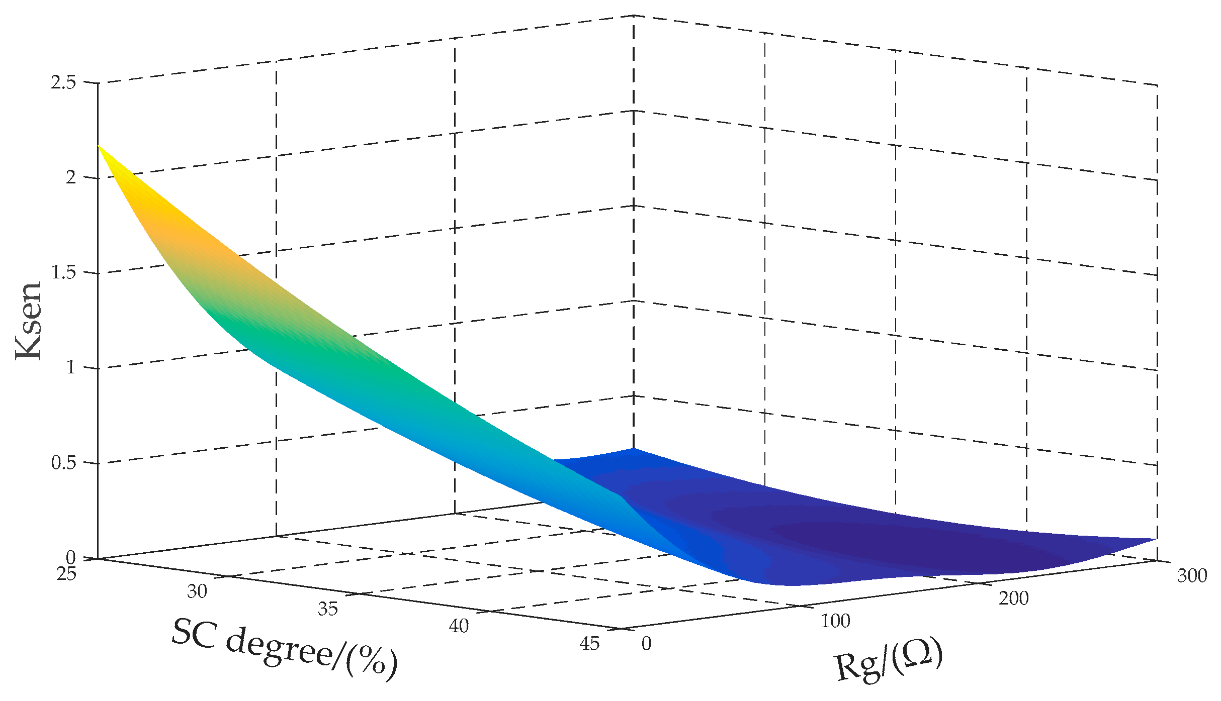
3.4. The Effects of Compositing Series Compensated Degrees and Transition Resistance
Based on the foregoing analysis, only when the fault current exceeds the thermal limit of MOV and bypasses the operation, can the protection operate accurately. However, the fault with high transition resistance will not cause bypass operation because of the small fault current. Even if the compensation degree is not too high, the sensitivity will be greatly reduced due to the adverse effects of capacitance and resistance. Supposing the amplitude values of source voltage at two ends are equal and power angle difference is a constant, that is .
Equation (9) can be further simplified as Equation (13).
Figure 5 shows the protection sensitivity under different SC degree and
Rg. From
Figure 5, when the transition resistance is small, SC plays a major role in reducing the sensitivity of differential protection, and only large series compensation will have lower sensitivity. If the degree of series compensation is between 25% and 45%, the differential protection will operate. However, when the transition resistance exceeds 200 Ω, transition resistance plays a major role in reducing sensitivity of differential protection. The sensitivity of the protection shown in the
Figure 5 is less than 0.5, and the differential protection will fail to operate because of the lack of sensitivity in internal fault of the series compensation lines.
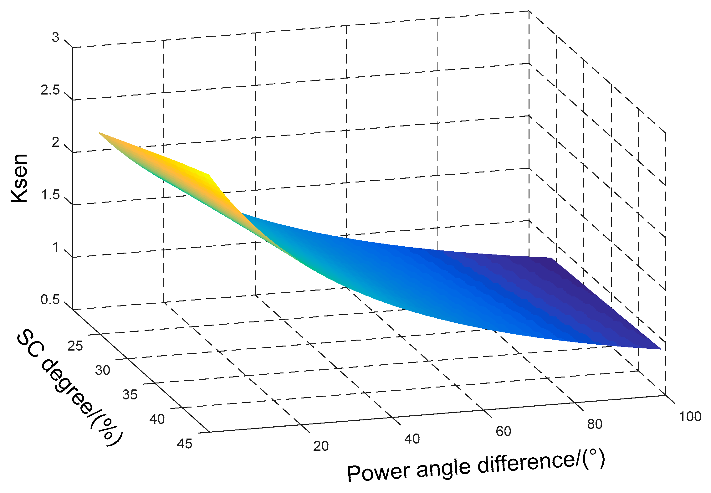
3.5. The Effects of Compositing Series Compensated Degrees and Power Angle Difference
Previously analysis is under the assumption of invariable power angle difference. In fact, the power angle is changeable with system operation. It also can be inferred from Equation (9) that the angle difference has effect on the sensitivity of differential protection. If there is a metallic grounding fault on the SC lines, Equation (9) can be transformed to Equation (14).
Figure 6 shows the protection sensitivity under different SC degree and power angle difference. As seen from
Figure 6, when the power angle difference is small, the protection sensitivity is high. However, the sensitivity of protection decreases with the increase in power angle and SC degree, and the protection may even fail to operate due to the lack of sensitivity.
4. The Improved Scheme
The risk of current reverse exists in the SC lines during the internal fault, which can lead to the decrease of sensitivity or even the failure of differential protection. Even for the same fault type, protection will have different performance due to different restraining current or restraining coefficient. The restraining current of traditional differential protection is based on the sum of phasor on both sides of the lines. However, it is constrained as the current reverse occurs during internal fault on SC lines, and this technique is also not tested for fault on capacitor outlet, fault on far-end, and high resistance fault. Therefore, a new nonlinear restraining protection criterion is constructed in this paper by studying the scalar product restraining characteristics and using the amplitude-phase relation of the current on both sides of the SC lines. In a way, the new differential protection scheme has improved the sensitivity for internal fault and the reliability of restraining characteristics for external fault. Specifically, this paper improves the conventional differential protection from two aspects.
On the one hand, the conventional restraining current is improved to , is the angle between and , and differential current calculation is changeless, still taking the value of . The amplitude of the conventional restraining characteristics is combined with the phase characteristics of the circuit, while calculating the restraining current. The features, including the phase of fault current, tend to be the same, and there is no current reverse in internal fault, which is contrary to the normal operation or external fault. Similar to the principle of scalar product restraining, in this paper, multiplying the conventional restrain amount by the value of , then . The original restraining effect during external faults is kept in this restraining characteristic, while restriction is reduced sharply to improve the sensitivity of the protection at internal faults. In addition, even fault current reverses, the phase angle is not around 180°, but around 235°. At this point, is set to make the denominator of smaller, thus making larger. Therefore, for the improved criterion, whether the current is reversed or not, the sensitivity of differential protection can be guaranteed.
On the other hand, by improving the restraining coefficient, the action zone is formed from a conventional double-fold line to a triple-fold line. For the protection scheme proposed in this paper, whether the protection acts or not depends on whether the resulting points (Id, Ir) falls in the action zone in the Id-Ir coordinate plane. When the current is reversed, in the Id-Ir coordinate plane, the resulting points (Id, Ir) may fall into the restraining zone of the conventional double-line scheme. At this point, the relay will misjudge that the system has an external fault and does not operate.
Compared with the conventional protection scheme, the improved protection scheme has two advantages. Firstly, the improvement of the restraining current makes the resulting points on the Id-Ir coordinate plane is as close as possible to the Y-axis. Since the sensitivity is defined as , the closer the resulting points is to the Y axis, the higher the sensitivity of the protection scheme. Secondly, the improvement of the restraining coefficient makes the action zone larger, which can better accommodate the resulting points when the current is reversed. The new protection scheme can not only ensure the protection sensitivity in the internal fault with current reverse, but also ensure that the protection does not operate in external fault.
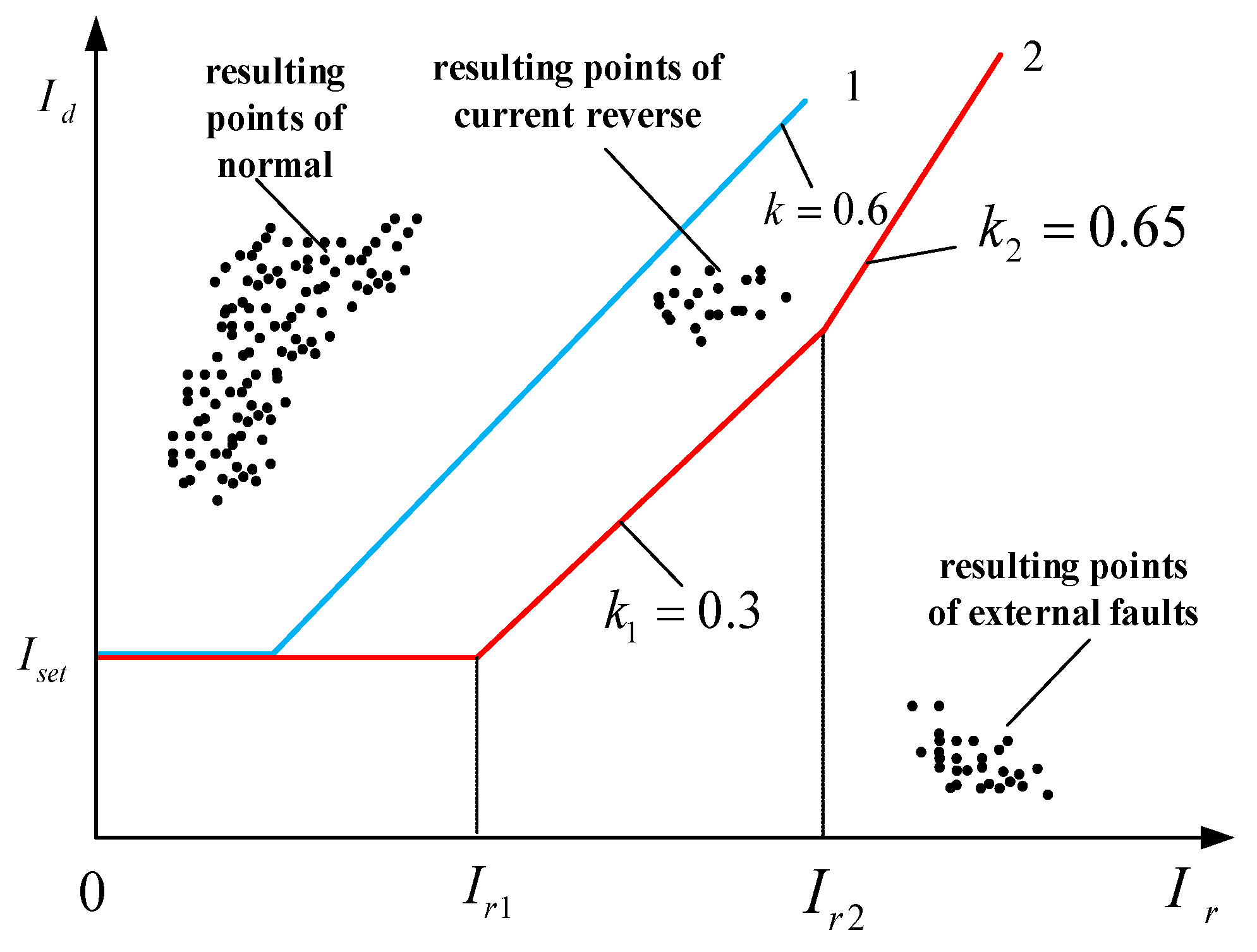
Operation criteria of the Cartesian Plan are as follows.
, and are the restraining coefficients and set based on the general engineering experience. ranges from 0.2 to 0.5, varies from 0.6 to 0.9. In this research, takes 0.3 to guarantee the protection sensitivity in internal fault, takes 0.65 to avoid maloperation of protection in external fault. Ir1 is the restraining current of the first inflection point of the triple-fold line differential protection; Ir2 is the restraining current of the second inflection point of the triple-fold line differential protection.
By Equation (15), the qualitative analysis of the conventional double-fold line (blue) and the improved triple-fold line (red) is shown in
Figure 7. Above the fold line is the action zone, below the fold line is the restraining zone.
As illustrated in
Figure 7 that either in external fault or normal conditions, the resulting points are inside the restraining area. In internal faults, the traditional protection based on double-fold line may maloperation when the fault current is reversed, while the improved scheme based on triple-fold line shows accurate operation in the same situation.
5. PSCAD Simulations and Results
A two-terminal 500 kV, 50 Hz system as shown in
Figure 8 was used to verify the behavior of the proposed current differential protection system. It is simulated by EMTDC/PSCAD software to obtain the sensitivity data, which is used for protection performance evaluation. Under the same conditions, to compare the sensitivity of improved scheme with conventional scheme. This study focused on influencing factors, including different SC degree, fault types, power angle difference, fault points and transition resistance.
TCSC is 50 km from Bus M.
K1 point is on the left side of the TCSC, 10 km from the TCSC.
K2 point is on the right of the TCSC, 10 km from the TCSC.
K3 point is 150 km away from TCSC.
K4 point is located outside the protected area, 3 km from the Bus N.
, are the positive sequence impedance of each source.
, are the zero-sequence impedance of each source.
is equal to the positive sequence impedance of the basic circuit.
is equal to the zero-sequence impedance of the basic circuit.
5.1. The Effect of Transition Resistance
Table 1 shows the protection sensitivity under different series compensation and grounding resistances. Setting
Rg = 0, 50, 150, 300 at K2 point. The sensitivity decreases with the increase in the transition resistance and the SC degree. The sensitivity of the traditional scheme decreases greatly with the increase in the SC degree, even less than 0.4, when the transition resistance is small (no more than 50 Ω). As to the improved scheme, the sensitivity is more than 1. When the transition resistance is large (more than 150 Ω), the sensitivity of the two schemes decreases slightly with the increase in SC degree, both are less than 1. However, the improved restraining current is always far less than the traditional one. At this time, for high resistance grounding fault, the resulting points is placed above the characteristic curve whose ratio is 0.3. It means the sensitivity provided by improved scheme is enough. In comparison, the conventional protection failed to operate, but the improved one operated reliably.
5.2. The Effect of Power Angle
Table 2 shows the protection sensitivity under different series compensation and power angle. When the power angle difference is small (less than 50°), the sensitivity of the improved scheme is greater than 1 regardless of the SC degree, while the sensitivity of the conventional scheme is less than 1. With the increase in power angle and SC degree, for example, when the power angle difference is greater than 70°, the conventional protection sensitivity will be lower than 0.6. Therefore, maloperation will occur due to the lack of sensitivity. For the improved scheme, the resulting points are placed above the characteristic curve whose ratio is 0.65. The ratio is far less than the result, thus the differential protection can operate accurately.
5.3. The Effect of Fault Types
Table 3 shows the protection sensitivity under different series compensation and grounding resistances. When different faults on SC lines occur under same conditions, the sensitivity is very different. Particularly, the sensitivity of interphase fault is obviously higher than that of grounding fault. Combining the adverse effect of high SC degree and high grounding resistance, in cases like this, SC degree is more than 50% and transition resistance is over 150 Ω, the conventional protection fails to trip for the sensitivity is too low when there is a two phases or single phase grounding fault. While the sensitivity of the improved scheme is not too high, it is still greater than 0.3. The resulting points are placed above the characteristic curve whose ratio is 0.3. Therefore, differential protection can cut off the fault.
5.4. The Effect of Fault Points
Table 4 shows the protection sensitivity under different series compensation and fault points. According to
Table 4, when the system has external fault (K4), the Ksen of the two protection schemes is less than 0.15. The sensitivities are all below the characteristic slope of curve 0.65 in the
Figure 7. Thus, no trip will be issued for this condition. When the system has internal fault (K1, K2, K3), the Ksen calculated by the improved protection scheme is twice as large as that of the conventional protection scheme. Even if there is a severe short circuit at the outlet of the SC (K2), Ksen calculated by the improved scheme is not less than 0.8.
5.5. Contrast Before and After Improvement
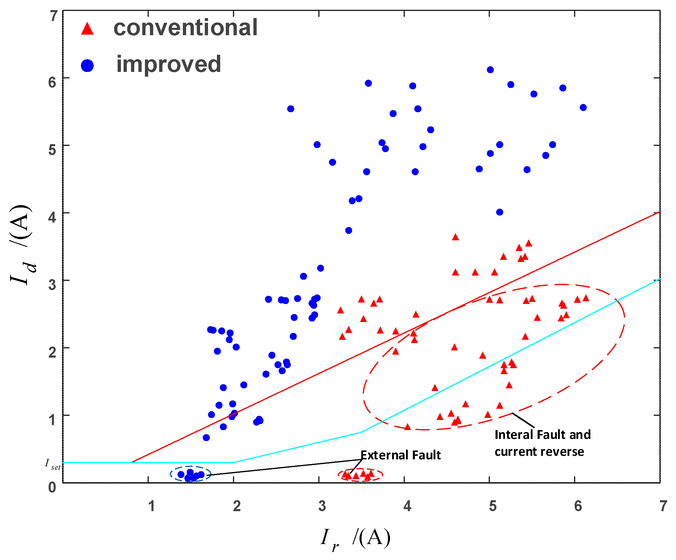
Figure 9 is the
Id-Ir diagram drawn based on the simulation. The red dots represent the conventional scheme and the blue dots represent the improved scheme. When external fault occurs in the system, both the conventional scheme and the improved scheme are in the restraining zone, and the protection does not operate. When internal fault occurs in the system, the conventional protection scheme may fail to operate due to the reverse current. With the improved protection scheme, the improved restraining current makes the resulting points (
Id,
Ir) on the
Id-Ir coordinate plane is closer to the Y-axis, that is the sensitivity is greatly improved. However, there are still few points outside the double-fold line. Therefore, the combination of the improved restraining current and the triple-fold line can ensure the reliability of the protection device.
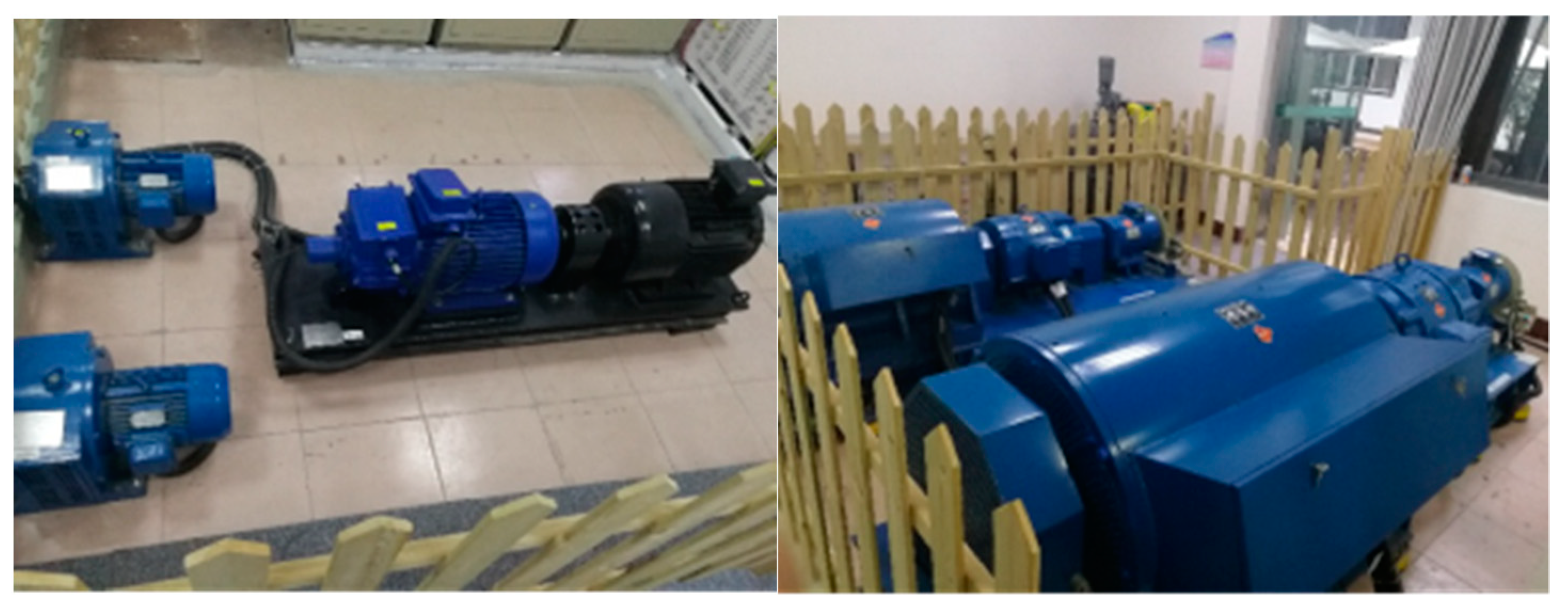
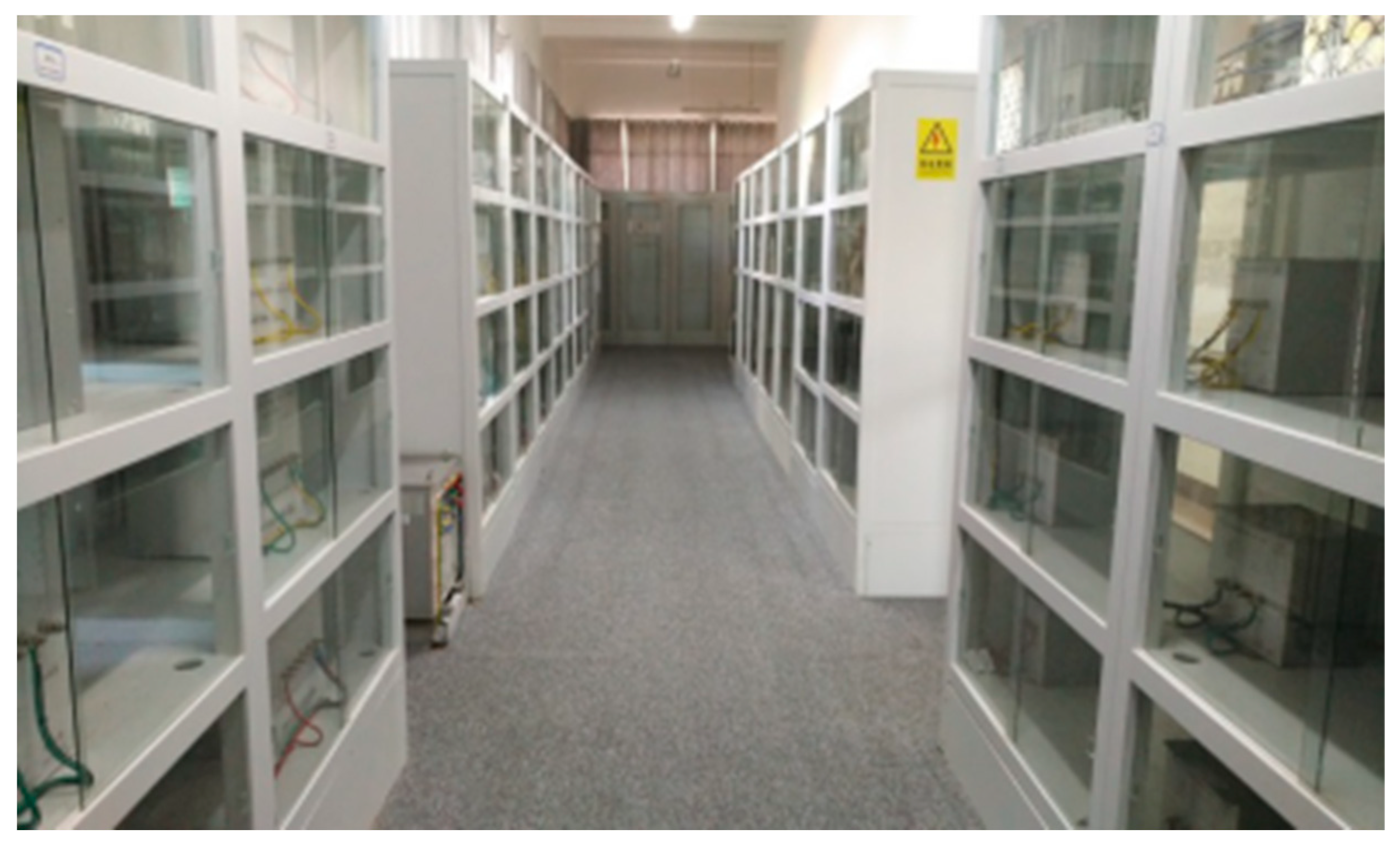
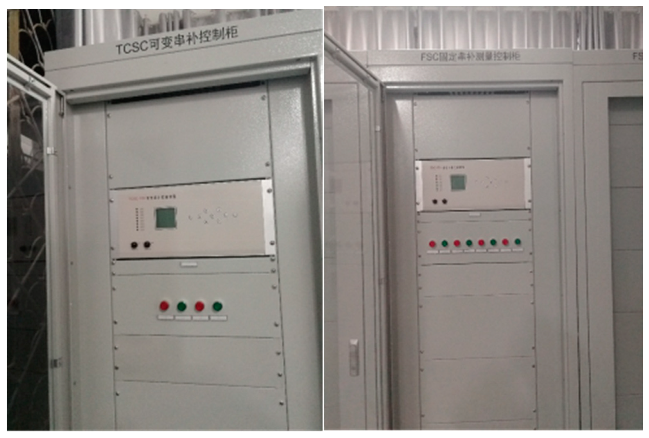
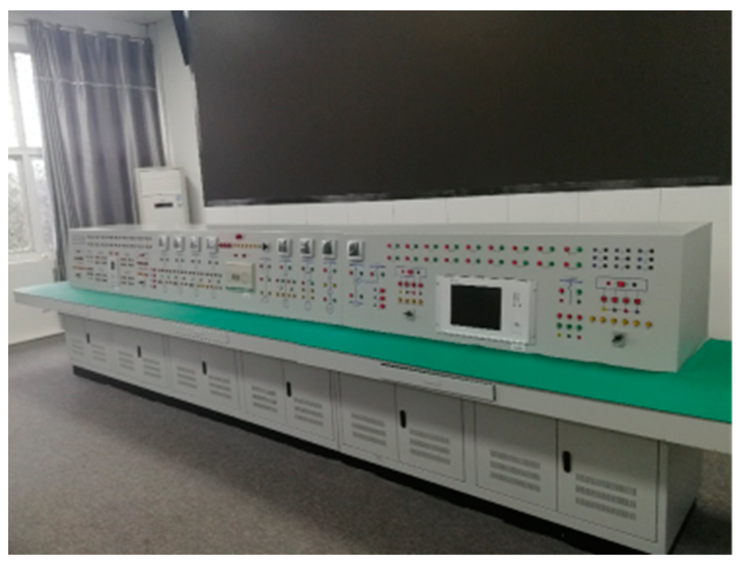
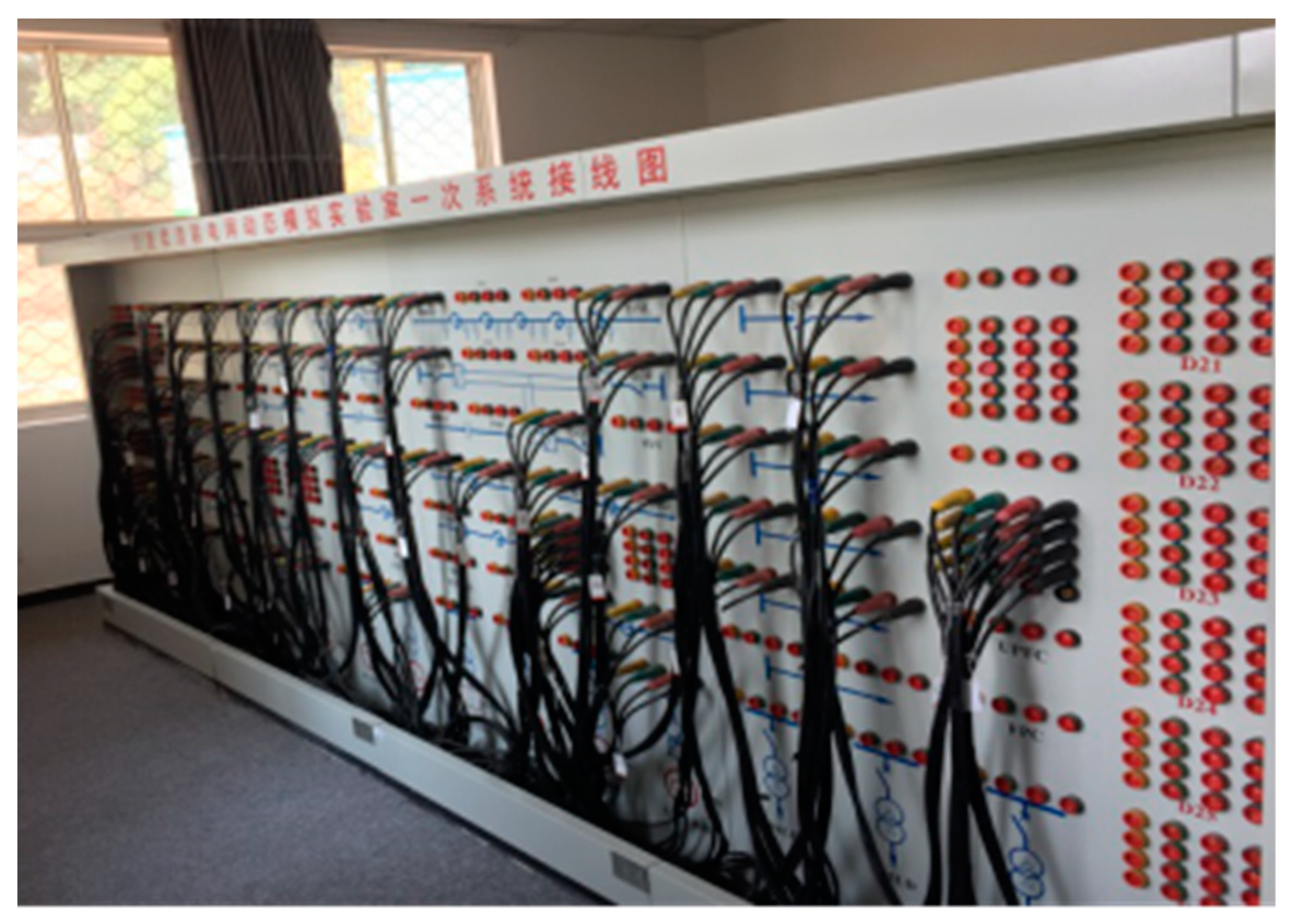
6. Dynamic Physical Simulation
Power system dynamic physics simulation is established by using physical components with the same physical properties and per-unit values as the actual power system. Generally speaking, it is a simulation of the actual power system. The dynamic model simulation is carried out in our school’s Power System Dynamic Physics Laboratory. The dynamic physical model mainly uses small capacity synchronous generators, transformers, transmission lines, motor loads to form the actual power system network. At the same time, it can realize fault simulation, data measurement, relay protection, and other functions. The basic operating principle of the experiment agrees with the dynamic model experiment mentioned in reference [
22,
23,
24,
25]. Photographs of some dynamic physical simulation devices are shown in
Appendix A.
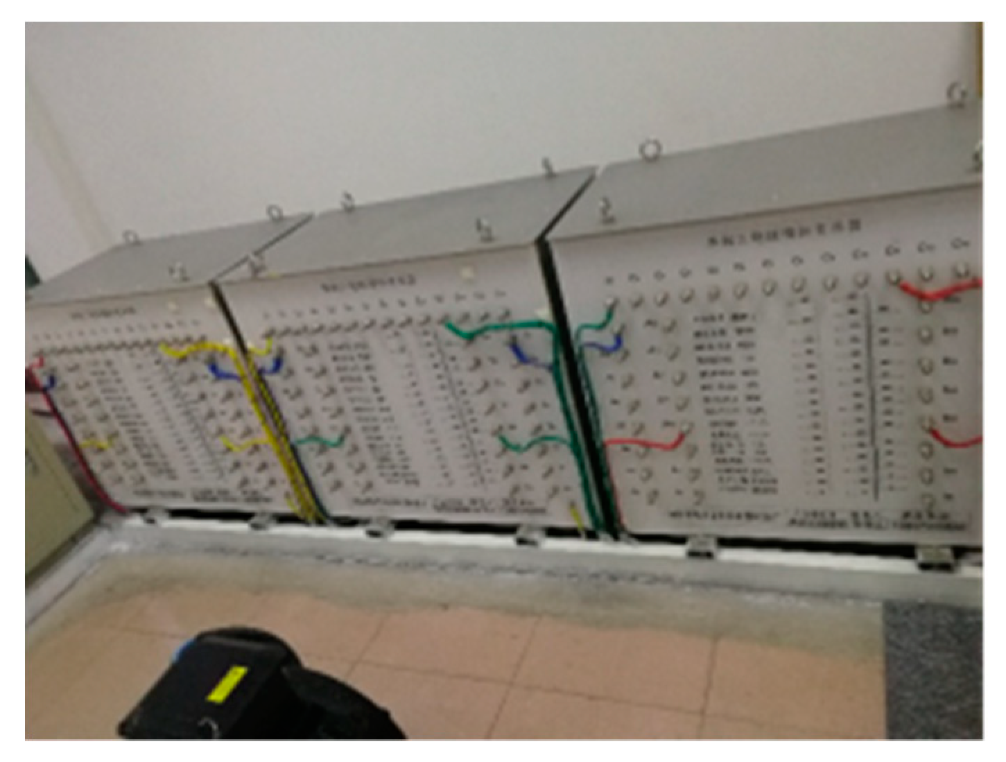
The specific simulation process is as follows:
(1) Construct the physical model of the power system in the text and record the waveform of its operation using a fault disturbance recorder.
Fault disturbance recorder can automatically and accurately record the changes of various electrical quantities before and after faults when system faults occur. Through the analysis and comparison of these electrical quantities, it plays an important role in analyzing and dealing with accidents, judging the correct action of protection and guaranteeing the safe operation of power system.
(2) Programming the proposed protection scheme and conventional protection scheme in MATLAB.
(3) Using the MATLAB program mentioned in step (2) to process data, then judge whether the resulting points (Id, Ir) falls into the action area.
(4) Analyzing relay operation under various circumstances to verify the reliability of the proposed scheme.
6.1. Building the Dynamic Physical Simulation Model
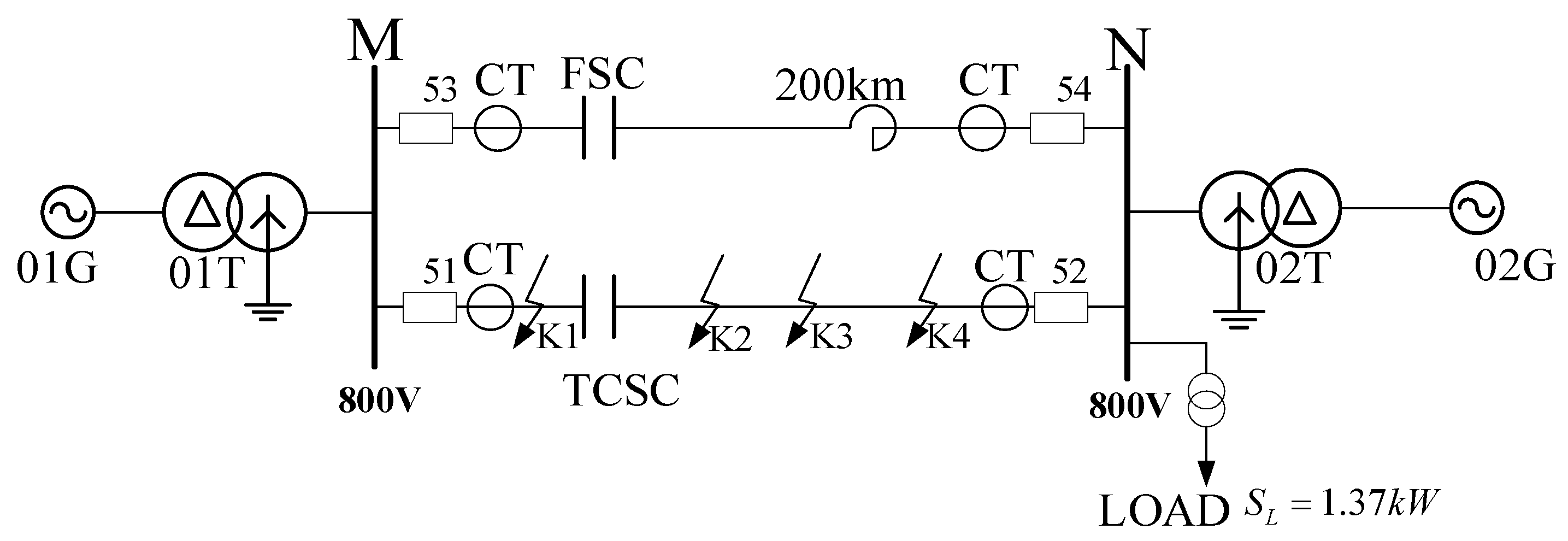
The power system dynamic physics simulation model is shown in
Figure 10. Using 800 V to simulate 500 kV in the laboratory. The full length of the double-circuit line MN is 200 km. One of the lines is equipped with FSC, and the series compensation degree is 25%. Another line is equipped with TCSC, which can be adjusted from 25% to 75%. Where,
,
, LC circuit resonant frequency is
, resonant angle is 141.70°.
TCSC is 50 km from Bus M.
K1 point is on the left side of the TCSC, 10 km from the TCSC.
K2 point is on the right of the TCSC, 10 km from the TCSC.
K3 point is 80 km away from TCSC.
K4 point is 120 km away from TCSC.
The conversion of the per unit values of all the above parameters is based on the selection of a base voltage of 800 V and a base current of 20 A. The data in
Table 5 are the original values set by the equipment manufacturer.
6.2. Analysis of Power System Dynamic Physics Simulation
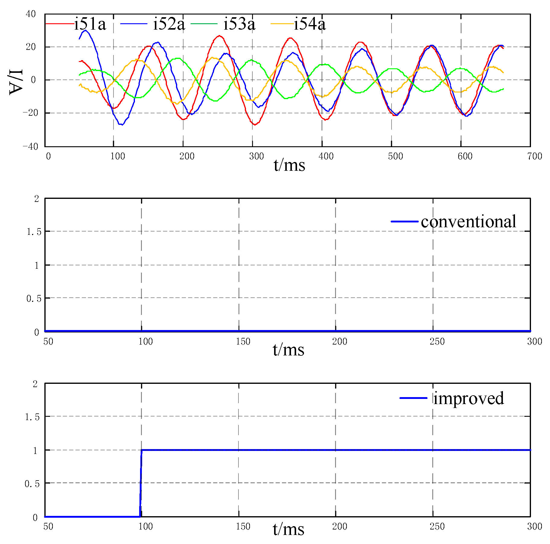
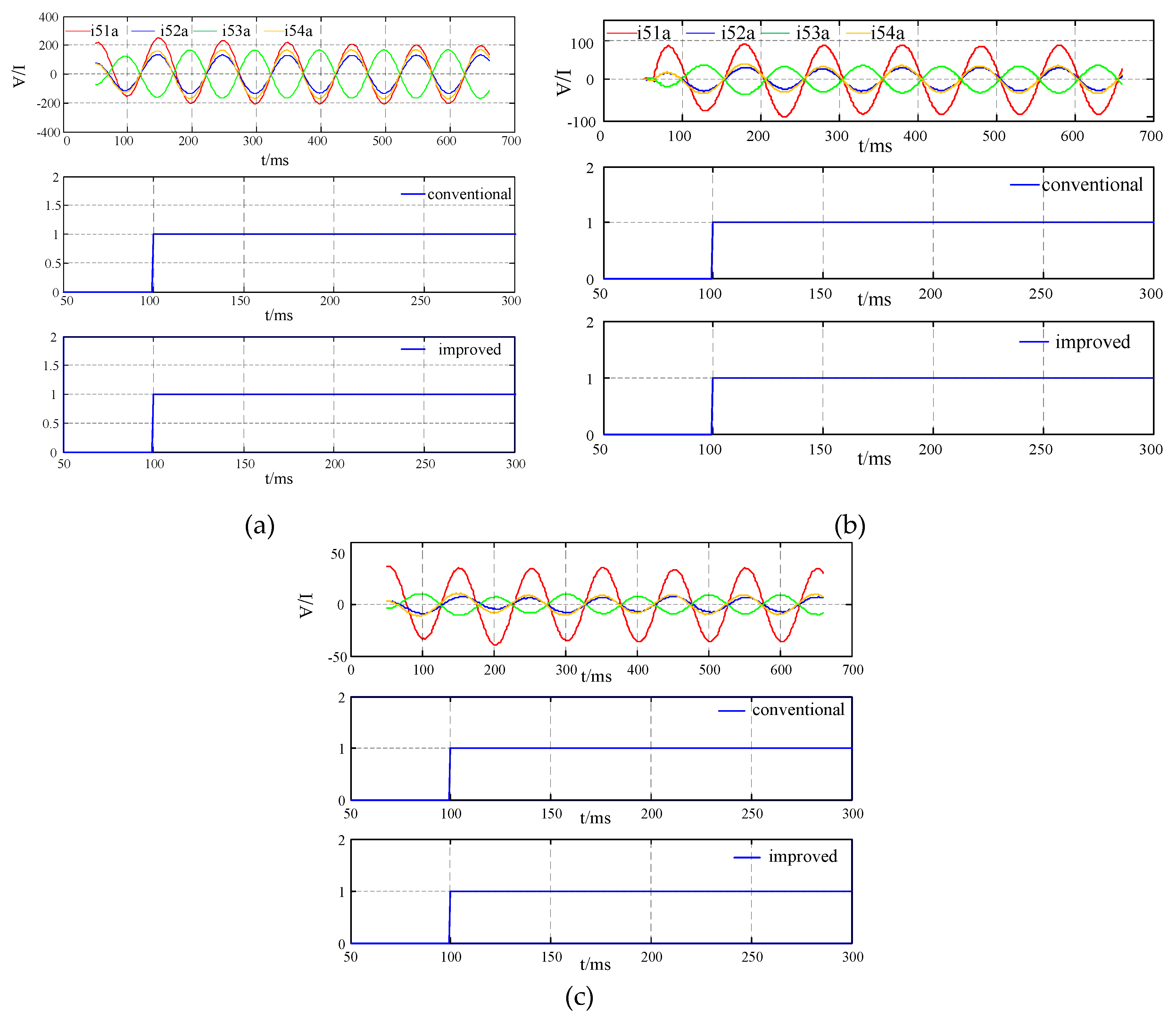
, , and are the current flowing through circuit breaker 51, 52, 53, 54, respectively (instantaneous value). 0 and 1 are Boolean quantity. 0 means the relay does not work, 1 means the relay action.
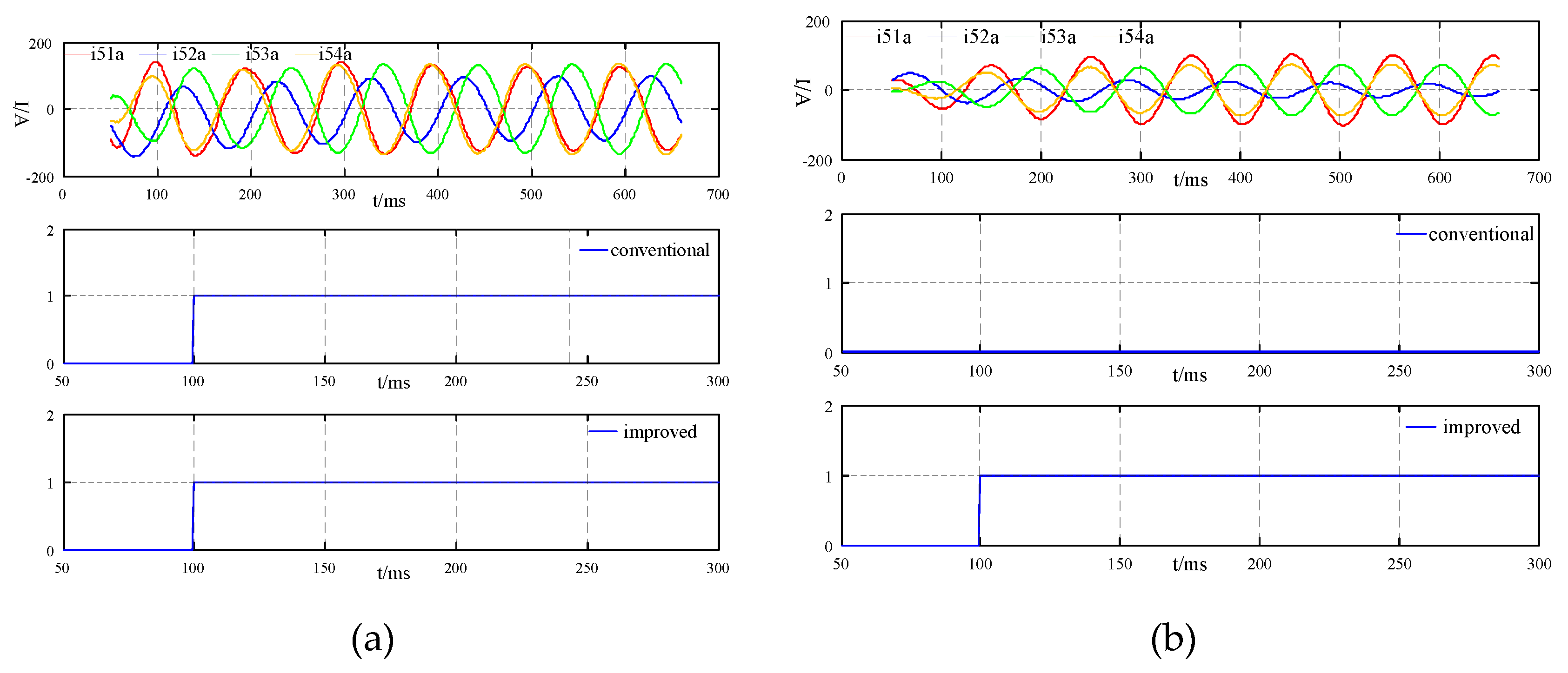
(1) The dynamic physical results at K1 are shown below.
According to the comparison and analysis in
Figure 11, when the fault occurs on the left side of the SC, the current will not reverse under three-phase short-circuit fault and single-phase high transition resistance fault. At this point, both the conventional protection and improved protection can operate correctly.
(2) The dynamic physical results at K2 are as follows.
It can be obtained from
Figure 12 that there is a current reverse when the outlet of the SC shorted. As can be observed from
Figure 12a, when the three-phase short circuit occurred, the fault currents
and
have opposite phases, but the amplitude is large, which can trigger the MOV and AIR GAP protection system action, and both the traditional and the improved differential protection can operate correctly. In
Figure 12b, when single-phase grounding fault occurred, due to the influence of transition resistance, the magnitude of fault current is small and the MOV and AIR GAP protection system protection action cannot be triggered. Therefore, the current reverse will make the conventional current differential protection fail to operate. While the improved current differential protection can effectively overcome the influence of reverse current and avoid protection rejection.
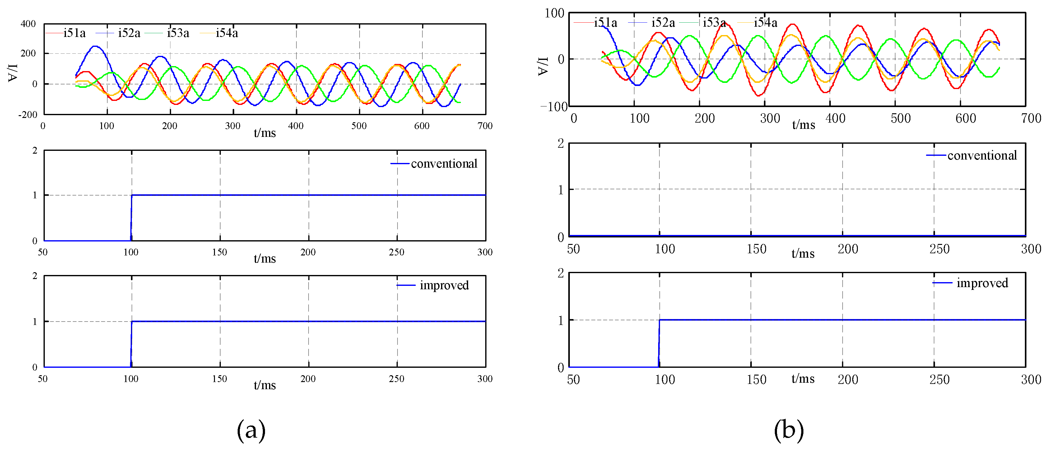
(3) The dynamic physical results at K3 are shown below.
It can be seen from
Figure 13 that there is a current reverse when the outlet of the series compensation capacitor shorted. As can be observed from
Figure 13a, when occurs three-phase short circuit, the current reverse is not as serious as that of the short circuit of the series compensation device. Besides, the amplitude of the fault current
is also increased compared with that of
. At this time, both two-protection schemes can operate reliably. As shown in
Figure 13b, when the system is grounded by high transition resistance, the conventional protection will fail due to insufficient sensitivity caused by current reverse. The improved differential protection scheme can operate correctly in this situation.
(4) The dynamic physical results at K4 are as follows.
It can be derived from
Figure 14 that the farther the fault location is from the series compensation device, the larger the value of the fault current, and the more likely the MOV and the AIR GAP protection system action is triggered.
Figure 14 notes that with the increase in grounding resistance, even if current reverse is not serious, the conventional current differential protection will fail due to insufficient sensitivity. Conversely, the improved differential protection can operate correctly, when the system is grounded via a 300 Ω ground resistance.
Through PSCAD software simulation and power system dynamic physics simulation, the following conclusions can be drawn:
(1) When a three-phase short-circuit fault occurs in SC lines, the current does not reverse, both the conventional protection scheme and the improved protection scheme can operate correctly.
(2) When high resistance grounding occurs, the possibility of current reversal increases, and the greater the grounding resistance, the greater the possibility of current reversal. At this time, the conventional protection scheme fails to operate because of insufficient sensitivity, but the improved protection scheme still works correctly.
(3) SC degree will affect the sensitivity of differential protection. The higher the compensation degree, the lower the sensitivity.
(4) The difference of power angle between two sides of the system will affect the sensitivity of differential protection. The greater the difference of power angle, the lower the sensitivity.
The simulation is in accordance with the theoretical analysis in
Section 2 and
Section 3, which verifies the reliability of the proposed protection scheme.
7. Conclusions
In this research, the characteristics of current reverse in SC lines internal fault are analyzed. Its existence is decided by multiple factors such as SC degree, fault types, power angle difference, fault points and transition resistance. When internal symmetric fault occurs on SC lines, the current reverse disappears in 1ms, which has little effect on differential protection. When asymmetric fault occurs, whether the current is reversed is affected by a variety of factors. The sensitivity will decrease with the increase of compensation degree, transition resistance and power angle difference. Besides, the closer the fault point is to SC device, the more likely the current will be reversed.
In response to the failure of current differential protection caused by current reverse, an improved scheme based on the current amplitudes and phases on both sides of SC lines is put forward. At the same time, the conventional double-fold line restraining characteristics of relays are changed to triple-fold line restraining characteristics. Compared with the conventional scheme, the sensitivity of the improved scheme is relatively enhanced, both for current reverse and high transition resistance fault. The PSCAD/EMTDC simulation and the power system dynamic physics simulation demonstrates that protection sensitivity is obviously increased in the improved scheme.


