Article

Dynamic Crack Initiation Toughness of Shale under Impact Loading

1
School of Mechanics and Civil Engineering, China University of Mining and Technology (Beijing), Beijing 100083, China
2
State Key Laboratory for Geomechanics and Deep Underground Engineering (Beijing), Beijing 100083, China
*
Author to whom correspondence should be addressed.
Energies 2019, 12(9), 1636; https://doi.org/10.3390/en12091636
Submission received: 4 March 2019 / Revised: 24 April 2019 / Accepted: 26 April 2019 / Published: 30 April 2019
(This article belongs to the Special Issue Shale Oil and Shale Gas Resources)

Abstract

:
The impact loading of a notched semi-circular bend (NSCB) specimen of outcrop shale in Changning Sichuan was carried out using a split Hopkinson pressure bar (SHPB) to study the effect of shale bedding on the dynamic crack initiation toughness. Three loading configurations were tested: Crack-divider, Crack-splitter and Crack-arrester loading. Bedding plane has a significant effect on the crack initiation of shale. Under the Crack-divider and Crack-splitter modes, shale had lower dynamic crack initiation toughness. The dynamic crack initiation toughness of the shale was affected by the loading rate for all three loading configurations. The correlation between loading rate and dynamic crack initiation toughness was most significant for the Crack-arrester mode, while the Crack-splitter mode was the weakest. When loading was carried out on Crack-arrester, the bedding plane could change the direction of crack growth. In the Crack-splitter mode, only a small impact energy was needed to achieve effective expansion of a crack. The research results provide a theoretical basis for shale cracking.

1. Introduction

China’s shale gas resource reserves are huge. Although China has begun commercial development of shale gas, it is still in its infancy and there are many technical difficulties. As a sedimentary rock, shale exhibits bedding characteristics in its structure, which leads to anisotropy in the vertical bedding direction and isotropy in the parallel bedding direction, so shale can be regarded as a transversely isotropic material [1]. The effective cleaving of shale is key to the successful exploitation of shale gas.
Many scholars have studied the physico-mechanical properties of shale and rock with bedding structures. Zhao [2] reported anisotropy of the strength of argillaceous siltstone along the angle between the bedding plane and the principal stress axis. The strength was lowest when the principal stress axis and the weak surface were at an angle of 30°. Mao et al. [3] analyzed the influence of the orientation of slate bedding on development of its compressive strength and failure mechanism. Gao et al. [4] compared the mechanical properties of the slate bedding plane and axial angle in both horizontal and perpendicular directions, and determined the effects of different angles of dip micro-beddings on rock deformation and strength characteristics and parameters. Vernik and Nur [5] studied the anisotropic characteristics of black organic shale wave velocity and concluded that the anisotropy was mainly caused by its microstructure. Kuila et al. [6] studied the anisotropic characteristics of shale caused by a complex stress environment and considered that shale still had high anisotropy characteristics under a high confining pressure. Niandou et al. [7] subjected Tournemire shale to conventional triaxial tests and studied its mechanical behavior under loading and unloading conditions. The results indicated that the shale had significant anisotropic plastic deformation. The failure morphology was strongly dependent on confining pressure and loading bedding angles. Li et al. [8] conducted triaxial compression comparison tests on gas-bearing shales from Barnett, Haynesville, and Eagle Ford in North America and the Lower Silurian Longmaxi Formation in southern China, and determined the mechanical behavior and destruction modes of gas-bearing shales under different stress conditions. Hou et al. [9] used a high-speed camera and acoustic emission system to observe Brazil splitting of shale at different bedding angles. The anisotropic characteristics of shale tensile strength, splitting modulus, and stress peaks were obvious. The extended path of the crack failure surface was strongly influenced by the bedding direction; the acoustic emission activity and energy release were enhanced with an increase of the bedding angle. These results further verified the variation of fracture of shale with bedding angle and the anisotropy of the failure mechanism. Heng et al. [10] performed uniaxial and triaxial compression tests on Longmaxi Formation shale, analyzed the anisotropy of the mechanical properties, strength characteristics, and fracture modes, and revealed anisotropy of the failure mechanism.
In research on the dynamic fracturing of rock, Zhou et al. [11] used a SHPB impact on cracked chevron-notched Brazilian disc (CCNBD) samples and determined the dynamic crack initiation toughness of basalt at different depths of occurrence. Ni et al. [12] carried out dynamic fracture experiments on sandstone single-cleavage drilled compression (SCDC) samples, and determined the dynamic crack initiation toughness of mode I sandstone by experimental–numerical and quasi-static methods. The calculated toughness values were compared. Chen et al. [13] carried out dynamic fracture experiments on Lauren granite NSCB samples. After reaching a dynamic force balance at both ends of the sample, dynamic fracture parameters of mode I were determined, including the dynamic crack initiation toughness, fracture energy, dynamic crack growth toughness and crack growth rate. Dai et al. [14] carried out the dynamic fracture tests of Barre granite [15] NSCB specimens with anisotropy. It was found that the anisotropy of dynamic crack initiation toughness has a loading rate effect, which shows that the anisotropy decreases with the increase of the loading rate.
Many scholars have studied rock materials with bedding structures and dynamic fracture of rock materials under impact loads, but there are few studies on the dynamic fracture of shale under impact loading. In this work, the influence of the bedding direction on mode I dynamic crack initiation toughness and fracture modes of shale was studied using the NSCB specimen recommended by the International Society for Rock Mechanics (ISRM) [16]. The effect of loading rate on dynamic crack initiation toughness was analyzed to provide a theoretical basis for the dynamic cracking of shale.

2. Methods and Materials

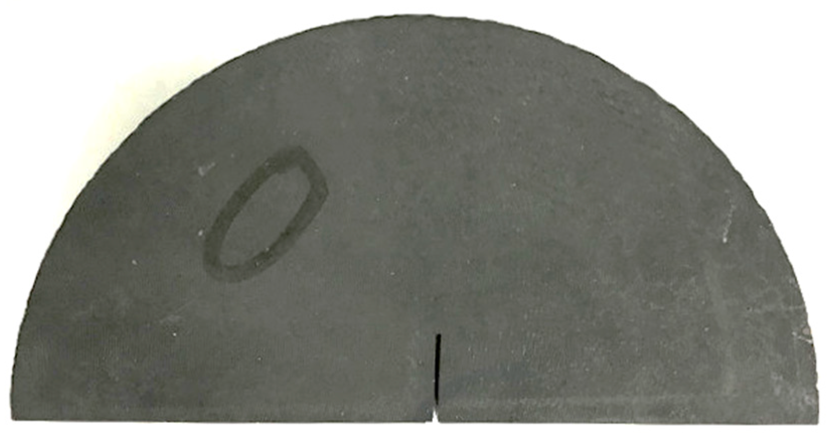
2.1. Sample Preparation

Test samples with an obviously developed bedding plane were drilled from outcropping shale of the Changning in Sichuan, which belongs to the shale gas area in Yibin. To study the bedding effect of dynamic fractures of shale in this area, the collected shale blocks were drilled in parallel and perpendicular to bedding directions. According to the ISRM recommendations for rock materials, the NSCB fracture toughness test standard was employed [16]. The samples were first made into Brazilian discs with a diameter of 100 mm and height of 45 mm, then cut and slit to make NSCB samples, as shown in Figure 1. The specific geometric dimensions are shown in Table 1.

2.2. Test System and Principle
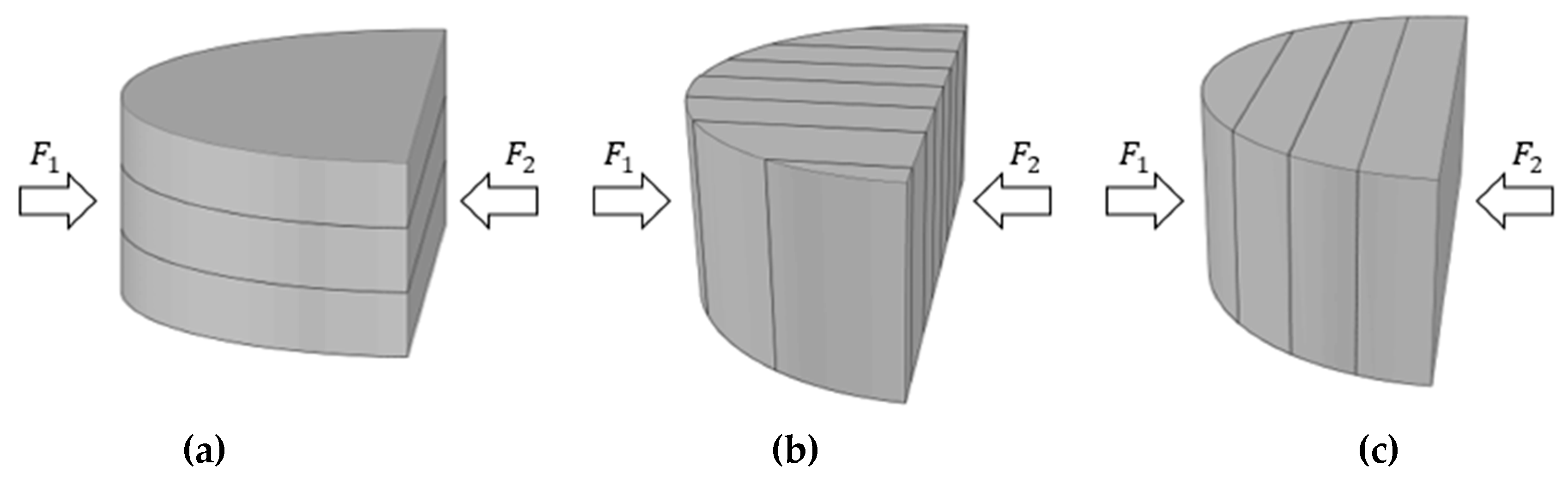
The experiments were carried out at the State Key Laboratory of Geomechanics and Underground Engineering, China University of Mining and Technology (Beijing). Dynamic impact loading tests of the NSCB samples were carried out using a 75 mm diameter SHPB experimental system, the parameters of which are shown in Table 2.
According to the one-dimensional stress wave hypothesis of the SHPB experimental technique, a load F 1 is superimposed on the left end of the sample by an incident wave ε i and reflected wave ε r . The load F 2 on the right end of the sample is calculated by the transmitted wave ε t , as shown in Figure 2. These loads are given by:
F 1 = A E ( ε i + ε r ) ;   F 2 = A E ε t
where A is the cross-sectional area of the bar, E is the elastic modulus of the bar. In the impact loading process, the force balance between the ends of the test sample is the premise for calculating the dynamic crack initiation toughness [13,14,16], i.e., F 1 = F 2 . The SHPB uses a conical striker to strike the incident bar, which produces ramped (half sine) incident wave, allowing the material to establish a stress balance before it breaks. The entire process of shale fracture was simultaneously recorded during the test by high-speed camera to analyze the anisotropy of the fracture mode.
According to the International Society for Rock Mechanics (ISRM) test standard [16], the distance between the two supports of the transmitted bar end was set to S = 55 mm, as shown in Figure 2. The pre-crack dimensionless length was defined as α a = a/R = 0.2 and the dimensionless support spacing was α s = S/D = 0.55. By applying a balancing force to the test sample, the pre-crack in the center of the test sample was subjected to mode I fracture. The stress intensity factor of the crack tip in the test sample is given by:
K I ( t ) = F ( t ) S B R 3 / 2 Y ( α a )
where F ( t ) is the dynamic load at both ends of the test sample; Y ( α a ) is a dimensionless function that depends on the geometric parameters of the prefabricated crack. When 0.15 < α a < 0.5, α s = 0.55 and the Y ( α a ) function can be expressed as:
Y ( α a ) = 0.4670 + 3.9094 α a 8.7634 α a 2 + 16.845 α a 3   ( α s = 0.55 )
According to the basic principles of fracture mechanics [17,18], the instability point of dynamic crack initiation toughness is considered to occur at the maximum load ( F m a x ). The engineering significance of the stress intensity factor is used to determine whether brittle fracturing will occur. According to its definition, the critical value of the stress intensity factor is the fracture toughness of the material. Therefore, the dynamic crack initiation toughness of the test sample is obtained by bringing the maximum load on the end face of the test sample into the mode I crack tip stress intensity factor formula recommended by ISRM:
K I d = F m a x S B R 3 / 2 Y ( α a )

2.3. Loading Method

Figure 3 provides a schematic diagram of the three loading modes of the NSCB test sample. According to the relative orientations of the loading direction and the bedding structural plane, three loading modes were tested: (a) Crack-divider (b) Crack-splitter and (c) Crack-arrester. Among them, the (a) and (b) loading direction is parallel to the bedding, and the (c) loading direction is perpendicular to the bedding. Each of the loading modes was tested at four different impact pressures to evaluate the dynamic crack initiation toughness and regular rupture of shale under different pressure gradients. Three effective samples which a achieved dynamic force balance were tested for each pressure gradient, as shown in Figure 4.

3. Results and Analysis

3.1. Effect of Bedding on Shale Crack Initiation Toughness

Once the ends of the sample reached a balance of force, the dynamic crack initiation toughness was obtained according to the calculation formula. The loading rate depends on the impact velocity of the SHPB bullet. The calculation results are shown in Table 3, Table 4 and Table 5 for the three loading configurations.
Figure 5 shows the relationship between dynamic crack initiation toughness and loading rate of shale for the three loading modes.
Under the same loading conditions, the average dynamic crack initiation toughness values of the three sets of shale NSCB specimens increased in the order Crack-splitter < Crack-divider < Crack-arrester. When the loading direction was perpendicular to the bedding plane, the shale cracking mainly depended on the strength of the rock mass and the influence of the bedding plane was almost negligible, so the dynamic crack initiation toughness was at a maximum. When the loading direction was parallel to the bedding plane, the strength of the weak bedding planes had a significant effect on the dynamic crack initiation toughness. Comparing the two parallel loading modes, under Crack-divider loading, the bedding plane had a partial decrease strength effect, the comprehensive strength of the shale in this direction was reduced, and cracking was easier than for the perpendicular bedding plane loading; for Crack-splitter loading conditions, the sample was completely cracked along the bedding plane direction and its strength mainly depended on the strength of the weak bedding planes. Therefore, its dynamic crack initiation toughness was at a minimum. The test results demonstrated that, after clearing the regular bedding plane distribution of shale, the Crack-splitter loading method achieved better cracking with less energy.
Comparing the three fitting curves in Figure 4 showed that the Crack-splitter had the lowest slope, the slope of the Crack-divider was intermediate, and the Crack-arrester had the maximum slope. The different slopes reflect the loading rate correlation of the samples under different loading conditions. Under Crack-splitter conditions, the strength of the test sample mainly depended on the consolidation between bedding planes. There was no obvious correlation of the loading rate for the consolidation between bedding planes. Under Crack-arrester conditions, the dynamic crack initiation toughness increased significantly with the increase of the loading rate, which indicated that the strength of the shale material played a decisive role. Its regular fracture was consistent with correlations for the loading rates of ordinary rock materials.

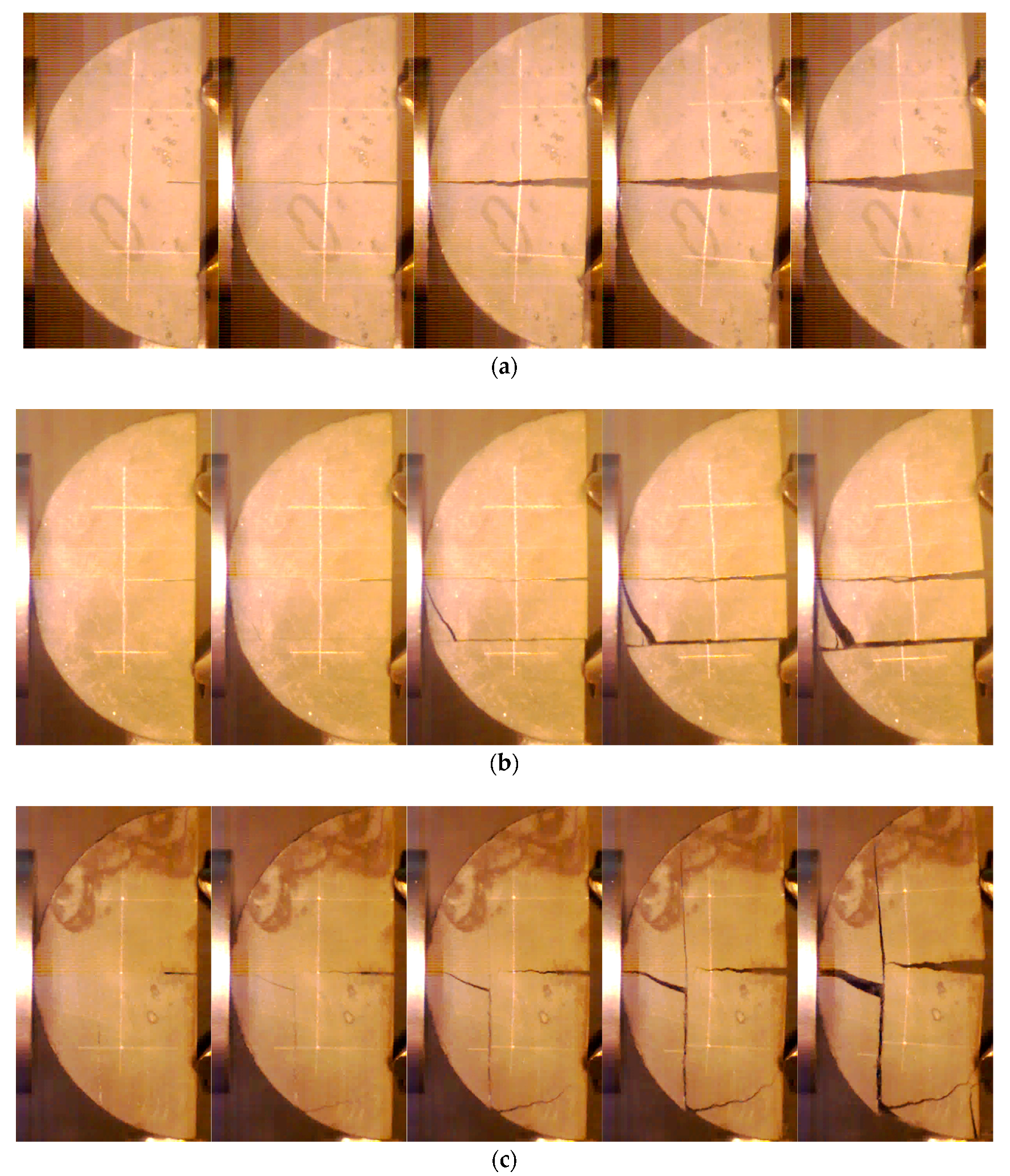
3.2. Shale Fracture Mode

The NSCB samples showed different fracture modes in the three sets of experiments due to the shale bedding plane. Figure 6 displays three typical fracture modes of the specimens, as recorded by a high-speed camera.
In the Crack-divider loading mode, the bedding planes had little influence on the crack initiation and the crack expansion path extended along the pre-crack. The crack was straight and no secondary crack appeared. In the Crack-splitter loading mode, in addition to the pre-crack initiation, a new crack appeared along the weak bedding surface. The two crack expansion paths were essentially parallel. In the Crack-arrester mode, the bedding plane was perpendicular to the loading direction: the pre-crack first cracked in the loading direction, followed by cracking of the bedding plane in the vertical loading direction with a faster expansion, and a branching crack formed at the loading point.
By analyzing the above shale fracture results, it was found that Crack-divider loading has smaller dynamic crack initiation toughness than Crack-arrester loading; cracking was easier, but only a single crack formed and no effective crack network, which made the shale gas spread more easily, was generated. This is not conducive to the formation of shale gas diffusion channels. An effective crack network was formed by Crack-splitter and Crack-arrester loading methods. The dynamic crack initiation toughness of the Crack-splitter loaded shale was the minimum of the three configurations and was the easiest configuration to crack.
Shale is a transverse homogenous material. The difficulty of fracture, that is, the size of dynamic crack initiation toughness and fracture modes are key to the success of shale gas development. These research results provide theoretical support for shale gas development.

4. Discussion

The granite used in Dai et al., exhibited strong anisotropy due to its pre-existing micro-cracks induced by long-term tectonic loading. The index of the mode-I dynamic crack initiation toughness anisotropy of the granite is the ratio of the maximum toughness to the minimum toughness of different specimens under the same loading condition, the smaller this ratio, the smaller the anisotropy. We think the bedding structure of the shale used in this experiment is different from the micro-cracks of granite. The two kinds of rocks are different materials with different structural features. Due to the large distribution of graptolite in bedding plane of shale, the consolidation between bedding planes is weaker, and the strength of the rock mass is larger, so it exhibits different anisotropy from the granite.

5. Conclusions

  • We studied the influence of bedding plane on dynamic crack initiation toughness of shale. Under the condition of parallel bedding plane loading, the bedding plane had a significant influence on the shale cracking. The shale had the lowest crack initiation toughness under Crack-splitter loading. Compared with the bedding plane and perpendicular loading directions, the shale cracking mainly depended on the strength of the rock mass, so the dynamic crack initiation toughness had a high value.
  • We analyzed the effect of the loading rate on shale dynamic crack initiation toughness under three loading modes. The Crack-arrester loading mode had the strongest loading rate correlation and Crack-splitter had the weakest.
  • We analyzed the fracture modes of shale under different loading conditions. When loading was carried out using Crack-arrester, the bedding planes can change the crack expansion direction and consume the most energy. The Crack-splitter loading only required a small amount of energy to achieve effective crack expansion.

Author Contributions

G.Y. and X.L. conceived and designed the experiments; S.C. performed the experiments; X.L. and J.B. analyzed the data; X.L. wrote the paper.

Funding

This paper was supported by the opening project of State Key Laboratory of Explosion Science and Technology (Beijing Institute of Techmology). The opening project number was KFJJ19-10M.

Conflicts of Interest

The authors declare no conflict of interest.

References

  1. Lee, Y.K.; Pietruszczak, S. Application of critical plane approach to the prediction of strength anisotropy in transversely isotropic rock masses. Int. J. Rock Mech. Min. Sci. 2008, 45, 513–523. [Google Scholar] [CrossRef]
  2. Zhao, W.R. Strength properties of anisotropic rock of an argillaceous siltstone. Chin. J. Geotech. Eng. 1984, 1, 32–37. [Google Scholar]
  3. Mao, H.J.; Yang, C.H. Study on influence of discontinuities on mechanical characters of slate. Chin. J. Rock Mech. Eng. 2005, 20, 53–58. [Google Scholar]
  4. Gao, C.Y.; Xu, J.; Li, Z.H.; Deng, J.H. Experimental study of anisotropically mechanical characteristics of sandy slate in Xuefeng Mountain Tunnel. Rock Soil Mech. 2011, 32, 1360–1364. [Google Scholar]
  5. Vernik, L.; Nur, A. Ultrasonic velocity and anisotropy of hydrocarbon source rocks. Geophysics 1992, 57, 727–735. [Google Scholar] [CrossRef]
  6. Kuila, U.; Dewhurst, D.N.; Siggins, A.F.; Raven, M.D. Stress anisotropy and velocity anisotropy in low porosity shale. Tectonophysics 2011, 503, 34–44. [Google Scholar] [CrossRef]
  7. Niandou, H.; Shao, J.F.; Henry, J.P.; Fourmaintraux, D. Laboratory investigation of the mechanical behaviour of Tournemire shale. Int. J. Rock Mech. Min. Sci. 1997, 34, 3–16. [Google Scholar] [CrossRef]
  8. Li, Q.H.; Chen, M.; Jin, Y. Experimental research on failure modes and mechanical behaviors of gas-bearing shale. Chin. J. Rock Mech. Eng. 2012, 31, 3763–3771. [Google Scholar]
  9. Hou, P.; Gao, F.; Yang, Y.G.; Zhang, Z.Z.; Gao, Y.N.; Zhang, X.X.; Zhang, J. Effect of bedding plane direction on acoustic emission characteristics of shale in Brazilian tests. Rock Soil Mech. 2016, 37, 1603–1612. [Google Scholar]
  10. Heng, S.; Yang, C.H.; Guo, Y.T.; Wang, C.Y.; Wang, L. Influence of bedding planes on hydraulic fracture propagation in shale formations. Chin. J. Rock Mech. Eng. 2015, 34, 228–237. [Google Scholar]
  11. Man, K.; Zhou, H.W. Research on dynamic fracture toughness and tensile strength of rock at different depths. Chin. J. Rock Mech. Eng. 2010, 29, 1657–1663. [Google Scholar]
  12. Ni, M.; Gou, X.P.; Wang, Q.Z. Test method for rock dynamic fracture toughness using single cleavage drilled compression specimen impacted by split Hopkinson pressure bar. Eng. Mech. 2013, 30, 365–372. [Google Scholar]
  13. Chen, R.; Xia, K.; Dai, F.; Lu, F.; Luo, S.N. Determination of dynamic fracture parameters using a semi-circular bend technique in split Hopkinson pressure bar testing. Eng. Fract. Mech. 2009, 76, 1268–1276. [Google Scholar] [CrossRef]
  14. Dai, F.; Xia, K. Laboratory measurements of the rate dependence of the fracture toughness anisotropy of Barre granite. Int. J. Rock Mech. Min. Sci. 2013, 60, 57–65. [Google Scholar] [CrossRef]
  15. Goldsmith, W.; Sackman, J.L.; Ewert, C. Static and dynamic fracture strength of Barre granite. Int. J. Rock Mech. Min. Sci. 1976, 13, 303–309. [Google Scholar] [CrossRef]
  16. Zhou, Y.X.; Xia, K.W.; Li, X.B.; Li, H.B.; Ma, G.W.; Zhao, J.; Zhou, Z.L.; Dai, F. Suggested method for determining the dynamic strength parameters and mode-I fracture toughness of rock materials. Int. J. Rock Mech. Min. Sci. 2012, 49, 105–112. [Google Scholar] [CrossRef]
  17. Tang, C.A. Catastrophe in Rock Unstable Failure; China Coal Industry Publishing House: Beijing, China, 1991. [Google Scholar]
  18. Fan, T.Y. Dynamic Fracture Mechanics Principle and Its Application; Beijing Institute of Technology Press: Beijing, China, 2006. [Google Scholar]
Figure 1. Notched semi-circular bend (NSCB) sample.
Energies 12 01636 g001
Figure 2. Loading schematic of split Hopkinson pressure bar (SHPB) setup.
Energies 12 01636 g002
Figure 3. Three loading configurations tested. (a) Crack-divider, (b) Crack-splitter, (c) Crack-arrester.
Energies 12 01636 g003
Figure 4. Dynamic force balance (In: Incident wave, Re: Reflected wave, Tr: Transmitted wave).
Energies 12 01636 g004
Figure 5. Relationships between dynamic crack initiation toughness of shale and loading rate under different loading configurations.
Energies 12 01636 g005
Figure 6. Fracture processes of shale samples for different loading configurations. (a) Crack-divider; (b) Crack-splitter; (c) Crack-arrester.
Energies 12 01636 g006
Table 1. Geometric parameters of notched semi-circular bend (NSCB) samples.
Diameter D/mmThickness B/mmPre-Crack Length a/mmPre-Crack Width /mmPre-Crack Tip Width/mm
10045100.30.1
Table 2. Split Hopkinson pressure bar (SHPB) experimental system parameters.
Bar Diameter/mmIncident Bar Length/mmTransmission Bar Length/mm Density / ( kg / m 3 ) Elastic Modulus/GPaPoisson’s RatioLongitudinal Wave Velocity /(m/s)
753500350078002100.35190
Table 3. Dynamic crack initiation toughness of shale loading with Crack-divider.
Impact   Pressure   ( M P a ) Test Sample Number Loading   Rate   ( 10 4 M P a m / s ) Dynamic   Crack   Initiation   Toughness   K I d   ( M P a m ) Average   Dynamic   Crack   Initiation   Toughness   ( M P a m )
0.54 P 1 -121.6511.5312.17
P 1 -222.3612.38
P 1 -323.7212.61
0.56 P 1 -425.3313.6513.66
P 1 -525.2613.60
P 1 -625.6413.72
0.58 P 1 -728.1514.3814.90
P 1 -828.7214.87
P 1 -929.3915.44
0.60 P 1 -1033.7516.6716.28
P 1 -1132.5116.14
P 1 -1232.4816.03
Table 4. Dynamic crack initiation toughness of shale loading with Crack-splitter.
Impact   Pressure   ( M P a ) Test Sample Number Loading   Rate   ( 10 4 M P a m / s ) Dynamic   Crack   Initiation   Toughness   K I d ( M P a m ) Average   Dynamic   Crack   Initiation   Toughness   ( M P a m )
0.54 P 2 -120.5010.139.87
P 2 -220.119.87
P 2 -319.519.60
0.56 P 2 -423.4111.2311.31
P 2 -523.0611.14
P 2 -624.5611.56
0.58 P 2 -727.2012.0011.99
P 2 -827.4012.08
P 2 -926.7111.89
0.60 P 2 -1030.6012.5712.80
P 2 -1130.1212.24
P 2 -1231.0713.58
Table 5. Dynamic crack initiation toughness of shale loading with Crack-arrester.
Impact   Pressure   ( M P a ) Test Sample Number Loading   Rate     ( 10 4 M P a m / s ) Dynamic   Crack   Initiation   Toughness   K I d ( M P a m ) Average   Dynamic   Crack   Initiation   Toughness     ( M P a m )
0.54 P 3 -121.6412.6713.32
P 3 -222.4113.43
P 3 -323.2413.87
0.56 P 3 -425.8215.6115.75
P 3 -526.6316.40
P 3 -625.5715.24
0.58 P 3 -733.3719.7118.97
P 3 -832.6218.78
P 3 -932.1718.42
0.60 P 3 -1038.0623.7722.51
P 3 -1136.5521.59
P 3 -1237.2322.18

