1. Introduction
With the rapid development of photovoltaic (PV) power-generation technology and the increasing installed capacity of PV power stations, PV power generation has achieved a pivotal position in the global energy system [
1,
2,
3]. Unlike traditional power supply based on synchronous generators, PV power stations have a high degree of controllability. The fault-current characteristics on the PV power station side are affected by the adopted control strategy, control parameters, and fault conditions, among other factors. Additionally, due to the weak infeed characteristic of the PV power station, the fault current in a transmission line will have a lower magnitude than a fault with a conventional power supply [
4,
5,
6]. Therefore, the fault-current characteristics of a PV power station are significantly different from that of a synchronous source. Therefore, the fault analysis and protection schemes used in synchronous source are not suitable for the transmission line connected to a PV power station [
7,
8,
9]. Fault component distance protection offers the advantages of clear directionality, high-speed operation, and is not affected by the pre-fault load current, among others [
8]. The fault component distance protection is widely used in high-voltage transmission lines. Therefore, studying the influence of PV power station on fault component distance protection has a great significance, and corresponding solutions should be proposed to ensure the safe and stable operation of the power systems.
Several researches have addressed control strategies for photovoltaic systems but relatively few papers investigated the effects of PV power stations on fault component distance protection. Based on the fault characteristics of traditional power supply, a fault component distance protection is introduced in [
10]. Using the current characteristics of a thyristor-controlled series compensator (TCSC), the impact of TCSC on fault component distance protection was analyzed, and it was shown that the fault component distance protection may perform an incorrect operation [
11]. A novel weak fault component distance protection was proposed previously, which integrates the performance of a fault component reactance relay and a fault component impedance relay by adjusting the compensated voltage [
12]. Simulations showed that this protection scheme offers an improved sensitivity and selectivity while responding to unbalanced faults. Fault component distance protection based on voltage amplitude comparison was introduced and its merit in covering larger fault resistances was analyzed for unified power flow controller (UPFC) [
13]. References [
10,
11,
12,
13] analyzed fault component distance protection but PV power stations differ from other power systems from the perspective of operating principles and control strategies. Since PV power stations will be interconnected with the existing power networks, the adaptability of the currently protection methods need to be further investigated.
Currently, distance protection is widely utilized in high-voltage transmission networks and several studies have been conducted from the viewpoint of the impact of renewable energy power stations on distance protection. The adaptability problem of typical relay protection schemes to transmission lines emanating from PV power stations was briefly studied in [
14]. The fault-current characteristics within a large PV power station were analyzed in [
15], and a distance protection scheme was proposed to effectively isolate PV power station from faults in overhead transmission lines. In particular, PV power stations have some impact on traditional current protection and may lead to protection maloperation [
16]. The effect of voltage source converter based high voltage direct current (VSC-HVDC) interconnectors on distance protection of transmission lines has also been analyzed in [
17,
18]. Additionally, a novel pilot protection principle was proposed in [
17]. Furthermore, the changes of modular multilevel converter based HVDC (MMC-HVDC) operation mode cause the scope of higher line distance relay Zone 2 to be narrowed, considerably increasing the probability of incorrect operation of distance protection [
19]. The influence of full-scale converter-interfaced renewable energy power plants (CIREPPs) on distance relays installed on transmission lines connected to CIREPPs has been investigated in [
20], and another novel protection scheme was proposed in [
21]. The impact of the several control strategies and the combined impact of a voltage source converter (VSC) with a synchronous condenser on distance protection has been evaluated in [
22]. Results showed that the control strategies should avoid the use of constant reactive power to enhance the reliability of distance protection. In addition, wind farms based on doubly fed induction generators (DFIGs) are widely employed in existing power networks, and numerous studies have been performed on distance protection performance in wind farms [
23,
24,
25,
26]. Considering the specific fault characteristics and complex control strategies of DFIGs in wind farms, a new adaptive distance protection scheme was proposed in [
23] and a distance relay in the time domain based on the resistance- inductance (R-L) differential-equation algorithm was proposed in [
26]. However, none of these studies discussed fault component distance protection or considered specific PV power station characteristics. In particular, unlike conventional distance protection, fault component distance protection is based on a voltage and current fault component, which significantly differs in terms of operating principles and advantages. Furthermore, PV power stations differ from DFIG-based wind power integration systems from the perspective of operation mode and fault-current characteristics. Therefore, it is highly necessary to investigate the adaptability problem of the fault component distance protection on the transmission lines connected to PV power stations.
The rest of this paper is organized as follows.
Section 2 formulates a phasor expression for the fault current on the PV power station side and discusses the fault-current characteristics.
Section 3 describes the general principles for fault component distance protection and uses the phasor expression of fault current to derive the equivalent impedance of the PV power station side and the additional impedance. Furthermore, this section analyzes the influence of equivalent impedance of the PV power station side and the additional impedance on fault component distance protection. The simulation results presented in
Section 4 verify the theoretical analysis of the adaptability of fault component distance protection. Discussion and conclusions are drawn in
Section 5 and
Section 6, respectively.
2. Fault-Current Characteristics at a PV Power Station
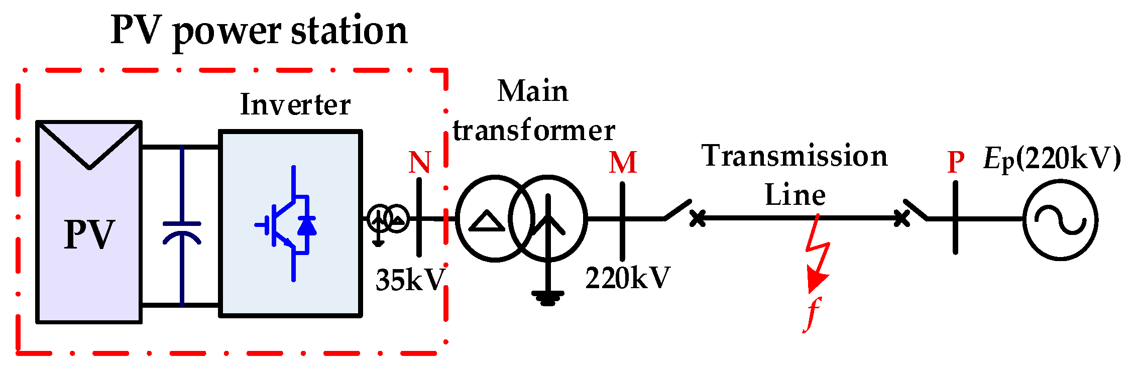
A practical 150-MW PV power station connected to a power grid is used as the model for analysis, as shown in
Figure 1. The M side is the PV power station side and the P side is the system side. The PV power station is connected to a grid with a two-stage boosting structure. First, the direct current (DC) output of the PV power generation unit is inverted into a power frequency alternating current (AC) through the grid-connected inverter, and is then integrated in a 35 kV switch cabinet. Finally, after 35 kV busbar convergence, the power output is boosted and sent to the local power grid through a 220 kV double-winding transformer.
When asymmetric faults occur in the AC transmission line, MP, the three-phase voltage phasor of the PV power station (M side) can be expressed as:
where
U is the voltage magnitude and δ is the initial phase angle of the voltage. The superscripts “+,” “−,” and “0” denote positive, negative, and zero-sequence components, respectively.
η = a, b, and c,
θa = 0°,
θb = −120°, and
θc = 120°; and
k0 is the grounding coefficient. If the fault is a ground fault,
k0 is equal to 1; otherwise,
k0 is equal to 0.
The fault-current characteristics on the M side depend on the control system of a PV grid-connected inverter. Considering unbalanced grid voltage, a current controller under a double synchronous rotating frame is widely used in PV grid-connected inverters [
27,
28]. Therefore, various control targets are set in PV grid-connected inverter control systems, and a unified expression for the reference current under various control targets can be expressed:
where
kχ is a real number that defines the control targets during the fault-ride-through period. The subscripts “ref” denotes the reference value. When
kχ = −1, 0, and 1, the control targets of the PV grid-connected inverter are to eliminate reactive power oscillation, to eliminate negative-sequence current, and to eliminate active power oscillation, respectively.
Pref and
Qref are the reference values of active and reactive power commands, respectively, and
kρ is the grid voltage unbalance coefficient (
kρ =
U−/
U+).
When asymmetrical faults occur in the transmission line, since the step-up transformer (high-voltage side) is connected in star, the fault current in the transmission line comprises positive-, negative-, and zero-sequence components. After the reference currents from the control strategy in (2) have been applied, the phasor expression for steady-state fault current on the M side is as follows:
where
where
Ivm is the magnitude of the positive-sequence current component.
I0 and
θ0 represent the magnitude and initial phase angle of the zero-sequence current, respectively. The magnitude and initial phase angle are determined by the zero-sequence voltage and the impedance of the zero-sequence network, respectively.
For synchronous sources, the fault current of traditional synchronous sources has been well studied, and its expression can be expressed as [
29,
30]:
where
η is phase A, B, or C, and SG denotes the synchronous generator.
and
are the inner potential and reactance of the generator, respectively.
and
are the transient reactance and sub-transient reactance, respectively.
and
are the transient time constant and sub-transient time constant, respectively. ω is the power frequency electrical angular velocity,
φη is the fault inception angle,
Ta is the time constant of the stator windings, and
t0 is the fault inception time.
As seen in Equation (5), the fault current comprises an exponentially decaying cosine wave, a steady cosine wave, and an exponentially decaying DC component. The fault-current characteristics of a synchronous source are primarily determined by the synchronous source’s characteristics and fault conditions. Generally, the fault-current magnitude is much larger than the rated value.
According to Equations (3)–(5) and the vulnerability of power electronic devices, the observed characteristics are summarized as follows:
The fault-current characteristics on the M side differ significantly from those of a synchronous source and are affected by a wide range of factors, such as the control targets, active and reactive power commands, and the voltage unbalance on the grid. The positive-sequence and negative-sequence currents of M side are completely controllable, whereas fault currents of the synchronous source are uncontrollable, which is depended on synchronous source characteristics and fault conditions.
Because of the overcurrent limits of power electronic devices and the controllability of grid-facing inverters, the maximum magnitude of positive and negative-sequence currents in a fault current generally do not exceed 1.2 times the rated value. However, the magnitude of the fault current of the synchronous source is much larger than the rated value of the normal current.
The main transformers usually adopt YNd11 wiring and PV power stations tend to have a weak infeed for the positive- and negative-sequence components. When a ground fault occurs in the transmission line, the fault current consists of positive, negative, and zero-sequence components, and the zero-sequence current dominates. When an ungrounded fault occurs, the fault current does not include a zero-sequence component.
3. Adaptability Analysis of Fault Component Distance Protection
Based on the analysis of fault current of transmission lines in
Section 2, the adaptability of typical fault component distance protection on the M side are analyzed in detail below.
3.1. Principle of Fault Component Distance Protection
The usual operation criteria for fault component distance protection is
where
is the fault component of a compensated voltage and
is the pre-fault voltage at fault point.
and
are the fault components of the voltage and current at relay point M, respectively.
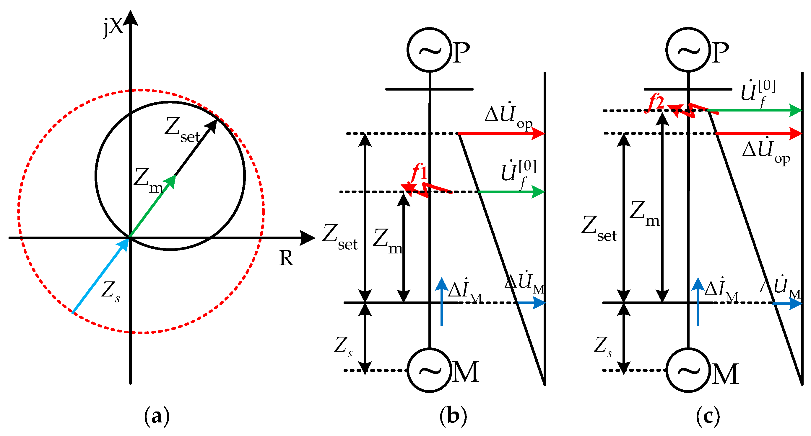
Zone 1 is taken as an example to study the effect of PV power station on fault component distance protection in transmission lines. The analysis method for Zone 1 and the conclusion obtained from Zone 1 are applicable to Zone 2. Zset is the setting impedance of Zone 1 (i.e., 80% of the line impedance).
The operating principle for traditional fault component distance protection is shown in
Figure 2. Since the impedance angles of various elements in fault-additional network for traditional power grid are nearly equal, the phases of
,
, and
are almost the same. In normal conditions,
; therefore, the fault component distance protection will not engage. During an external metallic fault,
and
have the same phase, and as
, the fault component distance protection will still not operate reliably. For the internal metallic fault,
; hence, the fault component distance protection can operate successfully. For a fault at the end of the protection zone, the fault component distance protection is on the edge of operation.
According to (6) and
Figure 2, when a fault occurs in the transmission line, the impedance phase angles of Z
s, Z
m, and Z
set are equal, which is the ideal condition for correct operation of fault component distance protection. Therefore, the operation criterion of (6) can be transformed into impedance form as follows:
In phase-to-phase faults, Z
s and Z
m are obtained as:
In a single-phase-to-ground fault, Z
s and Z
m are obtained as
where Z
s is the equivalent impedance on the M side and Z
m is the measured impedance.
η = a, b, and c,
φφ = ab, bc, and ca.
kl is the zero-sequence compensation coefficient,
kl = (z
0 − z
1)/(z
1), and z
1 and z
0 are the positive sequence and zero-sequence impedance of unit length, respectively.
Generally, the setting impedance is not affected by PV power station connected to the power grid, and the value of Zs is basically unchanged in traditional power grid. However, according to the phasor expression in (3) and (4), the fault-current characteristics on the M side differ significantly from those of conventional power grid. Therefore, Zs and Zm are affected greatly by the interconnection of PV power station, which lead Zs and Zm to differ significantly from their values in traditional power grid in terms of magnitude and phase angle, and may further lead fault component distance protection to operate incorrectly.
3.2. Characteristics of Equivalent Impedance on the PV Power Station Side
According to previous discussion, if the measured impedance is equal to the actual fault impedance, the operating performance of fault component distance protection is determined by the equivalent impedance characteristics of M side. Therefore, this section considers an internal metallic fault as an example to study the equivalent impedance characteristics of the M side, and then analyzes the adaptability of fault component distance protection. The influence of the phase angle change of Z
s on the operating performance of fault component distance protection is shown in
Figure 3. The dotted and solid lines illustrate the cases in which the magnitude of Z
s is small and the magnitude of Z
s is large, respectively.
Figure 3 shows that the phase angle change of Z
s affects the operating performance of fault component distance protection. The following preliminary conclusions can be drawn concerning the operating performance of fault component distance protection:
When 0° < arg(Zs) < 180°, the impedance relationship still meets the operation criterion of impedance form in Equation (7). The fault component distance protection will operate correctly; however, the large magnitude of Zs decreases the sensitivity of the fault component distance protection.
When −90° < arg(Zs) < 0° and the magnitude of Zs is small, the impedance relationship still meets the operation criterion of the impedance form. When the magnitude of Zs is large, the impedance relationship does not satisfy the operation criterion of impedance form. Due to the weak infeed characteristic of the PV power station, the magnitude of Zs is much larger than that in traditional power grid. Therefore, the fault component distance protection will operate incorrectly.
When −180° < arg(Zs) < −90°, the impedance relationship does not satisfy the operation criterion of impedance form, and the fault component distance protection will be more sensitive to changes of Zs. Therefore, the fault component distance protection will operate incorrectly.
3.2.1. Characteristic Analysis of Zs under Phase-to-Phase Fault
When an internal fault occurs at the transmission line MP (
f), the phasor expressions for the three-phase voltage and three-phase current of M side before the fault can be expressed as follows:
where ∆
δ is the jump angle of the positive-sequence voltage,
kλ is the coefficient of the positive-sequence voltage sag, and
P0 is the power output of the PV power station during normal operation.
PV power station usually adopts the control target of eliminating a negative-sequence current, so
kχ = 0. Assuming that an internal phase-to-phase fault occurs at
f, if (3), (4), and (10) are substituted into (8), the magnitude and phase angle of Z
s can be calculated as
where
is the magnitude of the difference between the two phases of the voltage when a phase-to-phase fault occurs (refer to
Appendix A Equation (A1)), and C
+ and C
− are coefficients describing the distribution of the positive- and negative-sequence current. When the PV power station adopts the control target of eliminating the negative-sequence current, then C
− = 0.
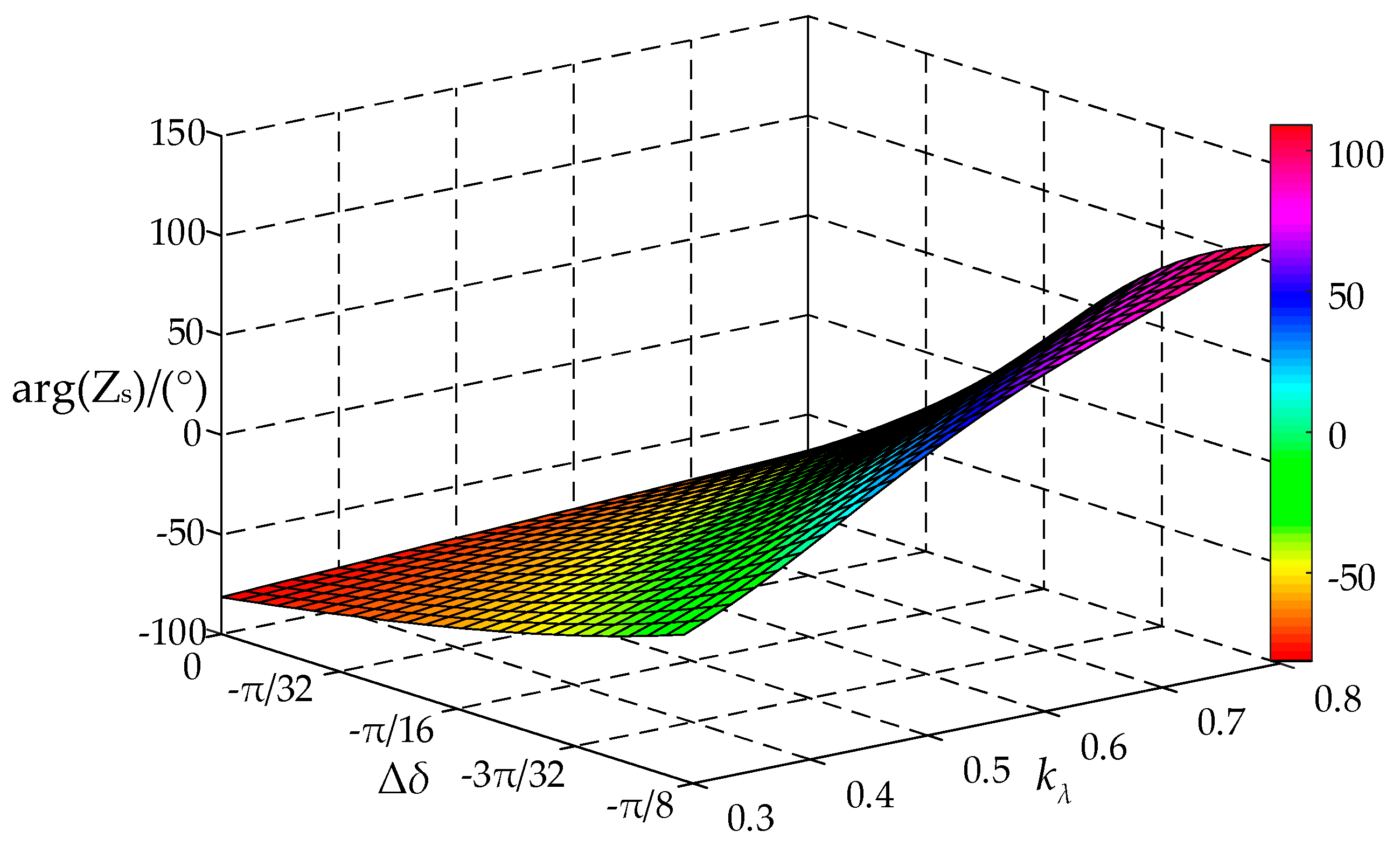
Due to the weak infeed characteristic of PV power station, the magnitude of Zs is much larger than that in a traditional power grid. According to (4) and (12), arg(Zs) is related to the variables of ∆δ, P*, Q*, and kλ. The difficulty of theoretical analysis increases significantly owing to the presence of several variable factors. When the three-phase fault with 0 Ω fault resistance occurs, kλ = 0 (minimum value). kλ increases as the fault resistance increases. When the value of fault resistance is infinite, kλ = 1 (maximum value). However, it is impossible that the value of fault resistance is infinite when a fault occurs. Three-phase metallic fault rarely occurs. According to simulation data, the range of ∆δ is generally between −25° and 5°. In view of most possible conditions, the following assumptions are applied: (1) the coefficient of the positive-sequence voltage sag: 0.3 ≤ kλ ≤ 0.8 and (2) the positive-sequence voltage jump angle: −π/8 < ∆δ < 0.
The arg(Z
s) with different
kλ and ∆
δ under the control target of eliminating negative-sequence current is shown in
Figure 4, drawn using MATLAB/2016B.
Figure 4 shows that the arg(Z
s) lies between −80° and 110° under these conditions. Furthermore, as derived in
Figure 3, when −180° < arg(Z
s) < 0°, the fault component distance protection will fail to operate.
In summary, when an internal phase-to-phase metallic fault occurs at f, the magnitude of Zs will be large, and the phase angle is related to the active and reactive power commands, control targets, and fault conditions. Therefore, when −180° < arg(Zs) < 0°, the fault component distance protection will fail to operate.
3.2.2. Characteristics of Zs under a Single-Phase-to-Ground Fault
When an internal phase-A-to-ground metallic fault occurs at
f, by substituting (3), (4), and (10) into (9), the magnitude and phase angle of Z
s is calculated as
where
and ∆
θua are the magnitude and phase angle of the A-phase voltage fault component during the phase-A-to-ground fault, respectively (refer to
Appendix A (Equations (A2) and (A3)).
As ∆
θua is unaffected by the PV power station, and
Ivm/
INm ≈ 1.2 and
I0/
INm > 3, the fault current is dominated by the zero-sequence current. Therefore, ∆
θia ≈
θ0 and 0° < arg(Z
s) < 180°. Generally, owing to the weak infeed characteristic of PV power station, the magnitude of Z
s in the PV power station side is larger than that in a traditional power grid. As derived in
Figure 3, when an internal phase-A-to-ground metallic fault occurs at
f, the fault component distance protection operates reliably.
3.3. Characteristics of Measured Impedance
Above, the equivalent impedance on the M side was analyzed theoretically, and the influence of Zs on the fault component distance protection was considered under the assumption that Zm is equal to the actual fault impedance (Zk). The PV power station’s effect on Zm is considered below and further analysis of the influence of Zm on fault component distance protection is given.
When a fault with fault resistance R
f occurs at
f, the measured impedance (Z
m) will be:
where
and
are the fault-current components on M and P side, respectively, Z
k is the actual fault impedance (positive-sequence line impedance between the protection location and the fault location
f), and ∆Z is the additional impedance caused by the fault resistance.
For the internal metallic fault, the measured impedance will be equal to the actual fault impedance. If the fault resistance Rf is non-zero, ∆Z will appear in the measured impedance, which means that the distance relay will unable to calculate the actual fault impedance accurately. The characteristic of ∆Z will differ for different faults; the following classification discusses the characteristics of ∆Z.
3.3.1. Characteristic Analysis of ∆Z under a Phase-to-Phase Fault
This section takes an internal phase B-to-phase C (BC) fault as an example to study the characteristics of ∆Z and then analyzes the influence of PV power station on the measured impedance. In this case, ∆Z can be expressed as
where
and
are the magnitudes of the difference between the BC-phase fault-current components on the P side and M side, respectively. And
are the phase angles of the difference between the BC-phase fault-current components on the P and M side, respectively.
Generally,
is determined by the characteristics of traditional power supply, and
is affected by the control parameters and fault conditions. From (3), (4), and (10), the value of
can be calculated as
where
θBC = 3π/2·
is large because of the weak infeed characteristic of PV power station. In addition, the characteristics of ∆Z are mainly determined by
. According to Equations (4) and (18),
values are affected by several factors, such as the control targets, active and reactive power commands, and voltage unbalance on the grid. Consider a phase-to-phase fault as an example. When the value of fault resistance
Rf equals 0,
kρ = 1 (maximum value). When the value of fault resistance
Rf is infinite,
kρ = 0 (minimum value). However, the value of fault resistance is not zero, and it cannot be infinite. Therefore, the range of
kρ is between 0 and 1. Generally, the
Pref value during the fault is less than 1.0 pu and is related to the positive-sequence voltage sag. Therefore, to simplify the analysis, the following assumptions are applied: (1) the active power reference values: 0.2 p.u. ≤
Pref ≤ 0.8 p.u.; and (2) the grid voltage unbalance coefficient: 0.2 p.u. <
kρ < 0.8 p.u. The
Pref and
kρ are within a reasonable range, and the range of
Pref and
kρ can cover most cases.
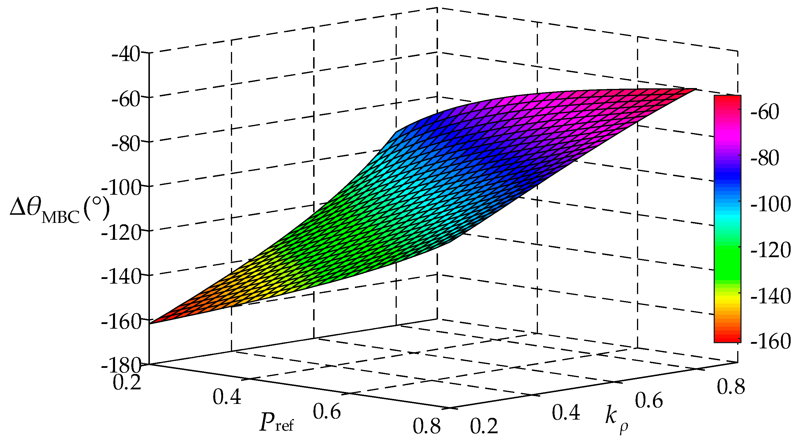
The ∆
θBCM with different
Pref and
kρ under the control target of eliminating active power oscillations is shown in
Figure 5, which was drawn using MATLAB/2016B.
Figure 5 shows that the range of ∆
θBCM is between −160° and −60°. The difference in phase angle between both sides may express ∆Z as a capacitive or inductive impedance, which significantly differs from those of a conventional power grid. Therefore, the controllability of ∆
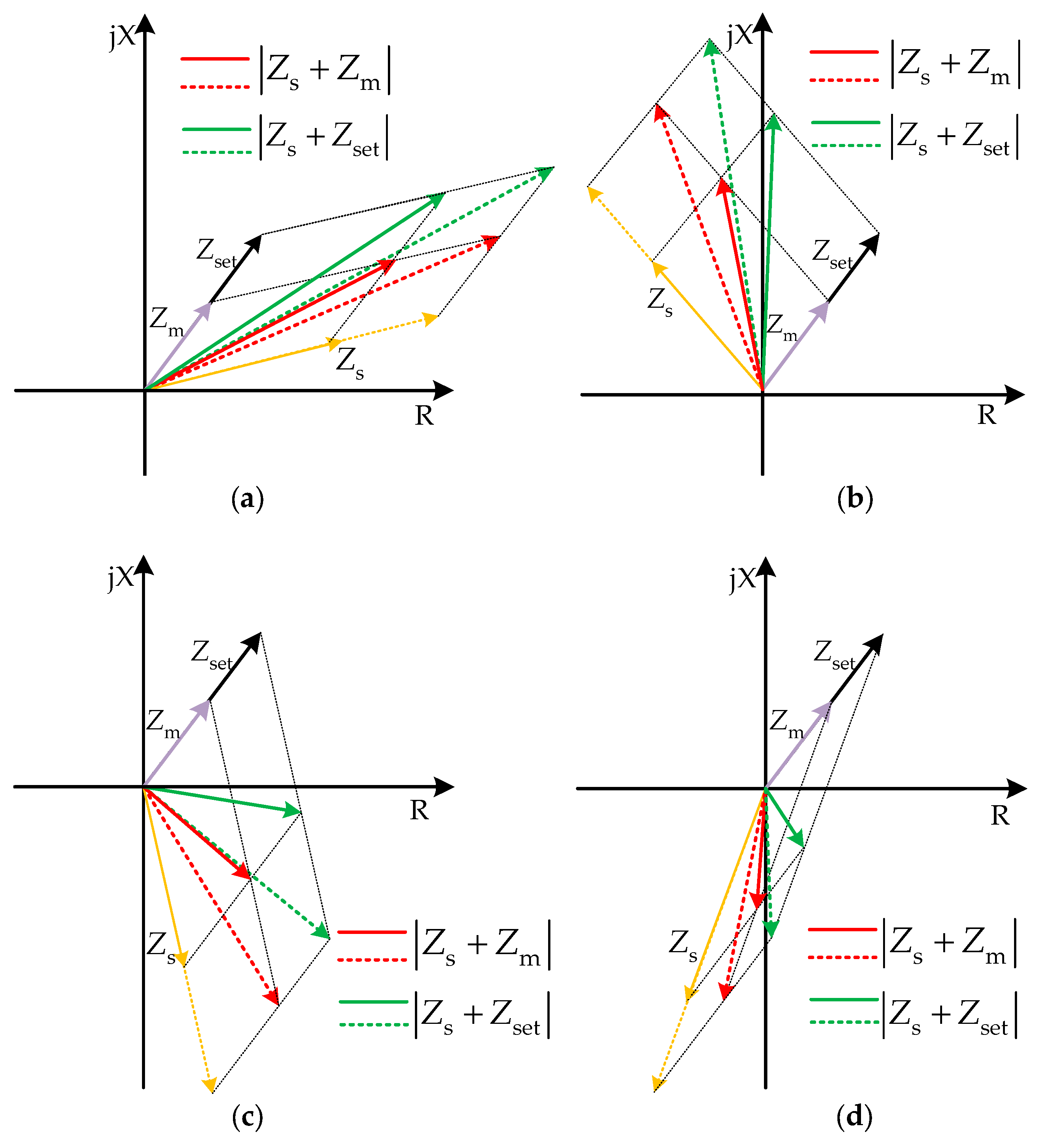
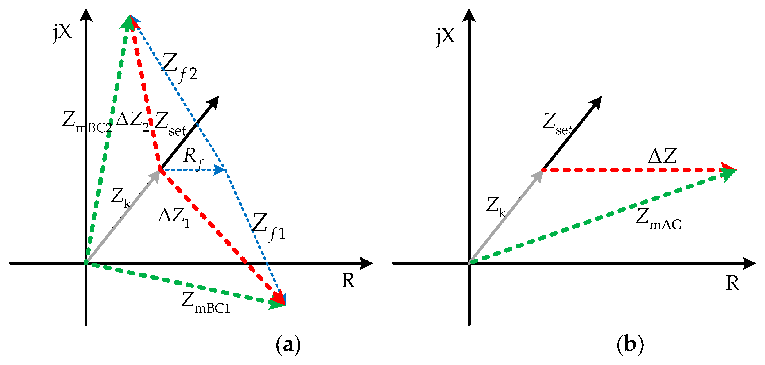
θBCM may causes the distance relay to be unable to accurately calculate the actual fault impedance. The impedance plane of measured impedance for an internal BC fault is shown in
Figure 6a. The characteristics of Z
s with different influence factors.
3.3.2. Characteristic Analysis of ∆Z under a Single-Phase-to-Ground Fault
When
kχ is zero and with the weak infeed characteristic of PV power station, the positive-sequence current is less than the zero-sequence current and can be neglected. In this case, the zero-sequence compensation coefficient
kl can be assumed to be a real number. In this case, ∆Z can be expressed as:
where
and
are the zero-sequence currents measured at the M and the P side. Assuming that the zero-sequence impedance angles on the M and P side are equal,
is in phase with
, and the zero-sequence current magnitude on the M side is smaller than that on the P side. Therefore, the additional impedance yields a large resistance value. The impedance plane of measured impedance for an internal AG fault is shown in
Figure 6b.
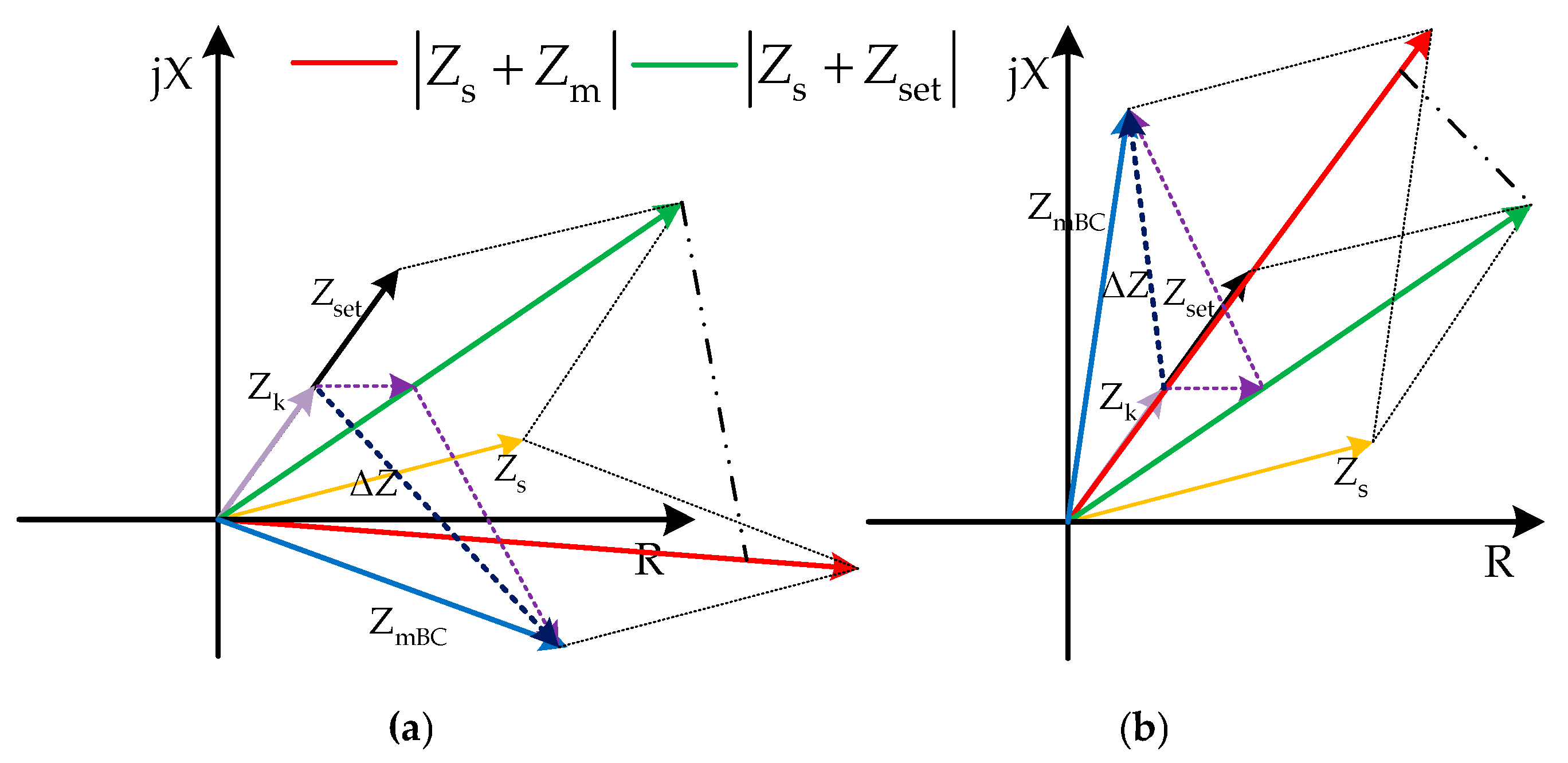
3.3.3. Influence of the Measured Impedance on Fault Component Distance Protection
According to the discussion in the previous section, the measured impedance was affected greatly by the fault resistance and fault current, which make the distance relay unable to calculate the actual fault impedance accurately. To simplify the analysis, this section considers an internal BC fault as an example to study the influence of the measured impedance on the operating performance of fault component distance protection. In this case, the influence of the measured impedance on the operating performance of fault component distance protection is shown in
Figure 7.
As derived in
Figure 3, when an internal metallic fault occurs at
f and the 0° < arg(Zs) < 90°, the fault component distance protection will operate reliably. However, when an internal fault with fault resistance occurs at
f, it can be seen from
Figure 7 that the additional impedance (∆Z) will make the distance relay unable to calculate the actual fault impedance accurately, which may enhance the adverse influence of Z
s on fault component distance protection in case that the PV power station is connected to a power grid; further, it will lead fault component distance protection to operate incorrectly.
4. Simulation Verification and Analysis
To verify the correctness of the theoretical analysis discussed above, a 150-MW PV power station, as shown in
Figure 1, was modeled in PSCAD/EMTDC. The rated power of the PV station is
SPV = 150 MVA, rated capacity of the main transformer is
ST = 200 MVA, the rated change ratio is
kT = 230/37 kV, the connection type of main transformers is YNd11, and the short-circuit impedance is 16%. The rated voltage of the transmission line is 220 kV, the line length is
lMP = 50 km, and the positive-sequence and zero-sequence impedance parameters of the unit length of the line are 0.107 + j0.427 and 0.535 + j1.153 Ω/km, respectively. The equivalent positive-sequence impedance and zero-sequence impedance of the power grid system are 0.6 + j6.972 and 0.8 + j10.95 Ω, respectively.
To prevent overcurrent from damaging power electronic switching devices and improve the safety of inverter operation, the actual PV power station usually adopts the control target of eliminating negative-sequence current. Therefore, the simulations discussed below focus on the theoretical analysis of fault component distance protection based on the control target of eliminating negative-sequence current.
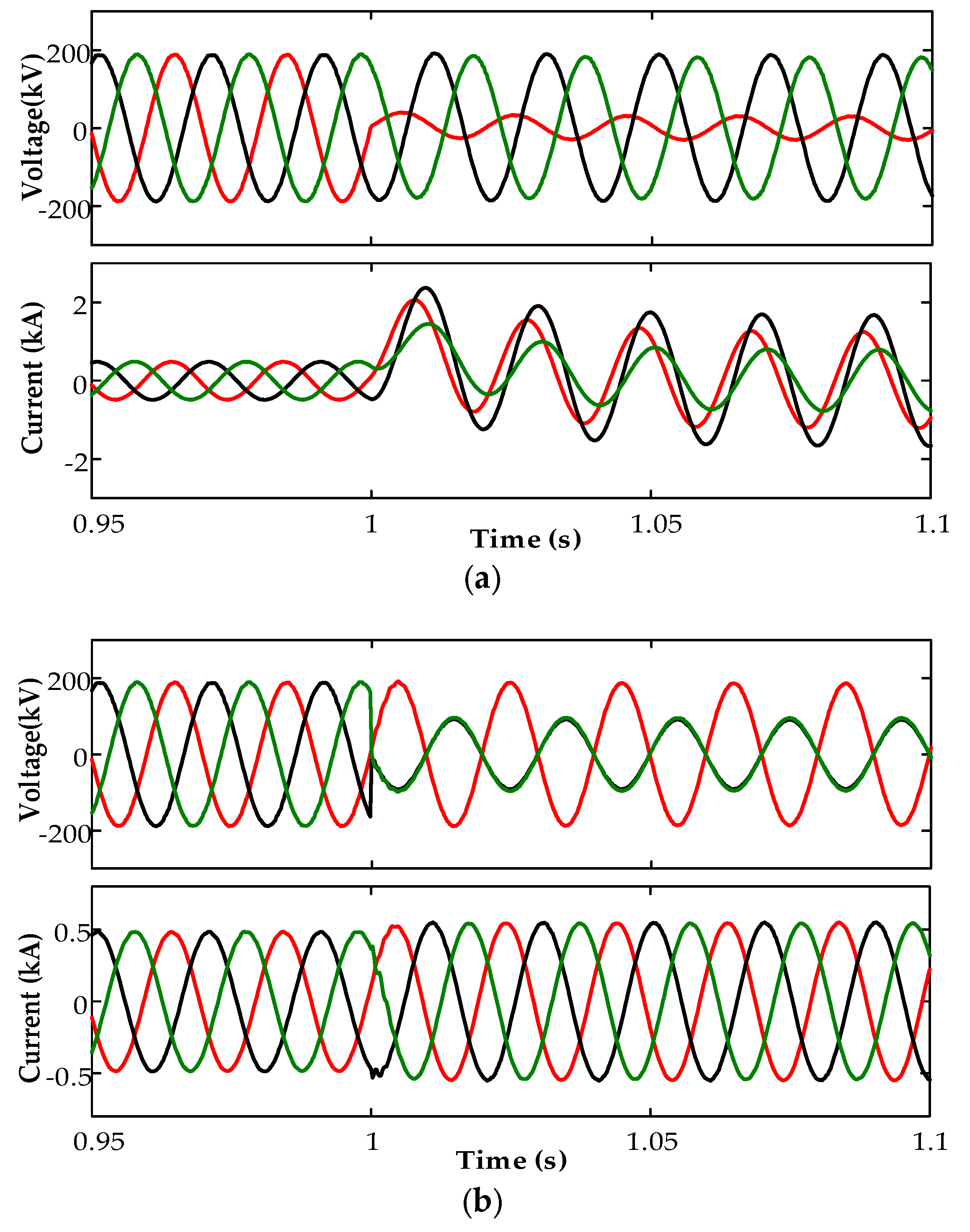
4.1. Simulation Verification of Fault-Current Characteristics on PV Power Station Side
Figure 8 shows the simulation results of various faults occurring at 40% of the length of the transmission line from the relay located on the M side (
f). The red, black, and green curves plot the A, B, and C phases, respectively. For fault-current waveforms of the AG fault in
Figure 8a, the fault current is dominated by the zero-sequence current, and the phase angles of the three-phase currents are nearly equal. However, for the fault current waveforms of the BC fault in
Figure 8b, the fault current is solely positive-sequence current, the three-phase current is symmetrical, and its magnitude does not exceed 1.2 times the rated value. These fault-current characteristics are consistent with the theoretical analysis presented in
Section 2.
4.2. Simulation Verification of Equivalent Impedance Characteristics on PV Power Station Side
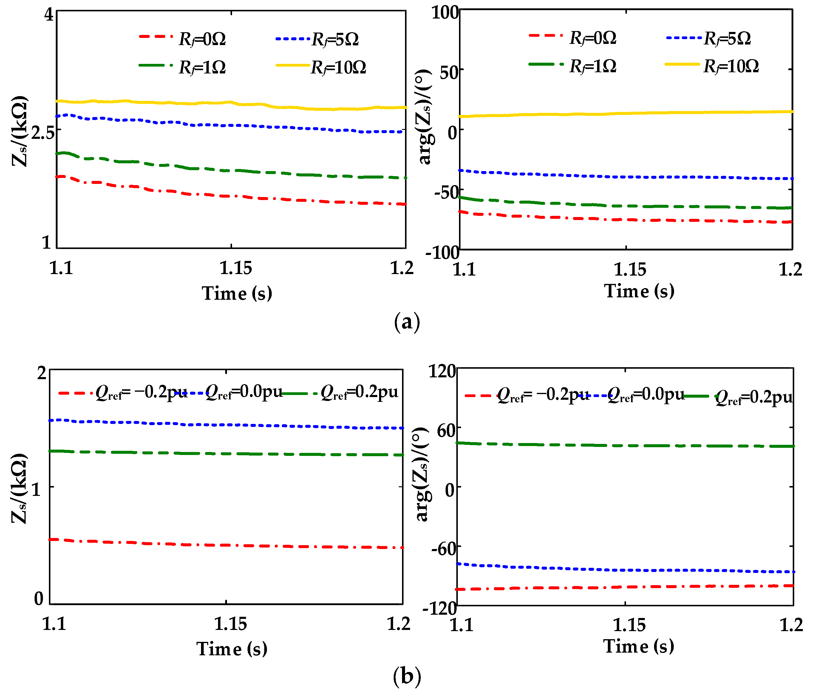
Figure 9 shows the characteristics of Z
s with different influence factors under BC fault at point
f.
The characteristics of Z
s with different fault resistances are shown in
Figure 9a. As shown in
Figure 9a, the magnitude of Z
s is large in all cases, and increases as the fault resistance increases. When R
f = 0, the phase angle of Z
s is −76°. Upon comparing different values of R
f, one can see that arg(Z
s) also increases as the fault resistance increases. Meanwhile, arg(Z
s) is converted from the range of −90° to 0° to 0° to 90°. This conversion means that the fault component distance protection is very likely to malfunction.
The characteristics of Z
s with different reactive power commands (
Qref) are shown in
Figure 9b. If
Qref is small or negative, the −180° < arg(Z
s) < 0°, and then the fault component distance protection will operate incorrectly; if
Qref is positive, the 0° < arg(Z
s) < 180°, and the distance-relay fault protection will operate correctly.
4.3. Simulation Verification of Measured Impedance Characteristics
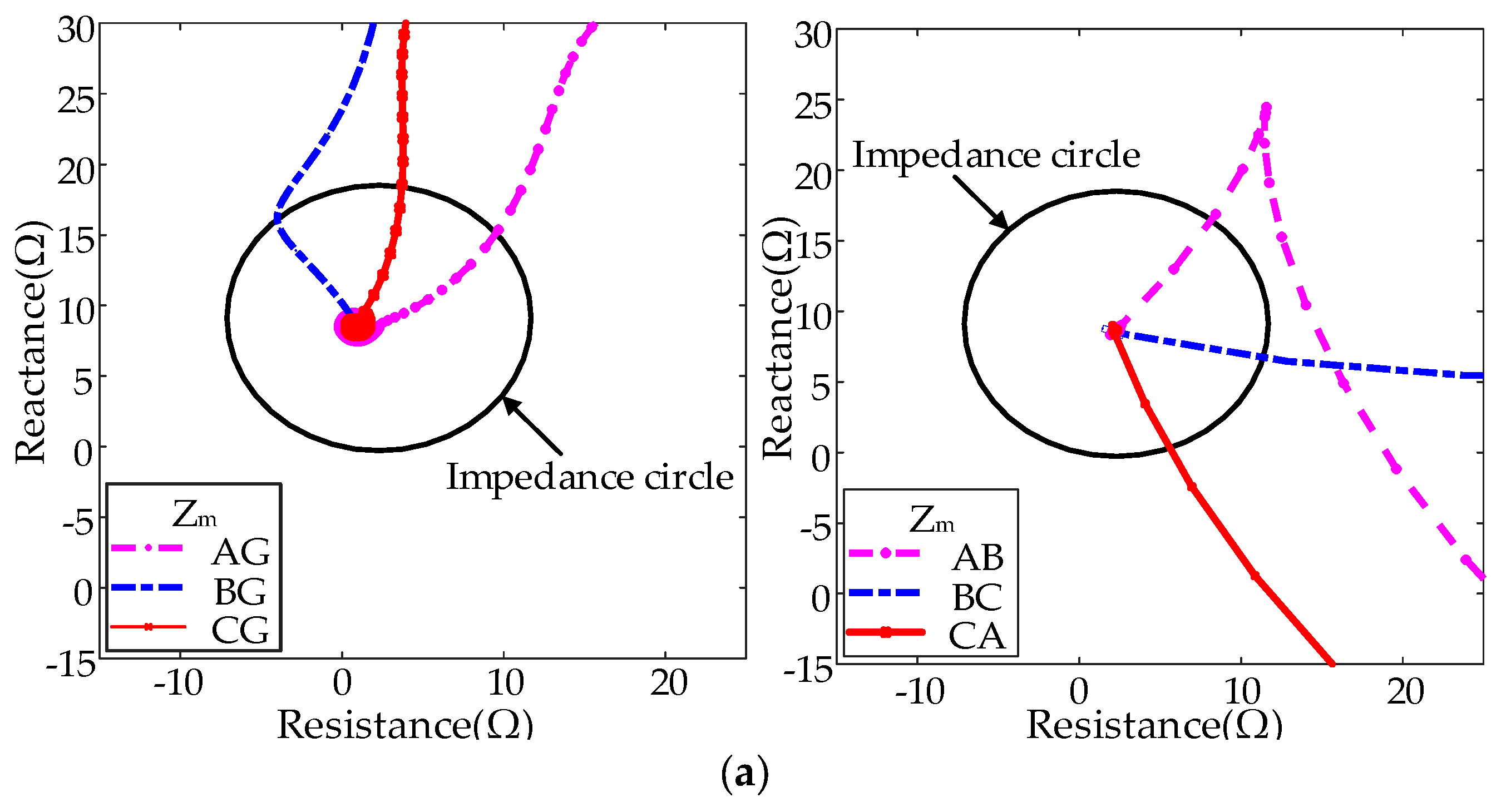
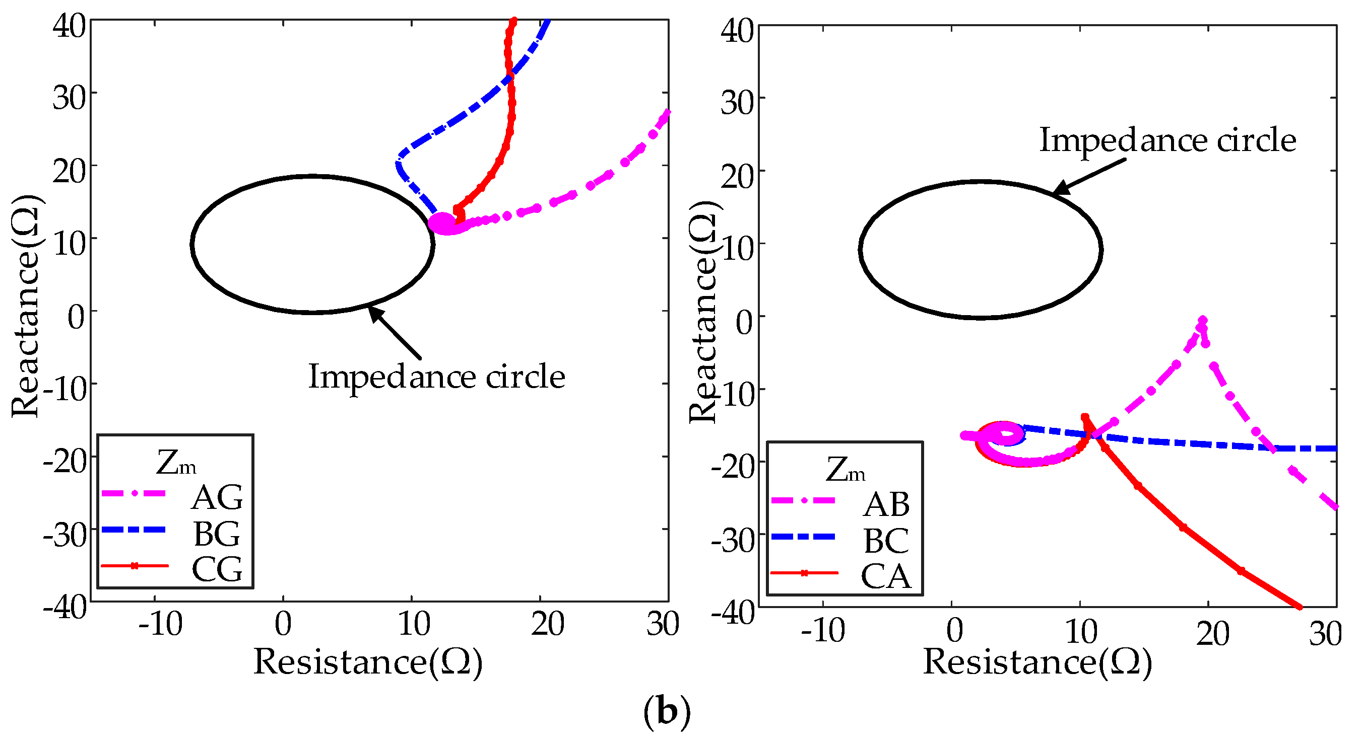
Figure 10 shows the simulation results of the measured impedance (Z
m) under unbalanced faults occurring at
f.
Figure 10a shows the simulation results of Z
m under different metallic faults, and
Figure 10b shows the simulation results of Z
m under unbalanced faults with 5-Ω fault resistance.
As shown in
Figure 10a,b, when a metallic fault occurs, the distance relay can calculate the actual fault impedance accurately. When faults with 5-Ω fault resistance occur, influenced by the fault current of the M side, the measured impedance is much larger than the actual fault impedance, and the distance relay will be unable to calculate actual fault impedance accurately. Therefore, the impedance measured by the distance relay on the transmission line will fall outside the protection zone, as shown in
Figure 10c,d. When a phase-to-phase fault occurs, Z
m will include a large imaginary component, and the measured impedance will differ greatly from the actual fault impedance.
4.4. Simulation Verification of Operating Performance of Fault Component Distance Protection
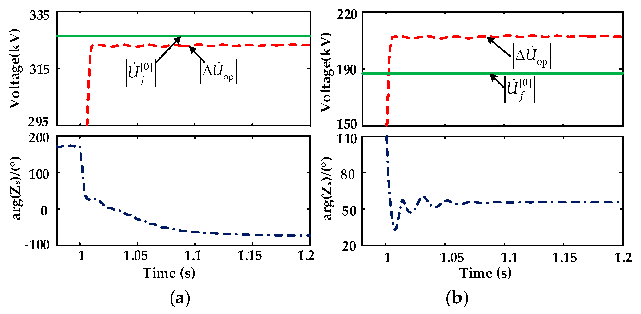
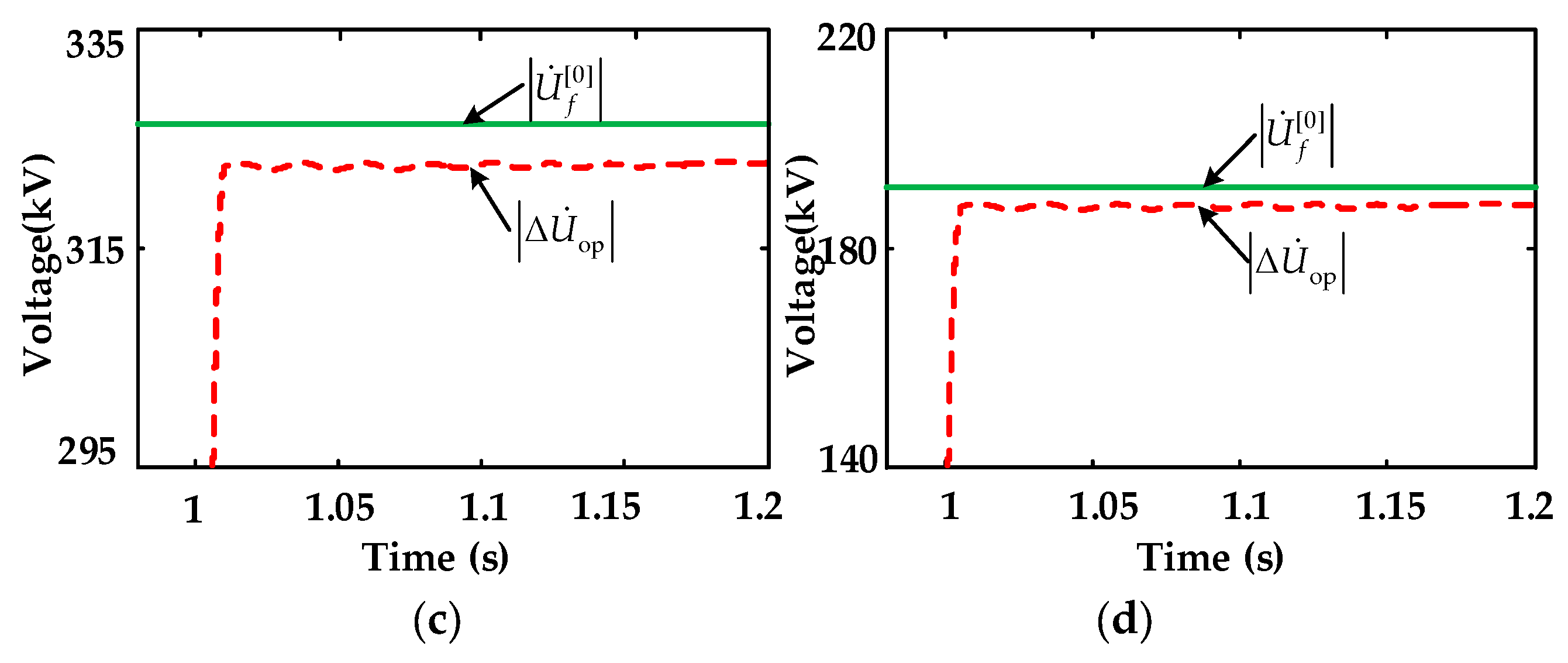
Figure 11 shows the operating performance of fault component distance protection under various fault conditions.
Figure 11a,b presents the operating performance of fault component distance protection under an AG metallic fault and a BC metallic fault, respectively.
Figure 11c,d present the operating performance of fault component distance protection under an AG fault with 5 Ω fault resistance and a BC fault with 5 Ω fault resistance, respectively.
As shown in
Figure 11a, when an AG metallic fault occurs on line MP at location
f, the 0° < arg(Z
s) < 90° and the fault component distance protection can operate successfully. Similarly, as shown in
Figure 11b, when a BC fault occurs on line MP at
f, the −180° < arg(Z
s) < −90°, and the fault component distance protection will fail to operate in this case. These simulations of the fault component distance protection are consistent with the theoretical analysis discussed in
Section 3.
The results shown in
Figure 11c,d imply that the fault component distance protection will fail to operate if a fault with fault resistance occurs in the transmission line. These simulations of fault component distance protection are consistent with the theoretical results discussed in
Section 3.
6. Conclusions
This study derived the analytical expressions of fault currents on M side under different control targets. Based on the fault-current characteristics, the adaptability of fault component distance protection was analyzed. First, the fault-current characteristics on the M side differ significantly from those of a synchronous source and are affected by a wide range of factors, such as the control targets, active and reactive power commands, and voltage unbalance on the power grid. Then, the analysis showed that the equivalent impedance of M side tends to be large, and the phase angle of equivalent impedance is greatly affected by the active and reactive power commands, control targets, and fault conditions. In particular, when −180° < arg(Zs) < 0°, the fault component distance protection will operate incorrectly.
Third, the analysis showed that the measured impedance is affected by the related parameters in the control strategy, fault resistance, fault location, and fault type, among others. Unlike conventional synchronous generators, the measured impedance differs significantly in terms of magnitude and phase angle, which will make the distance relay unable to calculate the actual fault impedance accurately. Therefore, errors in impedance measurements can exacerbate problems with the adaptability of fault component distance protection when PV power stations are interconnected with a power grid.
Finally, theoretical analysis and simulations showed that existing fault component distance protection are not suitable for fault protection in transmission lines connected to PV power stations. If a ground metallic fault occurs in the transmission lines, the fault component distance protection will operate correctly. However, if the fault type is a phase-to-phase metallic fault or the fault with fault resistance, the fault component distance protection may fail to operate.


