Abstract
The inductive reaction sphere (RS) brings the benefit of simple, economical, and miniaturized design, and it is capable of multi-DOF torque generation. Thus, it is a suitable choice for the angular momentum exchange actuator in attitude control of micro-spacecrafts. To synthesize symmetric distribution of eddy currents and improve the speed and stability of rotation, a novel 4-pole winding design is proposed. However, the developed simplified analytical model shows that reduced pole number degrades the torque generation. To enhance the output torque of 4-pole RS, its curved cores and electromagnets are redesigned to enable the side teeth to be functional. As the analytical torque model for the RS with the slotted cores is not available, a constrained optimization problem is formulated, and the optimized parameters are calculated based on the prediction model from supported vector machine and finite element analysis. The lab prototypes are developed to validate the proposed design and test the speed performance. The experimental results show that the 4-pole RS prototype obtains a stable rotation over 700 rpm about X, Y and Z axis respectively with the angular momentum of 0.08 kg·m/s, being superior to the 6-pole counterpart.
1. Introduction
Besides the orbit control, the attitude control is essential to prevent rollover of the spacecraft and to ensure its antennae consistently directs to a fixed point on the Earth surface [1]. Since spacecrafts are free-floating in space, one way to adjust their attitudes is to transfer the momentum from a rotating actuator to the spacecraft body back and forth. When the actuator changes its rotational speed, the spacecraft will counter-rotate to remain the conservation of angular momentum.
The concept of using a spherical rotor as a momentum exchanger for spacecrafts attitude control starts in the 1960s [2,3,4]. This is where the name “reaction sphere (RS)” comes from. Compared with other momentum exchange actuators such as the flywheel [5] and the control moment gyroscope [6], the RS can generate 3-axis output torque within one single actuator, thus giving a compact design. In addition, the torques generated in the RS around different axes are naturally decoupled, which simplify the controller design. However, due to the difficulties in designing a working prototype, the RS had not gained much attention for decades. With the rapid development of micro-spacecrafts from the early of this century, the demand for minimization design of the attitude control system has helped the reaction spheres get noticed again [7,8].
A RS can be driven by several single axis motors or a single spherical motor. The former scheme drives the reaction sphere with multiple wheels rotating at desired directions [9,10,11,12]. These wheels are independently driven by their corresponding single-axis motors. The later scheme considers the reaction sphere as the rotor of a spherical motor, where the stator of the motor is designed in a spherically symmetric way. No mechanical output shaft exists in these spherical motors. The driving principle can be inductive [13,14,15,16,17,18,19], permanent magnet (PM) [7,8,20,21], hysteresis [22,23], variable reluctance [24] and ultrasonic [25,26].
Among all types of reaction spheres, the inductive RSs have the advantages of simple design and high reliability, making them be more competitive in commercial applications. Inductive RSs follow the same driving principle as the traditional single-DOF induction motors. The stator of an induction reaction sphere is excited with alternating currents. Then the generated rotating magnetic fields cut the rotor conductor to produce the induced currents. The interaction between the induced currents on the rotor and the magnetic fields in the air gap produces Lorentz force, which drives the rotor to rotate in the direction of the rotating magnetic fields. Compared with conventional induction motors, inductive RSs feature the capacity of generating multi-DOF rotating magnetic fields.
One class of inductive reaction spheres obtains this capacity via distributed electromagnets [16,17,18]. A 3D reaction sphere design is proposed in [17], where 3 pairs of electromagnets are put orthogonally in space. A one-DOF inductive RS prototype is developed, with 4 electromagnets for rotation and 1 electromagnet for levitation. With the similar design, a well-developed one-DOF inductive RS prototype is presented in [18]. It reaches the maximum speed of 13,500 rpm and the maximum torque of 0.7 Nm in the performance test experiments. However, this prototype has the disadvantage of large stator. The stator occupies much more space than the rotor. An inductive RS design with 20 distributed electromagnets is proposed in [16]. Subsequently, a one-DOF prototype is developed, but no performance data are reported. The control strategy can be very complicated if the suspension and rotation are driven by the same electromagnets.
The other class of inductive RSs gains this capacity via curved inductors. This type of inductive RSs tends to have a more compact design over the ones with distributed electromagnets, for the coils of curved inductors are extended along the rotor surface but coils of electromagnets are extended radially. The curved inductors in inductive RSs can be arranged to be vortex-like [13,19] and orthogonal [13,14,15]. The vortex-like arrangement can get the spherical rotor half exposed. This feature makes it be suitable for applications like mobile platforms and robots and the case with no requirement of full angle rotation. The design and control aspects of a 3D spherical induction motor for mobile robots is presented in [19], featuring the vortex-like arranged four curved inductors and the half exposed spherical rotor. The angular velocity and orientation control studies enable a large prototype to rotate along arbitrary axes under the speed of 300 rpm, which validate the feasibility of the vortex-like arrangement. In orthogonal arrangement, the curved inductors go all around the rotor and form the closed structure. It is well fit for the devices working through momentum exchange. Patent [14] proposes a magnetic bearing inductive RS design with three pairs of curved inductors orthogonally arranged. In this design, the AC windings for rotation and the DC windings for suspension are placed on the same teeth of curved cores. No relevant feasibility research is found of this design.
In this paper, a compact design of inductive RS is proposed, featuring 12 curved inductors in orthogonal arrangement for rotating and 6 electromagnets in pairs for magnetic bearing. The overall design enables the RS to generate three-DOF rotation under magnetic levitation. To synthesize symmetric distribution of eddy currents and improve the stability during high-speed rotation, the 4-pole winding is proposed instead of the intuitive 6-pole design. However, the analytical torque model with simplified slotless assumption indicates that reduced pole number degrades the torque generation. To enhance the capability of the torque synthesis in the 4-pole winding design, the slotted iron-core is imposed in design of curve stators. In addition, the electromagnets in the RS are redesigned to be the cross-shape, so that two more slots near the notches of the iron-core curve stator become functional. Such design improves the uniformity of the eddy current and magnetic field induced along the stator circle. As the analytical torque model for the RS with slotted curve stator is not available, a constrained optimization problem is formulated for torque maximization in the RS. From here, the data-based regression algorithms are applied to find the optimal design parameters. Speed test experiments on the developed prototype are conducted to show the superior performance of the optimized 4-pole inductive RS design over the conventional 6-pole counterpart.
2. Structure Design
2.1. Rotor
The attitude adjustment of the spacecraft is realized through the exchange of angular momentum between the rotating sphere and spacecraft body. The rotor of the spherical motor is the carrier of angular momentum. To store more angular momentum, large moment of inertia (MOI) is preferred with a fixed amount of mass. In rotor structural design, MOI of a hollow and uniform sphere is calculated by
where J refers to the MOI, M is the mass of the rotor, R and R are the outer and inner radius of the sphere.
Consider the case given the fixed mass and the fixed outer radius. As plotted in Figure 1, it can be seen that the thinner spherical shell has higher MOI. For example, the MOI of a hollow sphere with thickness is 1.365 times higher than the one with 0.5R thickness. In the extreme case, the inertia of a solid sphere is 60% of the spherical shell with its thickness arbitrarily approaching to zero. The brief mathematical proof sees Appendix A. When increases, the density is expected to be raised given a certain mass. Therefore, materials with high density get priority in machining the rotor. Furthermore, consider the case given the same mass and the same material, it can be concluded that the outer mass gives more MOI than the inner mass through calculation. For example, the inertial of a hollow sphere with radius of R and thickness of is 3.6 times higher than the solid sphere with radius of . Therefore, hollow sphere is preferred when designing the reaction sphere.
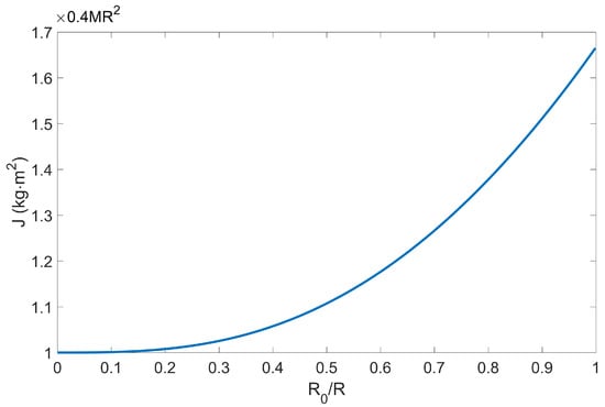
Figure 1.
MOI of a hollow sphere with a fixed amount of mass.
Eventually, the rotor is designed as a hollow sphere, consisting of three layers of metals, as shown in Figure 2. The inner layer is made of steel, which is used to form the magnetic circuits with the stator cores through the air gap. The surface of the steel is electroplated with a copper film, forming the middle layer, which is used to raise the conductivity and enlarge the electromagnet torque induced by the eddy currents on the surface of the rotor. Additionally, to prevent the copper from oxidation and leading to conductivity reduction, a thin nickel layer is deposited on the copper by electroplating, forming the outer layer.
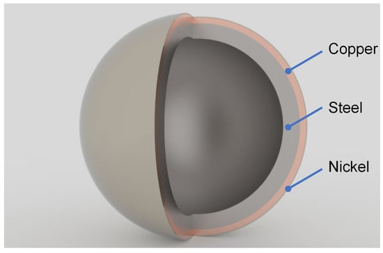
Figure 2.
Multilayer spherical shell.
2.2. Stator
The stator of the reaction sphere is fixed with the spacecraft body, which consists of the curved stators and the electromagnets. They are responsible for rotation motion and magnetic suspension respectively. The curved cores and the electromagnet cores are used to conduct the magnetic flux generated by the stator coils. To meet the requirement of generating tri-axial torques, the stator must be designed as a spherically symmetric structure. As shown in Figure 3, the stator of the reaction is formed by three circles that are orthogonal to each other. Each circle is composed of 4 curved cores and enables the rotor to rotate about one certain axis. The output torque about any axis can be realized by combining the torques generated by the three circles. On the other hand, in order to eliminate the mechanical friction and extend its working life, six electromagnets are set in the position of the six intersection of three circles to get the spherical rotor magnetically levitated in the center of the stator.
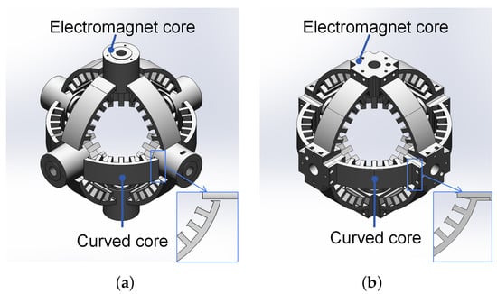
Figure 3.
Structural design of the stator cores: (a) original design and (b) improved design.
In the original design with round-shape electromagnet cores, as shown in Figure 3a, only five complete teeth on the curve iron-core are functional, while the two teeth near the side of the curve stator are not. The notches are formed by connecting three pieces of iron-core curve stator to form one complete stator circle. It causes non-uniformity eddy current and magnetic field induced along the stator circle. To reduce such effect and get the stator magnetic fields utilized in a more sufficient way, the structure of the electromagnet cores are revised to be the cross-shape. In this way, the curved iron-core and electromagnet core can be assembled together and so that two extra teeth on the side are functional, as shown in Figure 3b.
2.3. Winding
For the convenience of speed adjustment and the feature of self-starting, the stator coils are rolled as three-phase windings. In order to generate the equivalent tri-axial torques, the stator should be symmetric in both mechanical and electrical designs. Since the uniaxial plane is divided into four equal parts, as shown in Figure 4, 12 coils are missing in each circle due to the occupation of the electromagnets. All in all, 1/3 of the driving coils are replaced by electromagnet coils.
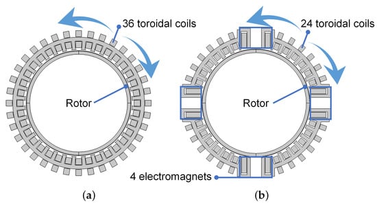
Figure 4.
Section diagram of the reaction sphere (one-DOF): (a) 36 toroidal coils. (b) 24 toroidal coils and 4 electromagnet coils.
As can be seen in Figure 5a,c, the three-phase windings come to two types, 6-pole and 4-pole. 6-pole windings can be regarded as removing 12 coils directly from the complete set of three-phase windings, which does not make any adjustment of the rest windings. As for 4-pole windings, the phase of next coil starts right from the end of the last one so that the windings on the four curved cores can achieve consistency.
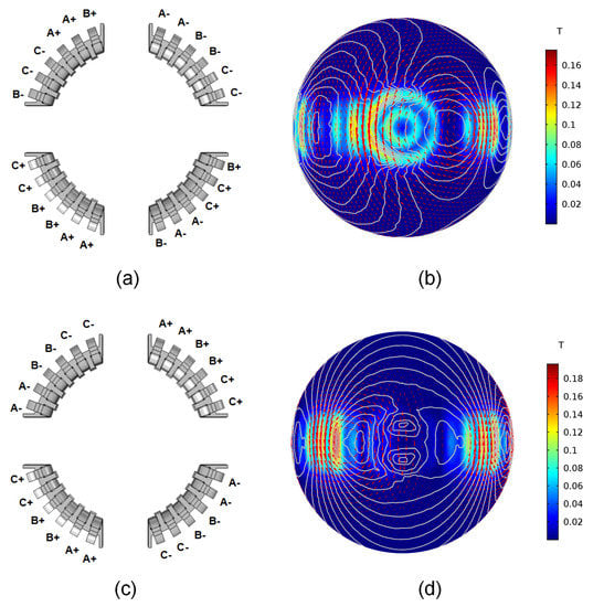
Figure 5.
Winding mode and simulation of magnetic field and induced currents on the surface of the rotor: (a) 6-pole scheme. (b) Simulated distribution of 6-pole scheme. (c) 4-pole scheme. (d) Simulated distribution of 4-pole scheme.
With finite element method (FEM) modeling in COMSOL Multiphysics 5.3, the fields and currents distribution on the surface of the rotor can be visually analyzed. As shown in Figure 5b,d, the gray lines stand for the magnetic line of force, the red arrows refer to the induced currents and the surface colors refer to the radius magnetic flux density. In this simulation, copper thickness, steel thickness, ampere turns, tooth thickness and tooth width are set as 0.3 mm, 3 mm, 2.4 kA, 3 mm and 25 mm respectively. In this case, the driving torques of the 6-pole arrangement and 4-pole arrangement are 33.8 mNm and 27.0 mNm, where the former is 1.25 times larger than the latter. However, it can be seen that, in 6-pole scheme, two poles are much larger than the rest four and the field distortions in the regions that face the electromagnets are serious. Also, it induces an asymmetric distribution of eddy currents by the adjacent curved stators. These features increase the difficulty of multi-DOF motion control of this 6-pole reaction sphere. Furthermore, from the radius magnetic flux density in Figure 5b,d, it can be seen that, in 6-pole arrangement it is the electromagnet cores that mainly contribute to the driving torque, while in 4-pole arrangement it is the curved cores that mainly contribute to the driving torque. The 4-pole arrangement makes the curved cores better exploited. Additionally, the case without electromagnets cores is simulated, where the torque of 4-pole scheme declines from 27 mNm to 18.4 mNm, and the torque of 6-pole scheme declines from 33.8 mNm to 9.89 mNm. This phenomenon reflects the generated torque is stronger dependent on the electromagnet cores in 6-pole scheme. The flux generated by this 6-pole arrangement mainly passes through the inner core of the electromagnets, which can interfere the magnetic suspension and increase the risk of magnetic saturation.
In summary, while reducing the output torque (20% reduction rate in case of the Figure 5), 4-pole arrangement brings the benefits in three aspects compared with 6-pole arrangement. Firstly, it generates a more uniform distribution of magnetic field and eddy currents on the surface of the rotor. Secondly, it is beneficial for larger angular momentum storage due to its higher synchronous speed with the same power frequency. Thirdly, it reduces the risk of magnetic saturation when the curved inductors and electromagnets are working at the same time. Thus, the 4-pole scheme is adopted for the reaction sphere windings.
3. Analytical Model
This section analyzes the magnetic fields on the surface of the rotor, which leads to the solution to electromagnetic driving torque. This also allows us to analyze the generated torque with respect to some of the key design parameters, such as number of poles. Several simplifications are made here. (1) The magnetic permeability of the rotor core is infinite. Thus, no magnetic saturation is encountered. (2) The length of air-gap is evenly distributed. (3) Displacement currents are neglected. Thus, the current law are simplified as Ampere’s law.
Generally speaking, the magnetic flux density can be calculated by computing the curl of magnetic vector potential. In spherical coordinates , the formula can be expressed as
where , and refer to the unit vectors, , and refer to components of the vector potential in spherical coordinate system.
The general torque of the reaction sphere is the vector summation of 3 torques , , and generated by 3 identical circles of the stator.
The following analysis will take torque about z-axis for example. It is the longitudinal magnetomotive force (mmf) that induces the z-axis rotating magnetic field, in which case . Therefore, the magnetic flux density can be simplified as
In spherical coordinate system, by Ampere’s law ,
In this case, only those currents flowing in -direction induce torque about z-axis,
Express the magnetic potential written in complex form [27], where is the angular frequency of input currents, j is the imaginary unit. Then,
Combine (4) and (5), the differential equation for magnetic field distribution on the surface of the rotor is obtained as
To make (6) solvable, apply the the method of separation of variables as
With high-order time and space harmonics neglected, it is assumed that only has the first mmf space harmonic. In this way,
where p is the number of pair pole. The analytical solution to (9) is given as
Set . Then, (11) are transformed to modified Bessel’s Equation (12) [28],
where . The analytical solution to (12) is as follows:
where and are the two linearly independent solutions to the modified Bessel’s Equation [28]:
Subsequently, the magnetic flux density can be calculated through (15), with boundary conditions of and , for continuity, where is the radius of rotor outer surface and is the radius of rotor inner surface. The nickel layer is neglected because it is much thinner than copper layer and steel layer.
Based on the flux density distribution, the driving torque can be evaluated by Lorentz forces induced by eddy currents on the copper layer of the rotor. The electromagnetic torque arising from the rotor steel is negligible [27].
In case of proposed design, 16 of the 36 teeth in circle are occupied by 4 electromagnets (see Figure 4a). After structural optimization (see Figure 3b), each side tooth of these curved cores can be approximated as a half tooth concerning its combination with the electromagnet core. This helps form 4 equivalent teeth. So the output torque generated by the four curved inductors is 2/3 of the complete electromagnetic torque. Then, substitute (5), (7) and (10) into (16),
From (20), it can be seen that higher electrical conductivity and pole numbers can enhance the output torque. So it is reasonable to adopt high conductivity materials like copper as the outer layer of the rotor. Also, the torque is expected to be reduced when choosing the 4-pole winding instead of 6-pole winding. To raise the output torque, the design parameters like tooth thickness and tooth width are required to be optimized in developing the prototypes. However, the analytical torque model (20) does not include these parameters. To authors’ best knowledge, all the proposed analytical fields and torque models of inductive reaction spheres are developed based on the assumptions that the stator is slotless [27,29,30,31]. Otherwise, the differential equation will be too complex to find an analytical solution. Due to the nonlinear dependency of design parameters and the 3-D fields distribution, it is too complicated to derive a purely analytical torque model if the stator contains slots. Hence, data-based modeling technique is used to predict the output torque with design parameters considered to be optimized in the following section.
4. Torque Density Optimization
4.1. Data-Based Torque Model
In this optimization, by dimension constraints, the air gap length is fixed as 1 mm, the outside diameter of the rotor is fixed as 99 mm and the outside diameter of the stator is fixed as 123 mm. The goal is to raise the output torque under the constraints of mass and MOI by searching the optimal tooth thickness (S), tooth width (B), ampere turns (), copper thickness () and steel thickness () as shown in Figure 6. Due to the time consuming of FEM calculation, the comprehensive design is not practical. Thus, Taguchi design of five factors five levels is adopted to select the representative samples data necessary for building learning models as shown in Table 1 [32]. Consider the overall size and the process feature, the ranges of , , , S and B are set as 0.1–0.5 mm, 1–5 mm, 1.5–2.7 kA, 2–4 mm and 20–30 mm respectively.
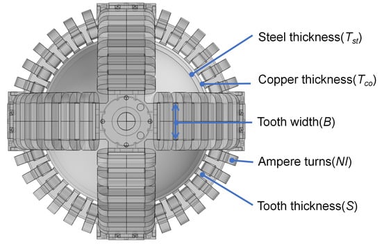
Figure 6.
Design parameters to be optimized.

Table 1.
The parameters of sample space.
Eight groups of the Taguchi design form the 200 trials with no repeated experiments. Each group consists of 25 samples, which selects the representative samples from the whole parameter space by following the two rules. (1) The value in column has the same number of occurrences. (2) Any pair of values between two arbitrary columns have the same number of occurrences. Subsequently, of all the eight groups, seven groups are used to train the learning model and the rest one is used to test the prediction performance of the model. The output torque is obtained by FEM calculation. To reveal the uneven distribution of the air gap length and raise the accuracy of the calculation, 3D FEM is adopted instead of 2D one. The whole mass is estimated by the CAD model volume and its density. The materials used in FEM simulation are listed in Table 2. The rated current is set to 1.4 A. The power source is 50 Hz.
Table 2.
Material components of FEM and lab prototype.
The various parameters of the inductive RS have high nonlinear relationships due to the 3-D field distribution and electromagnetic conversion. Fitting neural network (FNN) has the strength of realizing the complex non-linear mapping between the input and the output. So it is suitable for solving the problem of inductive RS torque prediction with complicated internal mechanism. Due to the large calculation and time consumption of 3D finite element simulation, obtaining a large number of training samples are not practical. Support vector machines (SVM) fit well for the small or medium size of training samples. It determines the final results with only a few support vectors. The major redundant samples are eliminated after training. Random forest (RF) can handle data with many features and have high training speed with independent decision trees. This fits the efficient multi-variable optimization of the inductive RS. Also, it can reduce the risk of over-fitting by increasing tree numbers. It is hard to give strict conclusion of application domains for the three methods. In practice, we choose the appropriate method according to the specific situation.
To enhance the prediction performance, the tree numbers of RF, the hidden layer size of the FNN and parameters of the SVM are optimized. As shown in Figure 7, increasing the number of trees generally improves the accuracy of RF and prediction tends to be stable. It reaches the highest average accuracy of 0.0022 Nm with 44 trees. As for fitting neural networks, it takes a row vector of N hidden layer sizes, and a BP training function, and returns a feed-forward neural network with N + 1 layers. Theoretically, multi-layer fitting neural networks can fit any finite input-output relationship well given enough hidden neurons. However, the risk of over fitting increases with the increase of hidden neurons, where it may fit well for the training data but badly for the test data. Thus, the hidden layers should be chosen properly. As shown in the second figure of Figure 7, it reaches the highest average accuracy of 0.0011 Nm with 10 hidden layers. As for SVM, the radial basis function is set as the kernel function considering the nonlinearity of the torque model. The SVM parameter cost (c), radial basis function parameter (g) and epsilon in loss function (p) are chosen to be optimized. This optimization is carried out by genetic algorithms. To avoid over fitting, c, g and p are constrained within 100, 100 and 1 respectively. It shows that the SVM prediction model reaches the highest average accuracy of 0.00093 Nm when c p and g are 70.716, 0.019 and 0.066 respectively.
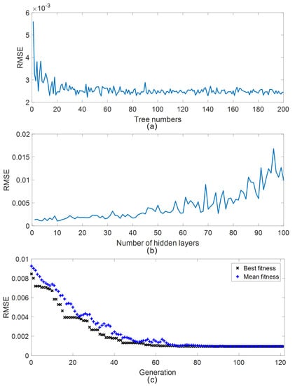
Figure 7.
Data-based models parameters optimization: (a) RF regression with increasing trees, best root-mean-square error (RMSE) of 0.0022 Nm with 44 trees. (b) NN regression with increasing hidden layers, best RMSE of 0.0011 Nm with 10 hidden layers. (c) SVM regression with genetic algorithm optimizing parameters, best RMSE of 0.0009 Nm with c (70.716), p (0.019) and g (0.066).
All in all, the regression results of the test set show that the SVM model achieves the least RMSE over the other two in the case of small-sample database. The optimal predictions by RF, FNN and SVM are shown in Figure 8a, with these test samples arranged by Taguchi design of five factors five levels. Figure 8b shows the prediction errors of RF, FNN and SVM for each sample. It can be seen that the SVM torque model has a stable prediction, with all errors restricted in 2 mNm. Thus, the SVM model is chosen to be the objective function of the optimization in next subsection.
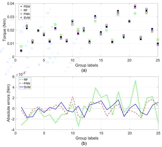
Figure 8.
RF, FNN and SVM models prediction performance with test data: (a) torque predictions and (b) absolute errors.
4.2. Design Parameters Optimization
The reaction sphere design parameters optimization is a multi-parameter optimization problem with constraints. The objective function is the SVM torque prediction model established above. The constraints include the box constraints, linear inequality constraints and nonlinear inequality constraints. The box constraints (22)–(26) are set to be consistent with the range of the sample spaces shown in Table 1. The linear inequality constraints are considered between coil turns, tooth thickness and tooth width: The coil turns and tooth thickness are limited by the tooth pitch (27); The coil turns and tooth width are limited by the fixed stator arc length (28). The parameters of the linear inequality constraints are validated by the lab possessed parts shown in Figure 9. The nonlinear inequality constraints consider the application in micro spacecrafts: the MOI of the rotor is larger than 0.001 kg·m (29) and the whole mass of the actuator is no more than 3 kg (30).
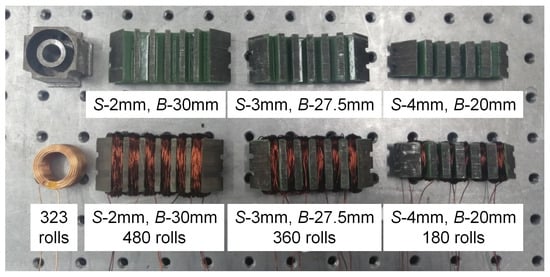
Figure 9.
Parts of the reaction sphere prototype for constraints and masses validation.
The mass function M evaluates mass of the whole actuator, consisting of rotor, stator core, toroidal winding and electromagnets. The mass of the rotor and stator core is estimated by their measured volume of the digital model and their corresponding densities. The mass of the toroidal winding is calculated by the product of turn number and mass of each turn. The mass of the electromagnets is a constant, which is weighed with prototypes. Several sample components are selected to validate its accuracy as shown in Table 3. Due to the insulating coating, the mass test results of the curved cores are slightly larger than the estimated ones.
Table 3.
Mass estimation and experimental validation.
Based on the analysis above, the mathematical description of the optimization problem can be expressed as:
This constrained optimization is carried out by interior point methods on MATLAB2016a optimization toolbox, with parameter setting as follows: function tolerance and constraints tolerance: , max iterations: 1000. Inner max iterations: 100, relative tolerance: . The optimization results are listed in Table 4. The iteration process is shown in Figure 10. The final , , , S, B for developed 4-pole prototype are rounded as 0.5 mm, 2.4 mm, 2.688 kA, 3 mm and 27.5 mm respectively. The driving torque is 0.0371 Nm (FEM) with the whole mass of 3 kg and MOI of 0.001 kg·m.
Table 4.
Constrained optimization results by interior point methods.
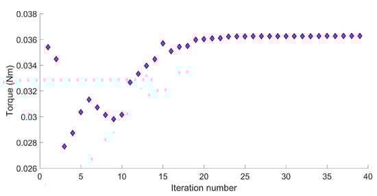
Figure 10.
Design parameters optimization by interior point method for better output torque.
5. Feasibility Test with Lab Prototypes
To validate the feasibility of the proposed design, the experimental setup is developed to test the speed performance of the lab prototypes, which is composed of converters, DC power supply, reaction sphere actuators, controllers and amplifiers as shown in Figure 11. The three converters are responsible for driving the reaction sphere actuators in the three orthogonal axis respectively. The DC power supply provides direct currents for amplifiers and controllers for magnetic levitation control.
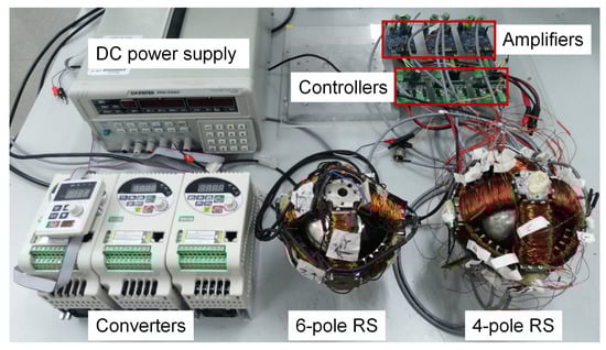
Figure 11.
Experimental setup for driving the 4-pole reaction sphere and 6-pole reaction sphere under magnetic levitation.
In this magnetic levitation system, to get the feedback position signal in the closed-loop control, an eddy current displacement sensor made of tiny coils is placed at the center of each electromagnet. These sensors provide the signal of air gap distance to the controller. From here, a negative feedback control loop is set up by two serial-link PD controller to regulate the levitation distance. Specifically, the controller uses STM32F051K6T6 (Suzhou Joint-Tech Mechanical and Electrical Technology Co., LTD, Suzhou, China), which collects the signal of eddy current displacement sensors and generates PWM signal to drive the power amplifier. Each driver amplifies the control signal and drives the two electromagnetic coils on the same axis. What should be mentioned is that the electromagnets about Z-axis need to overcome the gravity of the rotor. They require higher currents compared with the counterparts about the other two axes. A 4-pole reaction sphere prototype and a 6-pole reaction sphere prototype are developed to test the speed performance with the same controllers and drivers. A binary painting strategy for speed measurement is presented as shown in Figure 12. The four silvery white circles on the surface of the rotor are located on the four vertexes of a tetrahedron. In case of measuring the X, Y and Z rotational speed, the laser focus will come across the high reflective areas, which is the nickel protection layer shown in Figure 2, 3 times when the rotor turn around once. Therefore, the output speed can be estimated as the one-third of counts per minute. The frequency of AC is set to 60 Hz in X, Y and Z axis respectively of the 4-pole reaction sphere prototype and in X and Y axis respectively of the 6-pole reaction sphere prototype. The Z axis of the 6-pole reaction sphere is set to 54 Hz, for higher frequency cannot generate a stable rotation with its significantly increasing vibration. This results from the parts manufacturing and assembling error, as well as the dynamical stability of the sphere about Z-axis rotation under gravity force for 6-pole RS, probably due to its unequal pole. The speed test results are listed in Table 5. It is shown that the 4-pole reaction sphere prototype has the maximum of 775 rpm, 791 rpm and 795 rpm in X, Y and Z axis respectively, which obtains a better speed performance over the 6-pole one as predicted. As for speed uncertainties, the 4-pole prototype shows a relatively smaller fluctuations, which may benefit from the uniform fields distributions.
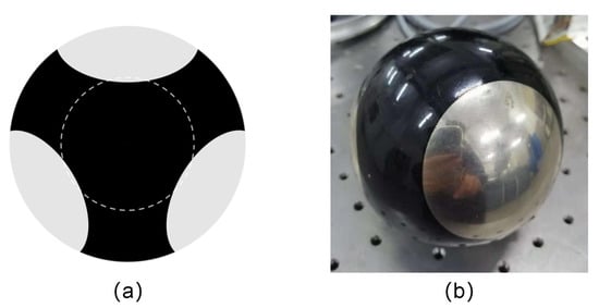
Figure 12.
Spherical rotor with black painting for speed counts: (a) diagram and (b) prototype.
Table 5.
Maximum speed of the four-pole reaction sphere prototype and the six-pole reaction sphere prototype.
The speed control experiment is not so successful. The tested output speed is much less than the synchronization speed (1800 rpm @ 60 Hz). When the frequency is over 60 Hz, the increasing vibration leads to the mechanical collision between the rotor and the stator. One reason lies in the quality of the prototypes. The magnetic levitation demands for the high precision of parts processing and assembling, which is not well guaranteed in the developed prototypes. This results in the non-unique performance in different axes, which is particularly evident between Z axis and the other two axes in the 6-pole prototype.
A more essential reason lies in a drawback of the proposed design: When producing the driving torque, the rotation windings on the curved inductor will generate an extra thrust in the meantime. This extra thrust will push the electromagnets to generate the flux and attract the rotor to be back in the center of the stator. Then, additional damping torques will be induced by the interaction between the rotating rotor and the electromagnets flux, which leads to speed reduction.
6. Conclusions
This paper presents the new design, modeling and parameter optimization methods of a magnetically levitated inductive reaction sphere. It provides a simple, low-cost and miniaturized solution to spacecraft attitude control via momentum exchange. The compact design of electromagnets and curved inductors has the dimensional ratio of 1:1.4 between the rotor and the stator assembly. The simplified, analytical driving torque model is derived based on Ampere’s law and separation of variables, showing that the conductivity of the rotor outer layer and pole number of the stator fields contribute to the driving torque. To raise the agility of attitude adjustment of satellites, it is crucial to improve the torque density of this 4-pole inductive RS besides introducing slots in the iron-core curve stator. Here, its curved inductors and electromagnets are redesigned as the cross-shape, allowing two more slots near the notches of the curve stator to be functional. This also improves the uniformity of the induced eddy current and magnetic field along the stator circle. As the full analytical torque model is not available for inductive RS with slotted curve stators, a constrained optimization problem is formulated to maximize the output torque. In addition, the design parameters are efficiently solved by SVM with only small volume of training data. The lab prototype is developed for feasibility test. It shows that the optimized RS can rotate over 700 rpm in X, Y and Z axis with the angular momentum of 0.08 kg·m/s.
Small volume and small mass are two essential issues in reaction spheres design. The proposed compact design enables the developed prototype to have the rotor mass of 0.66 kg and the whole assembly of 3 kg under the dimension constraints of 136 mm × 136 mm × 136 mm. The necessary angular momentum of the actuator is expected to be within 0.1–1 kg·m/s for actual micro-spacecraft (10–100 kg) attitude control [33,34], and the practical design target is set as 0.4 kg·m/s. If we maintain the design parameters in this paper, the rotor has to spin about 3800 rpm to achieve this, demanding a high level of dynamic balance. Due to the current restraint of motor drivers and the error during part fabrication and assembly, it is not practical to realize such speed with our prototypes. A more practical way is to increase both the output speed and the mass of the steel layer of the rotor appropriately. For example, we can achieve the angular momentum of 0.4 kg·m/s by increasing the speed to 1500 rpm and the steel thickness of the hollow sphere to 9.5 mm respectively. Remarkably, the design and optimization methods proposed in this paper are still applicable in the practical reaction sphere development.
Author Contributions
L.Y. derived the electromagnetic modeling, optimization method and prepared the manuscript; J.Z. and J.C. proposed the original inductive RS design; S.-L.C. advised the theoretical study, designed the experiments and refined the manuscript; Y.L. and L.Y. assembled the prototypes and carried out experimental test; C.Z. and G.Y. supervised the research throughout.
Funding
This research was funded by Zhejiang provincial public welfare research program(Y19E070003, LGG18E070007) and the innovation team of key components and key technology for the new generation robot(2016B10016).
Conflicts of Interest
The authors declare no conflict of interest.
Appendix A. Proof: (A1) is a Monotonically Increasing Function
The MOI of a hollow and uniform sphere is
where is a variable, R and M are constants, , R, M∈. Take logarithms on both sides of (A1),
Take the derivative of (A2) with respect to , it yields
Set , so . In addition, . In this way, for , . This yields .
This concludes is monotonically increasing when . Additionally, , , .
References
- Maini, A.K.; Agrawal, V. Satellite Technology: Principles and Applications; John Wiley & Sons: New York, NY, USA, 2011. [Google Scholar]
- Ormsby, R.D. Capabilities and limitations of reaction spheres for attitude control. ARS J. 1961, 31, 808–812. [Google Scholar] [CrossRef]
- Haeussermann, W. The Spherical Control Motor for Three Axis Attitude Control of Space Vehicles; NASA TM X-50071; NASA: Greenbelt, MD, USA, 1959.
- Haeussermann, W. Space Vehicle Attitude Control Mechanism. U.S. Patent 3,017,777, 23 June 1962. [Google Scholar]
- Bitterly, J.G. Flywheel technology: Past, present, and 21st century projections. IEEE Aerosp. Electron. Syst. Mag. 1998, 13, 13–16. [Google Scholar] [CrossRef]
- Kurokawa, H. A Geometric Study of Single Gimbal Control Moment Gyros; Report of Mechanical Engineering Laboratory, no. 175; Agency of Industrial Technology and Science: Tokyo, Japan, 1998.
- Stagmer, E. Reaction Sphere for Stabilization and Control in Three Axes. U.S. Patent 9,475,592, 25 October 2016. [Google Scholar]
- Rossini, L. Electromagnetic mOdeling and Control Aspects of a Reaction Sphere for Satellite Attitude Control. Ph.D. Thesis, EPFL, Lausanne, Switzerland, 2014. [Google Scholar]
- Craveiro, A.A.; Sequeira, J.S. Reaction sphere actuator. IFAC-PapersOnLine 2016, 49, 212–217. [Google Scholar] [CrossRef]
- Zhang, M.; Zhu, Y.; Chen, A.L.; Yang, K.M.; Cheng, R. A Maglev Reaction Sphere Driven by Magnetic Wheels. CN Patent 105207430 A, 30 December 2015. [Google Scholar]
- Keshtkar, S.; Moreno, J.A.; Kojima, H.; Hernández, E. Design concept and development of a new spherical attitude stabilizer for small satellites. IEEE Access 2018, 6, 57353–57365. [Google Scholar] [CrossRef]
- Takehana, R.; Paku, H.; Uchiyama, K. Attitude control of satellite with a spherical rotor using two-degree-of-freedom controller. In Proceedings of the 2016 7th IEEE International Conference on Mechanical and Aerospace Engineering (ICMAE), London, UK, 18–20 July 2016; pp. 352–357. [Google Scholar]
- Hollis, R.L., Jr.; Kumagai, M. Spherical Induction Motor. U.S. Patent 9,853,528, 26 December 2017. [Google Scholar]
- Fan, D.; Chun, C.S.; He, Y.; Song, J.; Zhang, N. Magnetization Suspension Inductive Reaction Sphere. CN Patent 105,775,169, 20 July 2016. [Google Scholar]
- Isely, W.H. Magnetically Supported and Torqued Momentum Reaction Sphere. U.S. Patent 4,611,863, 16 September 1986. [Google Scholar]
- Wampler-Doty, M.P.; Doty, J. A reaction sphere for high performance attitude control. In Proceedings of the 8th Annual CubeSat Developers’ Workshop, San Luis Obispo, CA, USA, 20–22 April 2011. [Google Scholar]
- Iwakura, A.; Tsuda, S.-I.; Tsuda, Y. Feasibility study on three dimensional reaction wheel. Proc. Sch. Sci. Tokai Univ. Ser. 2008, 33, 51–57. [Google Scholar]
- Kim, D.-K.; Yoon, H.; Kang, W.-Y.; Kim, Y.-B.; Choi, H.-T. Development of a spherical reaction wheel actuator using electromagnetic induction. Aerosp. Sci. Technol. 2014, 39, 86–94. [Google Scholar] [CrossRef]
- Kumagai, M.; Hollis, R.L. Development and control of a three dof spherical induction motor. In Proceedings of the 2013 IEEE International Conference on Robotics and Automation, Karlsruhe, Germany, 6–10 May 2013; pp. 1528–1533. [Google Scholar]
- Chételat, O. Torquer Apparatus. U.S. Patent 8,164,294, 24 April 2012. [Google Scholar]
- Chabot, J.; Schaub, H. Spherical magnetic dipole actuator for spacecraft attitude control. J. Guid. Control. Dyn. 2016, 39, 911–915. [Google Scholar] [CrossRef]
- Zhou, L.; Nejad, M.I.; Trumper, D.L. Hysteresis Motor Driven One Axis Magnetically Suspended Reaction Sphere; American Society for Precision Engineering: Raleigh, NC, USA, 2014. [Google Scholar]
- Zhou, L.; Nejad, M.I.; Trumper, D.L. One-axis hysteresis motor driven magnetically suspended reaction sphere. Mechatronics 2017, 42, 69–80. [Google Scholar] [CrossRef]
- Liu, J. Structural Design and Three-Dimensional Magnetic Field Analysis of Magnetic Levitation Switched Reluctance Spherical Motor. Master’s Thesis, Yangzhou University, Yangzhou, China, 2011. [Google Scholar]
- Paku, H.; Uchiyama, K. Satellite attitude control system using a spherical reaction wheel. In Applied Mechanics and Materials; Trans Tech Publ: Zurich, Switzerland, 2015; Volume 798, pp. 256–260. [Google Scholar]
- Mashimo, T.; Awaga, K.; Toyama, S. Development of a spherical ultrasonic motor with an attitude sensing system using optical fibers. In Proceedings of the 2007 IEEE International Conference on Robotics and Automation, Roma, Italy, 10–14 April 2007; pp. 4466–4471. [Google Scholar]
- Zhu, L.; Guo, J.; Gill, E. Analytical field and torque analysis of a reaction sphere. IEEE Trans. Magn. 2018, 54, 1–11. [Google Scholar] [CrossRef]
- Stegun, A. Handbook of Mathematical Functions. US Government Printing Office, October 1973. Available online: http://people.math.sfu.ca/~cbm/aands/page_374.htm (accessed on 14 January 2019).
- Spałek, D. Spherical Induction Motor with Anisotropic Rotor-Analytical Solutions for Electromagnetic Field Distribution, Electromagnetic Torques and Power Losses. 2007. Available online: http://www.compumag.org/jsite/images/stories/TEAM/problem34.pdf (accessed on 15 November 2018).
- Davey, K.; Vachtsevanos, G.; Powers, R. The analysis of fields and torques in spherical induction motors. IEEE Trans. Magn. 1987, 23, 273–282. [Google Scholar] [CrossRef]
- Davey, K.; Vachtsevanos, G.; Powers, R. Analysis of a spherical induction motor. Electr. Mach. Power Syst. 1987, 12, 206–223. [Google Scholar] [CrossRef]
- Mark, A. Tschopp, DOE with MATLAB. Available online: https://icme.hpc.msstate.edu/mediawiki/index.php/DOE_with_MATLAB_3 (accessed on 8 October 2018).
- Scharfe, M.; Roschke, T.; Bindl, E.; Blonski, D. Design and development of a compact magnetic bearing momentum wheel for micro and small satellites. In Proceedings of the 15th Annual/USU Conference on Small Satellites, Logan, UT, USA, 13–16 August 2001. [Google Scholar]
- Grillmayer, G.; Falke, A.; Roeser, H.-P. Technology demonstration with the micro-satellite flying la’pt op. In Small Satellites for Earth Observation: Selected, Proceedings of the 5th International Symposium of the International Academy of Astronautics, Berlin, Germany, 4–8 April 2005; Walter de Gruyter: Berlin, Germany, 2011; p. 419. [Google Scholar]
© 2019 by the authors. Licensee MDPI, Basel, Switzerland. This article is an open access article distributed under the terms and conditions of the Creative Commons Attribution (CC BY) license (http://creativecommons.org/licenses/by/4.0/).