Abstract
When considering implementation of shallow geothermal energy as a renewable source for heating and cooling of buildings, special care should be taken in the hydraulic design of the borehole heat exchanger system. Laminar flow can occur in pipes due to the usage of glycol mixtures at low temperature or inadequate flow rates. This can lead to lower heat extraction and rejection rates of the exchanger because of higher thermal resistance. Furthermore, by increasing the flow rate to achieve turbulent flow and satisfactory heat transfer rate can lead to an increase in the pressure drop of the system and oversizing of the circulation pump which leads to impairment of the seasonal coefficient of performance at the heat pump. The most frequently used borehole heat exchanger system in Europe is a double-loop pipe system with a smooth inner wall. Lately, development is focused on the implementation of a different configuration as well as with ribbed inner walls which ensures turbulent flow in the system, even at lower flow rates. At a location in Zagreb, standard and extended thermal response tests were conducted on three different heat exchanger configurations in the same geological environment. With a standard TRT test, thermogeological properties of the ground and thermal resistance of the borehole were determined for each smooth or turbulator pipe configuration. On the other hand, extended Steady-State Thermal Response Step Test (TRST) incorporates a series of power steps to determine borehole extraction rates at the defined steady-state heat transfer conditions of 0/−3 °C. When comparing most common exchanger, 2U-loop D32 smooth pipe, with novel 1U-loop D45 ribbed pipe, an increase in heat extraction of 6.5% can be observed. Also, when the same comparison is made with novel 2U-loop D32 ribbed pipe, an increase of 18.7% is achieved. Overall results show that heat exchangers with ribbed inner pipe wall have advantages over classic double-loop smooth pipe designs, in terms of greater steady-state heat extraction rate and more favorable hydraulic conditions.
1. Introduction and Literature Overview
The interest of using shallow geothermal energy via borehole heat exchangers and heat pump systems is on the rise in the last decades. In order to optimize the system and to determine its performance, thermal response tests are usually performed on heat exchangers. The most common pipe configurations installed in boreholes are double-U (2U) or single-U (1U) ones. Therefore, these configurations, with different diameters and inside pipe lining, were chosen to compare their thermogeological and hydraulic parameters and the impact they have on heat rejection/extraction rates.
The thermal response test (TRT) is a standard in-situ method of evaluating thermogeological properties of the ground, especially the effective ground thermal conductivity coefficient. The procedure consists of circulating a heated fluid through a borehole heat exchanger (BHE), which causes heat rejection to the ground. With the inversion of collected data, the temperature response in the case of heat extraction could be obtained. With such an analysis, the optimization of borehole heat exchanger fields and heat pump systems is possible. Even though there is already extensive research on the implementation of TRT data on optimizing BHE systems, there is space to improve and implement the research, especially when it comes to hydraulic setting.
In the last decade alone there has been a rise of research when it comes to optimizing the BHE system, by observing the influence of various geometrical settings, hydraulic settings and heat rates on the overall performance. Various studies have focused on a better understanding and more precise estimation of effective thermal conductivity and borehole thermal resistance [1,2,3,4] as important parameters when exploiting the shallow geothermal resource. Current methods of determining the average fluid temperature within BHE, as well as the influence of various measuring methods during TRT, on the final determination of thermal properties are also available [5,6,7]. With newly established data interpretation of time derivative of fluid temperature, measured during the first few hours of TRT operation, it was shown that the duration of the test could be shortened significantly, while the values of effective thermal conductivity can still be estimated within the 10% margin of error [8]. A similar result of only a 10% value variation of thermal conductivity, can be obtained if the data are obtained from the falloff temperature decline when using a method based on the analogy between TRT and petroleum well testing [9]. The origin of both procedures lies in the same diffusivity differential equation, with solutions for heat conduction or pressure transient analysis during radial flow in porous media. The use of the step thermal response test showed that it is suitable when determining heat rejection/extraction rates, useful for design optimization of the BHE field [3,10]. The influence of the groundwater advection on the efficiency and modelling of the ground BHE is detailed, with the study of its relationship with the modeling of the BHE field [7,11,12,13]. Aside from the borehole distance and the geometrical arrangement of the borehole field, research was done on the comparison of a geometrical setting of the exchanger pipes themselves.
Some recent studies deal with a comparison of various borehole heat exchanger types, constructions and overall efficiency of the ground source heat pump systems [1,14,15,16]. When comparing single U and double U tubes, it was shown that the double U exchangers show better performance, with reduced thermal resistance values [17]. There is also a development of various other BHEs setup, other than classic 1U and 2U; such are coaxial, helical and oval pipes and the use of the so-called fins or grooves within the pipe itself [1,18,19,20]. Among the first to study the use of the ribbed inner wall or micro fins, was Acuña [21]. Fins enable higher heat transfer rates due to the larger heat transfer surface, which improves the thermal performance of the exchanger pipe. Additionally, the research showed lower pressure drop values, in comparison with other tested BHEs. Also, the function of such a configuration is to maintain turbulent fluid flow, even in situations where the Reynolds number suggests a laminar type fluid flow. This results in lower use of the circulating pump, which in turn affects the operating costs. Since then, models and experiments have been presented on the benefits of using finned pipes, commercially known as TurboCollectorTM [22].
Bouhacina et al. [23] presented two numerical models, which described heat transfer and showed effects when using finned high-density polyethylene (HDPE) 1U pipe. The results were compared with a classic 1U layout with a smooth inner wall pipe. It was concluded that because of the smaller hydraulic diameter the mass flow rate is lower with finned pipes than in smooth pipes. Bae et al. [24] conducted TR tests at the same site on four different BHEs-coaxial, 1U HDPE, 1U HDPE-nano and 1U finned pipes. The results showed that with the improvement of convective heat transfer coefficient and thermal conductivity of pipe, there is a positive influence on overall heat transfer. The borehole thermal resistance of finned pipe was lower than the value of standard HDPE pipe, which was attributed to the fact that the pipe and fluid thermal resistances are reduced.
Therefore, the objective of the paper is to analyze the difference in steady-state heat extraction and rejection rates between different pipe types and geometry of the borehole heat exchangers in the same geological environment in a real project location. The main postulate of the research is the axiom that the novel TurboCollectorTM exchangers, with a ribbed inner wall, have a greater heat extraction and rejection rates due to lower thermal resistance or skin, because of the higher convective heat transfer between fluid and pipe wall. Furthermore, TurboCollectorTM exchangers should have lower pressure drops when turbulent regime is achieved, due to the lower required flow rate in pipes. This hypothesis is crucial to promote this novel design in the case of deeper drilling, where borehole heat exchangers work with more favorable ground temperature due to the positive effect of the geothermal gradient.
2. Theoretical Background
The mathematical model, which describes the extraction or rejection of the heat in the underground, is based on the heat diffusivity equation. Fourier [25] established the model, known as Fourier’s law, and it describes conductive heat transfer in the homogeneous and isotropic environment. When using the cylindrical coordinates, it is expressed as:
where is temperature (°C), is radius (m), is thermal conductivity of the material (W/m °C), is material density (kg/m3), is specific heat (J/kg °C) and is time (s). The expression Kelvin described as thermal diffusivity, α(m2/s). Ingersoll and Zobel [26] describe the Fourier’s law of heat conduction, in solids, with a partial differential equation. Using cylindrical coordinates equation becomes:
There are two main analytical models when solving Equation (2)—line source and cylindrical model. The solutions are dependent on boundary conditions which are taken into account for each of the model. However, in both models, the term is neglected [27]. There are two main approaches when solving for line source model—the infinite line source and finite line source model. The infinite line source model, first described and solved by Lord Kelvin, describes radial heat flow. Carslaw and Jaeger [28] gave a well-known solution for an infinite line source model, used for describing heat extraction or rejection when using borehole heat exchangers. The model assumes that the borehole is an infinite line source in a homogenous and isotropic medium. The solution describes the temperature distribution as a function of time at some distance in relation to the borehole. Since the vertical component is neglected () only radial heat flow is observed. The analytical solution includes the use of exponential integral or its simplified form, with certain constrictions [29,30,31,32]. In the case of heat rejection, the expression for determining temperature response, while performing the thermal response test is:
where is the temperature in function of radius and time (°C), T0 represents the undisturbed ground temperature or the initial temperature (°C), heat power per meter of a borehole (W/m), borehole radius (m) and represents the exponential integral, which can be approximated with natural logarithmic function, in cases when :
where is Euler’s constant with the value of 0.5772. Then, the ultimate expression for heat rejection is:
where is the slope of the line when plotting T vs. ln(t) and it is a standardized principle to obtain average ground thermal conductivity [32].
The finite line source (FLS) model considers the vertical component () as one of the boundary conditions, i.e., the finite length of the heat exchanger is considered. Claesson and Eskilson [27,29,33] gave the solution for the temperature at the borehole wall with FLS model, and in the case of heat rejection it is:
where is the borehole depth (m) and represents the so-called g-function (or Eskilson’s g-function) and it is described as dimensionless temperature response factor. The g-function is calculated as:
The influence of thermal properties of the soil is expressed through the factor (s), which represents the time at which the steady state heat flow is achieved:
In the denominator, this equation contains a value of thermal diffusivity, α, which is assumed from the drilling data. A compressed air system was used to lift the drill cuttings from the well bottom. Based on observed cuttings, the lithological profile was constructed. Based on the catalogue values for a specific type of soil from the lithological profile, ground thermal diffusivity coefficient was estimated. Since this value is usually estimated in practical projects, the method of determining the duration of the transition period can cause a further error in interpretation, especially for highly heterogeneous ground. Much more accurate graph-analytical method, the so-called derivation curve principle, can be implemented to determine the transition from unsteady state heat flow to relevant semi-steady state heat flow regime [9]. Derivation curve constructed from the obtained borehole fluid temperature (y) and TRT elapsed time (x) is derived as:
In order to predict the fluid temperature inside the borehole heat exchanger, the value of borehole thermal resistance must be determined. Well testing in petroleum engineering, when defining formation permeability, is analogous to the classic TRT data analysis when defining thermal conductivity. Considering the similarities in the origin of the equations describing the behavior of pressure in porous medium and heat conduction in solids [9,10], borehole thermal resistance is also equivalent to near-well damage formation or skin factor, , which affects the fluid flow in the well. In thermogeology, the skin factor describes the dimensionless thermal resistance to the heat flow in the borehole.
It depends mainly on pipe configuration, the grout used for cementing of the borehole, as well as on the fluid type and flow properties, and it is expressed as:
where is the duration of power step during semi-steady state and is a temperature difference between initial temperature and temperature at the end of the power step. The analogy between dimensionless skin factor and thermal resistance is expressed as initial temperature rise due to heat flow in the pipe wall and grout, [9,30,31]:
where is the equivalent borehole thermal resistance (°C m/W). A more precise estimation of the thermal conductivity and borehole skin factor is crucial when defining borehole exchanger heat power capacity during long-term operation. In our previous research [9], we showed that implementing the novel steady-state thermal response step test (TRST) is helpful with system optimization. This is especially important for systems with long annual full-load hours of operation when there is a need to establish a relationship between peak load working conditions of the heat pump system and steady-state entering source temperature from the bore field (EST). Also, the latest development of inverter-type geothermal heat pumps requires such an analysis, since the inverter compressor works continuously with modulating power, depending on the outside air temperature curve [34].
The step test is carried out by imposing different heat pulses (heat rejection rates) after a certain period. By using Eskilson’s g-function analysis, it is possible to analytically describe the temperature response of conducted TRST for each step, by superimposing each following step on the steps already conducted [27,29,33]. Therefore, for any arbitrary heat pulse, in case of TRT-heat rejection pulse, the thermal response can be found. The superposition principle suggests that, in the case of performing TRT with three different pulses, the first thermal pulse is imposed during the entire testing period. Each following pulse is superimposed on the previous one. The general expression for the average fluid temperature inside the BHE, for different heat rejection [27] is:
where is borehole fluid mean temperature (°C), and are consequent heat power steps. For example, in the case of three different heat rejection pulses the average temperature of the circulating fluid would be calculated as follows:
First step:
Second step:
Third step:
3. Experimental Site Setting
3.1. Thermogeological and Hydrogeological Setting
The thermal response test was conducted in the city of Zagreb, Croatia, at the location as shown in Figure 1. It also shows a detailed geological map of the city of Zagreb and its surrounding area [35]. The area is located mostly on the Zagreb aquifer system, which is from the Quaternary Age. The aquifer is mostly comprised of Middle and Upper Pleistocene, and Holocene sediments. The location of the BHEs is near the Zagreb aquifer boundary. Up to 110 m, the underground is mostly comprised of gray and brown clay, with some gravel layer at the shallow depth (Figure 2). It is seen from the lithology description, that there is a saturated layer of soil, with a thickness of around 5 m. The project location is near the northern aquifer boundary. From the map of hydraulic conductivity (Figure 2) it can be assessed that the values of hydraulic conductivity at the project location are around 0.3 cm/s. Considering that the Zagreb aquifer is of alluvial origin, and connected to the Sava river water table, the relatively thin layer of saturated gravel and sand at the project site has an insignificant effect on overall heat exchanger capacity.
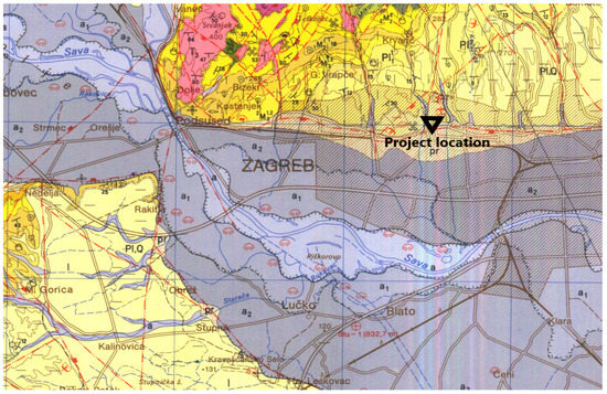
Figure 1.
Detailed geological map with BHEs location and general lithology column of the project site. Legend for geology map: a—aluvium: gravels, sands and clays; a1—the lowest terrace: gravels, sands and clays to a lesser extent; a2—middle terrace: gravels and sands; pr—proluvium: gravels, sands and clays; l—clayey silt; lb—marshy loes: silty clays; Pl,Q—gravels, sands and clays; Pl11—marls, marly clays, sands to a lesser extent, sandstones, gravels and conglomerates (lower pont); 2M31,2—lime marls, sands to a lesser extent, sandstones, gravels and conglomerates (upper panon); 2M22—limestones, sandstones, lime and clayey marls (upper Tortonian).
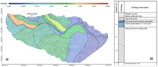
Figure 2.
(a) Map of hydraulic conductivity of Zagreb aquifer [36] and (b) lithology of project location.
3.2. Borehole Heat Exchangers Setup at the Test Site
At the residential project site, three vertical boreholes for heating and cooling purposes were drilled up to 110 m. The drilling diameter of each of the borehole is 152 mm. The project site during the drilling and testing operations is seen in Figure 3a. The thermal response test was carried out on all of the three BHEs with the different geometrical setting, and two pipe arrangements.
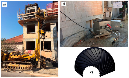
Figure 3.
(a) Drilling of the BHEs; (b) performing the thermal response test; (c) TurboCollectorTM pipe wall.
The BHE-1 is equipped with polyethylene 2U-pipe (D32 mm PE100 SDR11) with a smooth inner wall. Such a design is the most often used borehole heat exchanger in Europe. The second heat exchanger, denoted as BHE-2, is equipped with 2U-pipe (D32 mm PE100 SDR11) with a ribbed inner wall, as shown in Figure 3c. The third borehole, BHE-3, was equipped with a novel TurboCollectorTM 1U-pipe (D45 mm PE100 SDR11).
The total measuring TRT time for each of the boreholes was approximately 120 hours. The three different pipe configurations were used in this project to determine the effect of borehole geometry on overall heating/cooling extraction/rejection rates. Boreholes are placed in typical L-shape, with separation between boreholes of 7 m, as shown in Figure 4.
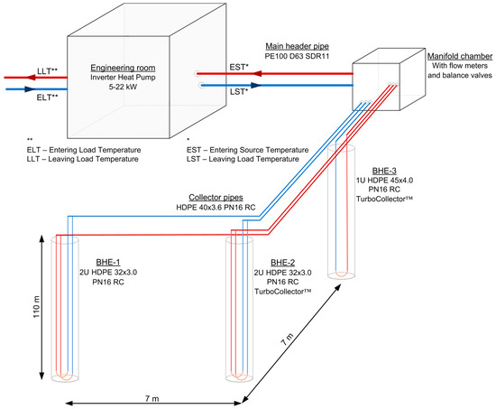
Figure 4.
Simplified schematic of the borehole heat exchangers collector system.
Measurements on three borehole heat exchangers were conducted in October 2018 with a Geocube GC500 TRT apparatus (Precision Geothermal LLC, Marple Plain, MN, USA). The equipment has maximum available electric heater power of 9.0 kW @ 240 V. An internal logger (Onset HOBO H22 energy logger, Onset, Bourne, MA, USA) was set-up to collect inlet and outlet borehole temperature, flow rate, voltage and electric current data in 5-min intervals. Thermocouples (type: resistance temperature detectors-RTD) are placed on inlet and outlet of TRT and have an accuracy of ±0.2 °C ranging from 0 °C to 50 °C. The testing procedure was set up as a classic TRT heat rejection with an initial step of 6.5 kW and a duration of approximately 63 h. Two additional heat steps were introduced afterward, with lower rejection rates where stabilization of borehole temperature was observed. Second heat step of 4.5 kW lasted approximately 24 h, while the third heat step of 2.4 kW was conducted approximately 33 h.
The mean ground temperature along the borehole was measured with TRT apparatus at 15.2 °C, with the fluid flow of 0.45 L/s and no heaters switched on. Borehole fluid is comprised solely out of the water, with viscosity presumed to be around 1 mPa s.
4. Results and Discussion
After switching on the TRT heaters, the average temperature in the borehole heat exchanger begins to grow as a function of ground thermogeological parameters, power step, and borehole thermal resistance. Figure 5 shows recorded average fluid temperature data and power for the first heat step. The entire test was conducted without any significant deviations in the power supply, which interprets highly representative temperature curves.
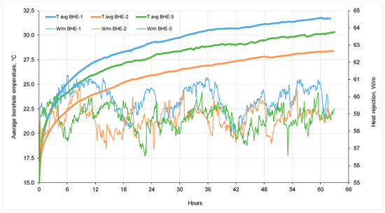
Figure 5.
Recorded average fluid temperatures and a power step for a three borehole heat exchangers during TR testing.
To determine the effective ground thermal conductivity coefficient, it is necessary to plot the average temperature of circulating fluid data vs. natural logarithm of time, ln(t). According to the infinite line source method, initially recorded data during an unsteady state of heat transfer must be excluded from the analysis.
As seen from Figure 6a, using the derivative curve principle and Equation (9) it can be observed that all three BHE layouts shows a transition to semi-steady state heat transfer after roughly the 10th hour, where the derivative dT/dt falls below the value of 0.5 [6].

Figure 6.
Determination of semi-steady state heat flow period (a) and determination of ground heat conductivity (b).
In Figure 6b the standard method is then applied to determine the effective ground thermal conductivity coefficient, by establishing slope of the straight line portion between average borehole temperature and the natural logarithm of time. Using Equation (5) the ground thermal conductivity is then calculated from all of the three tests (data presented in Table 1 and results in Table 2).

Table 1.
Thermal Response Step Test obtained temperature data.
Table 2.
Thermal Response Step Test obtained temperature data.
Figure 7 presents results of the extended thermal response testing. For each of the three boreholes additional fall-off tests were performed, by implementing additional lower heat power values until steady-state heat transfer was achieved for each of the steps (so-called Thermal Response Step Test—TRST). For each of the additional two heat steps, which lasted for 24 and 33 h, steady-state heat flow condition was observed. Such approach can provide confident information about dependency between two variables; borehole outlet fluid steady-state temperature in a function of heat pump evaporater/condenser peak load working conditions. Therefore, for any value of borehole heat rejection or extraction rate, stabilized fluid temperature in the borehole could be determined. This actually means that a borehole heat exchanger can work for a longer period without significant subsequent rise or drop in fluid temperature, depending on winter/summer regime.

Figure 7.
Fitting of measured data with FLS method (use of g-function) for three different pipe types: (a) 2U-pipe, smooth, D32 mm; (b) 2U-pipe, turbo, D32 mm; (c) 1U-pipe, turbo, D45 mm.
Table 1 shows complete collected temperature data from Thermal Response Step Test with temperature stabilization values, in a function of heat rejection rate, as well as inversed temperature data for a theoretical case of heat extraction (mirrored temperatures in relation to initial temperature). Total of four steady-state points is then extracted from Figure 7 and presented in Table 1, including initial static temperature conditions. Table 2 shows obtained thermogelogical data as well as borehole resistance or skin factor.
The Finite Line Source (FLS) with Eskilson’s g-function method was applied to the obtained temperature response data with three different heat rejection rates. The purpose was to create synthetic temperature response curves and compare them with real TRT obtained data. The calculation using Equations (12)–(15) was carried out with the results of the previously calculated thermogeological data, like ground thermal conductivity and borehole skin. The thermal diffusivity value in the complete analysis was predicted to be 0.060 m2/d, which corresponds to catalogue data for moist clayey soils (Ground Loop Designer-GLD software). The results show a good match between temperature response from TRT and synthetic FLS temperature response, which can be seen in Figure 7. It has to be pointed out, that the g-function for designated periods (gt1, gt2−t1, gt3−t2) in Equations (13)–(15) represent calculations for cumulative time for the intended steps. As explained in detail in our previous research [9] and repeated here, using a simple statistical analysis, such as the method of the Sum of Squares of Difference, could provide exactly which thermal conductivity coefficients are of statistical significance. Sum of Squares or Variation (SUMXMY2 function in MS Excel) is a statistical technique used in regression analysis to determine the dispersion of temperature points. In a regression analysis, the goal is to determine how well a data series (in this case measured entering source temperature-EST) can be fitted by a function which might help to explain how the data series, or temperature response, was generated (in this case synthetic temperature response constructed with FLS model and g-functions) [9]. The Sum of Squares method was used to find the function which best fits (varies least) from the real measured temperature with TRT. In Table 2 statistical results are presented in the way of solver solution, where function SUMXMY2 approaches zero for the best fit of the given ground thermal conductivity. It could be noticed that estimated conductivities from a TRT on three boreholes varies between 1.70–1.89 W/m °C, while conductivity obtained by a best fitting FLS solution with SUMXMY2 when approaching to zero value, is between 1.62–1.87 °C. This procedure gives high confidence in obtained results by TRT. Variation of thermal conductivity between boreholes is 10–15%, which can be explained by heterogeneity of the ground, as well as with daily power variations and heat losses in surface TRT equipment.
When observing calculated borehole thermal resistance from Table 2, it can be concluded that 2U D32 BHE-2 with TurboCollectorTM effect has a significantly lower value when compared to same geometrical 2U D32 BHE-1 but with the smooth pipe wall. This can be explained by the fact that the ribbed inside wall provides enhanced turbulent fluid flow regime, which then increases heat transfer flow between fluid and plastic pipe wall. This was also confirmed by other recent research related to borehole resistance evaluation between finned pipe and other pipe types [24].
However, novel 1U D45 BHE-3 with TurboCollectorTM effect has similar borehole resistance as classic 2U D32 BHE-1. This can be explained by the fact that enhanced turbulent flow, due to the ribbed inner wall, offset thicker plastic pipe wall (4.0 mm compared to 3.0 mm for BHE-1).
As seen from Table 1, each of the performed heat steps is defined with its stabilized temperature, where steady-state heat transfer is achieved. As an additional zero power step, initial temperature conditions are introduced, in this case 15.2 °C, as an effective borehole temperature. By setting the steady-state temperature in each of the steps as separate points (Table 1), it is possible to construct the heat rejection and extraction diagram (W/m) as the function of the desired inlet temperature (entering source temperature—EST) to the heat pump, as seen from Figure 8.

Figure 8.
Determining the extraction/rejection heat for three different pipe configurations.
Defining exchanger heat power capacity in relation to steady-state heat transfer stabilization point could also secure the optimized selection of working fluid. Mixing a higher proportion of glycol with water gives confidence in the system design from the aspect of avoiding freezing problems, but it negatively influences fluid viscosity and fluid lower specific heat during heat extraction. Higher viscosity then negatively reflects on Reynolds number and the emersion of laminar flow in pipes, which raises borehole thermal resistance.
The fluid temperature in properly designed borehole heat exchangers (EST), which exploits shallow geothermal energy in combination with heat pumps, should never fall below 0 °C under peak load conditions. This value corresponds to the EN14511 testing standardized norm for a reliable coefficient of performance (COP) of the heat pump. At this value, the heat pump still efficiently provides heat energy compared to fossil fuel resources. Also, there is a minimum needed glycol mixture volume inside the borehole heat exchanger which assures better heat extraction rates due to turbulent flow in pipes. According to extraction/rejection steady-state equations from Figure 8 and EN14511 norm, borehole heat exchangers capacity is shown in Table 3.
Table 3.
Obtained extraction and rejection heat rates from three BHE and from data presented in Figure 8.
Since in colder climate areas, where the undisturbed ground temperature per 100 m borehole is low (usually below 10 °C), the heat pump will often work with fluid temperatures below 0 °C, even during the base load. Therefore, Table 3 also shows heat extraction rates for fluid temperatures well below the water freezing point. Also, informative COPs of the inverter heat pump used in the project are presented (model ecoGEO B3 5-22kW, manufacturer: EU Spain-Ecoforest, Vigo, Spain), for all temperature regimes during heat rejection and extraction.
When observing BHE-1 (2U D32 smooth pipe), as most often heat exchanger installed in Europe, extraction capacity at site conditions is 49.6 W/m for EN14511 norm. Both other TurboCollectorTM heat exchangers show somewhat higher extraction capacity (58.9 W/m for 2U D32 ribbed and 52.9 W/m for 1U D45 ribbed), due to the more favorable turbulent flowing regime, which makes the implementation of such exchangers justifiable.
When comparing classic 2U D32 smooth pipe heat exchanger with the novel 1U D45 TurboCollectorTM pipe from a hydraulic point of view, it can be perceived from Figure 9 that pressure drop is significantly lower for 1U D45 exchanger for same flow conditions to the exchanger. Measured values of pressure drop for 1U D45 pipe were provided by the manufacturer (MuoviTech Brämhult, Sweden). These measurements were obtained as pressure difference by two sensitive manometers placed at the inlet and the outlet of the borehole heat exchanger. Pressure loss for a classic 2U D32 smooth pipe was calculated by the known empirical Darcy-Weisbach equation.

Figure 9.
Hydraulic comparison of 2U D32 and 1U D45 TurboCollectorTM heat exchangers.
Furthermore, transitional and turbulent flow regime, defined by Reynolds number, occurs at lower flow rates for the 1U D45. This means that the circulation pump consumes less energy annually, giving a better seasonal coefficient of performance (SCOP) for the geothermal system.
5. Conclusions
To optimally design geothermal borehole heat exchanger grid it is crucial to understand thermogeological properties of the ground and borehole grout. Therefore, thermal response test is a vital procedure to determine ground thermal conductivity and borehole skin factor. Shallow geothermal systems with closed loops heat exchangers are often oversized or undersized in practice, due to uncertainty in ground properties or as the result of poor hydraulic design. In both cases, this leads to uneconomical geothermal project; unacceptable higher initial investment for oversized system and diminished efficiency of the heat pump for undersized system. Therefore, implementation of extended borehole thermal response step testing during project elaboration is cost-effective method to ensure longevity of the heat pump system and to predict borehole fluid temperature evolution during winter and summer months.
Investigation showed, that in the same similar geological environment, borehole heat exchangers comprised of TurboCollectorTM ribbed inner wall offer somewhat higher heat extraction and rejection rates. When comparing standard, and most common system of smooth 2U D32 pipe exchanger, 1U D45 TurboCollectorTM offers an increase in heat extraction by 6.5% and 2U D32 TurboCollectorTM increase of 18.7%. This extraction rates comparison is strongly dependent on ground thermal conductivity, meaning that in lower thermal conductivity environment overall advantage in extraction rates between such heat exchangers would be smaller, and vice versa.
Also, implementation of 1U D45 TurboCollectorTM heat exchanger should be forced when drilling deeper boreholes, due to significantly smaller pressure drops per meter of pipe. Deeper boreholes also provide a higher initial borehole temperature because of the geothermal gradient influence, and therefore higher extraction rates when considering the practical lower limit of 0 °C according to EN14511, or even lower. This is especially relevant for the northern hemisphere and higher latitudes, where initial ground temperature along the borehole can be rather low (usually 5–10 °C), so there is a significant amount of heat pump working hours below 0 °C. Even at borehole fluid temperature below 0 °C heat pump can still work relatively efficiently, so implementing deeper boreholes and ribbed exchangers can somewhat offset the initial loss in heat extraction when comparing for milder climate areas. Since the wider use of ribbed TurboCollectorTM pipes in real projects is still a relatively new occurrence, there is a need for further research into their advantages over the current market dominant pipes with smooth inner walls.
Author Contributions
Conceptualization, T.K.; Data curation, T.K.; Formal analysis, J.H.; Investigation, T.K., M.M. and J.H.; Methodology, T.K. and M.M.; Resources, J.H.; Software, T.K. and M.M.; Supervision, A.K.; Validation, T.K. and A.K.; Visualization, M.M.; Writing—original draft, T.K.
Funding
This research received no external funding.
Conflicts of Interest
The authors declare no conflict of interest.
References
- Zarrella, A.; Emmi, G.; Graci, S.; De Carli, M.; Cultrera, M.; Santa, G.D.; Galgaro, A.; Nertermann, D.; Müller, J.; Pockelé, L.; et al. Thermal response testing results of different types of borehole heat exchangers: An analysis and comparison of interpretation methods. Energies 2017, 10, 801. [Google Scholar] [CrossRef]
- Lamarche, L.; Raymond, J.; Koubikana Pambou, C.H. Evaluation of the internal and borehole resistances during thermal response tests and impact on ground heat exchanger design. Energies 2017, 11, 38. [Google Scholar] [CrossRef]
- Boban, L.; Soldo, V.; Stošić, J.; Filipović, E.; Tremac, F. Ground Thermal Response and Recovery after Heat Injection: Experimental Investigation. Trans. FAMENA 2018, 42, 39–50. [Google Scholar] [CrossRef]
- Fossa, M.; Rolando, D.; Pasquier, P. Pulsated Thermal Response Test experiments and modelling for ground thermal property estimation. In Proceedings of the IGSHPA Research Track, Stockholm, Sweden, 18–20 September 2018. [Google Scholar]
- Beier, R.A.; Mitchell, M.S.; Spitler, J.D.; Javed, S. Validation of borehole heat exchanger models against multi-flow rate thermal response tests. Geothermics 2018, 71, 55–68. [Google Scholar] [CrossRef]
- Beier, R.A. Use of temperature derivative to analyze thermal response tests on borehole heat exchangers. Appl. Therm. Eng. 2018, 134, 298–309. [Google Scholar] [CrossRef]
- Badenes, B.; Mateo Pla, M.Á.; Lemus-Zúñiga, L.G.; Sáiz Mauleón, B.; Urchueguía, J.F. On the Influence of Operational and Control Parameters in Thermal Response Testing of Borehole Heat Exchangers. Energies 2017, 10, 1328. [Google Scholar] [CrossRef]
- Pasquier, P. Interpretation of the first hours of a thermal response test using the time derivative of the temperature. Appl. Energy 2018, 213, 56–75. [Google Scholar] [CrossRef]
- Kurevija, T.; Strpić, K.; Koščak-Kolin, S. Applying petroleum the pressure buildup well test procedure on thermal response test—A novel method for analyzing temperature recovery period. Energies 2018, 11, 366. [Google Scholar] [CrossRef]
- Kurevija, T.; Macenić, M.; Strpić, K. Steady-state heat rejection rates for a coaxial borehole heat exchanger during passive and active cooling determined with the novel step thermal response test method. Min. Geol. Pet. Eng. Bull. 2018, 33, 61–71. [Google Scholar] [CrossRef]
- Urchueguía, J.; Lemus-Zúñiga, L.G.; Oliver-Villanueva, J.V.; Badenes, B.; Pla, M.; Cuevas, J. How Reliable Are Standard Thermal Response Tests? An Assessment Based on Long-Term Thermal Response Tests Under Different Operational Conditions. Energies 2018, 11, 3347. [Google Scholar] [CrossRef]
- Liuzzo-Scorpo, A.; Nordell, B.; Gehlin, S. Influence of regional groundwater flow on ground temperature around heat extraction boreholes. Geothermics 2015, 56, 119–127. [Google Scholar] [CrossRef]
- Emad Dehkordi, S.; Schincariol, R.A.; Olofsson, B. Impact of groundwater flow and energy load on multiple borehole heat exchangers. Groundwater 2015, 53, 558–571. [Google Scholar] [CrossRef]
- Tinti, F.; Giambastiani, B.; Mastrocicco, M. Types of Geo-Exchanger Systems for Underground Heat Extraction. In Energy Science & Tecnology Vol. 9: Geothermal and Ocean Environment; Sharma, U.C., Prasad, R., Sivakumar, S., Eds.; Studium Press: New Delhi, India, 2014. [Google Scholar]
- Aresti, L.; Christodoulides, P.; Florides, G. A review of the design aspects of ground heat exchangers. Renew. Sustain. Energy Rev. 2018, 92, 757–773. [Google Scholar] [CrossRef]
- Sarbu, I.; Sebarchievici, C. General review of ground-source heat pump systems for heating and cooling of buildings. Energy Build. 2014, 70, 441–454. [Google Scholar] [CrossRef]
- Zeng, H.; Diao, N.; Fang, Z. Heat transfer analysis of boreholes in vertical ground heat exchangers. Int. J. Heat Mass Transf. 2003, 46, 4467–4481. [Google Scholar] [CrossRef]
- Serageldin, A.A.; Sakata, Y.; Katsura, T.; Nagano, K. Thermo-hydraulic performance of the U-tube borehole heat exchanger with a novel oval cross-section: Numerical approach. Energy Convers. Manag. 2018, 177, 406–415. [Google Scholar] [CrossRef]
- Jamshidi, N.; Mosaffa, A. Investigating the effects of geometric parameters on finned conical helical geothermal heat exchanger and its energy extraction capability. Geothermics 2018, 76, 177–189. [Google Scholar] [CrossRef]
- Zhao, J.; Li, Y.; Wang, J. A review on heat transfer enhancement of borehole heat exchanger. Energy Procedia 2016, 104, 413–418. [Google Scholar] [CrossRef]
- Acuña, J. Improvements of U-Pipe Borehole Heat Exchangers. Licenciate Thesis, KTH School of Industrial Engineering and Management, Stockholm, Sweden, 2010. [Google Scholar]
- Ojala, M.; Ojala, M.; Ojala, K.; Ojala, H. Pipe Collector for Heat Pump Systems. U.S. Patent 9,546,802 (B2), 17 January 2017. Current Assignee: MUOVITECH AB, Brämhult, Sweden. [Google Scholar]
- Bouhacina, B.; Saim, R.; Oztop, H.F. Numerical investigation of a novel tube design for the geothermal borehole heat exchanger. Appl. Therm. Eng. 2015, 79, 153–162. [Google Scholar] [CrossRef]
- Bae, S.M.; Nam, Y.; Choi, J.M.; Lee, K.H.; Choi, J.S. Analysis on Thermal Performance of Ground Heat Exchanger According to Design Type Based on Thermal Response Test. Energies 2019, 12, 651. [Google Scholar] [CrossRef]
- Fourier, J. Theorie Analytique de la Chaleur, par M. Fourier; Chez Firmin Didot, Père et Fils: Paris, France, 1822. [Google Scholar]
- Ingersoll, L.R.; Zobel, O.J. An Introduction to the Mathematical Theory of Heat Conduction; Ginn and Company: Boston, MA, USA, 1913. [Google Scholar]
- Chiasson, A.D. Geothermal Heat Pump and Heat Engine Systems: Theory and Practice; John Wiley & Sons Ltd.: Hoboken, NJ, USA, 2016. [Google Scholar]
- Carslaw, H.S.; Jaeger, J.C. Conduction of Heat in Solids; Clarendon Press: Oxford, UK, 1959. [Google Scholar]
- Eskilson, P. Thermal Analysis of Heat Extraction Boreholes. Ph.D. Thesis, University of Lund, Lund, Sweden, 1987. [Google Scholar]
- Matthews, C.S.; Russell, D.G. Pressure Buildup and Flow Tests in Wells; Society of Petroleum Engineers of AIME: Dallas, TX, USA, 1967. [Google Scholar]
- Lee, J. Well Testing; Society of Petroleum Engineers of AIME, SPE: Richardson, TX, USA, 1982. [Google Scholar]
- Gehlin, S. Thermal Response test: Method Development and Evaluation. Ph.D. Thesis, Lulea University of Technology, Lulea, Sweden, 2002. [Google Scholar]
- Claesson, J.; Eskilson, P. Conductive Heat Extraction by a Deep Borehole; Analytical Studies; Department of Mathematical Physics, University of Lund: Lund, Sweden, 1987. [Google Scholar]
- Kurevija, T.; Macenić, M.; Borović, S. Impact of grout thermal conductivity on the long-term efficiency of the ground-source heat pump system. Sustain. Cities Soc. 2017, 31, 1–11. [Google Scholar] [CrossRef]
- Šikić, K.; Basch, O.; Šimunić, A. Basic geological map of SFRJ; Croatian Geological Survey: Zagreb, Croatia, 1978. [Google Scholar]
- Faculty of Mining, Geology and Petroleum Engineering, University of Zagreb, Study of water protection zones at water well Velika Gorica (original in Croatian: Elaborat Zaštitnih Zona Vodocrpilišta Velika Gorica). Available online: http://www.gorica.hr/dokumenti/elaborat_zastitnih_zona_velika_gorica.pdf (accessed on 20 March 2019).
© 2019 by the authors. Licensee MDPI, Basel, Switzerland. This article is an open access article distributed under the terms and conditions of the Creative Commons Attribution (CC BY) license (http://creativecommons.org/licenses/by/4.0/).