Article

Compatibility Issues with Irregular Current Injection Islanding Detection Methods and a Solution

1
Department of Electrical Engineering, Tsinghua University, Beijing 100084, China
2
Department of Engineering, Durham University, Durham DH1 3LE, UK
*
Author to whom correspondence should be addressed.
Energies 2019, 12(8), 1467; https://doi.org/10.3390/en12081467
Submission received: 3 February 2019 / Revised: 27 March 2019 / Accepted: 10 April 2019 / Published: 17 April 2019
(This article belongs to the Section F: Electrical Engineering)

Abstract

:
Islanding detection methods, based on injecting high-/low-frequency currents or negative sequence fundamental frequency currents and observing the resultant responses, are collectively referred to as irregular current injection methods in this paper. In multi-distributed generation (DG) operation, if there is no restriction to the phase of injected irregular currents, the currents at the same frequency may cancel each other out, and then their convergent current may be too small to cause a detectable response, for which reason islanding detection will be severely affected. Accordingly, this paper raises a compatibility issue, which requires the phase difference between any two injected irregular currents to be within a certain interval. In response to this issue, a solution is proposed. According to this solution, the terminal voltage of DG units is referenced to conduct irregular currents injection, and only certain high-frequency currents are used as injected currents. If this solution is adopted by as many manufacturers as possible, the effect and reliability of such methods will be greatly improved.

1. Introduction

In distributed generation (DG), DG units are dispersed in various areas with associated loads. If a main grid is lost for some reason, the DG units and loads connected with it before will form an electricity island. In this island, if the power is matched, the DG units and loads will continue to run. This situation is out of power dispatching and monitoring and is harmful to personal and equipment safety, for which reason it must be detected rapidly. Islanding detection arises from this. So far, a large number of islanding detection methods have emerged. In general, these methods are divided into remote methods, passive methods and active methods. The active methods are very cost-effective and thereby attract a lot of studies. This paper will discuss a main type of active method named the irregular current injection method.
According to the irregular current injection method, a DG unit (seen as a current source) injects high/low frequency currents or negative sequence fundamental frequency currents into the network and observes the resultant voltages to detect an island [1,2,3,4,5,6,7,8,9,10,11,12,13,14,15,16,17,18]. In practice, there are some special circuit topology and control algorithms, and then how to inject a harmonic under such conditions is an interesting topic [1,4]. Regarding the specific implementation of harmonic injection, a scheme based on a d-q reference frame was proposed in [2], which was similar to a fundamental current control, and another scheme based on static reference frame and PR (Proportional Resonant) regulators was proposed in [7]. To cope with unbalanced grid impedance scenarios in islanding detection, a scheme was proposed in [3], which injected dual-frequency harmonic currents. Besides the sinusoidal current injection, a pulse current injection is also an option and has been studied in [5]. Negative sequence fundamental currents have been widely used in literature, for they have been extensively studied in other fields, and the manner in which such currents can be exploited for islanding detection was introduced in [6,9,12]. In addition, it is also very common to measure network impedance by means of the harmonic voltages and currents, for an island event may result in a surge of the network impedance [10,11]. Island misjudgment is a problem that must be faced in islanding detection. In [18], a scenario that may result in a misjudgment was discussed; the reason for the misjudgment was analyzed and a solution was proposed. On the contrary, in [13,14,15,16,17], irregular voltage injection was exploited for islanding detection, by which the DG units were presented as voltage sources, and the problems with multi-DG operation were addressed.
Moreover, many other islanding detection methods are also widely used. A frequency shift method, which is another classic type of active method, was introduced in [19]. Actually, this frequency shift method was mixed with a passive method, and such a hybrid method was the future development trend. A passive method based on measuring the frequency-dependent impedance at an inverter terminal was employed in [20]. A remote method exploiting the phasor measurement unit to collect the related information of an island was employed in [21]. Additionally, the control strategy during islanding operation was also explored in some literature. [22,23] contributed two schemes for controlling DG units during grid-connected and islanding operation.
The above section has mentioned that the principle of irregular current injection methods is to inject irregular current first and then observe the response. This paper will focus on the issue at the injection stage. Since generally there is no communication between DG units, the injected irregular currents cannot be coordinated. Thus, in particular, their phases are independent, for which reason the irregular currents at the same frequency may cancel each other out and thereupon their convergent current may be too small to cause a detectable response. This issue is called the compatibility issue in this paper, and it may severely affect islanding detection. This paper will analyze this issue in detail and study how to cope with it.
Furthermore, the above compatibility issue is based on the currents at the same frequency. The currents at different frequency (and their responses) can be extracted from their syntheses, and thus there is no such issue between the methods that inject different frequency currents, while these methods will not affect each other either with respect to islanding detection. In fact, for islanding detection methods, all the active methods thereof have the compatibility issue due to their exciting-observing response mechanism. For frequency shift methods, a design criterion from the requirement of synergy between DG units has been derived in [24], which can actually be seen as a strategy coping with the compatibility issue.
This paper is organized as follows: Section 2 explains the compatibility issue of irregular current injection methods; Section 3 introduces a solution to this issue; Section 4 discusses some other factors relating to irregular current injection; Section 5 summarizes the results obtained from the previous theoretical analyses; Section 6 verifies the solution by both simulations and experiments; and finally, a conclusion is drawn.

2. Compatibility Issue of Irregular Current Injection Methods

2.1. Compatibility Issue

Figure 1 shows a diagram of multi-DG operation, where all the presented irregular currents/voltages are of the same frequency. The closing and opening of switch Sg represents an interconnection and an island state, respectively. Under an interconnection state, the equivalent network impedance Zeq (specifically represented by Zeq(grid)) is equal to the parallel impedance of load impedance Zload and grid impedance Zgrid; while under an island state, Zeq (specifically represented by Zeq(island)) is equal to Zload. Since Zgrid is much smaller than Zload, Zeq(grid) is also smaller than Zeq(island). Accordingly, an island event can be determined by a surge of |Zeq|.
On the other hand, according to the equation below, where I agg _ ir and U ir are the aggregate irregular current and the measured irregular voltage, respectively, the surge of |Zeq| can be reflected by that of Uir [5,6]. In contrast to |Zeq|, Uir can be measured directly. Hence, DG units monitor Uir or calculate |Zeq| through the equation below to detect an island. In terms of this, in any case, the performance of U ir is critical.
U ir = I agg _ ir Z eq
As shown in Figure 1, in an island condition, there is the following equation:
U ir = ( I DG 1 + + I DG i + + I DG N ) Z eq ( island ) = I agg _ ir Z eq ( island )
In existing irregular current injection methods, I DG 1 , …, and I DG N are independent of each other, and in particular, their phases are not coordinated, for which reason they may cancel each other out, and Iagg_ir may be even smaller than individual injected irregular currents (magnitude). If Iagg_ir is so small that the expression below is established, where Uth_i is the threshold that DGi (1 ≤ iN) unit uses to determine an island, the DGi unit will be unable to detect the island:
Uir = Iagg_ir|Zeq(island)| < Uth_i
Hence, an issue with irregular current injection methods is how to avoid the mutual offset between irregular currents in multi-DG operation, i.e., the compatibility issue with such methods. This issue has been mentioned to a certain extent in [25]. Nevertheless, a more systematic study is needed. If this issue is solved, the islanding detection performance of a DG unit in multi-DG operation will not be lower than in single-DG operation.

2.2. Requirement Resulting from the Compatibility Issue

As shown in Figure 1, the compatibility requires that (1) should be met:
Iagg_ir > IDGi, 1≤ iN
Before studying how to satisfy this inequality, there are the following suppositions:
I DG i = I DG i φ i
Δφij = φiφj
And then there is:
I agg _ ir = | i = 1 N I DG i | = i = 1 N I DG i 2 + 2 i = 1 N I DG i j = i + 1 N I DG j cos Δ φ i j
It can be seen that the optimal condition is Δφij = 0, by which all the injected currents are in phase and the maximum Iagg_ir can be obtained. This condition has been discussed in [26]. However, a general condition is that Δφij (in rad), i.e., the phase difference between any two injected irregular currents, is just in the [−π/2, π/2] interval in order to ensure (1). This condition is what will be discussed in this paper.

3. A Solution to the Compatibility Issue

Considering that there is no communication between DG units, to make the aforementioned phase difference within [−π/2, π/2], a common reference quantity is introduced to conduct irregular current injection. The terminal voltage of DG units, i.e., utility grid voltage, is a natural reference throughout the available quantities. This section will expound how to obtain compatibility on the basis of a terminal voltage reference.

3.1. Injection Pattern

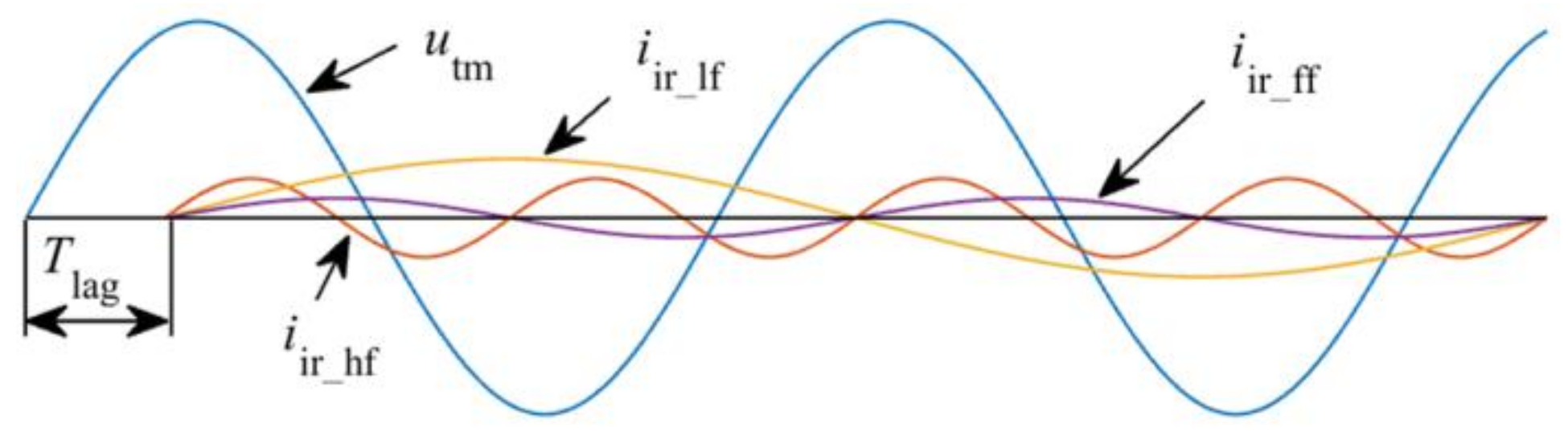
In this paper, for a DG unit, such as an inverter, in order to facilitate the implementation, an irregular current is injected in this pattern: the first zero phase of the irregular current iir lags a zero phase of the terminal voltage utm by Tlag (time), which is less than a period of both iir and utm, as shown in Figure 2. Tlag is expressed in terms of time rather than angle because the frequencies of the irregular current and terminal voltage may be different. Additionally, it is found that other injection patterns based on a terminal voltage reference can actually be attributed to this pattern.
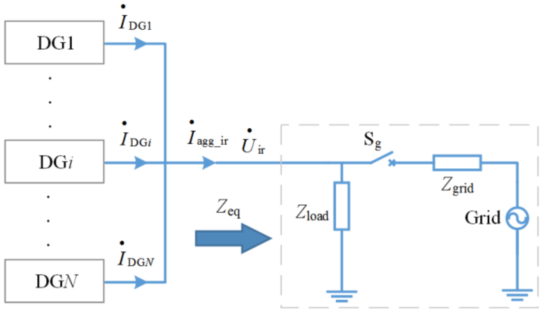
The following takes the DG1 and DG2 units in Figure 1 as an example to analyze how to achieve the mentioned phase difference requirement. If iDG1 and iDG2 are injected one after the other, the resultant waveforms are shown in Figure 3.
The relationship in (2) can be obtained from Figure 3:
TPu = nTPiir + kTPiir.
where TPu and TPiir are the periods of the terminal voltages and irregular currents, respectively; m is a positive integer; n is a non-negative integer; and there are:
n m 1   and   1 / 2 k 1 / 2 ,   for   high   frequency   currents m n 0 ,   m 1 ,   and   1 / 2 k 1 / 2 ,   for   low   frequency   currents   n = m 1   and   k = 0 ,   for   negative   sequence   fundamental   frequency   currents  
Mathematically, in Equation (2), n and kTPiir can be seen as the quotient and remainder of mTPu divided by TPiir, respectively. The relationship between m and n can be obtained from Figure 3 and the relationship between TPu and TPiir. For example, for high frequency currents, there is TPu > TPiir. If n < m, there will be n + k < m, and then Equation (2) cannot be established. Thus, there must be nm.
Equation (2) can be also rewritten as in (3), where fu and fiir are the frequencies of the terminal voltages and irregular currents, respectively, i.e., 1/TPu and 1/TPiir.
fiir/fu = (n + k)/m
To obtain compatibility, from Figure 3, k should be in the [−1/4, 1/4] interval, since it corresponds to Δφ12 (i.e., the phase difference mentioned in Section 2.2) in the [−π/2, π/2] interval. fu is certain and m represents the number of voltage cycles, which means m may be any positive integer. Thus, for a given fiir, if any value of m (i.e., any positive integer) can make k within [−1/4, 1/4] according to (3), this fiir is usable, otherwise it is unsuited to be used as an irregular current frequency. In other words, a usable fiir must be verified by all values of m, whereas an unusable fiir only needs to be verified by one value of m.

3.2. High-Frequency Current

Equation (4) can be obtained by substituting m = 1 into (3):
fiir/fu = n1 + k1
where n1 and k1 represent n and k when m = 1, respectively, as is the case hereafter; n1 is a positive integer due to fiir > fu; and −1/2 ≤ k1 ≤ 1/2 in accordance with (2).
According to the conclusion in Section 3.1, k1 should be in [−1/4, 1/4]. Thus, fiir which makes k1 outside this interval is unusable and is not considered below.
Then, by substituting m = 2 into (3), there is (5):
fiir/fu = (n2 + k2)/2
where n2 is an integer greater than 1 and −1/2 ≤ k2 ≤ 1/2.
The equation below can be derived from (4) and (5):
n2 + k2 = 2n1 + 2k1
So far, k1 has been constrained to be in [−1/4, 1/4], and thus, according to the above equation, Equation (6) is true considering that n1 and n2 are non-negative integers:
k2 = 2k
For m = 2, k2 should be also within [−1/4, 1/4]. Thereupon, the usable interval of k1 is compressed into [−1/8, 1/8] due to the above relationship, and the fiir corresponding to those k1 that have been filtered out will no longer be considered.
As above, when m = 3, the usable interval of k1 is further compressed into [−1/12, 1/12]. Hence, the usable intervals of k1 with the increase of m can be shown below.
m      Usable intervals of k1
1          [−1/4, 1/4]
2          [−1/8, 1/8]
⁞               ⁞
h        −1/(4h), 1/(4h)]
⁞              ⁞
When m→+∞, k1 can only be taken to zero, which means that k2 can only be zero due to (6), and the same is true for k3, k4, …. Consequently, considering—(4) and (5), there are the following equations:
f iir   / f u = n 1 ,   when   m = 1 f iir   / f u = n 2 / 2 ,   when   m = 2 f iir   / f u = n h / h ,   when   m = h
Since a usable fiir must be verified by all values of m, a usable fiir must satisfy all of the above equations. Through the intersection operation on the above equations, the final expression of the usable fiir can be derived, as shown in (7):
fiir = pfu
where p is an integer greater than 1.
The above expression shows that only the frequencies that are integer multiples of the terminal voltage frequency are usable for high frequency currents.

3.3. Low-Frequency Current

In the same way, when m = 1, (4) is still true, and for low frequency currents, there are n1 = 1 or 0, and −1/2 ≤ k1 ≤ 1/2 and k1 ≠ 0.
By following the derivation in Section 3.2, it can be found that there is not a suitable value for k1 considering k1 ≠ 0. In other words, low frequency currents are unsuited to be used as injected currents.

3.4. Negative Sequence Fundamental Frequency Currents

This type of current only exists in three-phase systems. Up to now, such currents have seemed to be usable, since (2) indicated that k = 0, i.e., within [−1/4, 1/4].

3.5. Practical Applications in Three-Phase Systems

In inverter-based three-phase DG systems, due to a lack of a relevant knowledge, carelessness or some other reasons, there may be a fault whereby the phase symbols of an inverter do not correspond to that of the system, while their phase sequence is the same. This fault is called a phase symbol fault in this paper, and it cannot be detected by a DG unit itself or even be seen as a fault. This scenario, as DG2 and DG3 units shown in Figure 4, is acceptable in terms of generation. Accordingly, irregular current injection islanding detection methods must also be able to tolerate this fault. As for the fault that a DG unit mismatches the phase sequence, as the DG4 unit shown in Figure 4, it will be detected by the DG unit. Depending on the technical route, the DG unit may adjust its inner phase sequence to adapt this fault, by which this fault is translated into a phase symbol fault, or the DG unit may refuse to start and issue a warning. Accordingly, this fault is seen as a phase symbol fault below.
(1) Positive Sequence High-Frequency Currents: We take the DG1 unit in Figure 4 as an example, where the reference terminal voltages of the irregular currents iira1, iirb1 and iirc1 are the line voltages (i.e., phase-to-phase voltage) uAB, uBC and uCA respectively, and Tlag is appointed as Ta, Tb and Tc, respectively.
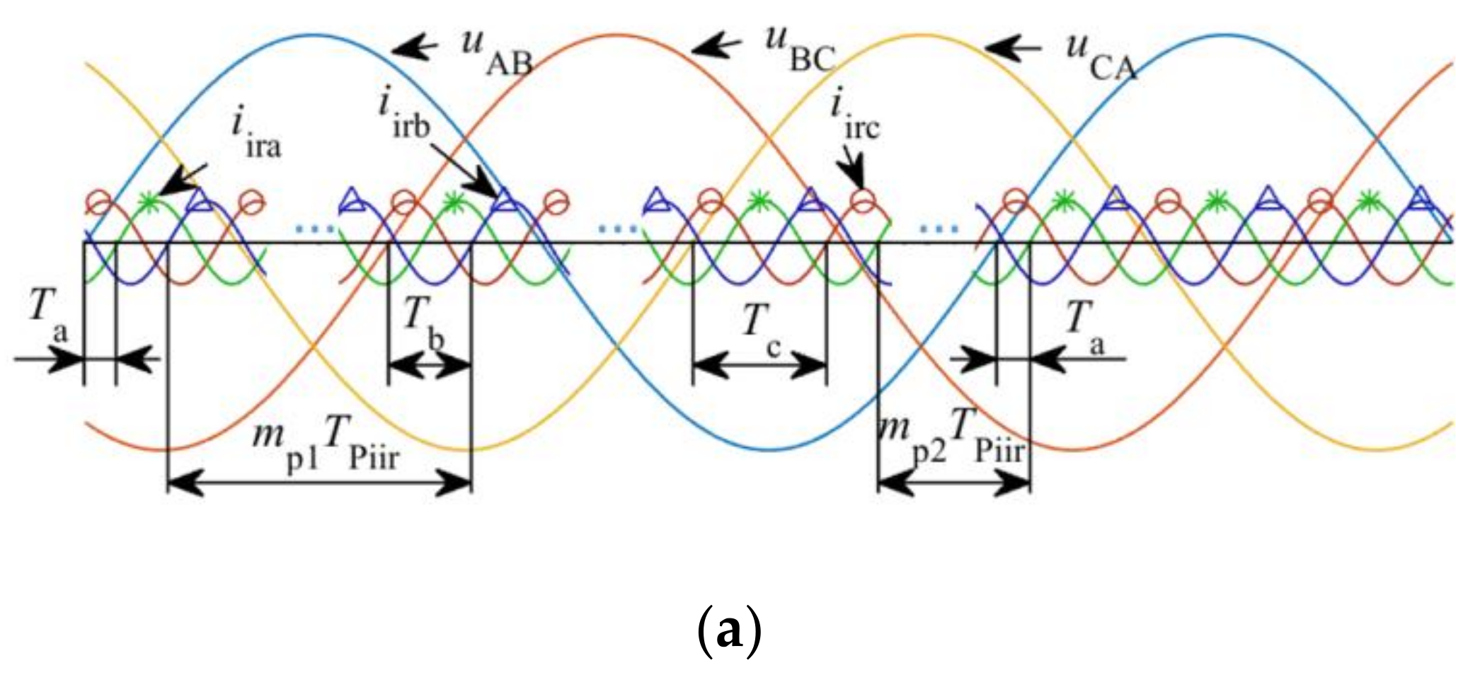
The time interval between the zero phase of a reference terminal voltage and the zero phase of an irregular current immediately following it is defined as the zero phase interval hereafter. The first zero phase interval must be Tlag for an irregular current in accordance with the aforementioned injection pattern, and once (7) is met, each subsequent zero phase interval will be Tlag. Thus, the positive sequence irregular current injection is shown in Figure 5a.
In Figure 5, the phase difference of 2π/3 between any two irregular currents corresponds to a time of TPiir/3, while the phase difference of 2π/3 between any two voltages corresponds to a time of TPu/3. Accordingly, Equations (8) can be obtained from Figure 5a:
T b = T a + T Piir / 3 + m p 1 T Piir T Pu / 3 T c = T a + T Pu / 3 T Piir / 3 m p 2 T Piir
where mp1 and mp2 are non-negative integers, and each non-negative integer may be the value of mp1 and mp2. For a certain irregular current (i.e., with a certain TPiir), Tb and Tc are determined by Ta. Consequently, only Ta needs to be set for three-phase DG units.
In Figure 4, the actual reference terminal voltage of both iirb1 and iira2 is uBC, while their Tlag are Tb and Ta, respectively. To make the phase difference between iirb1 and iira2 within [−π/2, π/2] for they converge in phase B, the time difference between the zero phases of iirb1 and iira2 should be in [−TPiir/4, TPiir/4]. Therefore, the inequality below should be satisfied, where Tint can be one value of 0, −TPiir and TPiir, and the three values correspond to the three scenarios shown in Figure 6:
TPiir/4 ≤ Tb + TintTaTPiir/4
Then, Equation (9) can be derived from the above inequality and (8), where q is a positive integer. For the other irregular currents in Figure 4, this equation can also be derived:
fiir/fu = 3q + 1
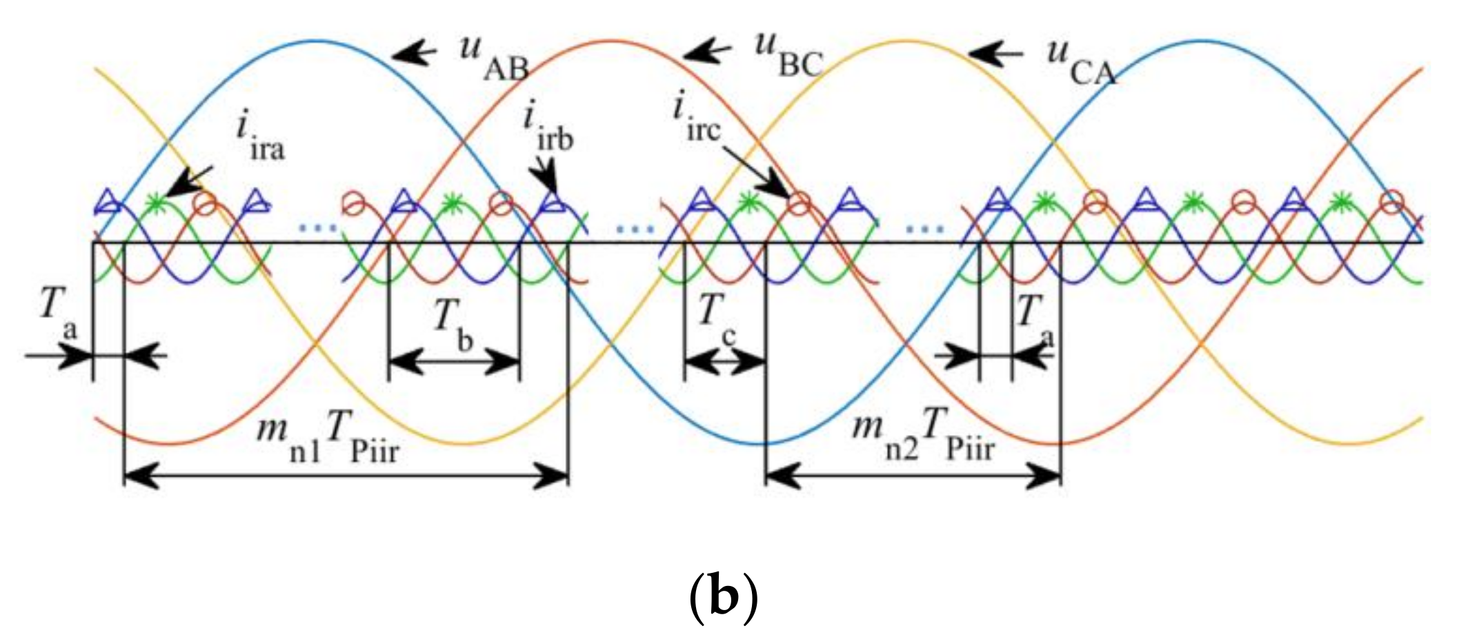
(2) Negative Sequence Fundamental/High-Frequency Currents: The injection of such currents is shown in Figure 5b. As in (8), there are similar equations, as shown in (10):
T b = T a + m n 1 T Piir T Pu / 3 T Piir / 3 T c = T a + T Pu / 3 + T Piir / 3 m n 2 T Piir
where mn1 and mn2 are non-negative integers, and each non-negative integer may be the value of mn1 and mn2.
By following the derivation for positive sequence high frequency currents above, Equation (11) can be obtained:
fiir/fu = 3q − 1
Equations (9) and (11) show further constraints on the frequencies of positive sequence current and negative sequence current, respectively. In addition, since the right side of (11) cannot be 1, the negative sequence fundamental frequency currents are unusable.

3.6. Practical Applications in Single-Phase Systems

For ease of use, the parameters of a single-phase DG unit, including the Tlag, do not need to be modified when the phase that it is connected to is changed. Thus, the single-phase DG units in Figure 7 must adopt the same Tlag, which is denoted as Tl in this paper. Since a single-phase DG unit can distinguish a live wire from a neutral wire, there is not a phase symbol fault as above.
Meanwhile, single-phase DG units should be compatible with three-phase DG units. Thus, in Figure 7, the phase difference between irregular currents iirs1 and iira must be in [−π/2, π/2] (i.e., the time difference between the zero phases of iirs1 and iira should be in [−TPiir/4, TPiir/4]), as for the other irregular currents. Since the reference terminal voltage of a single-phase DG unit is a phase voltage, e.g., uAN for iirs1, considering that uAN lags uAB by π/6 (time of TPu/12), as shown in Figure 8, Tl should be set as (12), where ma (as well as mb and mc, to be mentioned later) is an integer.
TPiir/4 ≤ (Tl + TPu/12) − TamaTPiirTPiir/4
Moreover, for phases B and C, the relationships below should be met:
TPiir/4 ≤ (Tl + TPu/12) − TbmbTPiirTPiir/4
TPiir/4 ≤ (Tl + TPu/12) − TcmcTPiirTPiir/4
As (12) is mandatory with the setting of Tl, the main thing is how to ensure that the above two inequalities are true. If iira, iirb and iirc in Figure 7 are positive sequence currents, by substituting (8) into the above two inequalities and considering (12), a relationship like (9) can be derived with regard to fiir. In addition, if iira, iirb and iirc are negative sequence currents, by substituting (10) into the above two inequalities and considering (12), a relationship like (11) can be derived. In other words, the frequencies determined by (9) and (11) (disregarding the phase sequence) are usable for single-phase DG units.
After the above analysis, it is found that the usable irregular currents are those with the frequencies determined by (7), i.e., integer multiple harmonics. The orders of 3q + 1 are assigned to positive sequence currents and single-phase currents, while the orders of 3q − 1 are assigned to negative sequence currents and single-phase currents, and the remainder are the orders of 3q. It seems that the orders of 3q can be used by single-phase currents, since they are used by neither positive sequence nor negative sequence currents and there is no compatibility issue between irregular currents at different frequencies. The following will study whether it is feasible.
As shown in Figure 7, it is assumed that the magnitudes of iirs1, iirs2 and iirs3 are the same. Their injections are shown in Figure 9, where iirs1 leads iirs2 by T12 (Time); iirs2 leads iirs3 by T23; and ms is a non-negative integer.
From Figure 9, there is the following relationship:
msTPiir + T12 = TPu/3
It can be rewritten as the following equation, where 0 ≤ T12/TPiir < 1:
T12/TPiir = fiir/(3fu) − ms
By substituting the preceding mentioned three sets of frequencies into the above equation, the results of T12/TPiir can be obtained below:
T 12 T Piir = 1 / 3 ,   if   f iir = ( 3 q + 1 ) f u 0 ,   if   f iir = 3 q f u 2 / 3 ,   if   f iir = ( 3 q 1 ) f u
For T23/TPiir, the same results as above can be obtained by following the preceding derivation. These results reflect that if the frequency of iirs1, iirs2 and iirs3 is (3q + 1)fu, iirs1 leads iirs2 by 2π/3 while iirs2 leads iirs3 by 2π/3, which means that iirs1, iirs2 and iirs3 are present as a set of positive sequence currents in the system; if their frequency is (3q − 1)fu, they will present as a set of negative sequence currents, and if their frequency is 3qfu, they will present as a set of zero sequence currents. However, zero sequence currents may bring some problems to the system. For example, they may affect zero-sequence relay protection [27]. When the single-phase DG units are evenly distributed on the three-phase lines, iirs1, iirs2 and iirs3 are likely to possess the same or similar magnitudes. Accordingly, for the frequencies of single-phase currents, the orders of 3q are not recommended.

3.7. Implementation of the Proposed Solution

For inverter-based DG units, since both fundamental currents and irregular currents are sinusoid, to simplify the control, PR regulation based on α-β reference frame is suggested. The control block diagrams are shown in Figure 10.
In Figure 10a, P and N denote the connection position of the multi-route switches when injecting positive sequence and negative sequence irregular currents, respectively, and A denotes the amplitude of the irregular current. To avoid the accumulation of phase errors resulting from the measurement errors of voltage frequency (i.e., ω), the irregular current phase θir should be reset periodically (shown as Syn. reset in Figure 10). For an irregular current whose frequency is an integer multiple of the voltage frequency, the irregular current phase should be reset once every voltage cycle. In addition, for the other irregular currents, for example, a current at 75 Hz, since two voltage (50 Hz) cycles include an integer number (three) cycles of this irregular current, the irregular current phase should be reset once every two voltage cycles. The counter in Figure 10 is used for counting voltage cycles.

4. Other Factors Relating to Irregular Current Injection

(1) Mixed with Existing Irregular Current Injection Methods: Since the irregular currents based on existing methods are not injected according to the proposed solution, they may offset the irregular currents injected according to the solution. Thus, the islanding detection effect will not be improved if there are few DG units employing the proposed solution. In terms of this problem, manufacturers are strongly encouraged to adopt the proposed solution.
(2) Tlag: A unified Tlag is critical for the compatibility. This paper has indicated that Ta and Tl should meet (12). However, no performance index has been found related to Tlag, and thus there is not a best value for Tlag. Accordingly, at present, a feasible way is to specify a value for it by the grid code makers. For example, Ta and Tl can be set as in Equation (13).
T a = T Pu / 12 T l = 0
(3) Resonant Frequency of the Filter of an Inverter: For the most common voltage source inverters, essentially, the irregular current is excited by an output voltage component with the same frequency. Therefore, for an inverter adopting a LC or LCL filter, its irregular current frequency should avoid the resonant frequency of the filter so as not to cause a current spike [28].
(4) Variation of the Grid Impedance: Some literature has pointed out that grid impedance is frequency-variant, and may be larger than the load impedance at a large enough frequency [4,20]. From this point of view, the irregular current frequency should be as small as possible, since a small grid impedance is a necessary condition for irregular current injection methods.
(5) Large Line Impedance: There may be a large line impedance between DG units that are far from each other, by which the terminal voltages of these DG units may be out of phase and thereby the irregular currents cannot be controlled as accurately as expected. At present, there is no good solution to this problem without communication.

5. Discussion on the Proposed Solution

A solution to the compatibility issue can be summarized as the following three points:
(1)
The terminal voltage of a DG unit is referenced, and the injection pattern of irregular currents is shown in Figure 2;
(2)
The usable frequency orders for irregular currents are shown in Table 1;
(3)
The used frequency should be as low as possible.
Furthermore, as a specific implementation of the proposed solution, the block diagram in Figure 10 can be employed by inverters.
In the meantime, it can be seen that along with the growing penetration of low and medium power DG units, particularly those of the plug and play variety, manufacturers, grid code makers and grid operators should cooperate to get both a satisfactory islanding detection effect.
This solution largely solves the compatibility issue, although not completely. In other words, if the phases of the irregular currents are still not managed as they are now, the effect of irregular current injection methods will be uncontrollable in multi-DG operation.

6. Simulations and Experiments

The proposed solution is implemented according to Figure 10 and Tlag is set as Equation (13).

6.1. Simulations

The three-phase inverter-based simulation platform is based on Matlab/Simulink (Matlab R2018a, Mathworks, Natick, MA, USA). The main circuits shown in Figure 11a and Figure 12a represent a normal connection and a phase symbol fault, respectively.

6.1.1. Tests under a Normal Connection

Positive sequence high frequency current (75 Hz) and positive sequence low frequency current (10 Hz) are tested. The simulation results are shown in Figure 11b,c, where the irregular current of each branch and their convergence are in phase A. The waveforms of iir_act are obtained by filtering (Band Pass) the output currents (i.e., i1, i2 and iagg) in Figure 11a. The results show that the reference irregular currents iir_ref are generated in the predetermined manner, and the actual irregular currents iir_act are well controlled in terms of tracing performance. In the meantime, the aggregate irregular current iagg_irA_act is distinctly smaller than both of the branch irregular currents i1_ira_act and i2_ira_act, which means that irregular currents at these two frequencies are unusable for islanding detection.

6.1.2. Tests under a Phase Symbol Fault

To simulate a phase symbol fault, the terminal phases a/b/c of inverter II are connected to the phases B/C/A of the power grid, respectively, as shown in Figure 12a. The test of negative sequence fundamental frequency current (50 Hz) is based on this circuit. The simulation results are shown in Figure 12b, where i1_ira_act and i2_irc_act converge on phase A and their Tlag are Ta and Tc, respectively. From the results, the reference irregular currents are still generated in the predetermined manner, and the actual irregular currents are also well controlled. Additionally, the aggregate current iagg_irA_act is smaller than i1_ira_act. In other words, the aggregate current is pulled down with the injection of i2_irc_act. Thus, this irregular current is unusable when considering phase symbol faults.
In summary, the control of the irregular currents has reached the expected effect. As for unusable frequencies, the simulation results are consistent with the previous conclusions.

6.2. Experiments

6.2.1. Tests under a Normal Connection

This set of tests are based on the circuit in Figure 11a. From Figure 10, the related parameters are shown in Table 2, where kP and kR are the proportional and resonant coefficients of the PR regulators for fundamental currents, respectively; kP_ir and kR_ir are the proportional and resonant coefficients of the PR regulators for irregular currents, respectively; AI and AII are the amplitude of the irregular currents output by inverters I and II, respectively; and fPWM is the switching frequency.
Moreover, in order to be more realistic, a hybrid of fundamental current and irregular current will be output by each inverter, and both the inverters are based on unity power factor control. Inverter I outputs a fundamental current of 5 A (amplitude) while inverter II outputs 3.5 A.
(1) Positive Sequence 75 Hz Current: Inverter I outputs an irregular current of 0.6 A (amplitude) while inverter II outputs 0.3 A. The experimental results are shown in Figure 13, where the irregular currents i1_ira, i2_ira, iagg_irA, i1_irb, i2_irb and iagg_irB are extracted from i1_a, i2_a, iagg_A, i1_b, i2_b and iagg_B, respectively. This extraction is realized through offline filtering of the currents at other frequencies (by band pass filters) and the opposite phase sequence current at the same frequency (by delayed signal cancellation algorithm) [29]. Although the filtered data will have a phase deviation, they are generally applicable for analysis.
In the right side of Figure 13, the horizontal bold solid lines represent the zero phase interval, mentioned in Section 3.5, regarding i1_ira. The zero phase interval near point P1 (a zero phase of uab) is approximately TPu/12, and the one near point P2 (another zero phase of uab) is approximately 5TPu/12. It reveals that the zero phase intervals are different for this irregular current. Thereupon, if another irregular current starts to be injected after point P1, it will be in phase with i1_ira considering that Ta is set to TPu/12, whereas if it starts to be injected after point P2, the phase difference between i1_ira and it will not be within [−π/2, π/2]. This analysis reveals that the phase difference between such two currents injected at different times may be within or outside [−π/2, π/2], and actually, both cases have occurred during the tests, although only the case whose phase difference is outside [−π/2, π/2] is illustrated with Figure 13 (i1_ira and i2_ira). This phase difference is uncontrollable in applications, which is enough to indicate that this irregular current is unusable.
(2) Negative Sequence 10 Hz Current: The amplitudes of the irregular currents are the same as above. The experimental results are shown in Figure 14.
In Figure 14, there are five cycles of uab in a cycle of i1_ira. In other words, there are five zero phase points of uab in a cycle of i1_ira. If another irregular current starts to be injected after one of the five zero phase points, the phase difference between i1_ira and it is likely to be outside [−π/2, π/2], as is the case shown in Figure 14 (i1_ira and i2_ira). This phase difference is still uncontrollable, which means that this irregular current is also unusable.
(3) Positive Sequence 200 Hz Current: Inverter I outputs such an irregular current of 0.8 A (amplitude) while inverter II outputs 0.5 A. The experimental results are shown in Figure 15.
In Figure 15, as mentioned in Section 3.5, every zero phase interval is the same for i1_ira and i2_ira, and is equal to Ta, i.e., TPu/12. Accordingly, i1_ira and i2_ira are in phase, as shown in Figure 15, and thereby this irregular current is usable.
(4) Negative Sequence 50 Hz Current: The amplitudes of the irregular currents are the same as above. The experimental results are shown in Figure 16.
In Figure 16, every zero phase interval is still the same. Thus, i1_ira and i2_ira are still in phase, and this irregular current is usable here.

6.2.2. Tests under a Phase Symbol Fault

This set of tests are based on the circuit in Figure 17. The related parameters and output of fundamental currents are the same as those in Section 6.2.1.
(1) Positive Sequence 200 Hz Current: Inverter I outputs an irregular current of 0.8 A (amplitude) while inverter II outputs 0.5 A. The experimental results are shown in Figure 18.
In Figure 17, i1_irc and i2_ira converge on phase A. According to the analyses in the previous subsection, the zero phase interval of i1_irc is always Tc while that of i2_ira is always Ta. At this point, there is exactly Ta = Tc. Accordingly, i1_irc and i2_ira are still in phase, as shown in Figure 18. Therefore, this irregular current is usable.
(2) Negative Sequence 50 Hz Current: The amplitudes of the irregular currents are the same as above. The experimental results are shown in Figure 19.
The zero phase intervals of i1_irc and i2_ira are still Tc and Ta, respectively. However, Tc is no longer equal to Ta. In Figure 19, i1_irc approximately leads i2_ira by 2π/3, i.e., outside [−π/2, π/2]. Consequently, this irregular current is unusable, although it performs well under normal connection.
Overall, of the several irregular currents tested, only the positive sequence 200 Hz current is usable, which is consistent with Table 1.

7. Conclusions

For irregular current injection islanding detection methods in multi-DG operation, if the phases of the injected irregular currents at the same frequency are not managed, the aggregate irregular current may be smaller than the individual injected irregular currents, which may result in a failed islanding detection. Accordingly, a compatibility issue is raised, which requires the phase difference between any two injected irregular currents within a certain interval. From this requirement, a solution is proposed, which references the terminal voltage of DG units to conduct irregular current injection and only employs the high frequency currents whose frequencies satisfy a certain constraint, as shown in Table 1. This solution can largely eliminate the phenomenon that irregular currents cancel each other out, and ensures that every injected irregular current can have a positive effect for islanding detection. Therefore, it is meaningful for practical applications. If this solution is employed, a good foundation will be laid for the next stage of islanding detection. Accordingly, a better effect and reliability can be expected.

Author Contributions

All authors contributed their advice to the implementation of simulation and experiment. M.L. and W.Z. conceived the methodology; M.L. programmed the digital signal processor and implemented the validation; Q.W. did a writing-review & editing and gave advice on the structure of this paper.

Funding

This research received no external funding.

Acknowledgments

This paper is an extended study based on one of our papers presented at 3rd IEEE International Conference on Green Energy and Applications.

Conflicts of Interest

The authors declare no conflict of interest.

References

  1. Voglitsis, D.; Papanikolaou, N.; Kyritsis, A.C. Incorporation of harmonic injection in an interleaved flyback inverter for the implementation of an active anti-islanding technique. IEEE Trans. Power Electron. 2017, 32, 8526–8543. [Google Scholar] [CrossRef]
  2. Emadi, A.; Afrakhte, H.; Sadeh, J. Fast active islanding detection method based on second harmonic drifting for inverter-based distributed generation. IET Gener. Transm. Distrib. 2016, 10, 3470–3480. [Google Scholar] [CrossRef]
  3. Cai, W.; Liu, B.; Duan, S.; Zou, C. An islanding detection method based on dual-frequency harmonic current injection under grid impedance unbalanced condition. IEEE Trans. Ind. Inform. 2013, 9, 1178–1187. [Google Scholar] [CrossRef]
  4. Tedde, M.; Smedley, K. Anti-islanding for three-phase one-cycle control grid tied inverter. IEEE Trans. Power Electron. 2014, 29, 3330–3345. [Google Scholar] [CrossRef]
  5. Hou, C.-C.; Chen, Y.-C. Active anti-islanding detection based on pulse current injection for distributed generation systems. IET Power Electron. 2013, 6, 1658–1667. [Google Scholar] [CrossRef]
  6. Karimi, H.; Yazdani, A.; Iravani, R. Negative-sequence current injection for fast islanding detection of a distributed resource unit. IEEE Trans. Power Electron. 2008, 23, 298–307. [Google Scholar] [CrossRef]
  7. Wu, Z.; Yang, F.; Luo, Z.; Hang, Q.L. A novel active islanding fault detection based on even harmonics injection and set-membership filtering. In Proceedings of the Intelligent Control and Automation, Shenyang, China, 29 June–4 July 2015; pp. 3683–3689. [Google Scholar]
  8. Timbus, A.V.; Teodorescu, R.; Blaabjerg, F.; Borup, U. Ens detection algorithm and its implementation for pv inverters. IEE Proc. Electr. Power Appl. 2006, 153. [Google Scholar] [CrossRef]
  9. Kim, H.J.; Kim, D.H.; Han, B.M. Islanding detection method with negative-sequence current injection under unbalanced grid voltage. In Proceedings of the Future Energy Electronics Conference, Taipei, Taiwan, 1–4 November 2015. [Google Scholar]
  10. Asiminoaei, L.; Teodorescu, R.; Blaabjerg, F.; Borup, U. A digital controlled pv-inverter with grid impedance estimation for ens detection. IEEE Trans. Power Electron. 2005, 20, 1480–1490. [Google Scholar] [CrossRef]
  11. Vijayakumari, A.; Devarajan, A.T.; Devarajan, N.; Vijith, K. Dynamic grid impedance calculation in d-q frame for micro-grids. In Proceedings of the Power and Energy Systems Conference: Towards Sustainable Energy, Bangalore, India, 13–15 March 2014. [Google Scholar]
  12. Dai, Z.; Chong, Z.; Liu, X.; Li, C. Active islanding detection method based on grid-connected photovoltaic inverter and negative sequence current injection. In Proceedings of the International Conference on Power System Technology, Chengdu, China, 20–22 October 2014; pp. 1685–1690. [Google Scholar]
  13. Briz, F.; Diaz-Reigosa, D.; Blanco, C.; Guerrero, J.M. Coordinated operation of parallel-connected inverters for active islanding detection using high-frequency signal injection. IEEE Trans. Ind. Appl. 2014, 50, 3476–3484. [Google Scholar] [CrossRef]
  14. Reigosa, D.D.; Briz, F.; Charro, C.B.; Guerrero, J.M. Islanding detection in three-phase and single-phase systems using pulsating high-frequency signal injection. IEEE Trans. Power Electron. 2015, 30, 6672–6683. [Google Scholar] [CrossRef]
  15. Kim, B.H.; Sul, S.K.; Lim, C.H. Anti-islanding detection method using negative sequence voltage. In Proceedings of the Power Electronics and Motion Control Conference, Harbin, China, 2–5 June 2012; pp. 604–608. [Google Scholar]
  16. García, P.; Guerrero, J.M.; García, J.; Navarro-Rodríguez, Á.; Sumner, M. Low frequency signal injection for grid impedance estimation in three phase systems. In Proceedings of the Energy Conversion Congress and Exposition, Pittsburgh, PA, USA, 14–18 September 2014; pp. 1542–1549. [Google Scholar]
  17. Hu, S.H.; Tsai, H.T.; Lee, T.L. Islanding detection method based on second-order harmonic injection for voltage-controlled inverter. In Proceedings of the Future Energy Electronics Conference, Taipei, Taiwan, 1–4 November 2015. [Google Scholar]
  18. Liu, M.; Zhao, W.; Wang, Q.; Huang, S.; Shi, K. An irregular current injection islanding detection method based on an improved impedance measurement scheme. Energies 2018, 11, 2474. [Google Scholar] [CrossRef]
  19. Khodaparastan, M.; Vahedi, H.; Khazaeli, F.; Oraee, H. A novel hybrid islanding detection method for inverter-based dgs using sfs and rocof. IEEE Trans. Power Deliv. 2017, 32, 2162–2170. [Google Scholar] [CrossRef]
  20. Liu, N.; Aljankawey, A.; Diduch, C.; Chang, L.; Su, J. Passive islanding detection approach based on tracking the frequency-dependent impedance change. IEEE Trans. Power Deliv. 2015, 30, 2570–2580. [Google Scholar] [CrossRef]
  21. Liu, X.; Kennedy, J.M.; Laverty, D.M.; Morrow, D.J.; McLoone, S. Wide-area phase-angle measurements for islanding detection—An adaptive nonlinear approach. IEEE Trans. Power Deliv. 2016, 31, 1901–1911. [Google Scholar] [CrossRef]
  22. Kreishan, M.; Fotis, G.; Vita, V.; Ekonomou, L. Distributed generation islanding effect on distribution networks and end user loads using the load sharing islanding method. Energies 2016, 9, 956. [Google Scholar] [CrossRef]
  23. Ekonomou, L.; Fotis, G.P.; Vita, V.; Mladenov, V. Distributed generation islanding effect on distribution networks and end user loads using the master-slave islanding method. J. Power Energy Eng. 2016, 4, 1–24. [Google Scholar] [CrossRef]
  24. Liu, M.; Zhao, W.; Huang, S.; Wang, Q.; Shi, K. Problems in the classic frequency shift islanding detection methods applied to energy storage converters and a coping strategy. IEEE Trans. Energy Convers. 2018, 33, 496–505. [Google Scholar] [CrossRef]
  25. Voglitsis, D.; Valsamas, F.; Rigogiannis, N.; Papanikolaou, N. On the injection of sub/inter-harmonic current components for active anti-islanding purposes. Energies 2018, 11, 2183. [Google Scholar] [CrossRef]
  26. Liu, M.; Zhao, W.; Huang, S.; Wang, Q.; Shi, K. Synchronization Issues with Irregular Current Injection Islanding Detection Methods in Multi-DG Operation. In Proceedings of the 3rd IEEE International Conference on Green Energy and Applications, Taiyuan, China, 16–18 March 2019. [Google Scholar]
  27. Guo, X.; Han, B.; Lei, J.; Wang, G. A novel adaptive zero-sequence current protection for low resistance grounding system. In Proceedings of the Power and Energy Engineering Conference, Xi’an, China, 25–28 October 2016; pp. 2523–2528. [Google Scholar]
  28. Reigosa, D.; Briz, F.; Charro, C.B.; Garcia, P.; Guerrero, J.M. Active islanding detection using high-frequency signal injection. IEEE Trans. Ind. Appl. 2012, 48, 1588–1597. [Google Scholar] [CrossRef]
  29. Alfonso-Gil, J.C.; Vague-Cardona, J.J.; Orts-Grau, S.; Gimeno-Sales, F.J.; Segui-Chilet, S. Enhanced grid fundamental positive-sequence digital synchronization structure. IEEE Trans. Power Deliv. 2013, 28, 226–234. [Google Scholar] [CrossRef]
Figure 1. Irregular currents and voltage in multi-DG operation.
Energies 12 01467 g001
Figure 2. Injection pattern of irregular currents. utm: terminal voltage; iir_hf: high frequency current; iir_lf: low frequency current; iir_ff: negative sequence fundamental frequency current.
Energies 12 01467 g002
Figure 3. Scenarios that two irregular currents are injected. (a) High-frequency currents; (b) Low-frequency currents; (c) Negative sequence fundamental frequency currents.
Energies 12 01467 g003aEnergies 12 01467 g003b
Figure 4. Multiple three-phase DGs.
Energies 12 01467 g004
Figure 5. Injection of three-phase irregular currents. (a) Positive sequence irregular current; (b) Negative sequence irregular current.
Energies 12 01467 g005aEnergies 12 01467 g005b
Figure 6. Possible relationship between Ta and Tb to achieve the mentioned phase difference. (a) Tint = 0; (b) Tint = −TPiir; (c) Tint = TPiir. The bold lines represent the proper position for the first zero phase of iirb1 to make the phase difference between iirb1 and iira2 within [−π/2, π/2].
Energies 12 01467 g006
Figure 7. Hybrid of single-phase and three-phase DG.
Energies 12 01467 g007
Figure 8. Relationship between Ta and Tl.
Energies 12 01467 g008
Figure 9. Phase relationship between the single-phase irregular currents.
Energies 12 01467 g009
Figure 10. Implementation of the proposed solution. (a) For three-phase inverters; (b) For single-phase inverters.
Energies 12 01467 g010
Figure 11. Waveforms under normal connection. (a) Main circuit; (b) Positive sequence high-frequency current (75 Hz); (c) Positive sequence low-frequency current (10 Hz). uAB: reference terminal voltage (50 Hz). The meaning of the subscripts: ref, reference current; act, actual current; ira, irregular current of phase a; agg, aggregate current.
Energies 12 01467 g011aEnergies 12 01467 g011b
Figure 12. Waveforms under a phase symbol fault. (a) Main circuit with a phase symbol fault; (b) Negative sequence fundamental frequency current (50 Hz).
Energies 12 01467 g012
Figure 13. Actual positive sequence 75 Hz currents. Current i1_a is output by the phase A of inverter I while i1_ira is the irregular current therein, and the others can be analogized.
Energies 12 01467 g013
Figure 14. Actual negative sequence 10 Hz current.
Energies 12 01467 g014
Figure 15. Actual positive sequence 200 Hz current.
Energies 12 01467 g015
Figure 16. Actual negative sequence 50 Hz current.
Energies 12 01467 g016
Figure 17. Main circuit in which inverter I has a phase symbol fault.
Energies 12 01467 g017
Figure 18. Actual positive sequence 200 Hz current.
Energies 12 01467 g018
Figure 19. Actual negative sequence 50 Hz current.
Energies 12 01467 g019
Table 1. Usable frequency orders for irregular currents.
Irregular CurrentsUsable Orders 1
Three-phase positive sequence currents3q + 1
Three-phase negative sequence currents3q − 1
Single-phase currents3q ± 1
1q is a positive integer.
Table 2. Related parameters of the inverters.
kPkRkP_irkR_irAI (A)AII (A)fPWM (kHz)
17.732895.0610120.6/0.80.3/0.510

