Article

Observer-Based Sliding Mode Control to Improve Stability of Three-Phase LCL-Filtered Grid-Connected VSIs

1
Department of Electrical Engineering, Shanghai Maritime University, Shanghai 201306, China
2
Department of Energy Technology, Aalborg University, 9220 Aalborg, Denmark
*
Author to whom correspondence should be addressed.
Energies 2019, 12(8), 1421; https://doi.org/10.3390/en12081421
Submission received: 2 March 2019 / Revised: 28 March 2019 / Accepted: 4 April 2019 / Published: 12 April 2019
(This article belongs to the Special Issue Control in Power Electronics)

Abstract

:
Grid-connected voltage source inverters (VSIs) with LCL filters have been widely used for distributed generation systems (DGs). Various control methods have been studied to achieve good performance. Among them, sliding mode control has been applied to LCL-filtered grid-connected VSIs for its fast, dynamic response and strong robustness. However, LCL networks can easily cause instability problems under weak grid conditions such as grid impedance variation. At the same time, the stability design of sliding mode control applied for LCL-filtered grid-connected inverters are important, but they lack detailed parameters design in recent papers. In this paper, a design of observer-based sliding mode control to improve the stability of three-phase LCL-filtered grid-connected VSIs was proposed. The theoretical stability analysis was developed to consider the effect of the system discretization and grid impedance variations. Finally, a 3-kW, 110-V, 50-Hz experimental setup has been built to demonstrate the validation of the proposed method.

1. Introduction

Due to energy demand and environmental problems, a grid-connected voltage source inverter (VSI) has been widely used in new energy power generation, especially in distributed generation systems (DGs) [1,2,3]. In order to inject high quality current into the power grid, a filter is needed to connect the inverter and the power grid to attenuate the high frequency harmonics caused by pulse width modulation (PWM) [4,5].
Among these various filters, the third-order LCL filter is a good choice in which to attain better attenuation ability with lower inductance compared with L and LC filters. However, an LCL filter has an inherent resonance problem, which causes system instability and brings complexity to the current regulator [6,7]. In general, in order to suppress the resonance, active and passive damping methods are frequently adopted to an LCL-filtered converter [8,9,10,11]. A passive damping method is usually realized by adding physical resistors to the filter, which will certainly result in power loss. An active damping method is usually adopted to construct a virtual resistor by using state feedback variables, in which one or more additional sensors are needed in the implementation. In addition, several control methods are also proposed without damping methods, which strongly depends on the LCL filter design and the sampling frequency [9]. However, grid-connected inverters are connected at the point-of-common-coupling (PCC) and the equivalent impedance of the power grid would change in a wide range, so that the resonance frequency of the system would probably vary, which can easily lead to instability in the digital implementation in DGs. Hence, the controller design becomes very important when facing increasingly complex and rough operation conditions [11].
Conventionally, current loop with a proportional integral (PI) controller is used for grid-connected converters. However, the poor reference tracking and stability issues are the main drawbacks for this type of controller. Instead of a PI controller, the proportional resonant (PR) controller has been widely used for good reference tracking and harmonic compensation under the grid disturbance [12,13]. In recent years, compared with these traditional linear control methods, various non-linear control methods, such as passivity-based control, sliding mode control (SMC), repetitive control, predictive control and deadbeat control, have been rapidly applied to LCL-filtered grid-connected VSIs [14,15,16,17,18,19,20,21,22,23,24,25,26]. Non-linear controllers show better control effects, such as strong robustness and fast dynamic response. Among these non-linear control methods, SMC has been widely studied in grid-connected converters due to its fast, dynamic response, strong robustness and good regulation properties [20,21,22,23,24,25,26].
Normally, for LCL-filtered grid-connected VSIs the sliding surface is formed based on the linear combination of various variables such as the inverter current error, the capacitor voltage error, the grid current error and derivatives of these variables. Different sliding mode functions could lead to different control effects in a number of required sensors. The SMC method introduced in [20] requires three sensors for measuring the grid and inverter and capacitor currents. To reduce the number of sensors for LCL-filtered inverters, the sliding mode controller was combined to the Kalman filter to estimate the actual variables needed in the sliding surface function formation [22,23]. As for the Kalman filter, the main merit is the good performance of the noise immunity, but it has an issue of high computational burden. As to the steady state error problem of the grid current, PR with multiple resonant terms controller has been used in the SMC [20,21]. The authors of Reference [25] introduced a virtual resistor in the converter model with sliding mode control to achieve a high robustness against internal and external disturbance. However, there are few papers which have provided a detailed design procedure of the sliding mode controller parameters of the LCL-filtered grid-connected inverter.
In this paper, an observer-based sliding mode control method is proposed to improve the stability of the three-phase LCL-filtered grid-connected VSI. In order to further reduce the cost and to facilitate design, a discrete state observer was constructed by only sampling two state variables, the grid-side current and the PCC voltage. Compared with the Kalman filter, as a similar senseless method to estimate the state vectors, a state observer is much simpler to implement and has been successfully applied to LCL-filtered grid-connected [27,28,29,30]. Because of the separation principle of a state observer, the design of the sliding mode controller and discrete state observer were separated. As to the current control loop, the sliding mode controller was built to regulate the inverter-side current, so the sliding surface is only based on the error of the inverter-side current in which the control law is much simpler and easy to implement. However, due to the resonance problem of an LCL filter, the stability range of the system will become smaller and the bandwidth cannot be improved. Thus, a modified sliding mode control law with active damping ability is proposed to improve the stability of the system and to reduce the sensitivity to grid inductance variations. Furthermore, the detailed parameters design of the proposed method has been described in consideration of the discretization time delay.
This paper is organized as following: Section 2 introduces the modeling of a three-phase grid-connected VSI with an LCL filter in αβ reference frame; Section 3 analyzes the proposed control approach and the design procedures; then, Section 4 presents experimental results of the whole system to verify the effectiveness and the theoretical considerations of the proposed method. Finally, some conclusions are derived in Section 5.

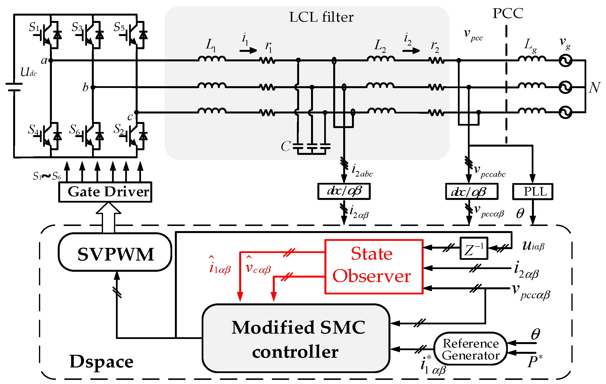
2. Modeling of a Three-Phase Grid-Connected VSI with an LCL Filter in αβ-Frame

Figure 1 shows the topology of a three-phase grid-connected VSI with an LCL filter and the basic control scheme of the proposed strategy. The LCL filter consists of an inverter-side inductor L1, a filter capacitor C, and a grid-side inductor L2. r1 and r2 are the parasitic resistances of inductors L1 and L2. Considering that most of the inverters are connected to the grid in parallel through the PCC in the DGs, here the impedance of the grid between the voltage vpcc at the PCC and the grid voltage vg is equivalent to a pure inductor Lg. The phase-locked loop (PLL) is used to generate the current reference i 1 synchronized with the PCC voltage. It can be seen from the Figure 1 that only two state vectors, the grid-side current i2 and the PCC voltage vpcc, are sensed in this system. The inverter-side current i ^ 1 and the capacitor voltage v ^ c obtained by state observer are used for SMC controller and realized in the stationary αβ-frame. uiαβ is the control signal synthesized by the SMC controller under the stationary αβ-frame. The values of the system parameters chosen for the theoretical analysis and experiments are given in Table 1.
The operation of the three-phase system can be described by the following equations:
L 1 d i 1 d t = u i i 1 r 1 v c
C d v c d t = i 1 i 2
L 2 d i 2 d t = v c i 2 r 2 v p c c
where the state vectors used for sliding mode control are defined as: the inverter-side currents: i 1 = [ i 1 a i 1 b i 1 c ] T , the capacitor voltages v c = [ v c a v c b v c c ] T , the grid-side currents i 2 = [ i 2 a i 2 b i 2 c ] T and the control signals vector u i = [ u i a u i b u i c ] T .
In order to facilitate the design of control and avoid the coupling problem in dq-frame, the operation of the system is converted to αβ-frame, shown in Equations (4)–(6):
{ L 1 d i 1 α d t = u i α i 1 α r 1 v c α L 1 d i 1 β d t = u i β i 1 β r 1 v c β
{ C d v c α d t = i 1 α i 2 α C d v c β d t = i 1 β i 2 β
{ L 2 d i 2 α d t = v c α i 2 α r 2 v p c c α L 2 d i 2 β d t = v c β i 2 β r 2 v p c c β
Then the state-space model of the system can be described by Equations (7) and (8):
x ˙ = A x + B u + D
A = [ r 1 L 1 0 1 L 1 0 0 0 0 r 1 L 1 0 1 L 1 0 0 1 C 0 0 0 1 C 0 0 1 C 0 0 0 1 C 0 0 1 L 2 0 r 2 L 2 0 0 0 0 1 L 2 0 r 2 L 2 ] , B = [ 1 L 1 0 0 1 L 1 0 0 0 0 0 0 0 0 ] , D = [ 0 0 0 0 v p c c α L 2 v p c c β L 2 ]
where: x = [ i 1 α i 1 β v c α v c β i 2 α i 2 β ] T , u = [ u i α u i β ] T .

3. Proposed Observer-Based Sliding Mode Control System

Figure 1 shows the control scheme of the whole system. Compared to a traditional sliding mode control method, the proposed control algorithm is based on a state observer and active damping method to improve the robustness against the grid inductance and system parameters variations. The grid-side current vector i 2 = [ i 2 a i 2 b i 2 c ] T is sensed for the input of the state observer. The PCC voltage vector v p c c = [ v p c c a v p c c b v p c c c ] T is sensed for PLL and the input of the state observer. Then the observed inverter-side current vector i 1 ^ = [ i ^ 1 α i ^ 1 β ] T , the observed capacitor voltage vector v ^ c = [ v ^ c α v ^ c β ] T and the reference inverter current vector i 1 = [ i 1 α i 1 β ] T are used in the modified SMC controller. Here are the detailed design procedures and stability analysis.

3.1. Basic SMC Controller

This section introduces the design of the basic SMC controller. Figure 2 shows the control scheme in the stationary αβ-frame. L 1 and r 1 are the measured values of the inverter-side inductor and the parasitic resistance, respectively. As a special non-linear control, the sliding mode control is based on Lyapunov stability analysis. The sliding surface was constructed by its desired goal, and then the control law was obtained by the Lyapunov stability analysis method, which forces the system to run to the desired trajectory. In this LCL-filtered grid-connected inverter system, the aim of the controller is to inject high-quality current into the grid in which the six state variables x = [ i 1 α i 1 β v c α v c β i 2 α i 2 β ] T are depicted in Equation (7) are the same as the desired reference state variables. Note that there is a delay problem in the process of digital implementation, which will greatly affect the stability of the system and needs to be considered.
(1) Select the sliding surface.
As a first step, the sliding surface vectors are defined to control the inverter currents, as shown in Equations (9) and (10):
s = [ s α s β ] T
{ s α = i 1 α i 1 α s β = i 1 β i 1 β { d s α d t = d i 1 α d t i 1 α d t d s β d t = d i 1 β d t i 1 β d t
(2) Choose the reaching law.
The reaching law method is an effective method to suppress the chattering of the system, which determines the dynamic characteristics of the system. Here, the exponential reaching law based on saturation function is selected by Equations (11) and (12):
{ d s α d t = k p s α ε s a t ( s α ) d s β d t = k p s β ε s a t ( s β )
s a t ( s ) = { 1 s > Δ k s a t s | s | Δ 1 s < Δ k s a t = 1 Δ
Note that this reaching law can increase the gain of kp and decrease the gain of non-linear links ε. The parameter selecting of ε and ksat is based on engineering experience. The ε is very small, and the sat function can be neglected without affecting the results.
(3) Get the control law.
Substituting Equation (7) into Equation (11) yields:
{ u i α = L 1 k p s α + L 1 ε s a t ( s α ) + L 1 d i 1 α d t + r 1 i 1 α v c α u i β = L 1 k p s β + L 1 ε s a t ( s β ) + L 1 d i 1 β d t + r 1 i 1 β v c β
In order to eliminate the inverter current tracking error and suppress the harmonics distortion, the proportional gain of the reaching law is replaced with the PR controller. The transfer function of PR controller is given by Equation (14):
G c ( s ) = k p + 2 k r ω i s s 2 + 2 ω i s + ω o 2
where kp is the proportional gain, and kr is the resonant gains, ωi and ωo is the cutoff angular frequency and the fundamental angular frequency. It should be noted that only the proportional gain of Gc(s), kp, is considered in the later analysis, since the resonant parts of Equation (14) are designed to improve steady-state tracking [24]. It has little effect in resonance damping, if the same proportional gain is used.
When considering the delay of digital implementation, it needs to be reflected in the control structure diagram. Ts is the sampling period. Gzoh(s) is the zero-order hold given by Equation (15):
G z o h ( s ) = 1 e T s s s
Thus, total delay Gd(s) is shown in Equation (16):
G d ( s ) = 1 T s e T s s G z o h ( s ) e 1.5 T s s
As shown in Figure 2, the control structure of the system can be obtained from the above analysis. Since the designed ε is very small compared to the main loop gain, the nonlinear link is negligible in the stability analysis. The closed-loop transfer function of the whole system considering the delay is given by Equation (17):
G c l o s e ( s ) = I 1 ( s ) I 1 ( s ) = a 3 s 3 + a 2 s 2 + a 1 s + a 0 b 3 s 3 + b 2 s 2 + b 1 s + b 0
where:
a 3 = C L 2 L 1 a 2 = C L 2 k p + C L 2 r 1 + C L 1 r 2 a 1 = L 1 + C k p r 2 + C r 2 r 1 a 0 = k p + r 1 b 3 = C L 1 L 2 e 1.5 T s s b 2 = C L 2 k p + C L 1 r 2 e 1.5 T s s + C L 2 r 1 e 1.5 T s s b 1 = L 2 + L 1 e 1.5 T s s + L 2 e 1.5 T s s + C k p r 2 + C r 1 r 2 e 1.5 T s s b 0 = k p + r 2 + r 1 e 1.5 T s s + r 2 e 1.5 T s s
The discrete closed-loop poles location of the whole system can be obtained from the closed -loop transfer function when 0.01 < kp < 5, as shown in Figure 3. The VSI is controlled using the conventional SMC without any damping strategy. It can be seen that the poles move out of the z-domain unit circle with increasing kp and the critical stable point is kp = 2. However, it should be noted that the resonant frequency largely depends on the grid impedance variations. In order to increase the system control bandwidth and robustness against the system parameters variations, the modified SMC and stability analysis will be proposed in the next sections.

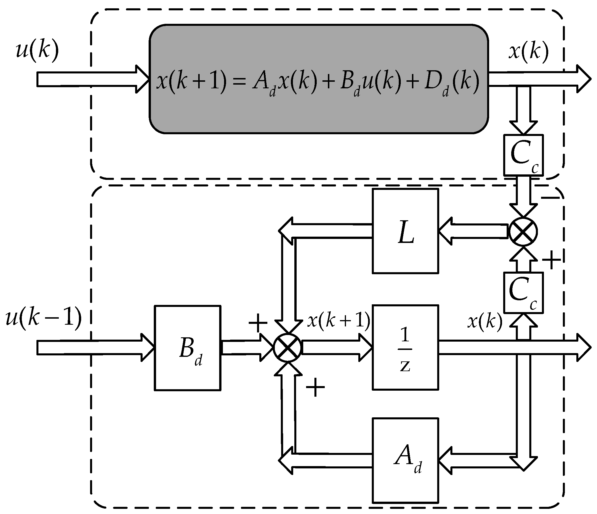
3.2. Discrete State Observer

This section introduces the design of a discrete state observer. It can see from the above control law that the system needs to detect three state variables in which nine sensors are needed. The state observer is an effective method to reduce system sensors, and it does not take up excessive computation in software computing. The inverter-side current i1 and capacitor voltage vc can be estimated with grid-side current i2 and the PCC voltage vpcc using a state observer.
For digital implementation, in the design of state observer, the system model shown in Equation (7) should be transformed into discrete state-space model, given in Equation (19):
{ x ( k + 1 ) = A d x ( k ) + B d u ( k ) + D d ( k ) y ( k ) = C c x ( k )
where:
A d = e A T s = [ 1 r 1 T s L 1 0 T s L 1 0 0 0 0 1 r 1 T s L 1 0 T s L 1 0 0 T s C 0 0 0 T s C 0 0 T s C 0 0 0 T s C 0 0 T s L 2 0 1 r 2 T s L 2 0 0 0 0 T s L 2 0 1 r 2 T s L 2 ] ,   B d = 0 T S e A τ d τ B = [ T s L 1 0 0 T s L 1 0 0 0 0 0 0 0 0 ] ,   D d = 0 T S e A τ d τ D = [ 0 0 0 0 v p c c α L 2 v p c c β L 2 ]
Using the mode in Equation (19), a closed-loop discrete state observer is built, shown in Equation (21):
{ x ^ ( k + 1 ) = A d x ^ ( k ) + B d u ( k ) + D d ( k ) + L [ y ^ ( k ) y ( k ) ] y ^ ( k ) = C c x ^ ( k )
where C c = [ 0 0 1 ] T , L = [ l 1 l 2 l 3 ] T and the superscript “^” denotes the estimated value.
As shown in Figure 4, L denotes the observer feedback gain matrix. It determines the dynamic characteristics of the state observer closed-loop system and is used for faster convergence of observations to actual values.
A necessary condition in designing a state observer is that the system must be observable so that the eigenvalues of the observer can be arbitrarily assigned. According to Equation (22) it can be seen that the system has full rank and the system is observable.
r a n k [ C c C c A d C c A d 2 ] = 3
Generally speaking, if the poles of the observer are chosen to be three to five times faster than those of the controller [28], the dynamic characteristics of the observer will not impose any restrictions on the bandwidth determined by the controller. However, the observer’s poles should not exceed the Nyquist frequency.
If the characteristic polynomial of the observer dynamics is selected as:
det ( z I 3 A d + L C c ) = ( z p 1 ) ( z p 2 ) ( z p 3 )
where p1, p2 and p3 are the desired poles of observer, then observer gain vector can be calculated.
According to the principle of separation, the design of a state observer and a current controller do not affect each other. This is very advantageous to the overall design of the system so that the sliding mode controller and the state observer can be designed independently, which is more convenient.

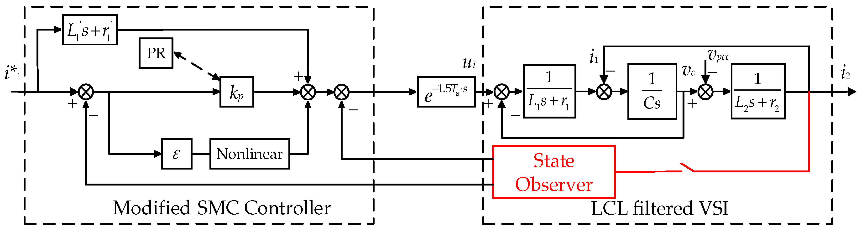
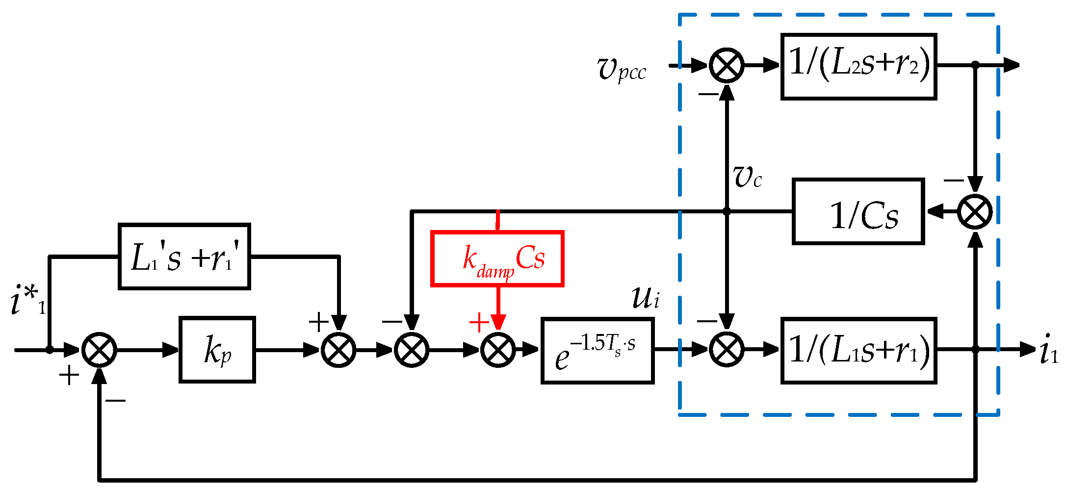
3.3. Modified SMC Controller with Active Damping

As explained previously, this section will provide a modified SMC controller with active damping to increase the control bandwidth and improve the robustness against the grid impedance variations based on Section 3.1 and Section 3.2. As inspired by a well-known active damping method, the capacitor voltage obtained by the state observer is added in the conventional SMC control loop. The modified control block diagram is shown in Figure 5.
The modified overall expression of the SMC switching function can be written in Equation (24):
{ u i α = L 1 k p s α + L 1 ε s a t ( s α ) + L 1 i 1 α · + r 1 i 1 α v c α + k d a m p C d v c α d t u i β = L 1 k p s β + L 1 ε s a t ( s β ) + L 1 i 1 β · + r 1 i 1 β v c β + k d a m p C d v c β d t
Then, the closed-loop transfer function of the modified SMC system is shown in Equation (25):
G c l o s e + a d ( s ) = I 1 ( s ) I 1 ( s ) = c 3 s 3 + c 2 s 2 + c 1 s + c 0 d 3 s 3 + d 2 s 2 + d 1 s + d 0
where:
c 3 = C L 2 L 1 c 2 = C L 2 k p + C L 2 r 1 + C L 1 r 2 c 1 = L 1 + C k p r 2 + C r 2 r 1 c 0 = k p + r 1 d 3 = C L 1 L 2 e 1.5 T s s d 2 = C L 2 k p + C L 2 k d a m p + C L 1 r 2 e 1.5 T s s + C L 2 r 1 e 1.5 T s s d 1 = L 2 + L 1 e 1.5 T s s + L 2 e 1.5 T s s + C k p r 2 + C k d a m p r 2 + C r 1 r 2 e 1.5 T s s d 0 = k p + r 2 + r 1 e 1.5 T s s + r 2 e 1.5 T s s
In order to analyze the performance of a modified SMC controller, the frequency responses of the open-loop transfer functions of the traditional SMC method and modified SMC method have been plotted, as shown in Figure 6. It can be seen that the resonance peak is damped when the capacitor voltage loop is added into the control loop.
To be clear, the eigenvalues of the modified closed-coop system in the z plane are provided in Figure 7. After adding the capacitor voltage loop in the control loop, the LCL poles are attracted inside the unity circle and the critical value of the proportional gain kp has increased to 12, which means the stability margin is enlarged and the bandwidth can be increased.

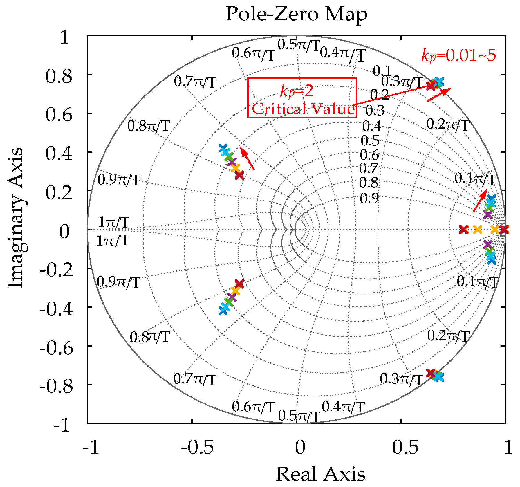
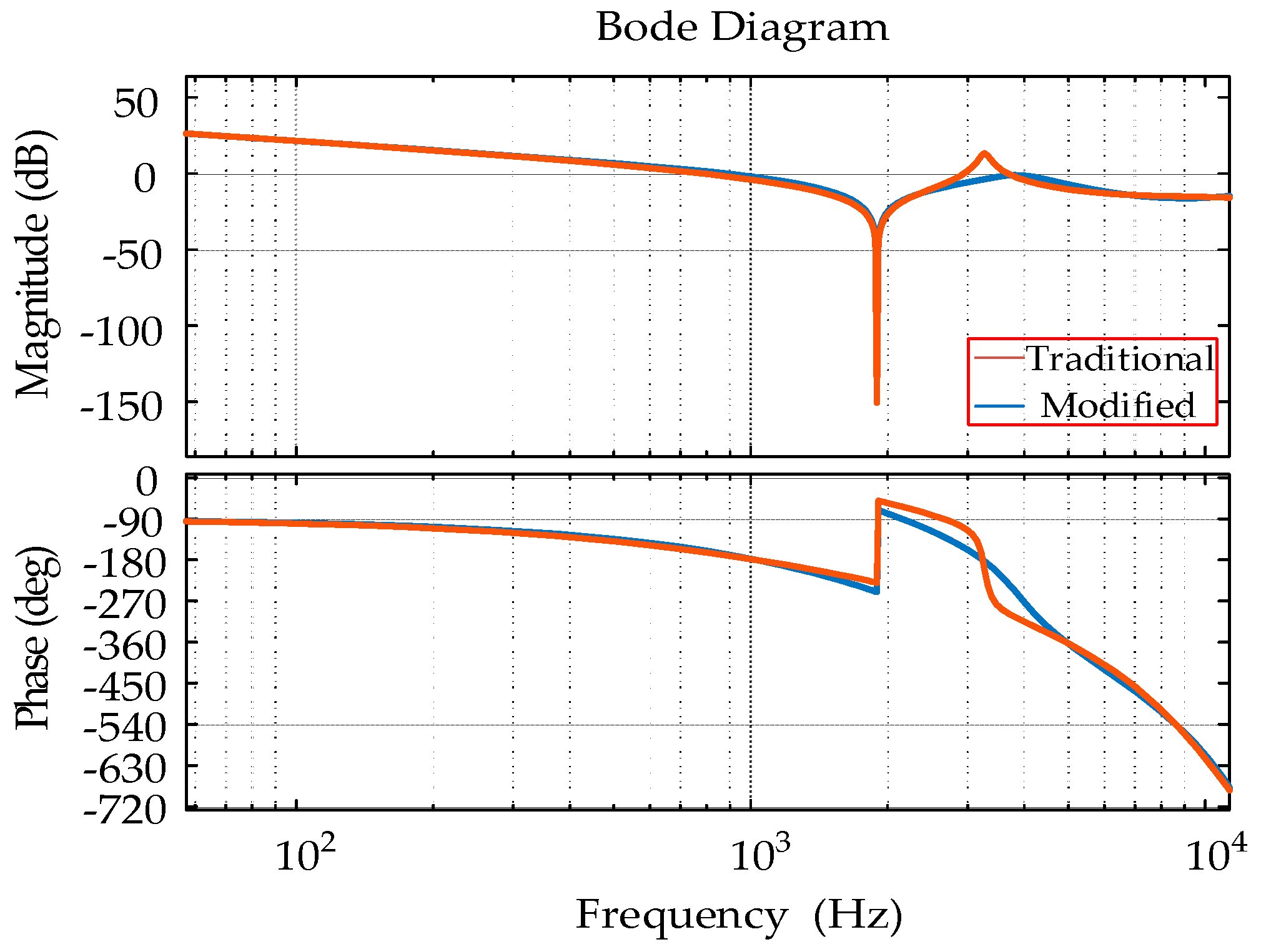
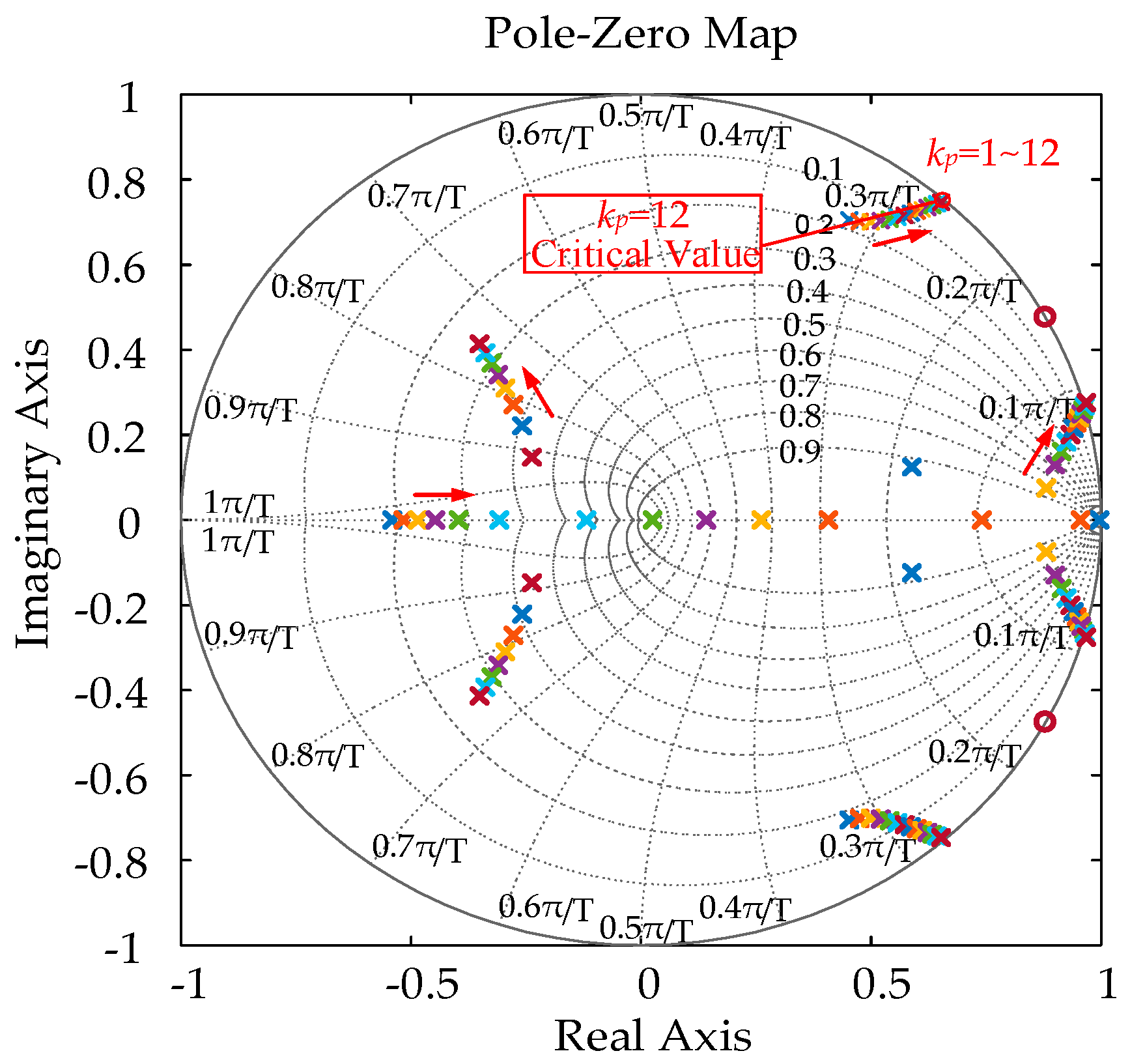
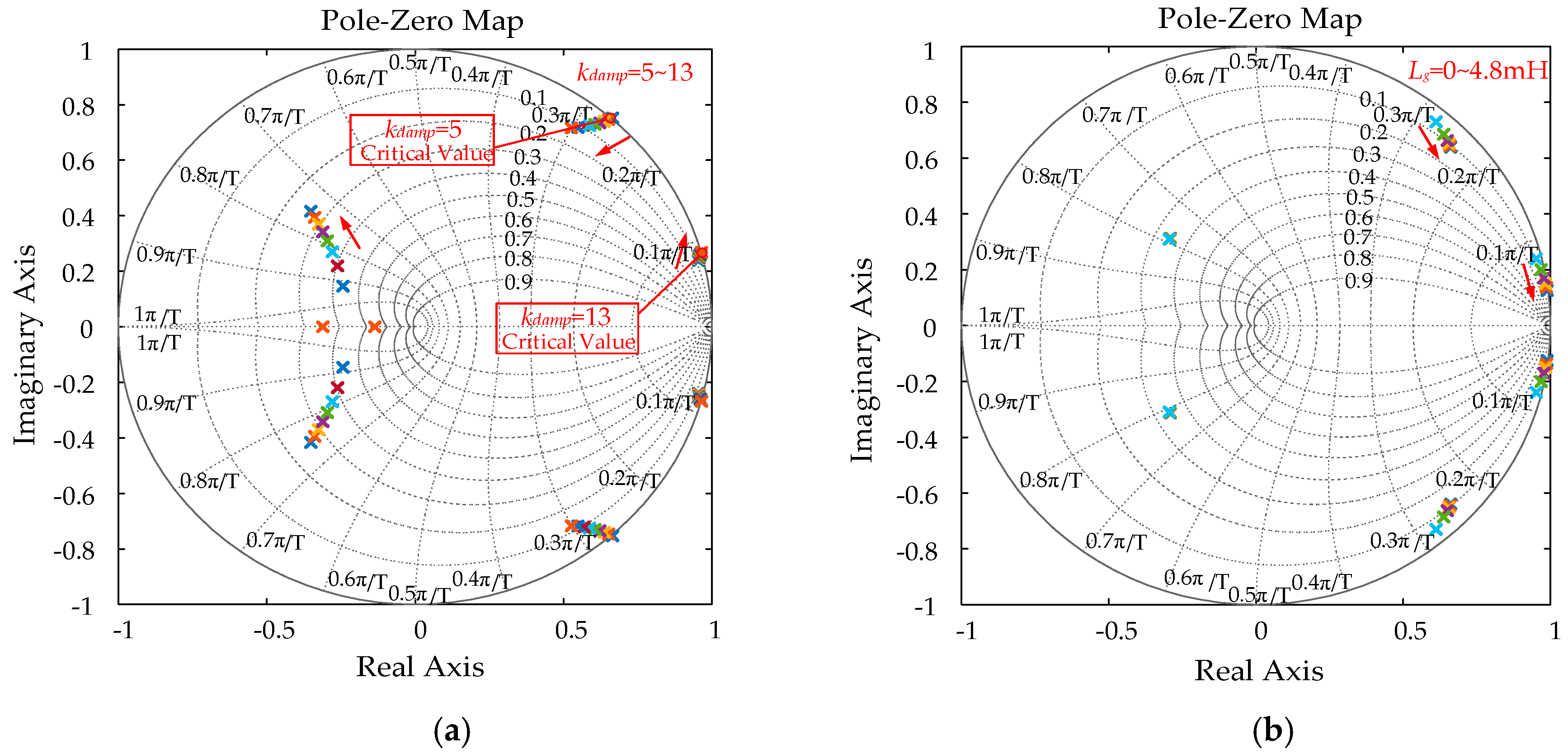
3.4. Stability Analysis

To prove the robustness of VSI using the proposed control method and to select the controller parameters, a stability analysis was performed in this part. The system stability is ensured if the poles of the closed-coop system are inside the unity circle in the z plane.
In order to operate the closed-loop system with a reasonable damping effect, all poles should be placed far away from the border of the unit circle in z plane. Considering the dynamic response and the bandwidth of the VSI system for PR harmonics compensation, the proportional gain of the PR controller kp is selected as 10. Figure 8a shows the root locus diagrams when the damping gain kdamp varies from 5 to 13. Hence, kdamp should be selected between the critical values to ensure a high damping effect and system robustness.
Figure 8b shows the movement of the closed-loop poles with different values of grid impedance Lg. With Lg increasing from 0 to 4.8 mH, the poles always move inside the unit circle, which shows good validity of the proposed control algorithm and proves that the system can be stabilized by using a modified SMC under a weak grid.

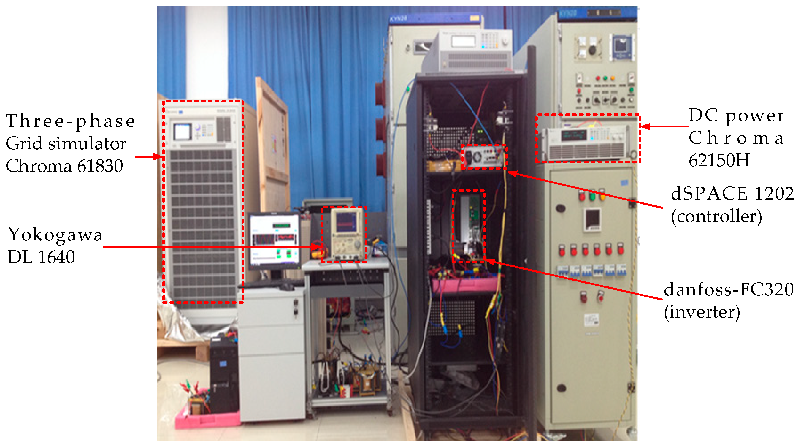
4. Experimental Results

In order to validate the effectiveness and performance of the proposed control algorithm, the experimental results are obtained on a 3 kW Danfoss FC302 converter tied to the grid through a LCL filter, as shown in Figure 9. Grid-side current and PCC voltage are sensed for a control strategy. The proposed control scheme was implemented in a digital signal processor dSPACE DS1202 controller with a sampling frequency of 12 kHz. The power grid and the DC voltage have been generated using a Chroma 61830 three-phase grid simulator and a Chroma 62150H-600S DC power supply, respectively. The grid voltage and grid-injected current waveforms were observed by Yokogawa DL 1640 digital oscilloscope. The implemented system is depicted in Figure 9 and parameters are listed in Table 1 and Table 2 for testing.
According to the analysis above, the proposed SMC method is simple and effective with less sensors. Three cases are discussed in the following experimental results: (1) the effect of the capacitor voltage loop; (2) behavior with changes in the reference current value and grid inductance variation; and (3) performance under grid voltage distortion.

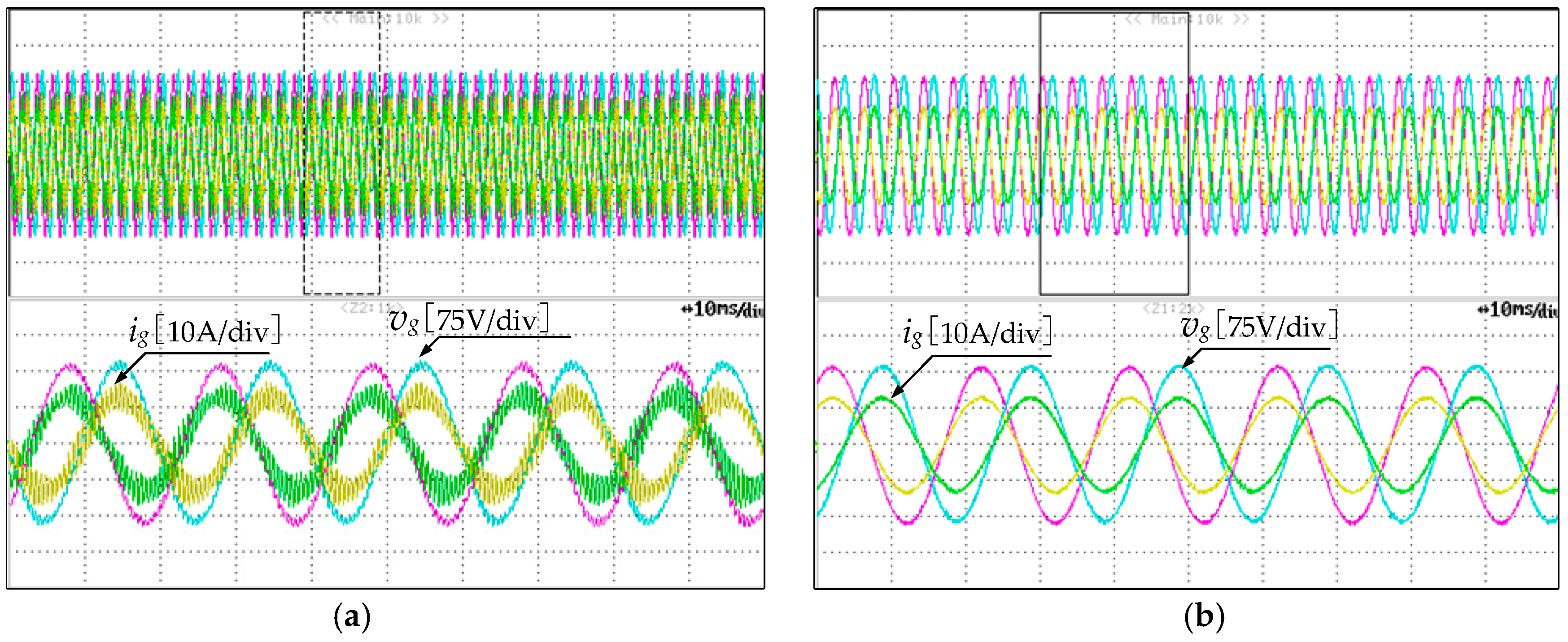
4.1. Test of Active Damping Effect

As discussed in previous sections, the modified SMC control with capacitor voltage loop feedback has a damping effect for LCL resonance. In this way, the system control bandwidth can be increased and the grid current can meet the harmonics compensation requirement with a PR controller. Figure 10a shows the experimental results of PCC voltages and grid currents for Phase a and b with kdamp = 0, kp = 10. It can be seen from the figure that the system is unstable with oscillations in the currents. Then, the experimental results in Figure 10b have shown that an active damping loop takes effect and the system is stable when the kdamp is changed to eight. After enabling the damping, the system becomes stable and the THD of the grid current is 2.5%. Figure 11 shows the PCC voltages and converter-side currents with the proposed SMC method. The state observer works well with the SMC control and the results verify the correctness of the control parameters selection.

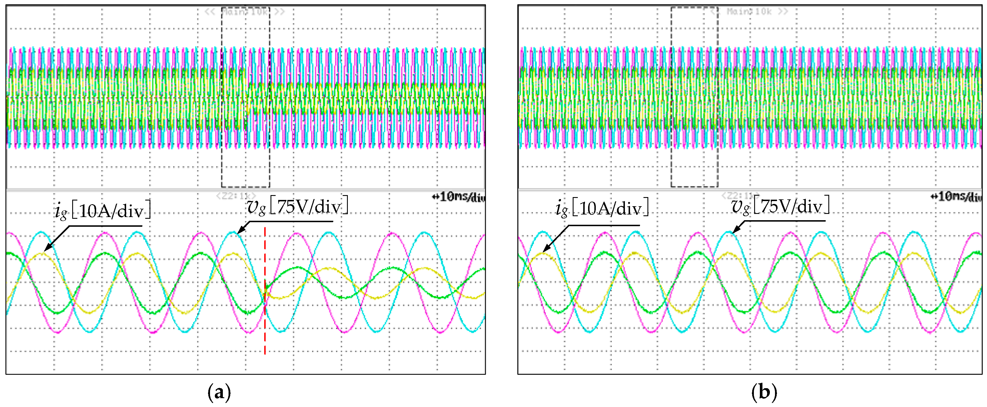
4.2. Performance of the Grid-Connected VSI against Sudden Changes in the Reference Current and Grid Inductance Variation

Figure 12a presents the grid current and PCC voltage waveforms of the grid-connected VSI when a sudden reference current change occurs, from full-load to half-load with the proposed SMC method. It presents a variation in the reference current i 1 from 12.8 A to 6.4 A. This result clearly demonstrates the effect of using a PR controller in achieving zero steady-state error and fast dynamic response in the grid current.
The performance of the grid-connected VSI under grid inductance variation with proposed SMC method is also presented in Figure 12b. In the test, the grid inductance is increased from 0–4.8 mH. As it can be seen, with the modified control method the system keeps stable even though it is in the weak grid. It can be concluded that all the roots are attracted inside the unit circle in accordance with the analysis in Section 3.4, which proves the high robustness of the control algorithm against grid inductance variations without a tuning algorithm.

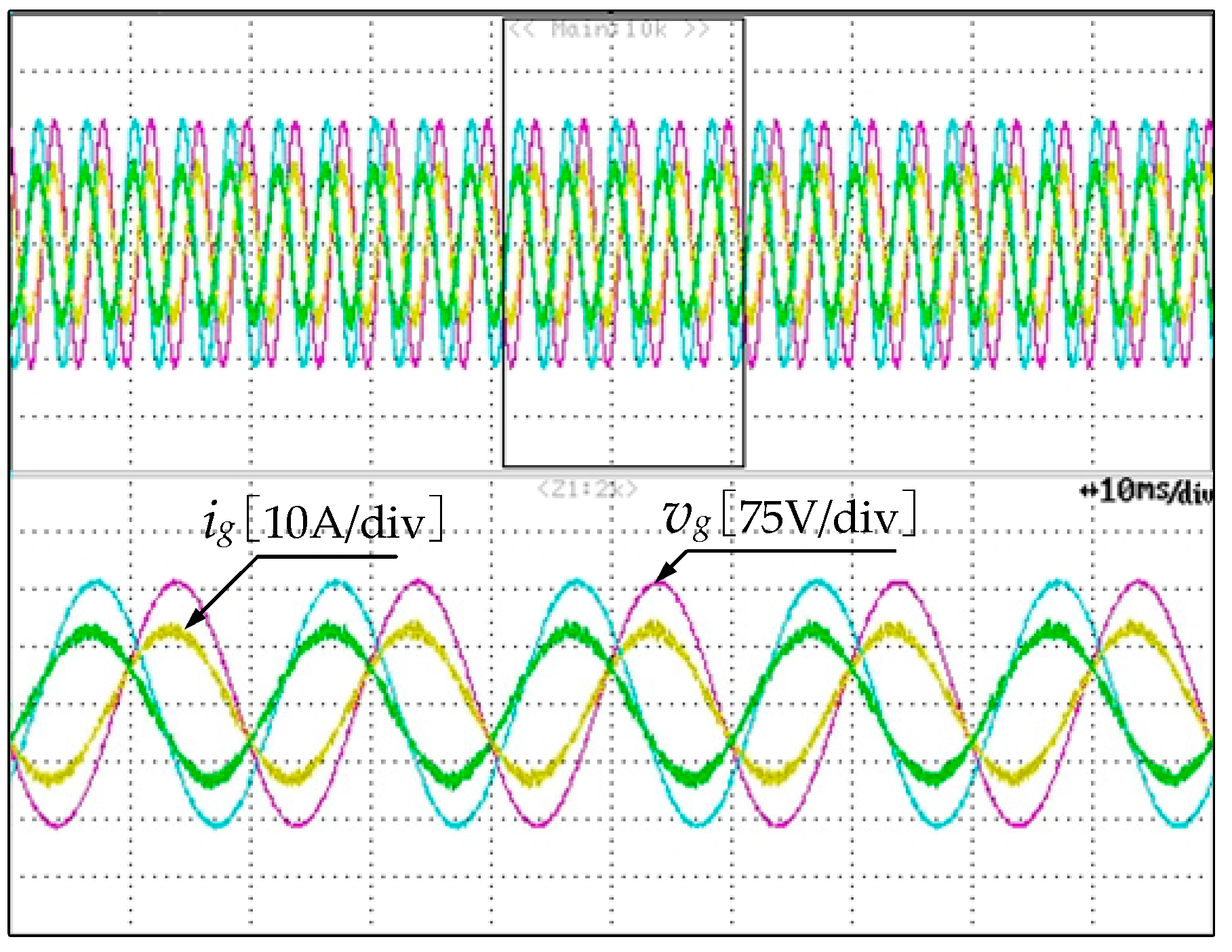
4.3. Test of the Grid-Connected VSI under Grid Distortion

Figure 13 shows the experimental steady-state results of PCC voltage and grid current of grid-connected VSI by the proposed control strategy under grid distortion. Even though the grid voltages are injected 3% for the third, fifth and seventh harmonic components, the grid current waveforms are still sinusoidal, realizing the good harmonic compensation and zero steady-state error by a PR controller.

5. Conclusions

In this paper, an observer-based sliding mode control for LCL-filtered grid-connected inverters with improved stability was presented. Traditionally, the implementation of a sliding mode control is always accompanied by multiple state variables feedback, which requires more sensors. The proposed control strategy can reduce two sensors by using a state observer. The state observer can be combined well with the discrete sliding mode control in digital implementation. In addition, the use of an estimated capacitor voltage can provide an active damping capability to the system by eliminating the LCL resonance. Furthermore, a detailed parameter design of the proposed SMC method was provided and analyzed when considering the digital discretization. The experimental results obtained from a 3 kW system shows that the proposed control strategy achieved a good performance, especially in its robustness against a wide range of grid inductance variations, and the state observer did not influence the control effect of the system.

Author Contributions

The individual contribution of each co-author with regards to the reported research and writing of the paper is as follows. M.H. and W.W. conceived the idea, H.L. performed data analysis and the simulation/experimental results, and all authors wrote the paper. All authors have read and approved the manuscript.

Funding

This research was funded by Shanghai Pujiang Talent Plan (Shanghai Science and Technology Commission), grant number 17PJ1403200.

Conflicts of Interest

The authors declare no conflicts of interest.

References

  1. Blaabjerg, F.; Teodorescu, R.; Liserre, M.; Timbus, A.V. Overview of control and grid synchronization for distributed power generation systems. IEEE Trans. Ind. Electron. 2006, 53, 1398–1409. [Google Scholar] [CrossRef]
  2. Gong, Z.; Wu, X.; Dai, P.; Zhu, R. Modulated model predictive control for MMC-based active front-end rectifiers under unbalanced grid conditions. IEEE Trans. Ind. Electron. 2019, 66, 2398–2409. [Google Scholar] [CrossRef]
  3. Zhang, Z.; Wu, W.; Shuai, Z.; Wang, X.; Luo, A.; Chung, H.S.; Blaabjerg, F. Principle and Robust Impedance-based design of grid-tied inverter with LLCL-Filter under wide variation of grid-reactance. IEEE Trans. Ind. Electron. 2018. [Google Scholar] [CrossRef]
  4. Liserre, M.; Teodorescu, R.; Blaabjerg, F. Stability of photovoltaic and wind turbine grid-connected inverters for a large set of grid impedance values. IEEE Trans. Ind. Electron. 2006, 21, 263–272. [Google Scholar] [CrossRef]
  5. Huang, M.; Wang, X.; Loh, P.C.; Blaabjerg, F. Active damping of LLCL -filter resonance based on LC -trap voltage or current feedback. IEEE Trans. Ind. Electron. 2015, 31, 2337–2346. [Google Scholar] [CrossRef]
  6. Yu, Y.; Li, H.; Li, Z.; Zhao, Z. Modeling and analysis of resonance in LCL-type grid-connected inverters under different control schemes. Energies 2017, 10, 104. [Google Scholar] [CrossRef]
  7. Figueres, E.; Garcera, G.; Sandia, J.; Gonzalez-Espin, F.; Calvo Rubio, J. Sensitivity study of the dynamics of three-phase photovoltaic inverters with an LCL grid filter. IEEE Trans. Ind. Electron. 2009, 56, 706–717. [Google Scholar] [CrossRef]
  8. Liu, Y.; Wu, W.; He, Y.; Lin, Z.; Blaabjerg, F.; Chung, H.S. An efficient and robust hybrid damper for LCL- or LLCL-based grid-tied inverter with strong grid-side harmonic voltage effect rejection. IEEE Trans. Ind. Electron. 2016, 63, 926–936. [Google Scholar] [CrossRef]
  9. Wu, W.; Liu, Y.; He, Y.; Chung, H.S.; Liserre, M.; Blaabjerg, F. Damping methods for resonances caused by LCL-filter-based current-controlled grid-tied power inverters: An overview. IEEE Trans. Ind. Electron. 2017, 64, 7402–7413. [Google Scholar] [CrossRef]
  10. Huang, M.; Wang, X.; Loh, P.C.; Blaabjerg, F. LLCL-filtered grid converter with improved stability and robustness. IEEE Trans. Power Electron. 2016, 31, 3958–3967. [Google Scholar] [CrossRef]
  11. Lorzadeh, I.; Abyaneh, H.A.; Savaghebi, M.; Bakhshai, A.; Guerrero, J.M. Capacitor current feedback-based active resonance damping strategies for digitally-controlled inductive-capacitive -inductive-filtered grid-connected inverters. Energies 2016, 9, 642. [Google Scholar] [CrossRef]
  12. Schiesser, M.; Wasterlain, S.; Marchesoni, M.; Carpita, M. A simplified design strategy for multi-resonant current control of a grid-connected voltage source inverter with an LCL filter. Energies 2018, 11, 609. [Google Scholar] [CrossRef]
  13. Shen, G.; Zhu, X.; Zhang, J.; Xu, D. A new feedback method for PR current control of LCL-filter-based grid-connected inverter. IEEE Trans. Ind. Electron. 2010, 57, 2033–2041. [Google Scholar] [CrossRef]
  14. He, Y.; Chung, H.S.; Ho, C.N.; Wu, W. Use of boundary control with second-order switching surface to reduce the system order for deadbeat controller in grid-connected inverter. IEEE Trans. Ind. Electron. 2016, 31, 2638–2653. [Google Scholar] [CrossRef]
  15. Mu, X.; Wang, J.; Wu, W.; Blaabjerg, F. A modified multifrequency passivity-based control for shunt active power filter with model-parameter-adaptive capability. IEEE Trans. Ind. Electron. 2018, 65, 760–769. [Google Scholar] [CrossRef]
  16. Shu, Z.L.; Liu, M.; Zhao, L.; Song, S.S.; Zhou, Q.; He, X.Q. Predictive harmonic control and its optimal digital implementation for MMC-based active power filter. IEEE Trans. Ind. Electron. 2016, 63, 5244–5254. [Google Scholar] [CrossRef]
  17. Falkowski, P.; Sikorski, A. Finite control set model predictive control for grid-connected AC–DC converters with LCL filter. IEEE Trans. Ind. Electron. 2018, 65, 2844–2852. [Google Scholar] [CrossRef]
  18. Jin, W.; Li, Y.; Sun, G.; Bu, L. H∞ repetitive control based on active damping with reduced computation delay for LCL-type grid-connected inverters. Energies 2017, 10, 586. [Google Scholar] [CrossRef]
  19. Yoon, S.; Lai, N.B.; Kim, K. A systematic controller design for a grid-connected inverter with LCL filter using a discrete-time integral state feedback control and state observer. Energies 2018, 11, 437. [Google Scholar] [CrossRef]
  20. Hao, X.; Yang, X.; Liu, T.; Huang, L.; Chen, W. A sliding-mode controller with multiresonant sliding surface for single-phase grid-connected VSI with an LCL filter. IEEE Trans. Ind. Electron. 2013, 28, 2259–2268. [Google Scholar] [CrossRef]
  21. Vieira, R.P.; Martins, L.T.; Massing, J.R.; Stefanello, M. Sliding mode controller in a multiloop framework for a grid-connected VSI with LCL filter. IEEE Trans. Ind. Electron. 2017, 65, 4714–4723. [Google Scholar] [CrossRef]
  22. Guzman, R.; de Vicuña, L.G.; Castilla, M.; Miret, J.; de la Hoz, J. Variable structure control for three-phase LCL-filtered inverters using a reduced converter model. IEEE Trans. Ind. Electron. 2017, 65, 5–15. [Google Scholar] [CrossRef]
  23. Guzman, R.; de Vicuña, L.G.; Castilla, M.; Miret, J.; Martín, H. Variable structure control in natural frame for three-phase grid-connected inverters with LCL filter. IEEE Trans. Ind. Electron. 2018, 33, 4512–4522. [Google Scholar] [CrossRef]
  24. Altin, N.; Ozdemir, S.; Komurcugil, H.; Sefa, I. Sliding-mode control in natural frame with reduced number of sensors for three-phase grid-tied LCL-interfaced inverters. IEEE Trans. Ind. Electron. 2019, 66, 2903–2913. [Google Scholar] [CrossRef]
  25. Guzman, R.; de Vicuña, L.G.; Morales, J.; Castilla, M.; Miret, J. Model-based control for a three-phase shunt active power filter. IEEE Trans. Ind. Electron. 2016, 63, 3998–4007. [Google Scholar] [CrossRef]
  26. Komurcugil, H.; Ozdemir, S.; Sefa, I.; Altin, N.; Kukrer, O. Sliding-mode control for single-phase grid-connected LCL-filtered VSI with double-band hysteresis scheme. IEEE Trans. Ind. Electron. 2016, 63, 864–873. [Google Scholar] [CrossRef]
  27. Wang, B.; Xu, Y.; Shen, Z.; Zou, J.; Li, C.; Liu, H. Current control of grid-connected inverter with LCL filter based on extended-state observer estimations using single sensor and achieving improved robust observation dynamics. IEEE Trans. Ind. Electron. 2017, 64, 5428–5439. [Google Scholar] [CrossRef]
  28. Kukkola, J.; Hinkkanen, M.; Zenger, K. Observer-based state-space current controller for a grid converter equipped with an LCL filter: Analytical method for direct discrete-time design. IEEE Trans. Ind. Appl. 2015, 51, 4079–4090. [Google Scholar] [CrossRef]
  29. Kukkola, J.; Hinkkanen, M. Observer-based state-space current control for a three-phase grid-connected converter equipped with an LCL filter. IEEE Trans. Ind. Appl. 2014, 50, 2700–2709. [Google Scholar] [CrossRef]
  30. Kukkola, J.; Hinkkanen, M. State observer for grid-voltage sensorless control of a converter under unbalanced conditions. IEEE Trans. Ind. Appl. 2018, 54, 286–297. [Google Scholar] [CrossRef]
Figure 1. Three-phase grid connected VSI with LCL filter and controller.
Energies 12 01421 g001
Figure 2. Basic SMC control scheme diagram of grid connected VSI in αβ-frame.
Energies 12 01421 g002
Figure 3. Closed-loop poles locations of G1(s) when kp varies from 0.01 to 5.
Energies 12 01421 g003
Figure 4. Discretization control diagram of state observer closed-loop system of grid-connect VSI.
Energies 12 01421 g004
Figure 5. Control block of the modified SMC of grid-connected VSI in αβ-frame.
Energies 12 01421 g005
Figure 6. Bode plots of open-loop control gain with traditional and modified control methods.
Energies 12 01421 g006
Figure 7. System poles of modified SMC when kp varies from 1 to 12.
Energies 12 01421 g007
Figure 8. Root locus diagrams when (a) the damping gain kdamp varies; (b) grid impedance Lg varies.
Energies 12 01421 g008
Figure 9. LCL-filtered three-phase grid-connected VSI experimental prototype.
Energies 12 01421 g009
Figure 10. Measured waveforms of PCC voltages and grid currents (a) without active damping; (b) with active damping.
Energies 12 01421 g010
Figure 11. Measured waveforms of PCC voltages and converter-side currents.
Energies 12 01421 g011
Figure 12. Measured waveforms of PCC voltages and grid currents with proposed SMC when (a) the reference current changes; (b) the grid inductance varies.
Energies 12 01421 g012
Figure 13. Measured waveforms of PCC voltages and grid currents with proposed SMC under distorted grid voltage.
Energies 12 01421 g013
Table 1. System parameters.
SymbolValue
DC link voltage Udc350 V
Grid voltage vg 110 V(RMS)
Sampling frequency fs 12 kHz
Switching frequency fsw 12 kHz
Inverter-side inductance L11.2 mH
Filter capacitance C 6 μF
Grid-side inductance L2 1.2 mH
Inductor resistors r1, r20.2 Ω, 0.2 Ω
Table 2. Controller parameters for experimental results.
SymbolValue
Coefficient of control kp10
Coefficient of control kr800
Coefficient of control kdamp8

