Article

Distributed Economic Power Dispatch and Bus Voltage Control for Droop-Controlled DC Microgrids

1
School of Electrical Engineering, Zhengzhou University, Zhengzhou 450001, China
2
Department of Electrical and Computer Engineering, The University of Alabama, Tuscaloosa, AL 35487, USA
*
Author to whom correspondence should be addressed.
These authors contributed equally to this work.
Energies 2019, 12(7), 1400; https://doi.org/10.3390/en12071400
Submission received: 4 March 2019 / Revised: 29 March 2019 / Accepted: 9 April 2019 / Published: 11 April 2019
(This article belongs to the Section A1: Smart Grids and Microgrids)

Abstract

:
This paper proposes a distributed economic power dispatch (EPD) and bus voltage control solution for droop-controlled DC microgrids. For the proposed solution, a local power controller and a local voltage controller are added for each distributed generator (DG) to overcome the limitations of the conventional droop control. The power controller generates the first voltage correction term by comparing the local output power of DG with the reference instruction generated by the proposed distributed EPD algorithm, and thus, it can reduce the operation cost of the microgrid by optimally sharing the load demand among all the participating DGs. The voltage controller generates the second voltage correction term by comparing the nominal DC bus voltage value with the average bus voltage generated by the proposed distributed average bus voltage observation (ABVO) algorithm, and thus, it can realize the global bus voltage regulation of the DC microgrid. In contrast with conventional solutions, the control solution can distribute the computational and communication burdens among all the DGs working in parallel, which is more flexible, scalable, and robust against single-point failure. The effectiveness of the proposed control solution is demonstrated through simulation studies.

1. Introduction

The microgrid concept is receiving considerable interest, as it can integrate a large amount of DGs into the power grid in a more environmentally-friendly and reliable way [1]. Based on the voltage and current types, microgrids can be categorized into three categories, i.e., AC microgrids, DC microgrids, and hybrid AC/DC microgrids.
DC microgrids are gaining more and more attention due to the competitive advantages they provide over AC microgrids [2,3]. Firstly, DC microgrids can integrate the renewable energy sources (i.e., wind-power, photovoltaic), storage units (i.e., batteries, ultra-capacitors), and DC loads more efficiently, because the AC/DC and DC/AC conversion stages are avoided [4,5]. Secondly, there are no issues with frequency regulation and reactive power flow for the DC microgrids [6,7].
In DC microgrids, the droop control method is typically applied to regulate the output voltage of converter-interfaced DGs [3,8,9,10,11]. However, there are some drawbacks of conventional droop control methods [12,13]. Firstly, similar to the reactive power sharing in AC microgrids, the current sharing accuracy is degraded due to the voltage droop across the line resistance. Secondly, DC bus voltage deviation exists and varies with the load demand.
Several centralized control strategies have been proposed to deal with the aforementioned issues [14,15,16], which require central controllers to collect and process the global information. However, the centralized solutions are sensitive to single-point failure [17] as they require a central controller to communicate with all the DGs in the microgrid to collect information and to process a large amount of data.
Distributed control strategies are also proposed to deal with the aforementioned issues, which only require the local information or limited communication [17,18,19,20,21,22]. A coordinated adaptive droop control was proposed for a DC microgrid to optimize its power distribution [18]. However, the global bus voltage regulation of the DC microgrid was not considered, and a current regulator was needed to estimate the system power imbalance. The estimated value may deviate from the real value, which will degrade the performance of the proposed solution. A consensus-based control scheme was proposed to solve the distributed economic dispatch problem for distributed power systems [19]. However, a leader agent was needed to calculate the goal attraction terms, making it have a certain centralized control nature instead of a fully-distributed solution. Consensus algorithms have been proposed to be embedded in generation units to allocate power among connected buses [22]. However, a leader agent was also required for this solution. A distributed economic dispatch algorithm was proposed for a microgrid [20]. However, the load demand and exchange power of the tie-line needed to be discovered first in a centralized or distributed way. A distributed strategy based on a distributed dynamic programming algorithm was proposed for the economic power dispatch (EPD) problem [17]. However, the load demand needed also to be discovered first. A distributed approach was proposed for frequency control and optimal economic dispatch of power generators [21]. However, the solution may cause unexpected oscillation because the power mismatch is unavoidable during the optimization process. Moreover, in most of the distributed EPD algorithms [17,19,20,22], the load nodes and the uncontrollable generator nodes need to be designed with the capability of communication, since their information is required for the power imbalance estimation, which increases the complexity and costs of the system.
In this paper, a distributed optimal bus voltage control for droop-controlled DC microgrids is proposed. The proposed method is augmented with two additional correction terms to provide economic load sharing and global bus voltage regulation, respectively. These two correction terms are generated based on the distributed consensus-based EPD algorithm and average bus voltage observation algorithm proposed in this paper. Compared to the centralized solutions, the distributed solutions are more flexible, scalable, and robust against single-point failure [23], as they can distribute the computational and communication burdens among all the DGs working in parallel.
The main contributions of this paper include the following: (1) The gap between the secondary voltage control level and tertiary EPD control level is bridged by simultaneously realizing the economic load sharing and the global bus voltage regulation. (2) The operating cost of a DG microgrid is reduced as it can optimally sharing the loads among all the participating DGs according to the power generation cost of each DG in almost real time. (3) The proposed method can work in a fully-distributed way without a central controller or a lead agent and only requires communication among neighboring agents. (4) With the help of droop control in the primary level, information about load nodes and uncontrollable generator nodes is not required. (5) Compared to a centralized control method, the reliability of the proposed strategy is improved (6) An integrated simulation-based study that contains multiple DGs, multiple control levels, and agent-based control and communication is implemented to understand the behavior of the proposed method.
This paper is organized as follows. In Section 2, the problem formulation is presented. In Section 3, the distributed consensus-based EPD algorithm and average bus voltage observation (ABVO) algorithm are presented. In Section 4, the simulation results are provided. Finally, this paper is concluded in Section 5.

2. Problem Formulation

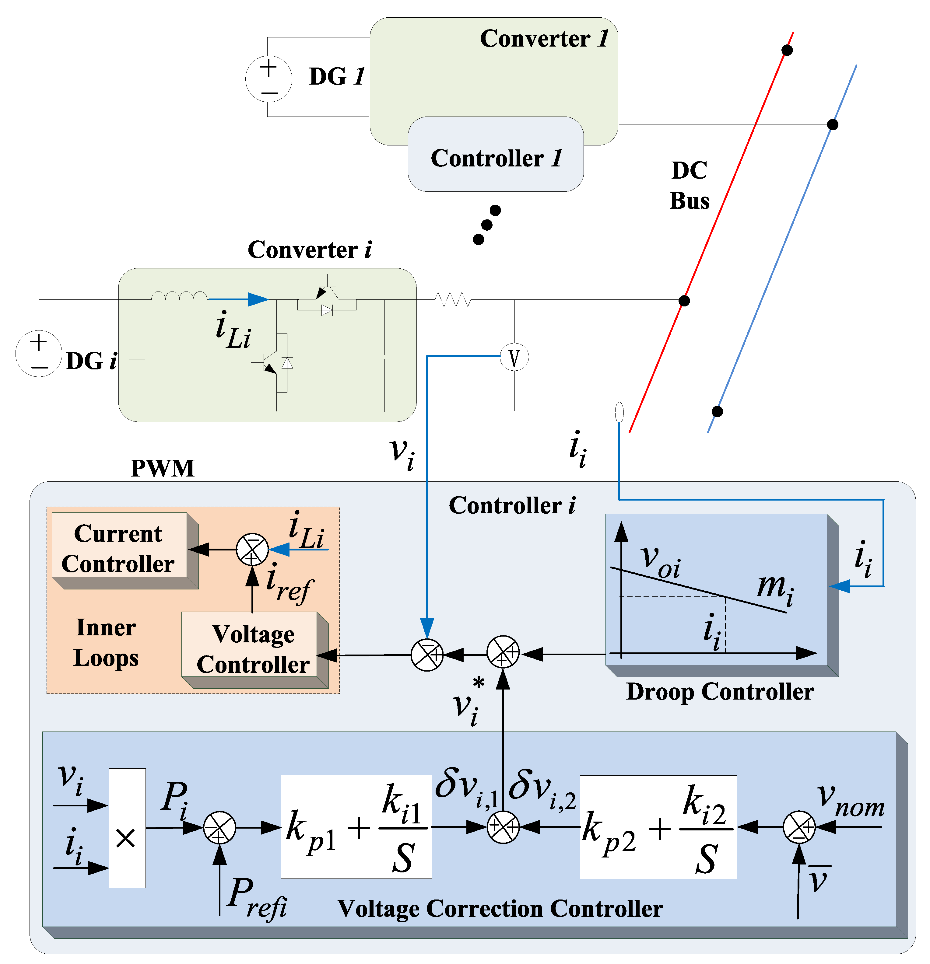
2.1. Conventional Droop Control Method in DC Microgrids

The droop control method is typically applied to regulate the output voltage of converter-interfaced DGs [3,8,9,10,11]. Generally, the voltage-current droop control shown in (1) is commonly used.
v i * = v o i i i m i
where i is the index of droop-controlled DGs, v i * is the reference value of DC output voltage that is sent to the inner voltage control loop of the ith DG, v o i is the preset value of the DC voltage, and i i and m i are the output current and the droop-coefficients of the ith DG, respectively.
As shown in Figure 1, the conventional control diagram of converter-interfaced DGs in DC microgrid includes the droop controller and inner voltage and current controllers. The droop coefficients affect the system stability and current sharing accuracy. In general, with a higher droop coefficient, the accuracy of current sharing will be better, while the voltage deviation will be higher [24]. Thus, there exists a trade-off between the accuracy of current sharing and voltage deviation when choosing the values of droop coefficients.

2.2. Proposed Optimal Bus Voltage Control

In order to overcome the drawbacks of the conventional droop control method, an optimal bus voltage control method is proposed as shown in Figure 1. The voltage reference instruction for the local controller of the ith DG is expressed as:
v i * = v o i i i m i + δ v i , 1 + δ v i , 2 δ v i , 1 = ( k p 1 + k i 1 S ) ( P r e f i P i ) δ v i , 2 = ( k p 2 + k i 2 S ) ( v n o m v ¯ )
where i represents the DG index, δ v i , 1 and δ v i , 2 represent the first and the second voltage correction terms, respectively, k p 1 , k i 1 , k p 2 , k i 2 are the parameters of PI controllers, P r e f i is the reference value of power control demands generated by the proposed EPD algorithm (Section 3), P i is the locally-measured active power, v n o m represents the preset value of nominal DC bus voltage, and v ¯ represents the average bus voltage generated by the proposed ABVO algorithm (Section 3).
As shown in Figure 1, the conventional droop control is augmented with two terms to formulate the proposed control method. The purpose of terms δ v i , 1 and δ v i , 2 is to provide economic load sharing and global bus voltage control, respectively. With the proposed control solution, the global bus voltage regulation and EPD can be realized simultaneously as explained in Section 3. In this paper, the term δ v i , 1 can be generated through a PI controller, while P r e f i is acquired distributedly through the proposed EPD algorithm. Thus, all DGs can operate at the EPD state according to the power generation cost of each DG through distributed cooperation with each DG’s neighbors. Similarly, the term δ v i , 2 can be generated through a PI controller, while v ¯ is acquired distributedly through the proposed ABVO algorithm. Thus, the bus voltage deviation can be eliminated through distributed cooperation with each DG’s neighbor. The detail of the proposed EPD and ABVO algorithms is discussed in Section 3.

3. Distributed Consensus-Based EPD and ABVO Algorithms

The proposed agent-based and distributed control architecture for a DC microgrid is illustrated in Figure 2. Each DG in the DC microgrid is equipped with an agent that has the functionalities of acquiring the information of its local DG, implementing the EPD and ABVO algorithms by exchanging data with its neighbors, and generating the voltage correction terms.

3.1. Graph Theory Review

In Figure 2, each agent is represented by a vertex, and the communication links between the agents are represented by edges in this paper. Thus, the microgrid system is generally a cyber-physical system [4,25]. In order to model the communication topology of a DC microgrid efficiently, denote G = ( V , E ) as a graph with pair sets of ( V , E ) , where V = { 1 , 2 , , n } is a set of vertices connected through a set of edges E V × V . The communication link does not need to have the same topology as its physical DC microgrid. In an undirected graph, vertices i and j are called to be connected if it contains a path between i and j. Graph G is called to be connected if and only if there exists at least a path between any two vertices.

3.2. Distributed Consensus Algorithm

Define elements d i , j of the matrix D R N × N that is associated with a connected graph G as [26]:
d i , j = 2 n i + n j + ε j N i 1 j N i 2 n i + n j + ε i = j 0 otherwise
where n i and n j represent the number of neighbors for agents i and j, respectively, ε represents a small number (it affects the convergence speed of the proposed algorithm, as described in Section 4), and N i represents the set containing the indices of agents that communicate with agent i.
Consider the following discrete-time system:
u i ( k + 1 ) = j { i , N i } d i , j u i ( k )
where u i ( k ) represents the state variables associated with agent i at time step k.
Based on the distributed consensus algorithm [26,27], the compact form of (4) has the following property:
lim k D k μ = μ 0 1
According to (5), all the state variables of each agent will converge to the same value, which depends on the initial values.
Considering the definition of d i , j , the compact form of (4) also has the following property:
( D ) k μ = μ , k = 1 , 2 , ,
Equation (6) means that the summation of all state variables in the discrete-time system (4) is preserved during each iteration.
According to the definition of d i , j , D is related to the communication topology of the agents and ε . Thus, the convergence speed of (4) depends on the communication topology of the agents and the value of ε .

3.3. Distributed Consensus-Based EPD Algorithm

Generally, there are multiple DGs with different generation cost functions in a DC microgrid. The power generation cost is usually approximated by the following quadratic function [17,28]:
C i ( P i ) = a i P i 2 + b i P i + c i
where a i > 0 , b i , c i are the power generation cost coefficients of the ith DG and P i is the output power of the ith DG.
According to (7), the incremental cost of the ith DG is 2 a i P i + b i . Both the generation cost and the increment cost are increased with the increase of generated power. Furthermore, as the increment cost is proportional to the generated power, the generation cost will increase with the increase of the generated power until the DG reaches its maximum power output capacity.
Considering the power generation constraint and the power balance constraint of each DG, the reference values for EPD can be acquired by solving the following problem:
Min C = i = 1 n C i ( P r e f i ) s . t . P i ¯ P r e f i P ¯ i i = 1 n P r e f i = P L o a d
where P r e f i represents the reference value for the EPD of the ith DG, P i ¯ and P i ¯ represent the lower and upper bounds of the ith DG, respectively, and P L o a d represents the load demand in the DC microgrid.
The problem shown in (8) can be easily solved by the traditional gradient descent algorithm or a population-based optimization algorithm [29] in a centralized framework. However, in order to solve this problem in a distributed way, some distributed algorithms need to be applied and developed. According to the equal incremental cost criterion, the solution of the convex optimization problem of (8) satisfies the following conditions [17].
2 a i P r e f i + b i = λ * if P i ¯ < P r e f i < P ¯ i 2 a i P r e f i + b < λ * if P r e f i = P ¯ i 2 a i P r e f i + b > λ * if P r e f i = P i ¯
where λ * represents the optimal incremental cost.
Assume that all DGs have no power generation constraints. According to the distributed consensus algorithm (4) and the equal incremental cost criterion (9), the reference values for EPD can be acquired by solving (8) through the following distributed EPD algorithm.
P r e f i ( 0 ) = P i ( 0 ) λ i ( 0 ) = 2 a i P r e f i ( 0 ) + b i λ i ( k + 1 ) = j { i , N i } d i , j λ j ( k ) P r e f i ( k + 1 ) = 1 2 a i λ i ( k + 1 ) 1 2 a i b i
where P i ( 0 ) represents the locally-measured output power of the ith DG at the beginning of the EPD algorithm. In the islanded DC microgrid, the generated power of all the DGs and the load are always balanced. Thus, i = 1 n P i ( 0 ) = P L o a d .
According to the equal increment cost criterion [17], if the algorithm shown in (10) can converge to the optimal solution of the EPD problem shown in (8), it should satisfy the following two conditions: (a) the increment cost for each DG λ i should converge to the same value; (b) the constraint of power balance should always be satisfied.
Thus, based on the above two conditions, the convergence and the optimality of algorithm (10) is demonstrated below.
(a) The increment cost of each DG λ i converges to the same value.
In order to analyze the convergence and optimality of the above algorithm, (10) is rewritten in the following compact form:
P r e f ( 0 ) = P ( 0 )          (11a) λ ( 0 ) = A P r e f ( 0 ) + B          (11b) λ ( k + 1 ) = D λ ( k )          (11c) P r e f ( k + 1 ) = A 1 λ ( k + 1 ) A 1 B          (11d)
where P r e f = [ P r e f 1 , P r e f 2 , , P r e f n ] T , P ( 0 ) = [ P 1 ( 0 ) , P 2 ( 0 ) , , P n ( 0 ) ] T , λ = [ λ 1 , λ 2 , , λ n ] , A = d i a g ( [ 2 a 1 , 2 a 2 , , 2 a n ] ) , B = [ b 1 , b 2 , , b n ] T , A 1 = d i a g ( [ 1 2 a 1 , 1 2 a 2 , , 1 2 a n ] ) .
Comparing (11c) with (5), we can conclude that all the elements of λ will converge to the same value according to the distributed consensus algorithm. Thus, Condition (a) is satisfied for Algorithm (10).
(b) The constraint of power balance should always be satisfied.
Define Δ P r e f ( k + 1 ) = P r e f ( k + 1 ) P r e f ( k ) , and according to (6), (11c), and (11d), the following condition must be satisfied.
Δ P r e f ( k + 1 ) = A 1 D λ ( k ) A 1 λ ( k ) = 0 , k = 1 , 2 , ,
It should be noted that, in the islanded DC microgrid, the generated power of all the DGs and the load are always balanced. Thus, i = 1 n P i ( 0 ) = P L o a d . In addition, according to (11a), we can conclude that P r e f ( 0 ) = P ( 0 ) = P L o a d ; the power balance constraint must be satisfied in each iteration. Thus, Condition (b) is satisfied for Algorithm (10).
In conclusion, the algorithm shown in (10) can converge to the optimal solution of the EPD problem shown in (8).
Based on the above analysis, the reference values for EPD can be acquired distributedly by using the distributed algorithm shown in (10). However, the power generation constraints of all the DGs are not considered in (10).
In order to deal with the power generation constraints of the DGs, the distributed EPD algorithm shown in (10) is redesigned as the following form [30]:
P r e f i ( 0 ) = P i ( 0 ) λ i ( 0 ) = 2 a i P r e f i ( 0 ) + b i e i ( 0 ) = 0 λ i ( k + 1 ) = j { i , N i } d i , j λ j ( k ) + ξ e i ( k ) P r e f i ( k + 1 ) = ψ ( λ i ( k + 1 ) ) e i ( k + 1 ) = j { i , N i } d i , j e j ( k ) ( P r e f i ( k + 1 ) P r e f i ( k ) )
where ξ is the learning speed that influences the convergence speed of (13), e i is the feedback term, ψ ( ) is a piecewise function, as the following:
ψ i ( λ i ) = P ¯ i if λ i > λ ¯ i 1 2 a i λ i ( k + 1 ) 1 2 a i b i if λ i ¯ λ i λ ¯ i P i ¯ if λ i < λ i ¯
where λ ¯ i = 2 a i P ¯ i + b i and λ i ¯ = 2ai λ i ¯ + b i .
Define E = [ e 1 , e 2 , , e n ] T and ρ = d i a g ( [ ρ 1 , ρ 2 , , ρ n ] ) where ρ i = 1 2 a i if λ i ¯ λ i λ ¯ i otherwise ρ i = 0 corresponding to the three conditions shown in (14). Thus, the following composite format can be derived according to (13).
λ ( k + 1 ) E ( k + 1 ) = D ξ I ρ ( I D ) D ξ ρ λ ( k ) E ( k ) = H λ ( k ) E ( k )
According to (15), the EPD algorithm will be divergent if some of the eigenvalues of H lie outside of a unit circle. Thus, the stability condition of matrix H is to make the eigenvalues of H lie within a unit circle.
It should be noted that ρ i is a variable that is associated with the leading coefficient of the cost function (7), i.e., a i and the power generation constraint of the according DG. If ρ i is determined according to the above condition, it will not be redesigned again. Only ξ in (15) and ε in (3) need to be properly designed. Although, ρ i may affect the convergence speed of (15), the stability of (15) can be guaranteed if the parameters ξ and ε are properly designed with a certain robustness. For example, without loss of generality, we assume that at least one ρ i is nonzero. Then, ξ in (15) and ε in (3) can be properly designed to make the eigenvalues of H lie in an open unit circle, and P r e f i ( k ) in Algorithm (13) will converge to the optimal solution of (8). The convergence speed of distributed EPD shown in (13) depends on the second largest eigenvalue of H . According to this rule, the values for parameter ξ and ε can be properly designed.
The algorithm, proposed in [30], is based on a strongly-connected communication graph; the learning gain was designed by solving a complex LMIproblem; and the robustness of agent loss and the scalability were not considered. In this paper, the communication graph was bidirectional; the relation between the convergence speed of the proposed algorithm and the parameters ξ and ε were theoretical analyzed; and a simple rule was given for the selection of these parameters by calculating the eigenvalue of H.
In this paper, the line resistances were not considered for the proposed EPD algorithm since the problem will be too time consuming when the line resistance is considered, especially by a distributed algorithm. Generally, line resistances of a microgrid are not considered for such distributed algorithms, as reported in many previously-published articles [17,31,32]. Furthermore, a microgrid usually has relatively large line capacities compared to the distributed and small-scale generation units and loads within a microgrid. Therefore, congestion in a microgrid does not easily occur. In order to improve the speed of the proposed algorithm and also due to the above practical DG network nature, the line flow constraints were not considered.

3.4. Distributed Consensus-Based ABVO Algorithm

In order to provide global bus voltage regulation, we designed the proposed ABVO algorithm to acquire the average bus voltage of a DC microgrid. Based on the distributed consensus (4), the distributed ABVO algorithm is designed as:
v ¯ i ( 0 ) = v i ( 0 ) v ¯ i ( k + 1 ) = j { i , N i } d i , j v ¯ j ( k )
where v i ( 0 ) represents the locally-measured bus voltage of the ith DG at the beginning of the ABVO algorithm during each sampling time interval, v ¯ i ( k ) represents the observed average bus voltage at the k th iteration by the ith agent, and k represents the number of iterations. The above ABVO algorithm will be carried out for one iteration when the according information is updated through communication with its according neighboring agents. It will take a few milliseconds for each iteration, as explained in the last paragraph of Section 4.1.
In order to analyze the above algorithm, (16) is rewritten as the following compact form:
V ¯ ( 0 ) = V ( 0 ) V ¯ ( k + 1 ) = D V ¯ ( k )
where V ¯ = [ v ¯ 1 , v ¯ 2 , , v ¯ n ] T and V = [ v 1 , v 2 , , v n ] T .
According to the properties of the distributed consensus algorithm shown in (5) and (6), all the elements of V ¯ will converge to a same value, and the summation of all the elements of V ¯ is preserved during each iteration. Thus, all the agents will acquire the average bus voltage of the DC microgrid in a distributed way through the proposed ABVO algorithm.
Similar to the distributed EPD algorithm, the convergence speed of the distributed ABVO algorithm shown in (16) depends on the second largest eigenvalue of D . According to this rule, the values for parameter ε can be properly designed.

3.5. Algorithm Implementation

Figure 3 presents the detailed configuration and implementation of the proposed, agent-based EPD and ABVO algorithms in a fully-distributed way for a DC microgrid. Each agent has the functionalities of acquiring the information from its local DG (output active power, local bus voltage, generation cost coefficients, and local power generation constraints), implementing the EPD and ABVO algorithms by exchanging data with its neighboring agents, and generating the voltage correction terms. As shown in Figure 3, the topology of the communication network of the agents can be designed independent of the topology of the physical DC microgrid system, as long as the communication network is designed to be connected. The proposed EPD and ABVO algorithms were implemented based on the communication network of the agents. Thus, the proposed method can be applied to the DC microgrids with different physical typologies, as long as the topology of the communication network is properly designed.
The proposed distributed EPD and ABVO algorithms were implemented according to Figure 4. As shown in Figure 4, the control interval and the sampling interval were set as 0.1 s, which will be detailed in Section 4.1 During each control interval (0.1s), the EPD and ABVO algorithms were firstly initialized with locally-measured information (i.e., output power P i and local bus voltage v i ). Next, the EPD and ABVO algorithm were executed with the above initial value until these algorithms converged (the time it takes for these algorithms to converge was generally less than 0.1 s, which will be detailed in Section 4.1). Finally, the control was updated with the converged information (i.e., P r e f i and v ¯ i ). During the following time intervals, it repeated the above process. It should be noted that the proposed distributed EPD and bus voltage control are the secondary-level control. The response speeds of the secondary-level controllers are much slower than the primary-level controllers (i.e., droop controller, voltage controller, and current controller). Furthermore, the update frequency of power reference value, i.e., P r e f i , and the average bus voltage, i.e., v ¯ i , are also slower than that of the primary level. According to the proposed EPD algorithm shown in (13), P r e f i was initialized with the locally-measured output power of its corresponding DG, i.e., P i ( 0 ) , and the power balance was always satisfied when the EPD algorithm converged. V n o m was selected as the nominal DC bus voltage, i.e., 400 V. The average bus voltage as the voltage feedback was acquired with the proposed ABVO algorithm and updated at a low frequency. When the loads fluctuate, the output voltage and power of each DG will be instantly regulated by the primary-level controllers. The secondary-level controllers will update its power reference value and the average bus voltage at a much larger sampling time step based on the proposed EPD and ABVO algorithms. Because P r e f i was initialized with P i ( 0 ) and v ¯ i ( 0 ) was initialized with v i ( 0 ) in each sampling interval, the influence of the load and voltage fluctuation will be transported to the secondary-level control. Based on the feedback control of the controllers in the primary- and secondary-levels, the DC microgrid can dispatch the load demand economically among all the participating DGs, and it can realize the global bus voltage regulation simultaneously.
The following strategies were applied to improve the robustness of EPD and ABVO algorithms in the case of agent loss or communication link fault: (1) The communication topology was designed to satisfy the N 1 rule [33], i.e., any two agents in a microgrid would still be connected if any one of the communication links has faulted. (2) Every agent periodically sends probing messages (including the times tamp and necessary state information) to each of its neighbors and update d i , j according to (3). These probing messages are known as heartbeat packets, which allow an agent to know which of its neighbors are available and reachable, and are especially important for agents to handle the situation of a potential communication topology change. Thus, the proposed EPD and ABVO algorithms can be implemented distributedly, as each agent only needs to communicate with its neighbors and acquire the local information. Without a central controller, the proposed algorithms can share the computational and communication burden among the agents and be more flexible and scalable than conventional centralized algorithms.

4. Simulation Studies

In this paper, the performance of a DC microgrid was evaluated via a virtual experiment system built in MATLAB/Simulink. This is due to the extreme complexity of the DC microgrid under the control and optimization at multiple levels, multiple time scales, and the multi-agent-based communication framework as proposed in this paper, making a hardware experiment expensive or impossible to build. For such a complex microgrid system, simulation-based evaluation and research is commonly adopted [32,34,35,36]. To further make the performance evaluation in close to actual experiment conditions, the following strategies were utilized: (1) high frequency transient simulation instead of steady-state simulation strategy; (2) detailed DC converter switching models instead of average models; and (3) integration of the control system and agent-based communications in the detailed transient simulation environment. As reported in many previously-published works [37,38], such detailed simulation results are very close to the actual experiment results. Thus, the detailed simulation strategy can appropriately replace the hardware experiment when the hardware experiment system is very expensive or impossible to build.
The proposed distributed EPD and optimal bus voltage control strategies were integrated with droop-controlled mechanism for a DC microgrid as illustrated in Figure 3, which was tested with a DC microgrid that contained five DGs, as shown in Figure 5. The parameters of the DGs are shown in Table 1. The resistance of the transmission line was assumed to be 0.325 Ω /km [39]. The length of the transmission lines and the load demands are shown in Figure 5 as well. The tuning of the PI controllers as shown in Figure 4 considered the following two aspects: (1) the response speed of the controllers at the primary level; (2) the update speed or frequency of the reference command assigned by the proposed EPD and ABVO algorithms at the secondary level. First, the response speed of the PI controllers should be tuned fast enough for tracking the reference command. Second, the response speed of the PI controllers should be tuned slower than the primary-level controllers. It should be noted that these PI controllers can also be tuned using some swarm intelligence algorithms [40,41]. Although those algorithms may improve the performance of the PI controllers, they are complex and time consuming. In this paper, the parameters of the PI controllers can be easily tuned to achieve good performance according to the above rules. The PI controllers shown in Figure 3 can also be replaced by some other controllers, such as fractional order PID controller [42], the H 2 / H controller [43], and the neural-network-based control [44]. However, the main work of this paper is the design and development of distributed EPD and ABVO algorithms, and the optimization and substitution of PI controllers will be considered in our future work.

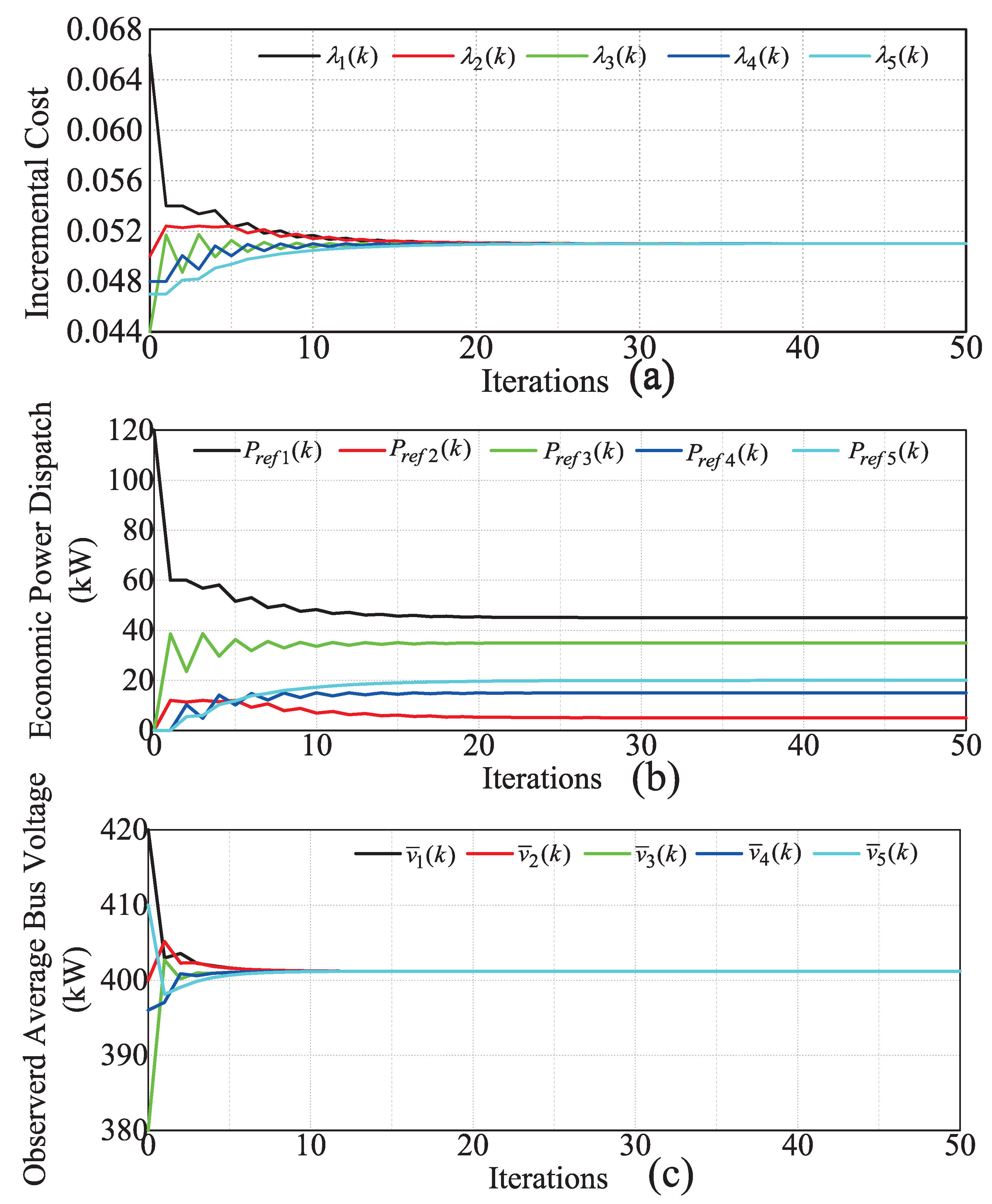
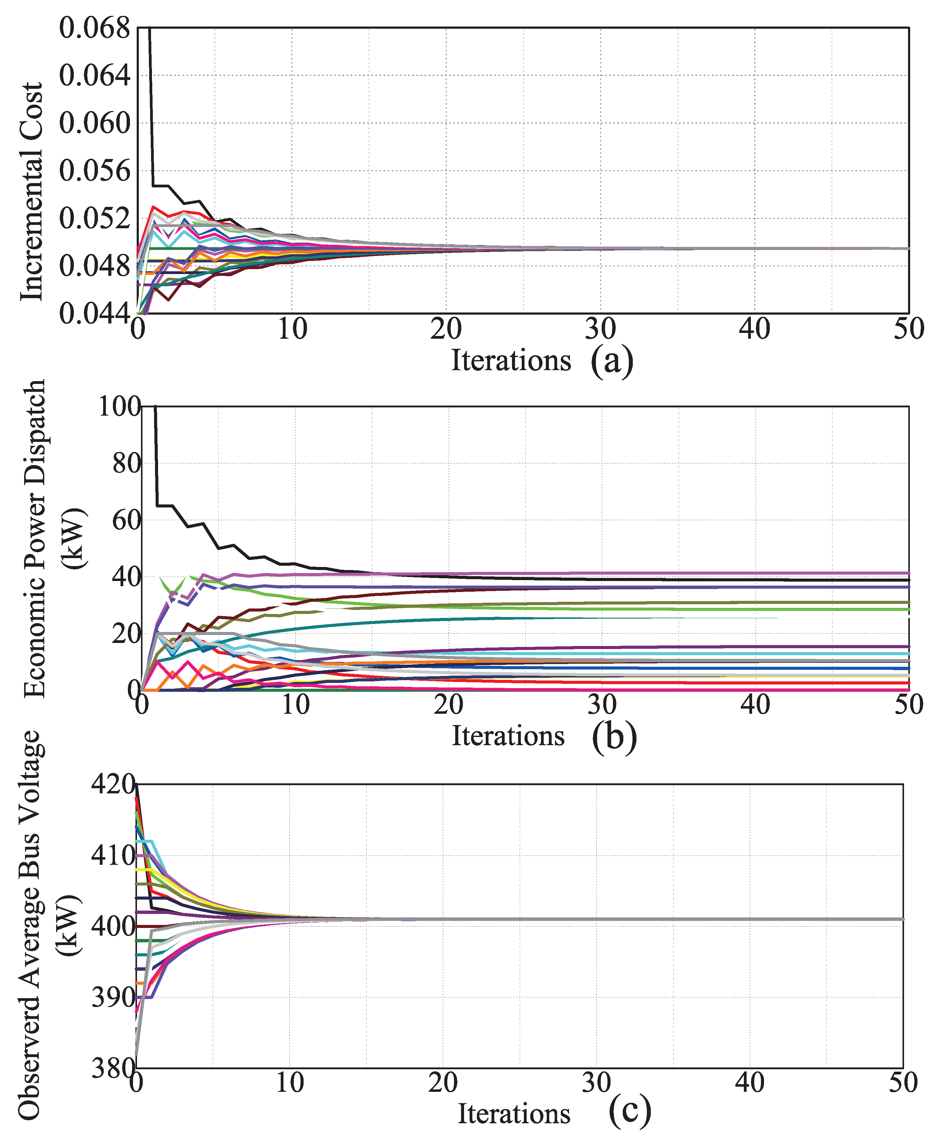
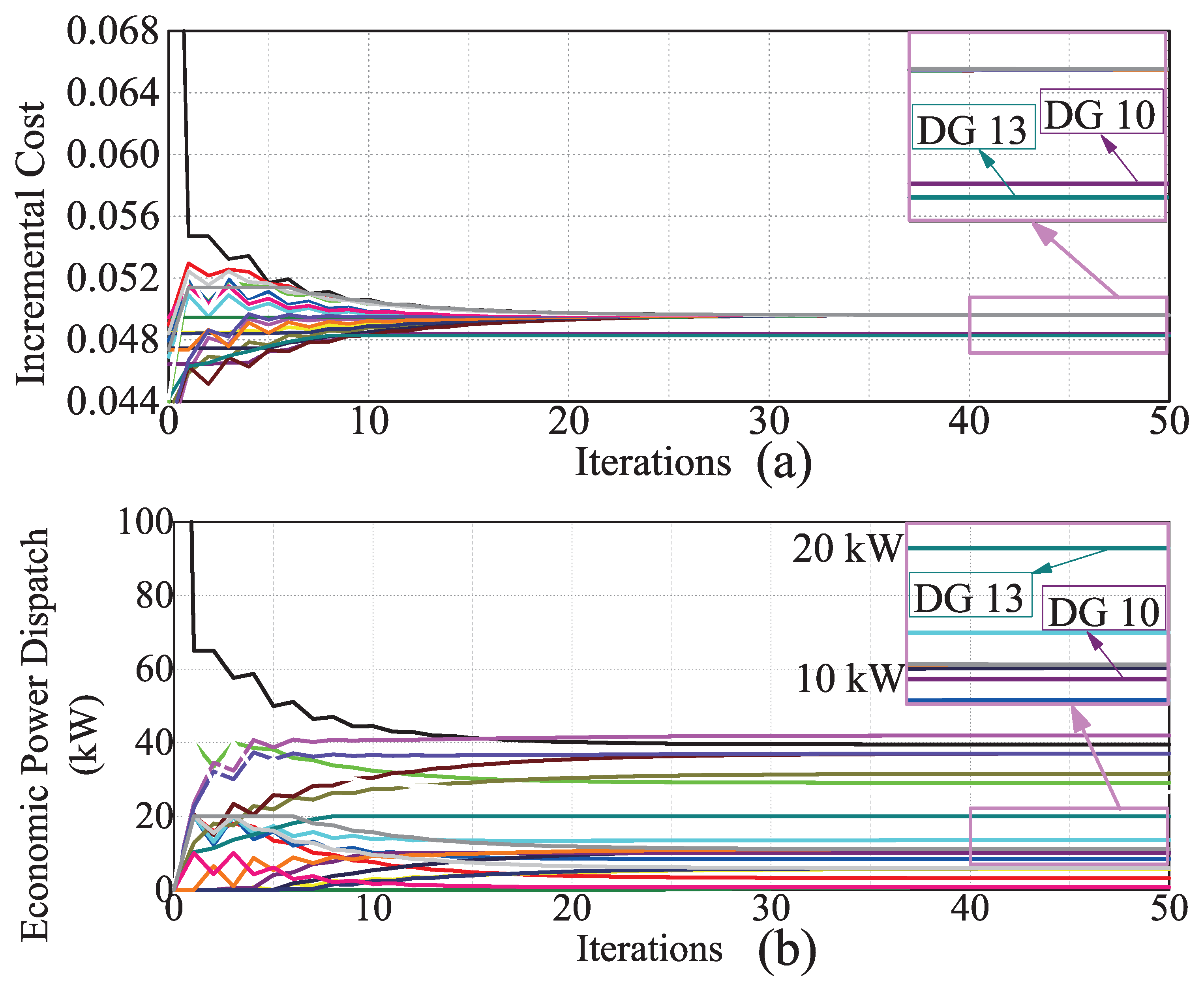
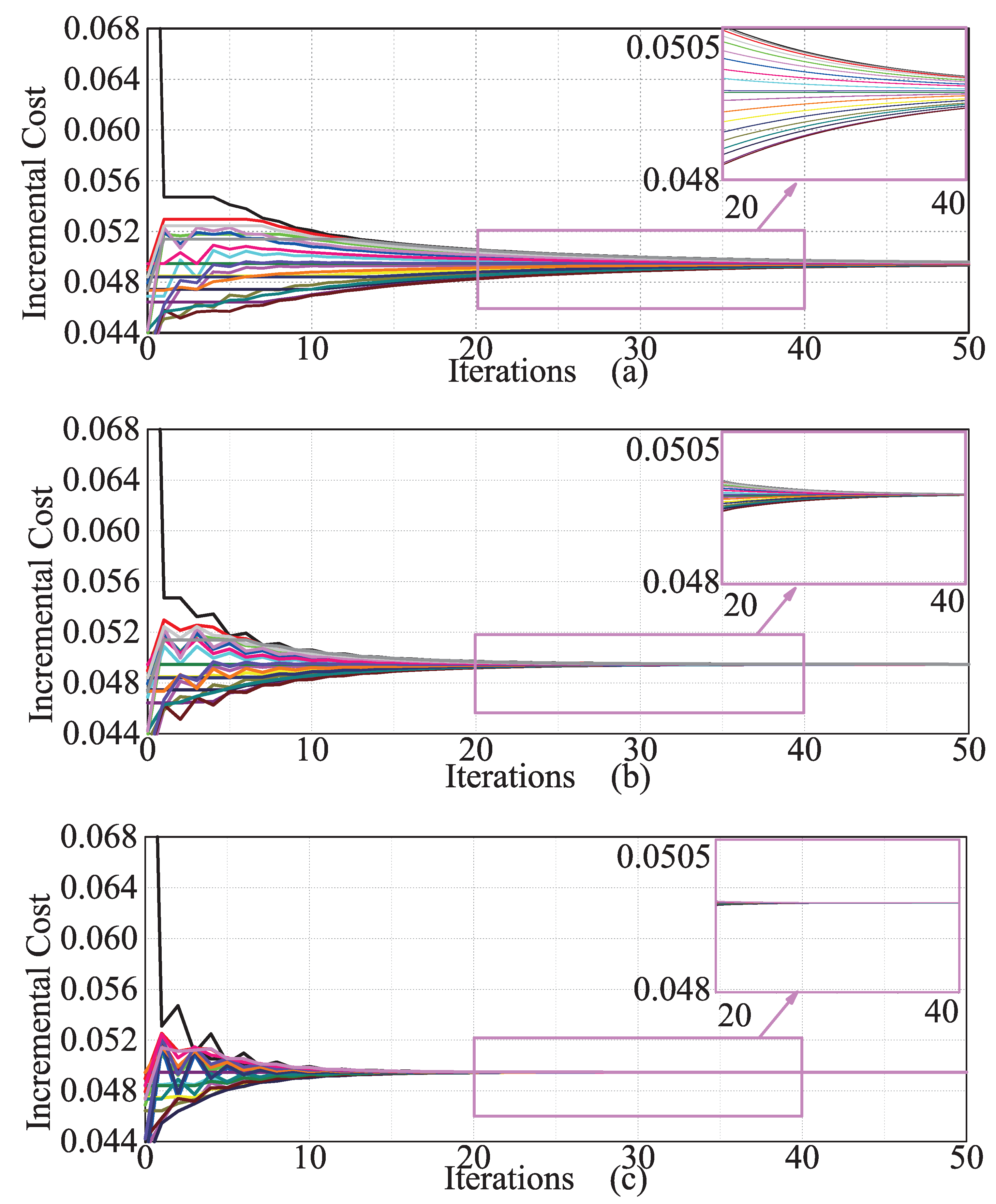
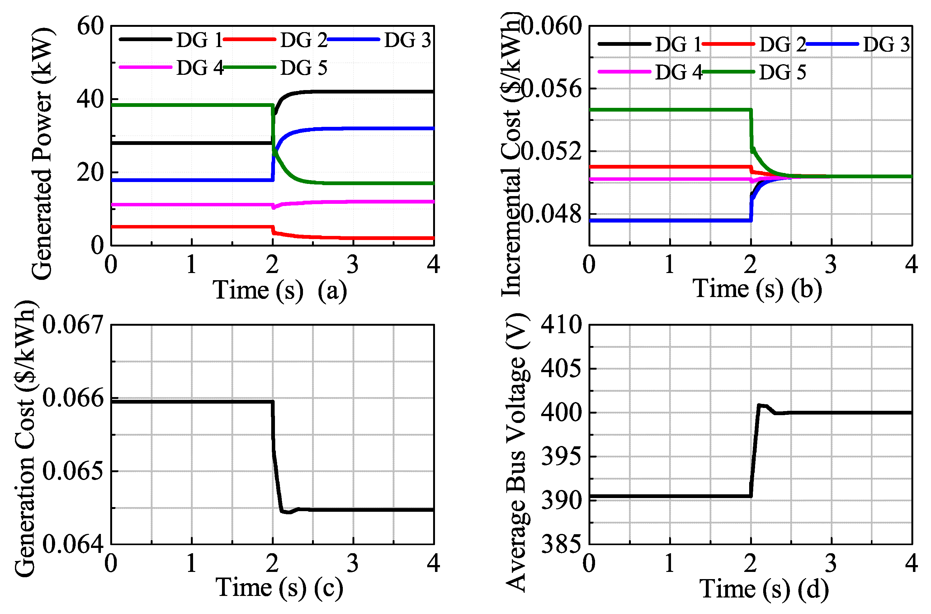
4.1. Algorithm Convergence Test

As shown in Section 3, the convergence speed of the distributed EPD and ABVO algorithms was decided by the magnitude of the second largest eigenvalue of H shown in (13) and the magnitude of the second largest eigenvalue of D shown in (17), respectively. According to this rule, the values for parameter ξ and ε were designed as ξ = 3.73 e 5 and ε = 2.41 .
The index number of adjacency matrix for the agents are shown in Table 1. Assume that the initialized states of the DC microgrid shown in Figure 5 are as follows: P r e f ( 0 ) = [ 120 , 0 , 0 , 0 , 0 ] T and v ¯ ( 0 ) = [ 420 , 400 , 380 , 396 , 410 ] T . Thus, the total load demand was 120 kW, and the average bus voltage was ( 420 + 400 + 380 + 396 + 410 ) ÷ 5 = 401.2 V. The results for the convergence test of the proposed EPD and ABVO algorithms are shown in Figure 6. According to the simulation results shown in Figure 6, the incremental costs of the DGs converged to the optimal value λ * = 0.051 , and the reference values for EPD also converged to the optimal values as follows: P r e f 1 = 45 kW, P r e f 2 = 15 kW, P r e f 3 = 35 kW, P r e f 4 = 15 kW, P r e f 5 = 20 kW. The power balance was maintained when the EPD algorithm converged, and the reference values for EPD were within the power generation constraints. As shown in Figure 6c, the values of observed average bus voltage also converged to the desired average bus voltage of 401.2 V.
The proposed EPD and ABVO algorithms were also applied to a larger DC microgrid test system with 20 DGs to investigate the scalability of the proposed algorithms with a larger system. It should be noted that the communication topology of the agents can be designed to be independent of the physical topology of the DC microgrid. Assume that the communications topology was designed such that each agent can communicate with its eight adjacent neighbors in the index numbers of i 4 , i 3 , i 2 , i 1 , i + 1 , i + 2 , i + 3 , i + 4 . The results for the convergence test of the proposed EPD and ABVO algorithms are shown in Figure 7. As shown in Figure 7, the incremental costs and the reference values for the EPD of the DGs converged to the optimal value, and the values of observed average bus voltage also converged to the desired average bus voltage of the microgrid. Furthermore, the proposed algorithms for the larger microgrid system converged within 20 iterations, which was comparable to the results shown in Figure 6. Thus, the proposed algorithms were scalable to a larger microgrid system. As shown in Figure 7, all the DGs were within their generation ranges. In order to evaluate the performance of the proposed EPD algorithm in the case that one or more DGs reached their rated power, DG 10 and DG 13 were replaced with lower rated DGs. The rated power of the renewed DG 10 and DG 13 was 10 kW and 20 kW, respectively, and the updated simulation results are shown in Figure 8. As shown in Figure 8, when DG 10 and DG 13 reached their rated power, the EPD results of DG 10 and DG 13 were 10 kW and 20 kW, respectively, and the incremental costs of DG 10 and DG 13 were lower than the other DGs, which is in accordance with the theoretical analysis shown in (9). According to the results shown in Figure 7 and Figure 8, the proposed EPD and ABVO algorithms can converge within 20 iterations even when some DGs reach their rated power for a larger microgrid system. Therefore, the convergence speed of the proposed algorithms was similar for microgrids with different sizes even when some DGs reached their rated power, demonstrating the scalability of the proposed algorithms.
In order to study the effect of the communication network topology among the agents using the proposed distributed algorithms, a convergence test of the proposed EPD algorithm for a DC microgrid with 20 DGs was conducted for three different communication topologies, i.e., each agent can communicate with its six, eight, and ten adjacent neighbors, respectively. The results of the convergence test are shown in Figure 9. As shown in Figure 9, the communication network topology had two impacts on the proposed algorithms: convergence speed and communication burden. In general, for the communication topology of an agent with more agents, the proposed algorithm would converge faster while the communication burden would increase. Therefore, the communication network among the agents should be designed by compromising between the convergence speed and the communication burden. Take the microgrid system with 20 DGs for example. For the conventional centralized method, the central controller needed to communicate with all 20 DGs in the microgrid and did all the related computation on data collected from the 20 DGs; while for the distributed control strategy, all the agents were peered, and each agent only needed to communicate with its neighbors (six, eight, or ten neighbors according to the designed communication topology) and did its local computation on data from a limited number of neighbors. Thus, each of the agent’s communication and computation burdens for a distributed method was less than that of a central controller for the centralized method.
According to the proposed EPD and ABVO algorithms shown in (13) and (16), respectively, the data to communicate with the neighboring agents included λ i , e i , and v ¯ i . In a DC microgrid system, each agent was assumed to have 10 neighbors at maximum, and the proposed EPD and ABVO algorithms can converge within 30 iterations, so the data to communicate was represented by a 32-bit number and the communication speeds between the agents assumed to be 1 Mbps. Thus, the time it takes for the proposed EPD and ABVO algorithms to converge was: 2 (bidirectional communication) × 3 (data to communicate) × 10 (neighbors) × 30 (iterations) × 32 (bit per data) ÷ 1,000,000 (1 Mbps) = 57.6 ms. Considering the impact of communication delay, the control interval for the proposed secondary-level EPD and bus voltage control should be larger than 57.6 ms. Except for the communication delay, the dynamic performance of the primary-level controllers (i.e., voltage controller and current controller) should also be considered when choosing the control interval. For tracking the reference command assigned by the proposed secondary-level controllers, the control interval should be larger than the response time of the primary-level controllers, which is generally in microseconds. Hence, considering both the factors and a proper margin requirement, the control interval was set as 0.1 s. Even if the proposed EPD and ABVO algorithm cannot converge within 0.1 s due to some extreme communication delay, the proposed secondary control only degraded to the traditional droop control. Thus, the stability of a DC microgrid system will not be affected by communication delay between the neighboring agents.

4.2. Performance Comparison with and without the Proposed Algorithm

The performance of the proposed control strategy was evaluated through a comparative study with the conventional droop control method as shown in Figure 10. The DC microgrid was initially controlled using the conventional droop control strategy. At the beginning, the average bus voltage (390 V) was less than the nominal value (400 V); the loads were shared according to the droop coefficients and line resistances, which was not an EPD. The proposed control strategy was initiated at t = 2.0 s, and consequently restored the average bus voltage of the DC microgrid to the nominal value, i.e., 400 V. As a PI controller was applied to generate the voltage correction term δ v i , 2 (as shown in Figure 3), the voltage deviation converged to zero in the steady state. Thus, the proposed algorithm had a high accuracy to eliminate voltage deviation. Meanwhile, the generation cost was decreased from 0.0659 $/kWh to 0.0645 $/kWh (with the reduction of 2.12%). A PI controller was also applied to generate the voltage correction term δ v i , 1 (as shown in Figure 3), and the incremental costs of all the DGs converged to the same value (as shown in Figure 10b), meaning that the load was optimally shared according to the generation cost of each DG. Thus, the proposed algorithm had a high accuracy in current sharing. Overall, the proposed control strategy can better achieve EPD and the bus voltage restoration at the same time.

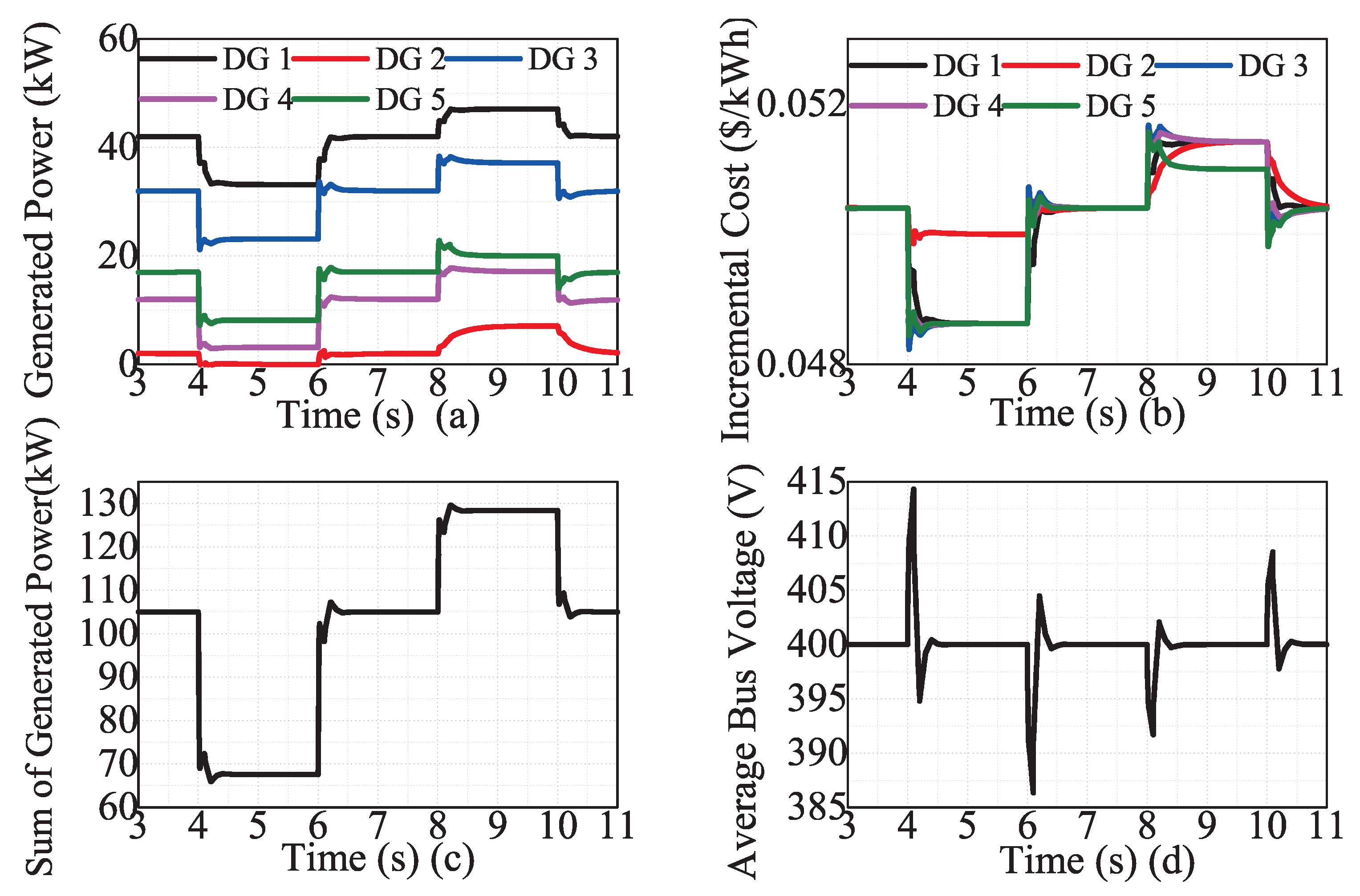
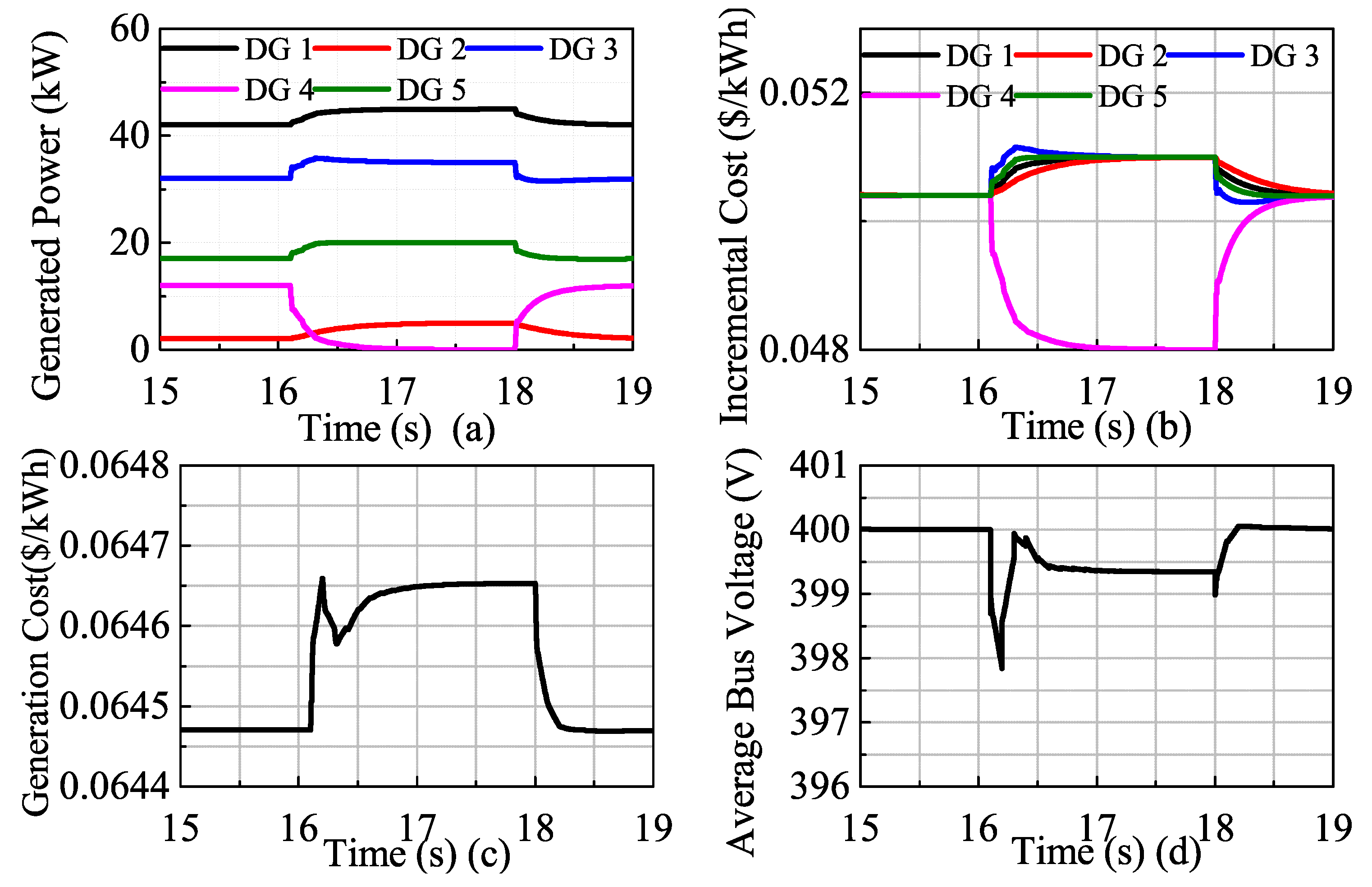
4.3. Time-Varying Load Demand Test

The performance of the proposed control strategy in the case of time-varying load demand is studied in Figure 11. At t= 4 s, the five DGs already reached the optimal states. As shown in Figure 11c, the total load demand was reduced from 105 kW to 68 kW at t = 4 s, restored to 105 kW at t = 6 s, increased to 129 kW at t = 8 s, and restored to 105 kW again at t = 10 s. Figure 11a shows that DG 2 reached its lower generation range during 4–6 s, and DG 5 reached its upper range during 8–10 s. Thus, as shown in Figure 11b, the increment cost of DG 2 was higher than the optimal value during 4–6 s, and the increment cost of DG 5 was lower than the optimal value during 8–10 s. During the other time intervals, all the DGs were within their generation ranges, and all the incremental costs converged to the optimal values. As shown in Figure 11d, the average bus voltage of the DC microgrid can also be restored to its nominal value for all the time-varying load demand conditions. Thus, the proposed control strategy was efficient even when some DGs reached their generation limits with the time-varying load demand.

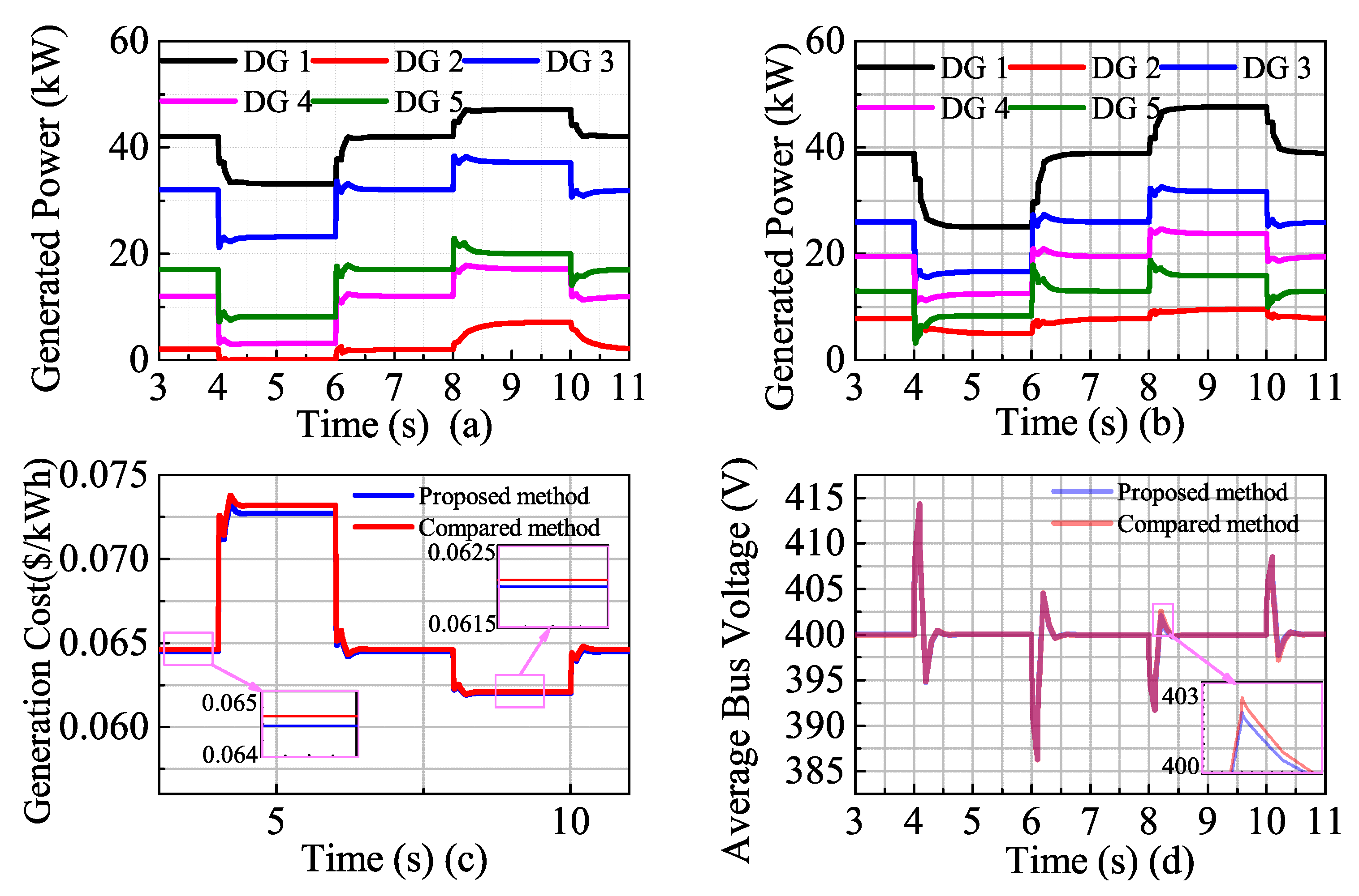
4.4. Performance Comparison with a Distributed Cooperative Control Strategy

The performance of the proposed control strategy was also compared with the distributed cooperative control strategy proposed in [4], which presented a strategy of a global voltage regulation and proportional load sharing. However, this strategy only assigned the load among participating DGs in proportion to their rated power while not considering the power generation cost of each DG. The results of the comparison studies are shown in Figure 12. From Figure 12a,b, it can be seen that the power sharing results were different between the proposed control strategy (i.e., economic load sharing) and the distributed control strategy (i.e., proportional load sharing). As shown in Figure 12c, the generation cost of the proposed control strategy was lower than that of the distributed cooperative control strategy under all load conditions as described in Section 4.3. The average bus voltage of the DC microgrid can be restored to its nominal values for both the proposed and the distributed cooperative control strategy, as shown in Figure 12d. Overall, it can be concluded that the proposed control strategy was superior to the distributed cooperative control strategy, as it can reduce the operation cost by dispatching the load in an economic way.

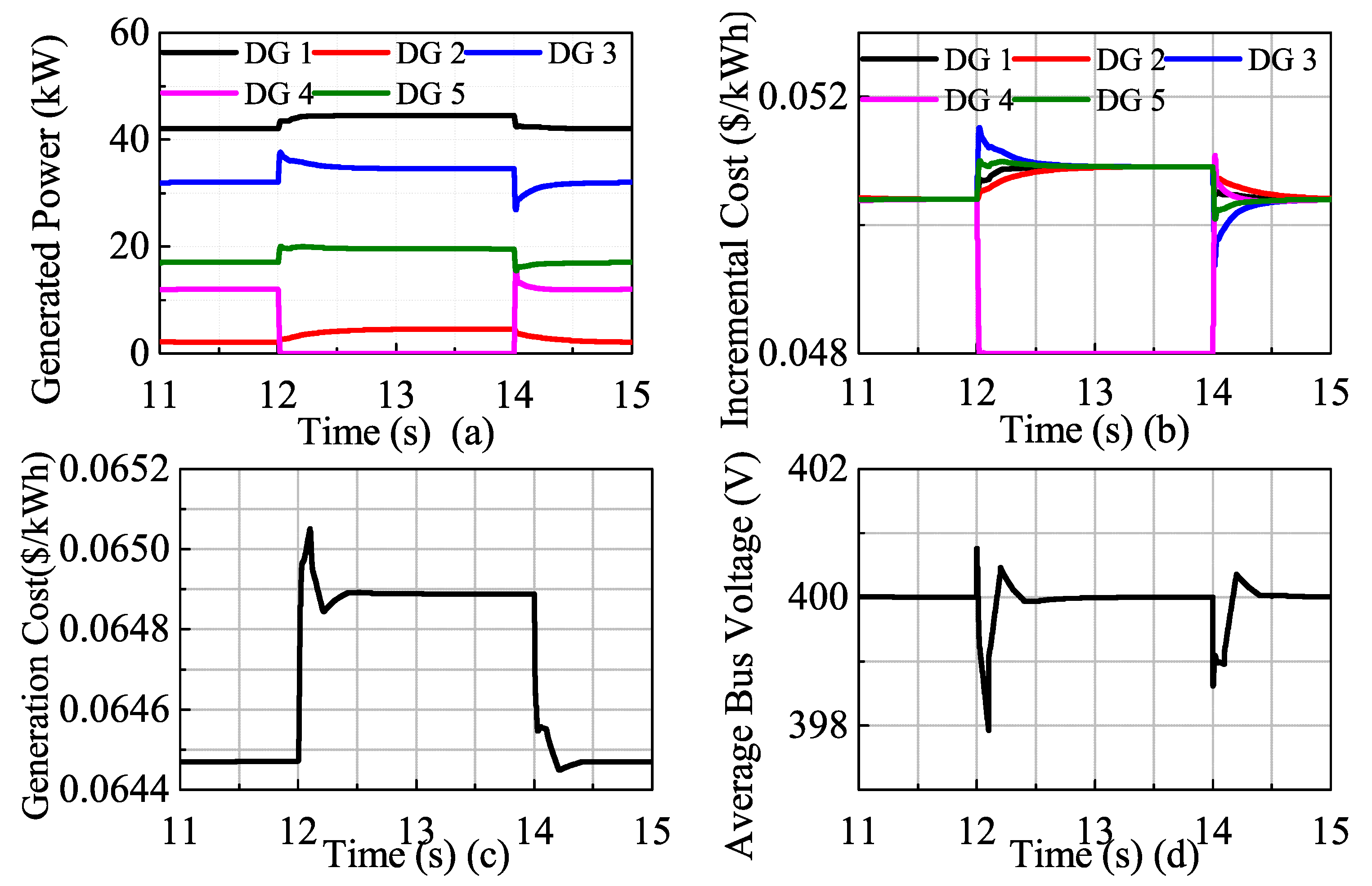
4.5. Algorithm Robustness Test

Figure 13 studies the robustness of the proposed control strategy in case a DG is turned on/turned off. At t = 11 s, the five DGs already reached the optimal states. However, DG 4 was turned off at t = 12 s and turned back on at t = 14 s. It should be noted that when a DG is turned off, its corresponding agent is still working. As shown in Figure 13, the proposed control strategy can properly update the EPD and restore the bus voltage with an admissible transient process when the working state of the DG is changed.
Figure 14 studies the robustness of the proposed control strategy in the case of agent loss. At t = 15 s, the five DGs already reached the optimal states. Agent 4 was lost at t = 16 s and recovered again at t = 18 s. It should be noted that the neighbors’ information can be updated after t = 16 s using the heartbeat packet, and the communication topology of the rest agents was still connected as it was designed to satisfy the N 1 rule, as given in Section 3.5. Assume the default reference values for EPD and voltage restoration were 0 kW and 400 V, respectively, in the case of agent loss. As shown in Figure 14, the proposed control strategy can properly update the EPD and bus voltage regulation with an admissible transient process even with an agent loss. Hence, the robustness of the proposed control strategy is verified.

5. Conclusions

In this paper, a distributed optimal bus voltage control solution for droop-controlled DC microgrids is proposed. For the proposed solution, the droop-controller on each DG was augmented with a local power controller and a local voltage controller. The local power controller compares the local output power of DG with the reference instruction generated by the proposed distributed EPD algorithm and generates a voltage correction term to share the load demand among all the participating DGs optimally. The local voltage controller uses the proposed ABVO algorithm to estimate the average bus voltage and generates a voltage correction term to provide global bus voltage regulation. Studies showed that the proposed solution can optimally share the load demand among all the participating DGs according to the power generation cost of each DG, and it can realize the global bus voltage regulation of the microgrid simultaneously. The scalability, efficiency, and robustness of the proposed control solution were verified through simulation. For future work, more improvements will be appropriate to expand the application of the proposed control strategy to more complicated EPD problems, such as consideration of the transmission line losses and the non-convex generation cost functions. The optimization of PI controllers could be another topic in our future work. Furthermore, in order to reduce the communication burden and make the proposed distributed control strategy more suitable for a real microgrid system, the event-triggered communication strategy between the distributed agents is planned for future work.

Author Contributions

All authors contributed equally.

Funding

This work was supported by the National Natural Science Foundation of China (61803343, 61876169, and 61473266), the China Postdoctoral Science Foundation (2018M630835), the Young Backbone Teachers of Henan Province (2014GGJS-004), and the Key Projects of Higher Education of Henan Province (18A470015,18A470017, and 19A120012).

Conflicts of Interest

The authors declare no conflict of interest.

References

  1. Han, R.; Meng, L.; Ferrari-Trecate, G.; Coelho, E.A.A.; Vasquez, J.C.; Guerrero, J.M. Containment and Consensus-Based Distributed Coordination Control to Achieve Bounded Voltage and Precise Reactive Power Sharing in Islanded AC Microgrids. IEEE Trans. Ind. Appl. 2017, 53, 5187–5199. [Google Scholar] [CrossRef] [Green Version]
  2. Lotfi, H.; Khodaei, A. Hybrid AC/DC microgrid planning. Energy 2017, 118, 37–46. [Google Scholar] [CrossRef]
  3. Vu, T.V.; Perkins, D.; Diaz, F.; Gonsoulin, D.; Edrington, C.S.; El-Mezyani, T. Robust adaptive droop control for DC microgrids. Electr. Power Syst. Res. 2017, 146, 95–106. [Google Scholar] [CrossRef] [Green Version]
  4. Nasirian, V.; Moayedi, S.; Davoudi, A.; Lewis, F.L. Distributed Cooperative Control of DC Microgrids. IEEE Trans. Power Electron. 2015, 30, 2288–2303. [Google Scholar] [CrossRef]
  5. Cook, M.D.; Parker, G.G.; Robinett, R.D.; Weaver, W.W. Decentralized Mode-Adaptive Guidance and Control for DC Microgrid. IEEE Trans. Power Deliv. 2017, 32, 263–271. [Google Scholar] [CrossRef]
  6. Lotfi, H.; Khodaei, A. AC Versus DC Microgrid Planning. IEEE Trans. Smart Grid 2017, 8, 296–304. [Google Scholar] [CrossRef]
  7. Balog, R.S.; Weaver, W.W.; Krein, P.T. The Load as an Energy Asset in a Distributed DC SmartGrid Architecture. IEEE Trans. Smart Grid 2012, 3, 253–260. [Google Scholar] [CrossRef]
  8. Zhang, Z.; Shi, D.; Jin, C.; Koh, L.H.; Choo, F.H.; Wang, P.; Tang, Y. Droop control of a bipolar DC microgrid for load sharing and voltage balancing. In Proceedings of the 2017 IEEE 3rd International Future Energy Electronics Conference and ECCE Asia (IFEEC 2017-ECCE Asia), Kaohsiung, Taiwan, 3–7 June 2017; pp. 795–799. [Google Scholar]
  9. Zhang, Y.; Li, Y.W. Energy Management Strategy for Supercapacitor in Droop-Controlled DC Microgrid Using Virtual Impedance. IEEE Trans. Power Electron. 2017, 32, 2704–2716. [Google Scholar] [CrossRef]
  10. Yang, N.; Paire, D.; Gao, F.; Miraoui, A. Compensation of droop control in DC microgrid with multiple distributed generators. In Cyber-Physical-Social Systems and Constructs in Electric Power Engineering; Suryanarayanan, S., Roche, R., Hansen, T., Eds.; The Institution of Engineering and Technology: London, UK, 2016; pp. 253–289. [Google Scholar]
  11. Khorsandi, A.; Ashourloo, M.; Mokhtari, H.; Iravani, R. Automatic droop control for a low voltage DC microgrid. IET Gener. Transm. Distrib. 2016, 10, 41–47. [Google Scholar] [CrossRef]
  12. Lu, X.; Guerrero, J.M.; Sun, K.; Vasquez, J.C. An Improved Droop Control Method for DC Microgrids Based on Low Bandwidth Communication With DC Bus Voltage Restoration and Enhanced Current Sharing Accuracy. IEEE Trans. Power Electron. 2014, 29, 1800–1812. [Google Scholar] [CrossRef]
  13. Dragičević, T.; Lu, X.; Vasquez, J.C.; Guerrero, J.M. DC Microgrids-Part I: A Review of Control Strategies and Stabilization Techniques. IEEE Trans. Power Electron. 2016, 31, 4876–4891. [Google Scholar] [CrossRef]
  14. Guerrero, J.M.; Vasquez, J.C.; Matas, J.; de Vicuna, L.G.; Castilla, M. Hierarchical Control of Droop-Controlled AC and DC Microgrids-A General Approach Toward Standardization. IEEE Trans. Ind. Electron. 2011, 58, 158–172. [Google Scholar] [CrossRef]
  15. Salomonsson, D.; Soder, L.; Sannino, A. An Adaptive Control System for a DC Microgrid for Data Centers. IEEE Trans. Ind. Appl. 2008, 44, 1910–1917. [Google Scholar] [CrossRef]
  16. Kakigano, H.; Miura, Y.; Ise, T. Distribution Voltage Control for DC Microgrids Using Fuzzy Control and Gain-Scheduling Technique. IEEE Trans. Power Electron. 2013, 28, 2246–2258. [Google Scholar] [CrossRef]
  17. Xu, Y.; Zhang, W.; Liu, W. Distributed Dynamic Programming-Based Approach for Economic Dispatch in Smart Grids. IEEE Trans. Ind. Inf. 2015, 11, 166–175. [Google Scholar] [CrossRef]
  18. Hu, J.; Duan, J.; Ma, H.; Chow, M.Y. Distributed Adaptive Droop Control for Optimal Power Dispatch in DC Microgrid. IEEE Trans. Ind. Electron. 2018, 65, 778–789. [Google Scholar] [CrossRef]
  19. Li, Q.; Gao, D.W.; Zhang, H.; Wu, Z.; Wang, F.Y. Consensus-Based Distributed Economic Dispatch Control Method in Power Systems. IEEE Trans. Smart Grid 2017, 10, 941–954. [Google Scholar] [CrossRef]
  20. Hu, J.; Chen, M.Z.Q.; Cao, J.; Guerrero, J.M. Coordinated Active Power Dispatch for a Microgrid via Distributed Lambda Iteration. IEEE J. Emerg. Sel. Top. Circuits Syst. 2017, 7, 250–261. [Google Scholar] [CrossRef] [Green Version]
  21. Mudumbai, R.; Dasgupta, S.; Cho, B.B. Distributed Control for Optimal Economic Dispatch of a Network of Heterogeneous Power Generators. IEEE Trans. Power Syst. 2012, 27, 1750–1760. [Google Scholar] [CrossRef]
  22. Zhang, Z.; Chow, M.Y. Convergence Analysis of the Incremental Cost Consensus Algorithm Under Different Communication Network Topologies in a Smart Grid. IEEE Trans. Power Syst. 2012, 27, 1761–1768. [Google Scholar] [CrossRef]
  23. Zhang, W.; Ma, Y.; Liu, W.; Ranade, S.J.; Luo, Y. Distributed Optimal Active Power Dispatch Under Constraints for Smart Grids. IEEE Trans. Ind. Electron. 2017, 64, 5084–5094. [Google Scholar] [CrossRef]
  24. Khorsandi, A.; Ashourloo, M.; Mokhtari, H. A Decentralized Control Method for a Low-Voltage DC Microgrid. IEEE Trans. Energy Conv. 2014, 29, 793–801. [Google Scholar] [CrossRef]
  25. Li, Z.; Zang, C.; Zeng, P.; Yu, H.; Li, H. MAS based distributed automatic generation control for cyber-physical microgrid system. IEEE/CAA J. Autom. Sin. 2016, 3, 78–89. [Google Scholar] [CrossRef]
  26. Xu, Y.; Liu, W. Novel Multiagent Based Load Restoration Algorithm for Microgrids. IEEE Trans. Smart Grid 2011, 2, 152–161. [Google Scholar] [CrossRef]
  27. Li, Z.; Zang, C.; Zeng, P.; Yu, H.; Li, H.; Li, S. Analysis of Multi-Agent-Based Adaptive Droop-Controlled AC Microgrids with PSCAD: Modeling and Simulation. J. Power Electron. 2015, 15, 455–468. [Google Scholar] [CrossRef] [Green Version]
  28. Yang, Z.; Xiang, J.; Li, Y. Distributed Consensus Based Supply-Demand Balance Algorithm for Economic Dispatch Problem in a Smart Grid With Switching Graph. IEEE Trans. Ind. Electron. 2017, 64, 1600–1610. [Google Scholar] [CrossRef]
  29. Li, L.M.; Lu, K.D.; Zeng, G.Q.; Wu, L.; Chen, M.R. A novel real-coded population-based extremal optimization algorithm with polynomial mutation: A non-parametric statistical study on continuous optimization problems. Neurocomputing 2016, 174, 577–587. [Google Scholar] [CrossRef]
  30. Yang, S.; Tan, S.; Xu, J.X. Consensus Based Approach for Economic Dispatch Problem in a Smart Grid. IEEE Trans. Power Syst. 2013, 28, 4416–4426. [Google Scholar] [CrossRef]
  31. Guo, F.; Wen, C.; Mao, J.; Chen, J.; Song, Y.D. Hierarchical Decentralized Optimization Architecture for Economic Dispatch: A New Approach for Large-Scale Power System. IEEE Trans. Ind. Inf. 2018, 14, 523–534. [Google Scholar] [CrossRef]
  32. Xing, H.; Mou, Y.; Fu, M.; Lin, Z. Distributed Bisection Method for Economic Power Dispatch in Smart Grid. IEEE Trans. Power Syst. 2015, 30, 3024–3035. [Google Scholar] [CrossRef]
  33. Zhang, W.; Liu, W.; Zang, C.; Liu, L. Multiagent System-Based Integrated Solution for Topology Identification and State Estimation. IEEE Trans. Ind. Inf. 2017, 13, 714–724. [Google Scholar] [CrossRef]
  34. Xu, Y.; Sun, H.; Gu, W.; Xu, Y.; Li, Z. Optimal Distributed Control for Secondary Frequency and Voltage Regulation in an Islanded Microgrid. IEEE Trans. Ind. Inf. 2019, 15, 225–235. [Google Scholar] [CrossRef]
  35. Meng, W.; Wang, X.; Liu, S. Distributed Load Sharing of an Inverter-Based Microgrid With Reduced Communication. IEEE Trans. Smart Grid 2018, 9, 1354–1364. [Google Scholar] [CrossRef]
  36. Xu, Y. Robust Finite-Time Control for Autonomous Operation of an Inverter-Based Microgrid. IEEE Trans. Ind. Inf. 2017, 13, 2717–2725. [Google Scholar] [CrossRef]
  37. Savaghebi, M.; Jalilian, A.; Vasquez, J.C.; Guerrero, J.M. Autonomous Voltage Unbalance Compensation in an Islanded Droop-Controlled Microgrid. IEEE Trans. Ind. Electron. 2013, 60, 1390–1402. [Google Scholar] [CrossRef] [Green Version]
  38. He, J.; Li, Y.W.; Bosnjak, D.; Harris, B. Investigation and Active Damping of Multiple Resonances in a Parallel-Inverter-Based Microgrid. IEEE Trans. Power Electron. 2013, 28, 234–246. [Google Scholar] [CrossRef]
  39. Jayawarna, N.; Barnes, M. Study Of A Microgrid With Vehicle-To-Grid Sources During Network Contingencies. Intell. Autom. Soft Comput. 2010, 16, 289–302. [Google Scholar] [CrossRef]
  40. Lu, K.; Zhou, W.; Zeng, G.; Zheng, Y. Constrained population extremal optimization-based robust load frequency control of multi-area interconnected power system. Int. J. Electr. Power Energy Syst. 2019, 105, 249–271. [Google Scholar] [CrossRef]
  41. Lu, K.; Zhou, W.; Zeng, G.; Du, W. Design of PID controller based on a self-adaptive state-space predictive functional control using extremal optimization method. J. Frankl. Inst. Eng. Appl. Math. 2018, 355, 2197–2220. [Google Scholar] [CrossRef]
  42. Zeng, G.Q.; Chen, J.; Dai, Y.X.; Li, L.M.; Zheng, C.W.; Chen, M.R. Design of fractional order PID controller for automatic regulator voltage system based on multi-objective extremal optimization. Neurocomputing 2015, 160, 173–184. [Google Scholar] [CrossRef]
  43. Li, Z.; Zang, C.; Zeng, P.; Yu, H.; Li, S.; Bian, J. Control of a Grid-Forming Inverter Based on Sliding-Mode and Mixed H2/H Control. IEEE Trans. Ind. Electron. 2017, 64, 3862–3872. [Google Scholar] [CrossRef]
  44. Fu, X.; Li, S. Control of Single-Phase Grid-Connected Converters WithLCLFilters Using Recurrent Neural Network and Conventional Control Methods. IEEE Trans. Power Electron. 2016, 31, 5354–5364. [Google Scholar] [CrossRef]
Figure 1. Proposed control diagram of converter-interfaced DGs in a DC microgrid.
Energies 12 01400 g001
Figure 2. Agent-based distributed control architecture for a DC microgrid.
Energies 12 01400 g002
Figure 3. Proposed distributed optimal bus voltage control for droop-controlled DC microgrids. EPD, economic power dispatch; ABVO, average bus voltage observation.
Energies 12 01400 g003
Figure 4. Implementation of the proposed control algorithms.
Energies 12 01400 g004
Figure 5. The system configuration of the DC microgrid test system.
Energies 12 01400 g005
Figure 6. Convergence test of the EPD and ABVO algorithms for a DC microgrid with 5 DGs. (a) Incremental cost of the DGs in each iteration; (b) EPD of the DGs in each iteration; (c) observed average bus voltage of the DGs in each iteration.
Energies 12 01400 g006
Figure 7. Convergence test of the EPD and ABVO algorithms for a larger DC microgrid with 20 DGs. (a) Incremental cost of the DGs in each iteration; (b) EPD of the DGs in each iteration; (c) observed average bus voltage of the DGs in each iteration.
Energies 12 01400 g007
Figure 8. Convergence test of the EPD and ABVO algorithms for a larger DC microgrid with 20 DGs when two DGs reached their rated power. (a) Incremental cost of the DGs in each iteration; (b) EPD of the DGs in each iteration.
Energies 12 01400 g008
Figure 9. Convergence test of the EPD algorithm for a DC microgrid with 20 DGs when the communication network among agents is designed with different topologies. (a) Each agent communicates with its six adjacent neighbors; (b) each agent communicates with its eight adjacent neighbors; (c) each agent communicates with its ten adjacent neighbors.
Energies 12 01400 g009
Figure 10. Comparative studies of a DC microgrid before and after the proposed control strategy was applied. (a) Generated power of each DG. (b) Incremental cost of each DG. (c) Total generation cost of all the DGs. (d) Average bus voltage of the microgrid.
Energies 12 01400 g010
Figure 11. Performance of the proposed control strategy with time-varying load demand. (a) Generated power of each DG. (b) Incremental cost of each DG. (c) Total generated power of all the DGs. (d) Average bus voltage of the microgrid.
Energies 12 01400 g011
Figure 12. Comparative studies between the proposed control strategy and distributed cooperative control. (a) Generated power of each DG with the proposed control strategy. (b) Generated power of each DG with the conventional distributed cooperative control. (c) Total generation cost of all the DGs. (d) Average bus voltage of the microgrid.
Energies 12 01400 g012
Figure 13. Performance of the proposed control strategy with a DG turned off. (a) Generated power of each DG. (b) Incremental cost of each DG. (c) Total generation cost of all the DGs. (d) Average bus voltage of the microgrid.
Energies 12 01400 g013
Figure 14. Performance of the proposed control strategy with an agent loss. (a) Generated power of each DG. (b) Incremental cost of each DG. (c) Total generation cost of all the DGs. (d) Average bus voltage of the microgrid.
Energies 12 01400 g014
Table 1. Parameters of the DGs.
DG and Agent
Index
Neighboring
Agents
a i
$ / kW 2 h
b i
$ / kWh
c i
$ / h
m i
V/A
Range
kW
12,30.00010.0420.250.1533[0, 60]
21,40.00010.050.420.7667[0, 12]
31,4,50.00010.0440.350.2410[0, 40]
42,3,50.00010.0480.450.3213[0, 30]
53,40.00010.0470.330.0640[0, 20]

