Article

The Impact of Fuel Type on the Output Parameters of a New Biofuel Burner

1
Department of Organization and Production Engineering, Warsaw University of Life Sciences, Nowoursynowska Street 164, 02-787 Warsaw, Poland
2
Department of Production Management, Bialystok University of Technology, Wiejska Street 45A, 15-351 Bialystok, Poland
3
Faculty of Mechanical Engineering, Institute of Technological Information Systems, Lublin University of Technology, Nadbystrzycka 38 D, 20-618 Lublin, Poland
*
Authors to whom correspondence should be addressed.
Energies 2019, 12(7), 1383; https://doi.org/10.3390/en12071383
Submission received: 26 February 2019 / Revised: 8 April 2019 / Accepted: 8 April 2019 / Published: 10 April 2019
(This article belongs to the Special Issue Cleaner Combustion)

Abstract

:
Intensified action aimed at reducing CO2 emissions and striving for energy self-sufficiency of both business entities and individual consumers are forcing the sustainable development of environmentally friendly and renewable energy sources. The development of an appropriate class of equipment and production technology is not without significance in this process. On the basis of a proven design for a combustion burner for ecological fuels, a new biofuel burner, also dedicated to prosumers’ energetics, was built. The aim of the study was to determine the effect of the type of biofuel on a burner’s output parameters, especially gaseous emissions, during the combustion of four types of fuels, including three types of biomass. The combustion temperature was measured for lignite, wood pellets, straw pellets, and sunflower pellets. An analysis of exhaust gas composition was performed for lignite and wood pellets. The results of exhaust emissions and combustion temperatures were compared with the burners currently in use. The use of a new burner might contribute to cleaner combustion and reducing the emissions of some gaseous components.

1. Introduction

Declining reserves of fossil fuels [1,2] and a marked increase in their prices combined with the emission of dangerous and harmful carbon dioxide into the atmosphere are just some of the factors that cause interest in renewable energy sources [3,4]. In addition to energy from water, wind, or solar radiation, biomass is the most commonly used source of renewable fuel [5,6]. Its importance as a clean, inexpensive, and renewable source of energy is clear, particularly when it is produced from agricultural and forestry remains [7,8].
The moisture content of biomass has a significant impact on the content of flammable parts in ash and slag [9,10], the combustion efficiency [11,12] and the place of ignition [13,14]. A high content of water vapor in the flue gas reduces the temperature in the furnace, thus reducing the combustion temperature [15,16]. Delivering to the burner a fuel with proper grinding and humidity [17,18], maintaining the appropriate level of air gradation, and even guaranteeing optimal temperature and burning time [19,20] are the parameters guaranteeing correct ignition, complete and total combustion, as well as low emission of pollutants in the exhaust gases [21,22].
Biomass resources can be a fuel for a number of large steam power plants as well as for small production plants [23,24]. Combustion can be carried out using devices and installations designed exclusively for biomass, but also as an auxiliary fuel for coal combustion [25,26]. As in the case of coal, biomass is burned in boilers with a dust or grate furnace [27,28].
Knowledge of the parameters affecting the combustion process positively and unfavorably allows for improvement and proper selection of fuel for a given type of furnace chamber [29,30].
Also, the design of burners for various fuels has become a research priority, searching for optimal flame structure and temperature distribution to assure the most effective combustion [31,32].
Similar strategies are involved in the construction of burners for biofuel combustion. Biomass burning boilers should contain two separate spaces: one for degassing and one for burning a complete part of volatile fuel products [33,34].
The ecological fuel burner consists of a furnace assembly, air preparation and supply unit, fuel tank connected by a screw conveyor with a combustion chamber, and ash gutter with auger assembly of ash extractor (the invention is protected by Polish Patent No. 221180—Boiler for ecological fuels, especially brown coal). The combustion chamber is cylindrical and has left-handed or clockwise openings through which the air is forced through the air preparation and supply unit. In addition, the combustion chamber has, in the upper part, a hot exhaust outlet connected to a heat exchanger. Outside of the combustion chamber there is a hopper, which is connected with a combustion chamber using a screw conveyor. In addition, in the lower part of the combustion chamber there is an ash gutter with blast nozzles, and below the ash gutter there is a screw conveyor of ash extraction. The combustion chamber is partially surrounded by a water cooling unit with heat recovery. The main advantage of the burner is the possibility of using ecological fuel (such as wood chips, briquettes from sawdust, and other fuels), which is rarely used due to the high water content. The pre-drying and drying system that takes place during the transport of fuel to the combustion chamber increases the energy value of the fuel and the vortex motion in the chamber allows for effective combustion. Another advantage is the high combustion efficiency of 94% (in the case of brown coal).
The aim of the study was to determine the effect of the type of biofuel on a burner’s output parameters, especially gaseous emissions, during the combustion of four types of fuels, including three types of biomass. The new biofuel burner is compared with the old burner for use with ecological fuels. The combustion of lignite, wood pellet, straw pellets, and sunflower pellets was analyzed, mainly having in mind the flame behavior, temperature distribution, and gaseous emissions.

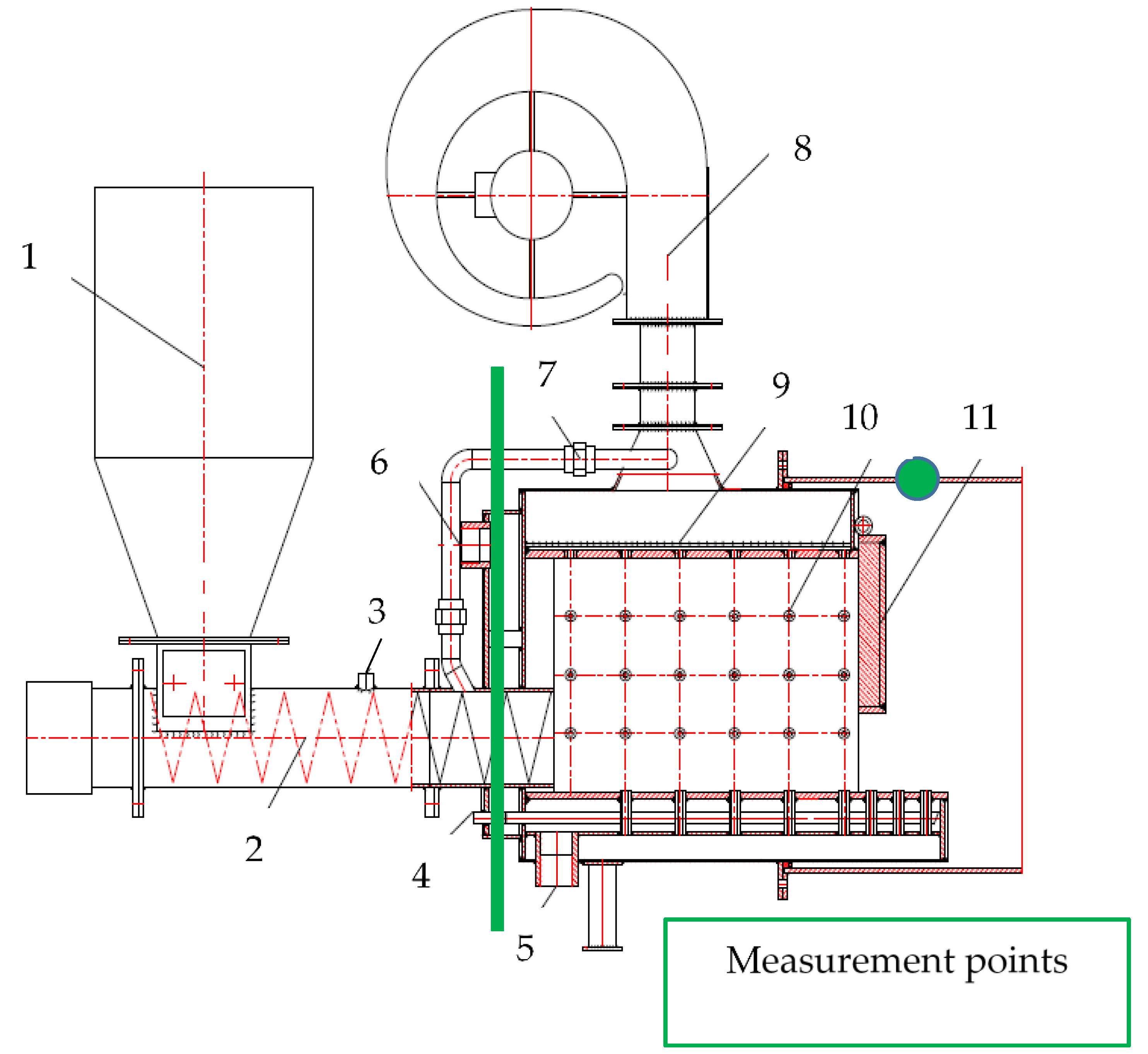
2. The Design of a New Biofuel Burner

The construction of a new biofuel burner was created on the basis of the invention described above. The idea for a new version of the burner called a new biofuel burner was to reduce the burner’s dimensions while maintaining the thermal efficiency of the device.
Differences and similarities between the burner for ecological fuels and the new biofuel burner are summarized in Table 1.
The new biofuel burner is smaller, simpler in design, and contains fewer components—which reduces the risk of device failure. What distinguishes it from the previous version is a built-in fuel degassing system and ash cooling system protecting against slagging (sinking).
The new biofuel burner is equipped with a fuel drying system that uses warm air from the combustion process. Since the drying is achieved by means of the hot air being the byproduct of a system, it increases the thermodynamic effectiveness of the device. A fan that causes a swirl movement of gases is placed in the upper part of the combustion chamber, where volatile parts of the fuel appear. Similarly to the first solution, the new biofuel burner is equipped with a charging hopper, a screw feeder embedded in the pipe, a cylindrical combustion chamber with a water jacket, and an automatic ash extraction system. The schematic picture of the burner is shown in Figure 1. A biofuel burner, due to its dimensions, can be placed on the trolley to create a mobile system for the production of process steam, in the event of the failure of a regular source of steam in large industrial plants. Also, the small dimensions of the new burner extend the application towards a wider range of consumers with smaller heating power needs.
The fuel can be supplied from the built-in charging hopper or from the storage room adjacent to the boiler room. The fuel is transported by means of a gearmotor (a device consisting of an electric motor and a gear reducer, constituting the drive of the auger, which is connected by means of a collar with a keyway). During transport, the fuel is heated and dried through the air pressed through the pipe into the screw housing. The fuel particles heat up and give off excess water, and further heating triggers the pyrolysis process. Then the fuel is directed to a combustion chamber made of heat-resistant sheet and undergo degassing. After degassing, the volatile parts of the fuel in the vortex motion burn off completely, and the solid parts are pushed into the combustion chamber of the boiler. The burner combustion pressure is approximately 0.024 MPa (0.24 bar). The flue gas under this pressure is directed to the steam generator or steam boiler, heating the water and evaporating the steam. The burner operation is controlled by means of a control cabinet, thanks to which it is possible to control the fuel supply and the amount of air. To facilitate the operation of the burner, a controller system based on the increase of temperature and pressure was used, which enables the system to select the ratio of fuel and air, thereby ensuring the ideal composition of the combustible mixture.
Most of the biomass burning technologies currently used in burners use air vortex movement [35,36]. These constructions have a rotating combustion chamber and blades that cause a swirl of air in the combustion chamber [37,38,39]. A biofuel burner has a cylindrical, fixed combustion chamber, and the air vortex is forced by the fan at 1000 Pa pressure. A detailed comparison of the biofuel with other solutions available on the Polish market is presented in Table 2.

3. Materials and Methods

3.1. Materials

The behavior of the following fuels was compared for both the old burner and the new biofuel burner. The fuels use brown coal (lignite), wood pellets, straw pellets, and sunflower seed pellets. The pine pellet, containing an admixture of deciduous trees, was manufactured by King Pellet. The straw pellets made of cereal straw was produced by Polenergia. The physicochemical properties of all fuels used are summarized in Table 3, based on the manufacturer’s data.

3.2. Methodology

The subject of the research was a comparison of the combustion of several fuels in a burner for ecological fuels and the construction of a new burner for biofuels (biofuel burner).
The following measurements were made on the same types of fuels for both devices:

3.2.1. Humidity of the Fuel

To determine the humidity of the pellets, a pellet moisture meter Tanel PEL-20 (produced by MERA Poland) with a measuring range 10–20% and accuracy of 0.1% was used.

3.2.2. Flue Gas Analysis

The following measurements were made on the same type of fuel for both devices. For the purpose of determining the composition of the flue gas, an exhaust gas analyzer TESTO 320 basic, with a measuring range of 0–4000 ppm and accuracy of 1 ppm was used.

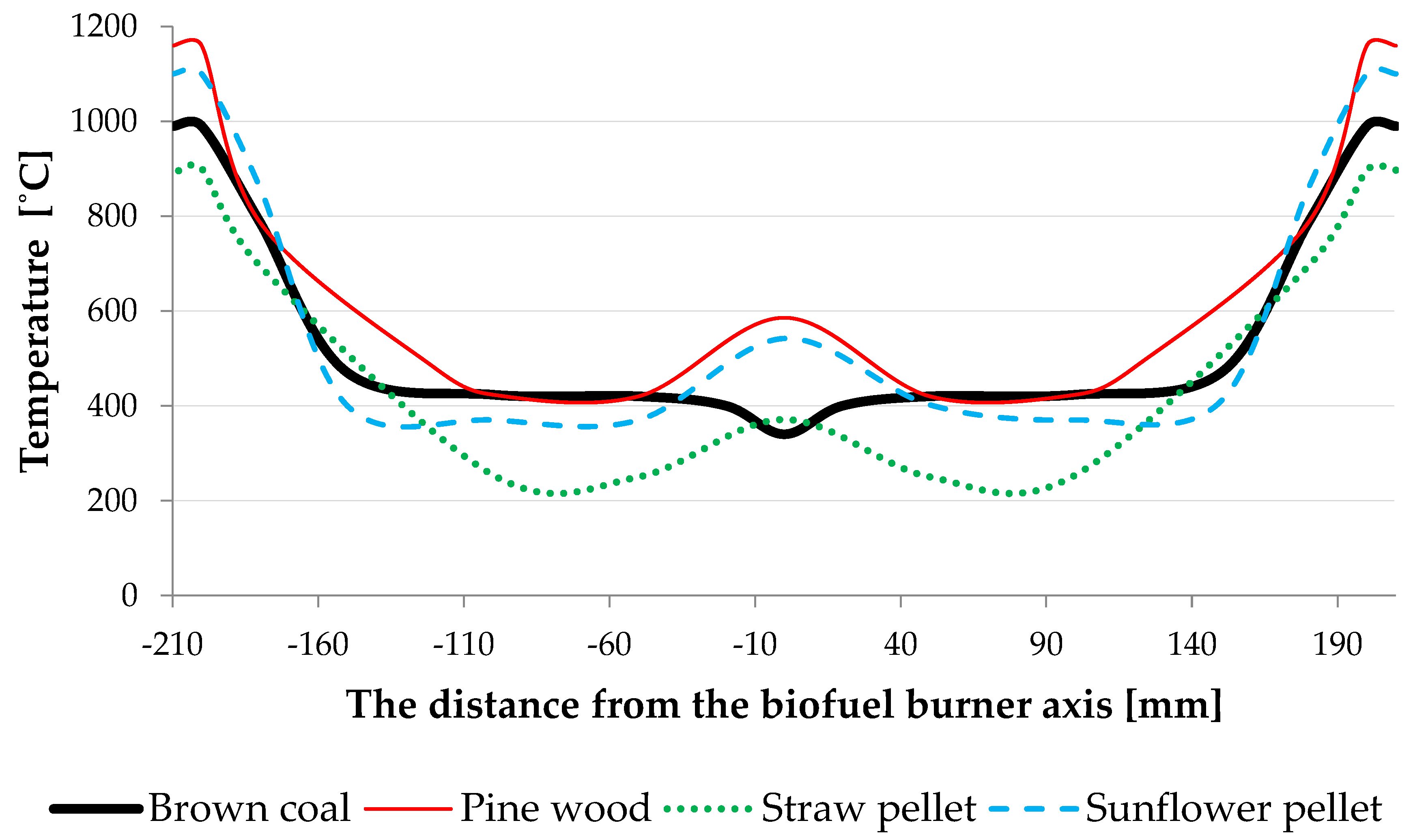
3.2.3. Temperature Measurements

The apparatus used to measure the temperature was a thermovision camera and a pyrometer. The first temperature measurement was made one hour after lighting, the second after one and a half hours, and the third after an hour and 45 min. The accuracy and range of the measuring devices used are given in Table 4.

4. Results and Discussion

Temperature measurements were carried out at the following stages and locations in the burner:
  • drying of fuel,
  • fuel combustion,
  • secondary air,
  • inside the combustion chamber 100 mm from the axis of the burner,
  • inside the combustion chamber 180 mm from the axis of the burner,
  • flue gas outlet to the boiler.
The points of measurements are shown in Figure 1.
The temperature distribution profile across the burner was also determined. A graph showing the temperature distribution in relation to the diameter of the biofuel burner is presented in Figure 2.
It is seen that the temperature inside the combustion chamber is distributed symmetrically. The highest temperatures inside the combustion chamber were noted at the edges of the walls, then, approaching the axis of the screw feeder, they decreased; whereas at the same fuel inlet from the feeder to the chamber a temperature rise was again noted. The laboratory combustion curve from the literature coincides with the results of the measurements carried out on the burner, except for lignite (Figure 2). The results of the measurements of the fuels are presented in Table 5.

4.1. The Exhaust Gas Analysis

To determine the emission level of the burner (in the case of brown coal) and check whether it meets the emission standards regarding the content of impurities in the flue, the gas analysis was compared to the requirements of PN-EN 303-5/2012. The results are summarized in Table 6.

4.2. Summary of Biofuel Burner Characteristics

To determine the total power of the steam generator equipped with the new biofuel burner, it was necessary to calculate the power of the steam boiler, the power of the cooling system of the burner, and the chemical energy of the fuel burned.
In the case of characteristic values of exhaust gases, calculations were made only for lignite, because of all the fuels used for testing, only in the case of brown coal are the fuel composition reports generally available. The composition of lignite is presented in Table 3. The results of all calculations are presented in Table 7.
It can be concluded from Table 7 that, e.g., the ash content in flue gas is as low as 0.01% (mass), which appears rather low as compared with the data for classical burners [41,42].
The latter source [42] also reports higher CO2 content in exhaust gas (11.6%, while our biofuel-burner has 9.8%). It can be concluded, therefore, that higher air excess is assured by the controlling unit, which also results in better combustion.
The brown coal combustion temperature was 1000 °C. Lignite is one of the fuels containing the highest water concentration. When air is injected into the tube with an embedded worm screw, the fuel starts to evaporate and the drying temperature is reduced from 500 °C to 340 °C. At the outlet from the burner to the boiler, the flue gas reached a temperature of about 1100 °C. Ash and moisture reduce the heating value of lignite and, consequently, the output parameters of its combustion.
During the combustion of wood pellets made of sawdust from pine wood, the temperature was read at 1160 °C; at the inlet of the pellet to the furnace the temperature reached 585 °C, and the secondary air temperature was 612 °C. In terms of temperature and emission performance, it is the recommended fuel for this type of equipment.
Straw as biomass for combustion is an attractive fuel due to the low price and high availability. The main problem when operating straw-fired machines is the high silicon content. During harvesting and storage, a large amount of sand accumulates, which during combustion leads to sintering, resulting in a shortening of the life of the burner. In addition, ash from incombustible straw substances has a low melting point of about 95–105 °C, which also results in slagging of the furnace. The combustion temperature compared to other fuels is lower, at 993 °C, and the drying temperature during transport is 371 °C. It can be concluded, therefore, that straw is not an appropriate fuel for the constructed burner.
Pellets from the sunflower husks used for measurements were made with an admixture of sawdust from deciduous trees and oak wood, which increases the calorific value and reduces the susceptibility to sintering. The ash obtained from combustion can be used as an organic fertilizer. The fuel inlet temperature for the combustion chamber is 541 °C, 1100 °C combustion, and the exhaust outlet 1211 °C.
Calculations of exhaust emissions were made using lignite data as it is the only fuel with an elementary chemical composition report. As a result of combustion in the biofuel, there is emission of moist exhausts, i.e., those in which there is water in the form of water vapor. Gases like N2, O2, and H2O are neutral for the environment because they are present in the air. The CO2 emissions were determined to be 103.62 kg/h, while those of sulfur dioxide (SO2) were 1.62 kg/h.
The main design strategy of the new biomass burner design was to reduce its size while maintaining combustion efficiency. Analyzing the measurements made and the temperature values read from the burner controller for ecological fuels (Table 8), it can be concluded that the assumption has been met.
The correctness of the results of the conducted tests was also verified by comparison to the values of fuel combustion in a swirl burner presented in [43], considered as a reference.
The fuel whose combustion guarantees very good burning parameters and favorable economic and ecological estimates is fine brown coal [44,45]. The calorific value of granulate 0–20 mm is 9–15 MJ/kg, and the combustion temperature is around 1100 °C [46]. The ash content is only 4–9%, and the sulfur content is 0.42 ± 0.90% (the sulfur content in bituminous coal is 5–12% and is a factor causing corrosion and shortening the life of the burner and the boiler) [47,48]. For comparison, the calorific value of lignite pea coal (granulation: 20–30 mm) is 10–15 MJ, and that of brown coal (granulation: 40–250 mm) is 10–20 MJ. High-calorific brown coal fine imported from the Czech Republic is also available on the Polish market (granulation 0–10 mm, average calorific value 16.9 kJ/kg, average ash content 13.1%, average sulfur content 0.84%, average humidity 29.7%) [49].
The results of the present investigation show that this classic fuel can be replaced by several types of biofuels when an appropriate burner design is used. For comparison, wood pellets and briquettes are burned at a temperature of about 1250 °C, with a calorific value about 19 MJ/kg. Wood chips and energetic willow have a lower thermal efficiency due to the increased humidity. Their combustion temperature is within the range 900–1000 °C. Cereals and straw briquettes reach temperatures up to 1100 °C with a calorific value of 8–14 MJ/kg. Pellets from sunflower husks reach combustion temperature at 1200 °C, and their calorific value is 17–19 MJ/kg [50]. Ash as a secondary product can be used for soil fertilization in agriculture and horticulture [51,52].

5. Conclusions

In the above study, the object of the research was the comparison of the performance of several fuels in a burner for ecological fuels and a new biofuel burner. Based on the conducted analyses, it can be stated that:
  • The fuel that achieved the best burning parameters was wood pellets made of pine. Its calorific value is 19.4 MJ/kg and the combustion temperature was 1235 °C.
  • In the case of lignite, the average exhaust gas temperature was 1089 °C; for straw pellets it was 993 °C, and for sunflower pellets 1212 °C.
  • The measurements made with the exhaust gas analyzer show that the proposed burner solution meets the emission standards regarding the content of impurities in the exhaust.
  • The laboratory combustion curve from the literature coincides with the results of the measurements carried out.
  • It should be noted that especially emission of ash from a modernized burner is lower than from a traditional one.
Due to the wide application possibilities of the proposed biofuel burner construction, its installation in industrial plants can be an effective pro-ecological solution through cleaner combustion and the reduction of harmful emissions.
It should be emphasized that the problem of air pollution in heating not only applies to the fuel used; the technique and appropriate combustion technology are also important. The wider introduction of such burners, even on the local scale, will ultimately aid the global struggle for a cleaner atmosphere.

Author Contributions

Conceptualization, K.T. and J.W.; Methodology, O.O. and A.W.; Validation, A.Ś. and K.T.; Investigation, O.O. and A.W.; Writing—Original Draft Preparation, A.Ś. and J.W.; Funding Acquisition, A.Ś.

Funding

The authors wish to express gratitude to Lublin University of Technology for financial support given to the present publication (Antoni Świć). The research was carried out under financial support obtained from the research subsidy of the Faculty of Engineering Management (WIZ) of Bialystok University of Technology (Olga Orynycz, Andrzej Wasiak).

Acknowledgments

The authors wish to express their deep gratitude to Lublin University of Technology for the financial support given to the present publication (A.Ś.). The research was carried out with financial support obtained from the research subsidy of the Faculty of Engineering Management (WIZ) of Bialystok University of Technology (O.O., A.W.).

Conflicts of Interest

The authors declare no conflict of interest. The funders had no role in the design of the study; in the collection, analyses, or interpretation of data; in the writing of the manuscript, and in the decision to publish the results.

References

  1. Handayani, K.; Krozer, Y.; Filatova, T. From fossil fuels to renewables: An analysis of long-term scenarios considering technological learning. Energy Policy 2019, 127, 134–146. [Google Scholar] [CrossRef]
  2. Martins, F.; Felgueiras, C.; Smitková, M. Fossil fuel energy consumption in European countries. Energy Procedia 2018, 153, 107–111. [Google Scholar] [CrossRef]
  3. Mączyńska, J.; Krzywonos, M.; Kupczyk, A.; Tucki, K.; Sikora, M.; Pińkowska, H.; Bączyk, A.; Wielewska, I. Production and use of biofuels for transport in Poland and Brazil—The case of bioethanol. Fuel 2019, 241, 989–996. [Google Scholar] [CrossRef]
  4. Gökgöz, F.; Güvercin, M.T. Energy security and renewable energy efficiency in EU. Renew. Sustain. Energy Rev. 2018, 96, 226–239. [Google Scholar] [CrossRef]
  5. Rybak, W. Spalanie i Współspalanie Biopaliw Stałych, 1st ed.; Oficyna Wydawnicza Politechniki Wrocławskiej: Wrocław, Poland, 2006; p. 80. [Google Scholar]
  6. Ashter, S.A. Biomass and its sources. In Technology and Applications of Polymers Derived from Biomass, 1st ed.; William Andrew: Cambridge, MA, USA, 2018; pp. 11–36. [Google Scholar]
  7. Bunn, D.W.; Redondo-Martin, J.; Munoz-Hernandez, J.I.; Diaz-Cachinero, P. Analysis of coal conversion to biomass as a transitional technology. Renew. Energy 2019, 132, 752–760. [Google Scholar] [CrossRef]
  8. Hamelin, L.; Borzęcka, M.; Kozak, M.; Pudełko, R. A spatial approach to bioeconomy: Quantifying the residual biomass potential in the EU-27. Renew. Sustain. Energy Rev. 2019, 100, 127–142. [Google Scholar] [CrossRef]
  9. Royo, J.; Canalis, P.; Quintana, D.; Diaz-Ramirez, M.; Sin, A.; Rezeau, A. Experimental study on the ash behaviour in combustion of pelletized residual agricultural biomass. Fuel 2019, 239, 991–1000. [Google Scholar] [CrossRef]
  10. Zeng, T.; Weller, N.; Pollex, A.; Lenz, V. Blended biomass pellets as fuel for small scale combustion appliances: Influence on gaseous and total particulate matter emissions and applicability of fuel indices. Fuel 2016, 184, 689–700. [Google Scholar] [CrossRef]
  11. Lu, J.; Fu, L.; Li, X.; Eddings, E. Capture efficiency of coal/biomass co-combustion ash in an electrostatic field. Particuology 2018, 40, 80–87. [Google Scholar] [CrossRef]
  12. Kažimírová, V.; Opáth, R. Biomass combustion emissions. Res. Agric. Eng. 2016, 62, 61–65. [Google Scholar] [CrossRef]
  13. Xu, X.L.; Chen, H.H. Examining the efficiency of biomass energy: Evidence from the Chinese recycling industry. Energy Policy 2018, 119, 77–86. [Google Scholar] [CrossRef]
  14. Neuenschwander, P.; Good, J.; Nussbaumer, T. Combustion Efficiency in Biomass Furnaces with Flue Gas Condensation. Biomass for Energy and Industry, 10th European Conference and Technology Exhibition. Available online: http://www.bfe.admin.ch/php/modules/enet/streamfile.php?file=000000000374.pdf (accessed on 17 February 2019).
  15. Gil, M.V.; González-Vázquez, M.P.; García, R.; Rubiera, F.; Pevida, C. Assessing the influence of biomass properties on the gasification process using multivariate data analysis. Energy Convers. Manag. 2019, 184, 649–660. [Google Scholar] [CrossRef]
  16. Cheng, J.; Zhou, F.; Si, T.; Zhou, J.; Cen, K. Mechanical strength and combustion properties of biomass pellets prepared with coal tar residue as a binder. Fuel Process. Technol. 2018, 179, 229–237. [Google Scholar] [CrossRef]
  17. Jamradloedluk, J.; Lertsatitthanakorn, C. Influences of Mixing Ratios and Binder Types on Properties of Biomass Pellets. Energy Procedia 2017, 138, 1147–1152. [Google Scholar] [CrossRef]
  18. Singh, K.; Zondlo, J. Characterization of fuel properties for coal and torrefied biomass mixtures. J. Energy Inst. 2017, 90, 505–512. [Google Scholar] [CrossRef]
  19. Xinfeng, W.; Rongrong, G.; Liwei, W.; Wenxue, X.; Yating, Z.; Bing, C.; Weijun, L.; Likun, X.; Jianmin, C.; Wenxing, W. Emissions of fine particulate nitrated phenols from the burning of five common types of biomass. Environ. Pollut. 2017, 230, 405–412. [Google Scholar]
  20. Xingru, L.; Lei, J.; Yu, B.; Yang, Y.; Shuiqiao, L.; Xi, C.; Jing, X.; Yusi, L.; Yingfeng, W.; Xueqing, G.; et al. Wintertime aerosol chemistry in Beijing during haze period: Significant contribution from secondary formation and biomass burning emission. Atmos. Res. 2019, 218, 25–33. [Google Scholar]
  21. Guo, F.; Zhong, Z. Optimization of the co-combustion of coal and composite biomass pellets. J. Clean. Prod. 2018, 185, 399–407. [Google Scholar] [CrossRef]
  22. Xu, G.; Li, M.; Lu, P. Experimental investigation on flow properties of different biomass and torrefied biomass powders. Biomass Bioenergy 2019, 122, 63–75. [Google Scholar] [CrossRef]
  23. Ahmad, A.A.; Zawawi, N.A.; Kasim, F.H.; Inayat, A.; Khasri, A. Assessing the gasification performance of biomass: A review on biomass gasification process conditions, optimization and economic evaluation. Renew. Sustain. Energy Rev. 2016, 53, 1333–1347. [Google Scholar] [CrossRef]
  24. Kosowski, K.; Tucki, K.; Piwowarski, M.; Stępień, R.; Orynycz, O.; Włodarski, W.; Bączyk, A. Thermodynamic Cycle Concepts for High-Efficiency Power Plans. Part A: Public Power Plants 60+. Sustainability 2019, 11, 554. [Google Scholar] [CrossRef]
  25. Kosowski, K.; Tucki, K.; Piwowarski, M.; Stępień, R.; Orynycz, O.; Włodarski, W. Thermodynamic cycle concepts for high-efficiency power plants. Part B: Prosumer and distributed power industry. Sustainability 2019, in press. [Google Scholar]
  26. Stam, A.F.; Brem, G. Fouling in coal-fired boilers: Biomass co-firing, full conversion and use of additives—A thermodynamic approach. Fuel 2019, 239, 1274–1283. [Google Scholar] [CrossRef]
  27. Kalina, J.; Świerzewski, M.; Strzałka, R. Operational experiences of municipal heating plants with biomass-fired ORC cogeneration units. Energy Convers. Manag. 2019, 181, 544–561. [Google Scholar] [CrossRef]
  28. Junga, R.; Pospolita, J.; Niemiec, P.; Dudek, M. The assessment of the fuel additive impact on moving grate boiler efficiency. J. Energy Inst. 2018, in press. [Google Scholar] [CrossRef]
  29. Vakkilainen, E.K. Fluidized Bed Boilers for Biomass. In Steam Generation from Biomass. Construction and Design of Large Boilers, 1st ed.; Butterworth-Heinemann: Oxford, UK, 2017; pp. 18–179. [Google Scholar]
  30. Zhang, Y.; Li, Q.; Zhou, H. Heat Transfer Calculation in Furnaces. In Theory and Calculation of Heat Transfer in Furnaces, 1st ed.; Academic Press: Cambridge, MA, USA, 2016; pp. 131–203. [Google Scholar]
  31. Tinajero, J.; Dunn-Rankin, D. Non-premixed axisymmetric flames driven by ion currents. Combust. Flame 2019, 199, 365–376. [Google Scholar] [CrossRef]
  32. Weinberg, F.; Carleton, F.; Dunn-Rankin, D. Electric field-controlled mesoscale burners. Combust. Flame 2008, 152, 186–193. [Google Scholar] [CrossRef]
  33. Kosowski, K. Steam and Gas Turbines with the Examples of Alstom Technology; Alstom: Saint-Ouen, France, 2007; ISBN 978-83-925959-3-9. [Google Scholar]
  34. Růžičková, J.; Kucbel, M.; Raclavská, H.; Švédová, B.; Raclavský, K.; Juchelková, D. Comparison of organic compounds in char and soot from the combustion of biomass in boilers of various emission classes. J. Environ. Manag. 2019, 236, 769–783. [Google Scholar] [CrossRef]
  35. Caposciutti, G.; Barontini, F.; Antonelli, M.; Galletti, C.; Tognotti, L.; Desideri, U. Biomass early stage combustion in a small size boiler: Experimental and numerical analysis. Energy Procedia 2018, 148, 1159–1166. [Google Scholar] [CrossRef]
  36. Golec, T.; Remiszewski, K.; Świątkowski, B.; Błesznowski, M. Pulverized biomass burners. Energetyka 2007, 5, 375–382. [Google Scholar]
  37. González-Cencerrado, A.; Peña, B.; Gil, A. Experimental analysis of biomass co-firing flames in a pulverized fuel swirl burner using a CCD based visualization system. Fuel Process. Technol. 2015, 130, 299–310. [Google Scholar] [CrossRef]
  38. Peña, B.; Pallarés, J.; Bartolomé, C.; Herce, C. Experimental study on the effects of co-firing coal mine waste residues with coal in PF swirl burners. Energy 2018, 157, 45–53. [Google Scholar] [CrossRef]
  39. Ti, S.; Chen, Z.; Kuang, M.; Li, Z.; Zhu, Q.; Zhang, H.; Wang, Z.; Xu, G. Numerical simulation of the combustion characteristics and NOx emission of a swirl burner: Influence of the structure of the burner outlet. Appl. Therm. Eng. 2016, 104, 565–576. [Google Scholar] [CrossRef]
  40. Kołodziejczyk, U. Characteristics of brown coal deposits in lubuskie province. Zeszyty Naukowe. Inżynieria Środowiska/Uniwersytet Zielonogórski 2010, 137, 169–179. [Google Scholar]
  41. Gil, P.; Wilk, J.; Tychanicz, M.; Wielgos, S. Preliminary experimental investigation of the automatic pellet boiler according to the PN-EN 303-5:2012 standard requirements. Rynek Energii 2017, 5, 74–79. [Google Scholar]
  42. Research Report No 191/18-LG Test of Boiler Type BIO-MAX PELLET 14 Fired with Wood Pellets. Available online: https://www.google.com/url?sa=t&rct=j&q=&esrc=s&source=web&cd=1&cad=rja&uact=8&ved=2ahUKEwiZ57rGmM3gAhVmpYsKHR0hA_wQFjAAegQIAhAC&url=https%3A%2F%2Fpowietrze.malopolska.pl%2Fwp-content%2Fuploads%2F2018%2F12%2FSprawozdanie-BIO-MAX-PELLET-14kW-Pellet-drzewny-.pdf&usg=AOvVaw35t_x_4oYktMpMhr-sZViM (accessed on 22 February 2019).
  43. Chaoyang, Z.; Yongqiang, W.; Qiye, J.; Qijuan, C.; Yuegui, Z. Mechanism analysis on the pulverized coal combustion flame stability NOx emission in a swirl burner with deep air staging. J. Energy Inst. 2019, 92, 298–310. [Google Scholar]
  44. Kasztelewicz, Z.; Tajduś, A.; Cała, M.; Ptak, M.; Sikora, M. Strategic conditions for the future of brown coal mining in Poland. Energy Policy J. 2018, 21, 155–178. [Google Scholar]
  45. Gilewska, M.; Otremba, K. The some aspects of agricultural reclamation the post-mining grounds of the Konin and Adamów Brown Coal Mines. Ecol. Eng. 2018, 19, 22–29. [Google Scholar]
  46. Characteristics, Types and Calorific Value of Fuel and Coal. Available online: https://taniepalenie.pl/charakterystyka-rodzaje-kalorycznosc/ (accessed on 20 March 2019).
  47. Sieniawa Brown Coal. Available online: http://www.sieniawa.com/en/our-offer/brown-coal/ (accessed on 20 March 2019).
  48. InterFuel. Available online: https://www.interfuel.pl/wegiel-brunatny/7 (accessed on 20 March 2019).
  49. Czech Brown Coal. Available online: https://czeskiwegiel.wordpress.com/czeski-wegiel-brunatny/ (accessed on 20 March 2019).
  50. Igliński, B.; Buczkowski, R.; Cichosz, M. Technologie Bioenergetyczne, 1st ed.; Wydawnictwo Naukowe Uniwersytetu Mikołaja Kopernika: Toruń, Polska, 2009; pp. 17–318. [Google Scholar]
  51. Czaja, P.; Kwaśniewski, K. Polish Coal, Energy and Environment—Chances and Dangers. Annu. Set Environ. Protect. 2016, 18, 38–60. [Google Scholar]
  52. Bożym, M. Fly ash from brown coal in sewage sludge management. Prace Instytutu Szkła, Ceramiki Materiałów Budowlanych 2010, 5, 104–112. [Google Scholar]
Figure 1. Points for biofuel burner measurements: 1—hopper; 2—screw feeder; 3—fire protection; 4—ash extraction with desludging the burner; 5—burner cooling water inlet; 6—burner cooling water outlet; 7—air supply to the screw; 8—fan; 9—air preparation unit; 10—openings supplying air to the furnace; 11—connection with the boiler.
Energies 12 01383 g001
Figure 2. Comparison of the results of combustion of various types of fuels in the biofuel burner.
Energies 12 01383 g002
Table 1. Comparison of the new and old designs of burners for ecological fuels.
Construction ElementNew Biofuel BurnerBurner for Ecological Fuels
Hopper100 kg300 kg
Drying of the fuelusing the heat of combustionadditional fan placed at the hopper
Fuel feedingscrew feeder driven by a motoreducerscrew feeder driven by a motoreducer
Supply of combustion airthrough openings in the combustion chamberthrough right- or left-handed holes in the combustion chamber
Preparing the combustion airThe fan placed in the upper part of the combustion chamberThe fan placed on the side of the combustion chamber
The outlet of hot exhaust gasesin the axis of the screw feederwhen the holes are left-handed-on the left side; when the holes are clockwise-on the right
Control of the devicecontrol panelcontrol panel
Table 2. Comparison of burners available on the market.
ParameterBiofuel BurnerBurner Scanbio 1Burner Kipi 2
Efficiency [%]949596
Average power consumption [W]2000400600
Fuel consumption [kg/h]756757
Hopper capacity [kg]200 kgNo integrated fuel tank—connection required with the warehouse1800 l
Depth of combustion chamber [mm]687700631
Flue gas temperature (wood pellet) [°C]1100220450
1 The Scanbio BIOTEC torch is a retort burner controlled by a boiler thermostat. The pellets are delivered to a container inside the device, through a feeder from the fuel storage, then directed to the combustion chamber. The air supply is carried out using a fan. 2 The Kipi rotor burner is a solution based on the use of a rotary combustion chamber and a blower, which eliminates the formation of ashes and gangrene.
Table 3. Physicochemical properties of the fuels.
FuelParameterValue
Lignite [40]The calorific value14.882 [MJ/kg]
Carbon (by mass)42.2%
Hydrogen (by mass)3.17%
Sulfur (by mass)1.18%
Oxygen (by mass)12.27%
Nitrogen (by mass)0.52%
Moisture (by mass)31.82%
Ash (by mass)8.84%
Wood pelletsThe calorific value19.4 MJ/kg
Moisture content7.8% (measurement 10%)
Ash content0.47%
Diameter6 mm
Straw pelletsThe calorific value14.218 MJ/kg
Moisture content9.3% (measurement 12.6%)
Ash content7.6%
Diameter6 mm
Sunflower seed pelletsThe calorific value18 MJ/kg
Moisture content9% (measurement 10.2%)
Ash content0.5%
Diameter6 mm
Table 4. Accuracy and measuring range of devices.
DeviceMeasuring RangeAccuracy
Thermal imaging camera−20–1500 °C0.1 °C
Video Pyrometer AX 7550−50–1600 °C0.1 °C
Table 5. Temperature of combustion for the fuels studied.
Measurement PointMeasurement NumberTemperature of the Lignite Combustion [°C]Temperature of the Wood Pellet Combustion [°C]Temperature of Straw Pellets Burning [°C]Temperature of the Sunflower Pellet Burning [°C]
The air pipe for drying the fuelI480600440580
II500621448587
III502615452584
Fuel inlet to the combustion chamberI322545360539
II350604378542
III348608375542
External wall of the combustion chamberI97811679041087
II99111428921111
III100011698971100
100 mm distance from the screwI408408256370
II433433249371
III429429251370
180 mm distance from the screwI760760694854
II799799690859
III802802694862
Exhaust gas outletI1064120910021201
II110312509871215
III110012449901218
Table 6. Results of measurements from the exhaust gas analyzer.
Exhaust Gas ComponentMeasurementRequirement of the Standard
O27.7%met
CO29.8%met
CO68 ppm 116 mg/kWhmet
NO5 ppm 14%CO2met
NOx12 g/kWhmet
Table 7. Summary of calculation results.
ParameterValueUnit
The power of steam boiler232kW
The power of the cooling system20.32kW
Chemical energy of the fuel310kW
The total power of the system292kW
System efficiency94%
The minimum oxygen mass demand for burning1.268kg O2/kg fuel
Minimum oxygen molar demand for combustion0.03963kmol O2/kg fuel
Minimum combustion air requirement0.1887kmol air/kg fuel
Actual air demand for combustion0.302kmol air/kg fuel
Total amount of damped moist exhaust gas9.6781kg moist exhaust gas/kg fuel (without ballast)
Composition of moist exhaust gas: CO20.1599kg CO2/kg moist exhaust gas
Composition of moist exhaust gas: SO20.0025kg SO2/kg moist exhaust gas
Composition of moist exhaust gas: N20.6909kg N2/kg moist exhaust gas
Composition of moist exhaust gas: O20.786kg O2/kg moist exhaust gas
Composition of moist exhaust gas: H2O0.0681kg H2O/kg moist exhaust gas
Flux of part of fuel without ash-ballast0.019kg/s
Mass flux of moist flue gas flow0.18kg/s
Emission CO2103.63kg/h
Emission SO21.62kg/h
Emission N2447.7kg/h
Emission O250.93kg/h
Emission H2O44.13kg/h
Emission of dust0.0663kg/h
Table 8. Comparison of the combustion temperature of the new and old burner designs with ecological fuels.
Fuel TypeBiofuel Burner—Combustion Temperature [°C] *Ecological Fuel Burner—Combustion Temperature [°C] **
Brown coal1089.001100
Wood pellets1234.331250
Straw pellets993.001000
Sunflower pellets1211.331200
* Based on our own measurements. ** Based on readings from the control device.

