1. Introduction
Recent advances in power electronic converter technologies and their subsequent involvement in modern renewable energy sources (RES) offered the possibility for the proliferation of power electronics based distributed energy resources (DERs) in the network [
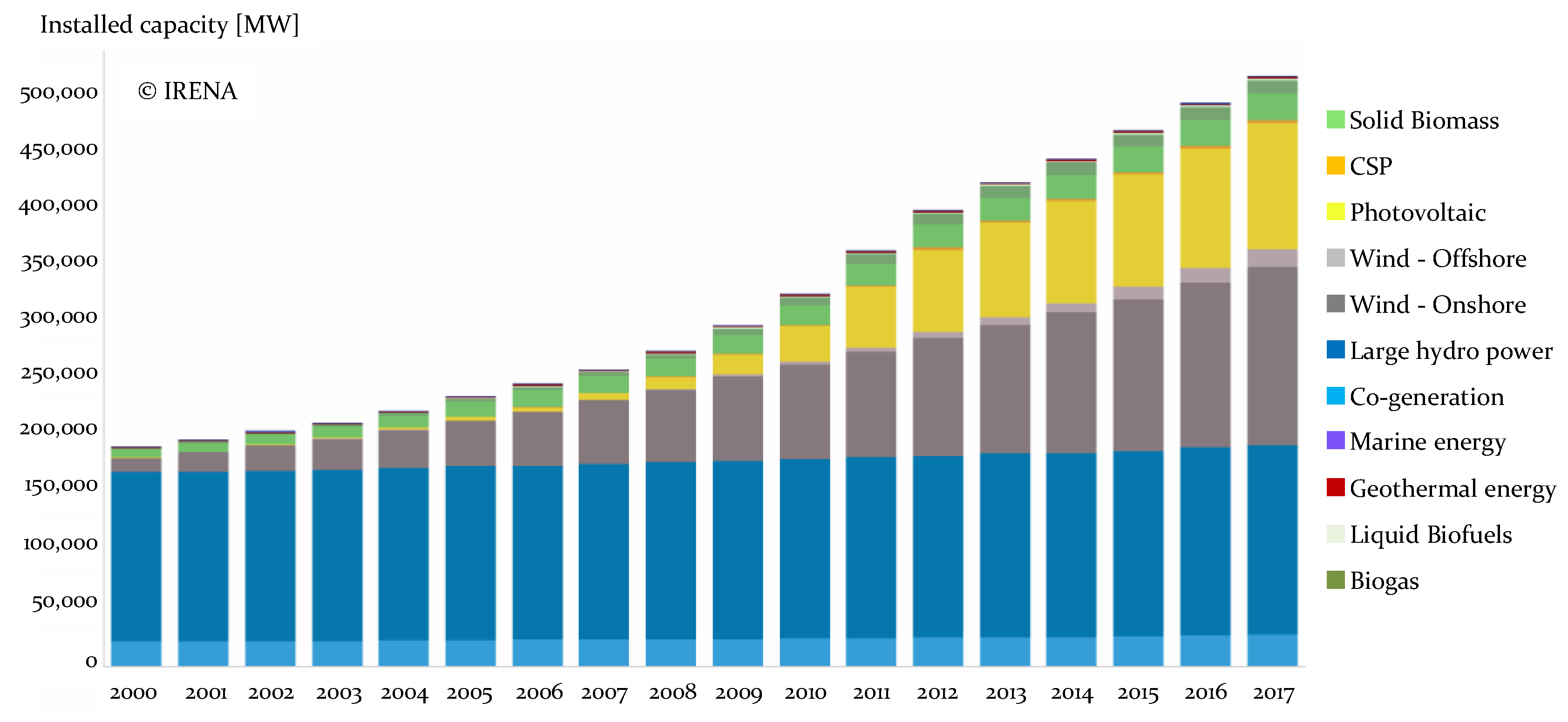
1]. Driven by strong economic and technical incentives, a trend of an increase in the installed capacity can be noted on a regional and a worldwide level, as seen in
Figure 1 (for the European region).
However, with their intermittent nature, DERs can significantly influence the system stability and reliability, especially at the distribution voltage levels. Therefore, in order to motivate the operator to shift towards a more decentralized active distribution system (ADS) and move closer to more sustainable smart grid concepts [
2], the grid connected converter (GCC) will have to assume the responsibility for fulfilling the grid interconnection requirements, i.e., the grid code (GC). As the key component of future power generation systems, the GCC will inevitably be responsible for tasks regarding energy trading, offering fault ride through (FRT) capabilities, and achieving the required power quality for supplying consumers.
On the other hand, achieving such a predefined set of regimes (relevant to the respective GC) under unrated grid voltage conditions can prove to be a difficult task for classical GCC control techniques, especially during unbalanced grid faults. Moreover, many upcoming distribution networks can frequently have voltage asymmetry in the “normal” operating regimes due to unbalanced loads [
4,
5,
6]. This may present the standard GCC control technique with an issue that they cannot resolve, since they are usually not well equipped to deal with asymmetrical grid voltages at the point of common coupling (PCC).
The control strategy of the GCC, as presented in [
7], based on the instantaneous power theory (IPT), can take many different routes (by different proposed strategies), but essentially takes the two following directions—power characteristic oriented control or voltage support oriented control. It should be emphasized that within the different control strategies presented in [
8,
9,
10,
11,
12,
13,
14,
15,
16], special attention has always been reserved for balanced current control. In most of the literature, as in [
8], elimination of the negative sequence current is explained (within the IPT), however, the important issue of cross-coupling between positive and negative sequences has not been discussed. Similarly, in [
10] and [
11], the stationary reference frame (with the well-known issue of initial conditions) was used for the control of currents, consequently leaving out the discussion on the decoupling between positive and negative sequences. Similarly, an linear-quadratic regulator (LQR) controller with resonant elements in state feedback control was used in [
12], while a virtual admittance controller as part of a synchronous power controller was proposed in [
13]. The testing of a relatively complex disturbance observer with a second order general integrator (SOGI) was performed in [
14] using only simulation. The authors in [
15] used generalized sinusoidal pulse-width modulation (SPWM) and a voltage source converter sequence subsystem to balance the current or mitigate DC-bus voltage ripples, avoiding classical controllers and resulting in the dynamic and steady state response being susceptible to parameter variation. In [
16], the double decoupled synchronous reference frame phase-locked loop (PLL) was used for synchronization, with the negative sequence currents regulated using an additional notch filtering in both sequence current control loops. In [
17,
18,
19,
20], mostly harmonic distortion mitigation and synchronization under distorted and asymmetrical voltages were discussed. Considering the previous literature review, the general conclusion can be made that GCC control techniques usually lack the simplicity for implementation in real time that would allow new and existing DERs to operate indefinitely or according to the GC in active unbalanced distribution systems characterized by asymmetrical voltages at the PCC.
This paper aims to showcase the behavior of the standard GCC control technique in active unbalanced distribution systems. Presenting the influence of different grid voltage asymmetry parameters (based on a well-known classification of voltage sags) on the elements of GCC control, the focus will be set on power quality issues and the characteristics of currents injected at the PCC. Within this paper, the authors will explain the methods used for improvement of the main control subsystems that would allow the operation of the GCC under asymmetrical voltages. Subsystems, such as the GCC synchronization unit and GCC negative sequence current control, will be improved or introduced. The improved control technique uses delay signal cancelation (DSC) methodology, in order to differentiate between the positive and negative sequence of the voltage (for the synchronization) and the current (for negative sequence mitigation). Finally, the paper will present the results of an extensive experimental verification. The experiments will include testing the improved control strategy under a significant number of potential grid fault types and voltage asymmetry due to load unbalance.
The main research contributions presented in this paper are as follows:
This paper presents an improved GCC control technique capable of maintaining adequate operation under asymmetrical voltages, showcasing the main benefits in comparison to the classical technique.
The paper gives an extensive experimental verification of the improved technique behavior under different voltage sag types (according to the ABC classification), including operation under the most severe conditions. The developed GCC control technique is an improvement of the classical control technique with relatively low computational complexity and, in that regard, can be implemented in new GCC, as well as in the GCC already existing in the ADS.
2. Grid Connection Requirements in Active Unbalanced Distribution Networks
Systems that allow power flow management in a flexible network topology are, per the International Council on Large Electric Systems (CIGRE) C6.19 workgroup, defined as active distribution systems—an extension from active distribution networks [
21]. The flexible topology refers to a combination of DERs, designated as generators in parallel operation with the distribution system, loads, or storage units [
22]. Consequently, the power flow along the network feeder becomes arbitrary and has to be controlled by a centralized intelligent system that monitors the current network conditions. In such instances, the conventional power flow models become inapplicable [
1,
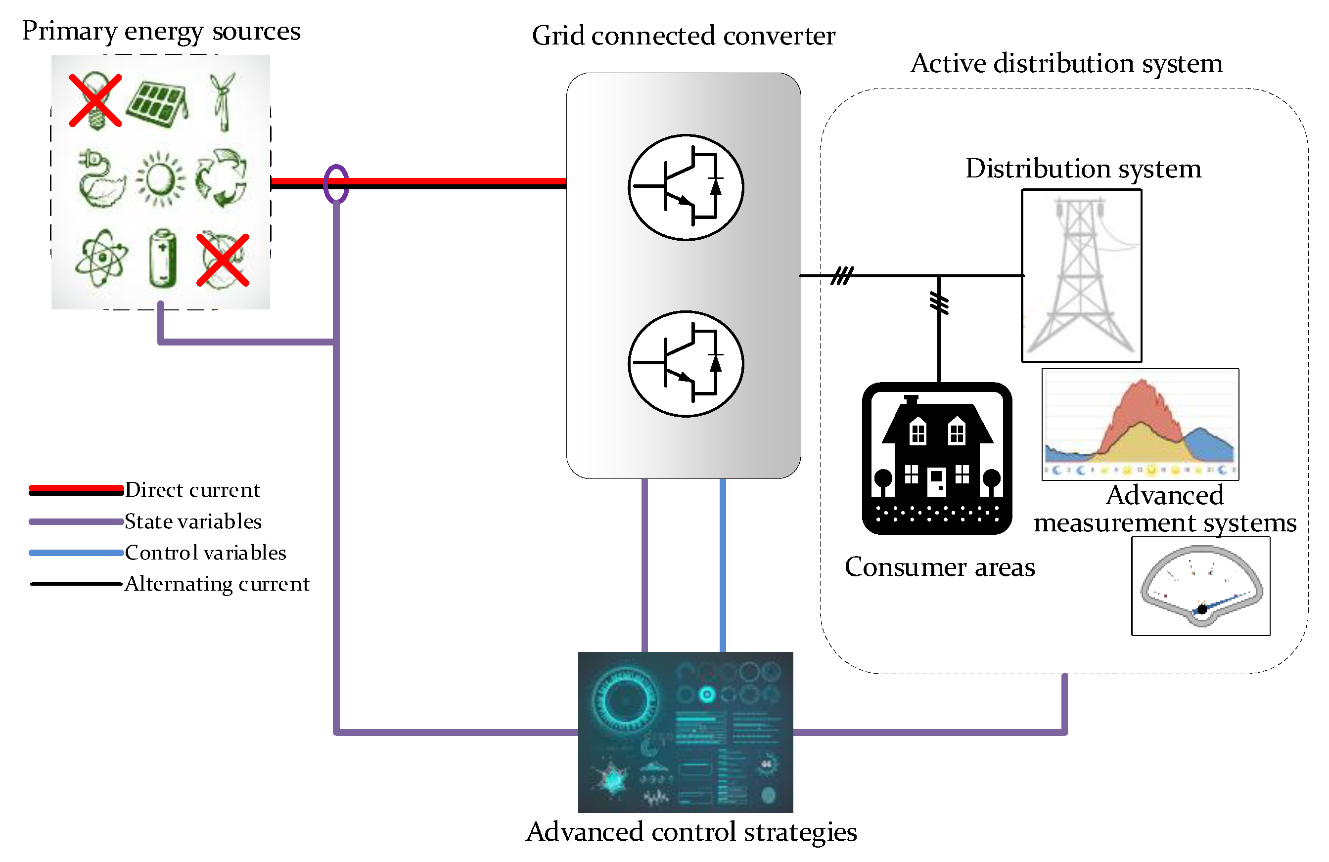
23]. Applications where the GCC are used in parallel operation with the ADS are shown in
Figure 2. State variables in such cases can originate from the ADS operator or primary energy supply, and influence the control variables with different requirements.
Undoubtedly, if high penetration of DERs is achieved with non-dispatchable generation units, ADSs would face more technical uncertainties than the classical distribution network [
24]. Therefore, advanced RES systems will have to, as much as possible, abide by the traditional constraints regarding the connection requirements (power limitation, power quality, short-circuit current limitation). Under special circumstances, where it was impossible to uphold the traditional constraints, a special set of requirements was developed. In order to allow the distribution network operator (DNO) the possibility of ensuring adequate and reliable energy supply, these requirements are collected and published by the relevant DNO in a technical document known as the grid code. Furthermore, these requirements also provide the least possible duration of the connection process and the assurance for DER technology manufacturers during the design process. Usually, all currently available GCs require DERs to possess reactive energy injection, inertia, and oscillation damping to support system transience and steady state stability. Moreover, DERs need to offer voltage support under different grid faults, i.e., offer FRT capabilities. Dictated by the state of the own power system, these requirements may differ worldwide, but they represent the corner stone of every grid code [
25].
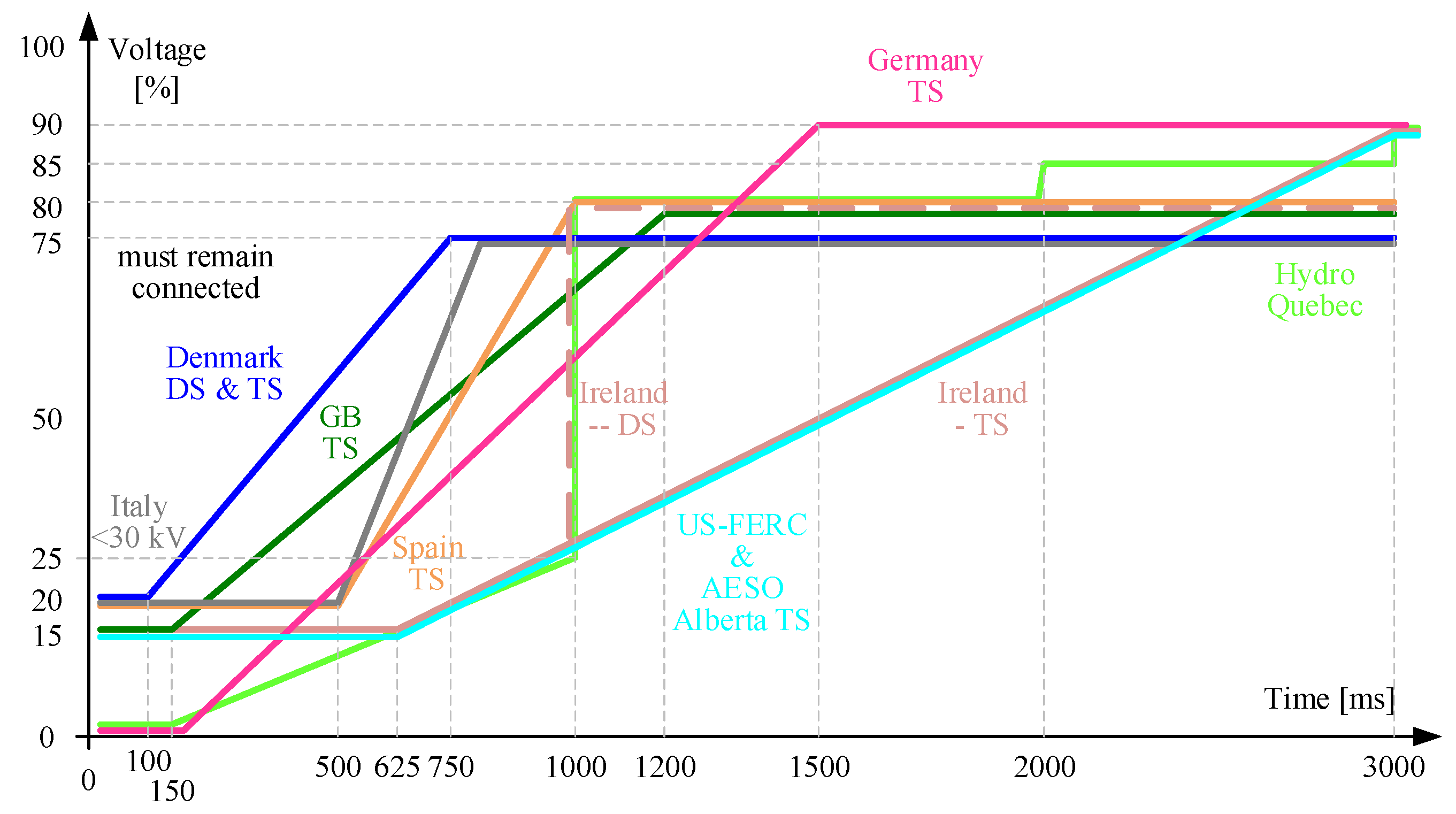
Figure 3 represents the FRT requirements given by the relevant GCs in different countries.
In accordance with the given characteristics, the control of the GCC needs to fulfill two main requirements during grid faults: 1) To remain connected to the grid in the event of grid faults for a requested amount of time, and 2) to support the voltage at the point of common coupling by injecting a requested amount of reactive energy.
As an example, in the case of one of the most developed energy markets, the GCC needs to remain operational in an event of a grid fault for the following duration (given in milliseconds in accordance with the German GC):
where Δ
U designates the relative value of the voltage drop at the PCC. In the same grid code, the reactive current to be injected to the grid is calculated by the following equation:
Achieving these requirements is not a complex task for the classical control technique in case of symmetrical voltages and balanced grid faults at the PCC. However, when grid faults are unbalanced and voltages at the PCC become asymmetrical, the fulfillment of these requirements becomes a fairly hard task. Furthermore, the GCC is required to sustain operation indefinitely under asymmetrical voltages in case of unbalanced grid faults with less than 10% voltage drops or, more importantly, under asymmetrical voltages induced by unbalanced loading in the active distribution system. The most common and frequently used classification of grid voltage sags is the ABC classification based on a simplified network model [
26,
27]. For this particular classification, there are seven distinct types (A–G), as shown in
Table 1, with each one having a different magnitude or phase angle variation. The rated voltage value at the PCC is denoted by
V, while the factor of the voltage value contributing to the fault is denoted by
k (relative voltage drop—can assume values between 0 and 1). While the most natural classification would assume the use of symmetrical components, it is rarely used due to comprehension complexity. It is clear that, albeit being based on incomplete assumptions (simplified network model), the ABC classification, F, is simpler and more convenient for use in different applications.
The voltage sag type, occurring at the PCC, will depend on different factors of the network topology and their combination. First and foremost, the type of the grid fault (balanced or unbalanced) will significantly influence the voltages at the fault location and therefore at the point of measurement (at the PCC). There are four distinct fault types that can occur in the distribution system: Single line to ground fault (SLG), line to line fault (LL), double line to ground fault (LLG), and three phase fault (3P). Balanced grid faults, causing symmetrical voltages, are exclusively related to 3P faults and classified as voltage sag type A. Depending on other factors, LL and SLG faults can result in voltage sag types of B, C, and D, while E, F, and G voltage sag types originate from LLG faults. The transformers, responsible for inner voltage transformation, can influence the voltage sag type, as experienced from the PCC. Since the per unit voltage of the primary and the secondary are equal for the transformers of the Ynyn type, these transformers do not influence the voltage sag types at the PCC. In case of the Dd, Dz, and Yy transformers, the zero sequence voltage will be removed. The most important change comes from the Dy, Yd, and Yz transformers, since they change the line and phase voltages, resulting in an altered voltage sag type in the process. In the same context, the load connection (Y or D) will also significantly affect the voltage sag type at the PCC.
As a logical extension of the ABC classification, the voltage space vector classification was proposed and used in [
27]. The basis for the extension is found in the amplitude invariant Clarke transform, where voltages are represented in a stationary reference frame by the following components:
α,
β, and
zero. The main parameters that define the voltage (ellipse) in the stationary reference frame are the large radius (
rmax), the small radius (
rmin), and the inclination (
φinc). The values of the parameters can be calculated from the positive (superscript
p) and negative (superscript
n) sequence voltages as [
28]:
In order to fully classify the arbitrary voltage sag in regard to the ABC classification, the voltage space vector shape index (SI) can be defined as shown in Equation (4):
The value of the SI represents the compliance of the voltage space vector, with the circular shape achieved by symmetrical voltages at the PCC, where SI = 1 represents a circle, SI = 0 is a two dimensional line, and the ellipse has values in the following range, 0 < SI < 1. Every combination of the values for these four parameters can be classified in one of seven main types of voltage sags (A–G).
3. Control Methodology for a Grid Connected Converter under Asymmetrical Voltages
In accordance with the IPT, the operation of the GCC under asymmetrical voltages at the PCC is significantly more complex for the classical control strategy. First and foremost, the synchronization unit, based on a simple PLL in a synchronous reference frame, is unable to properly estimate the position (angle) of the grid voltage vector represented [
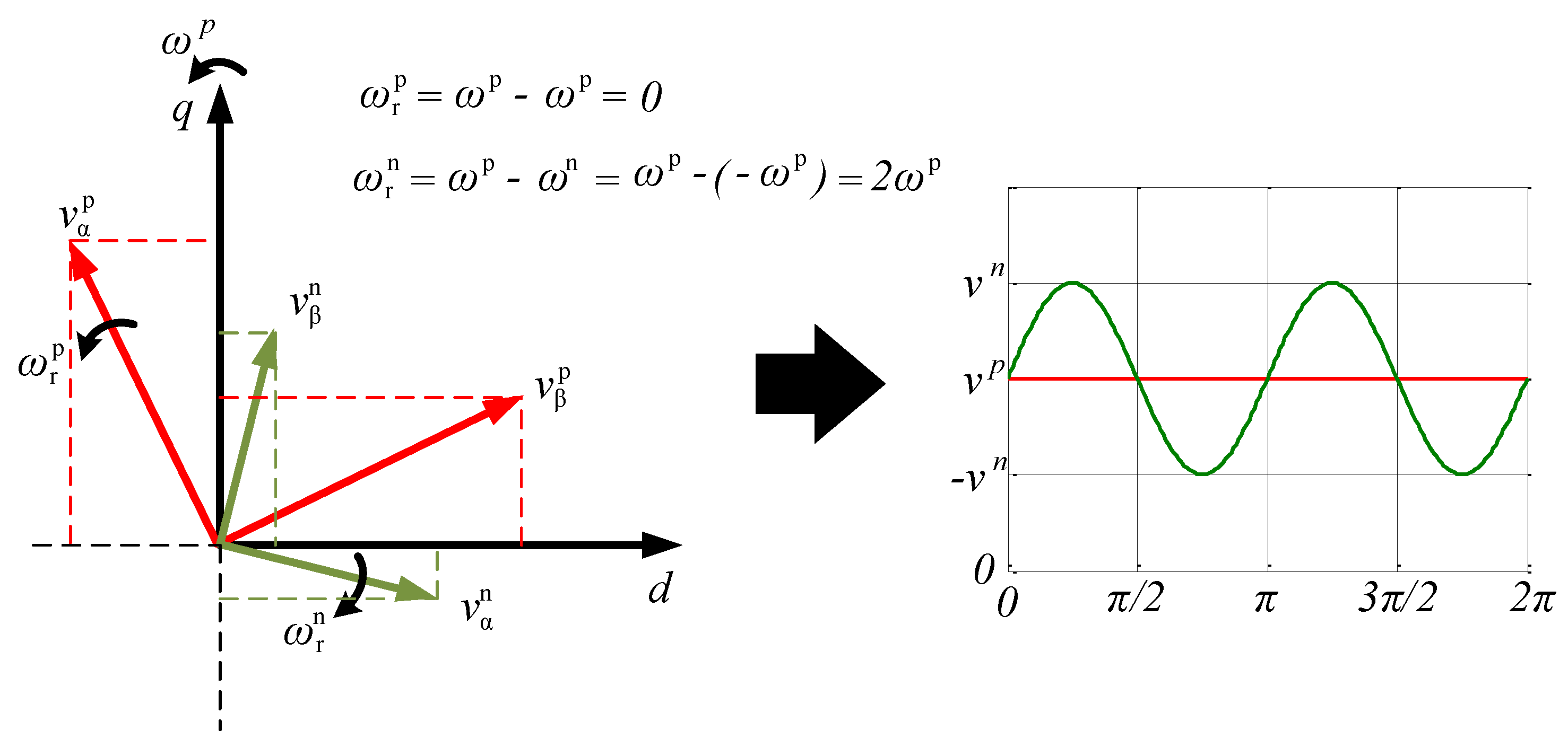
29]. The main issue with the most used synchronization technique is the loop filter that consists of a simple PI type controller, which is inadequate for non-constant value signals at its input. Clearly, when the voltage is asymmetrical, after applying the amplitude invariant Park transform, the resulting value in the synchronous rotating reference frame is a superposition of a constant (positive sequence) component and variable (negative sequence) component at twice the grid fundamental frequency, as observed in
Figure 4 and Equations (5) and (6). The same reasoning holds true for the current control loop as well, where simple PI controllers in the classical technique are insufficient for the control of the desired GCC reference values [
30].
In general, when operating under asymmetrical voltages and currents, the power of the GCC can be given by Equation (7), presenting 4 degrees of freedom to control six variables (powers). However, in order to achieve proper power control of the GCC, decoupling between positive and negative sequences needs to be achieved. The delay signal cancelation technique can be used to separate the voltage and current sequences [
31,
32]. This offers the possibility of individual control of either the positive or negative sequence current, provided the correct reference frame alignment (estimation of the grid voltage vector phase angle). In the digital implementation, the DSC technique can be implemented according to Equations (8) and (9) for the positive and negative sequence, respectively (the expression holds true for both voltages and currents).
where the parameter,
nd, equals a quarter of the ratio between the sampling and the grid frequencies. Due to known issues with the discretization of the DSC technique, special attention should be given to the selection of the sampling frequency, since the mentioned parameter,
nd, should be an integer number. If the discretization introduces a delay time of ΔT to the
ndTs product, the expected error for the negative sequence separation will be:
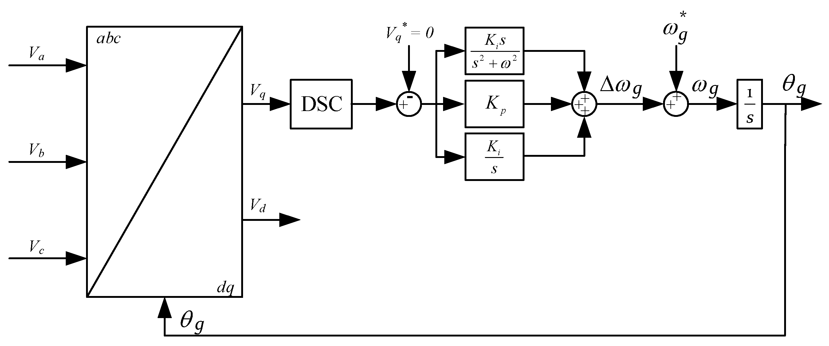
The first step in the proper control of GCC is the accurate estimation of the grid voltage vector phase angle in the direct sequence. However, when asymmetrical voltages are applied to the classical PLL in the stationary reference frame, the loop filter is incapable of making the correct estimation of the angular frequency of the grid voltages. Therefore, an improvement of the classical PLL is necessary for GCC in active unbalanced distribution systems. The proposed DSC technique can be used in the phase detector stage of the PLL for the separation of positive sequence voltages. Additionally, the loop filter can be equipped with the resonant element in order to deal with the possible DSC discretization error and, more importantly, with the higher voltage harmonics at the PCC [
29]. After the addition of the resonant element to the loop filter, the transfer function for the PLL in the synchronous reference frame becomes:
while the overall outlook of the improved PLL unit is presented in
Figure 5.
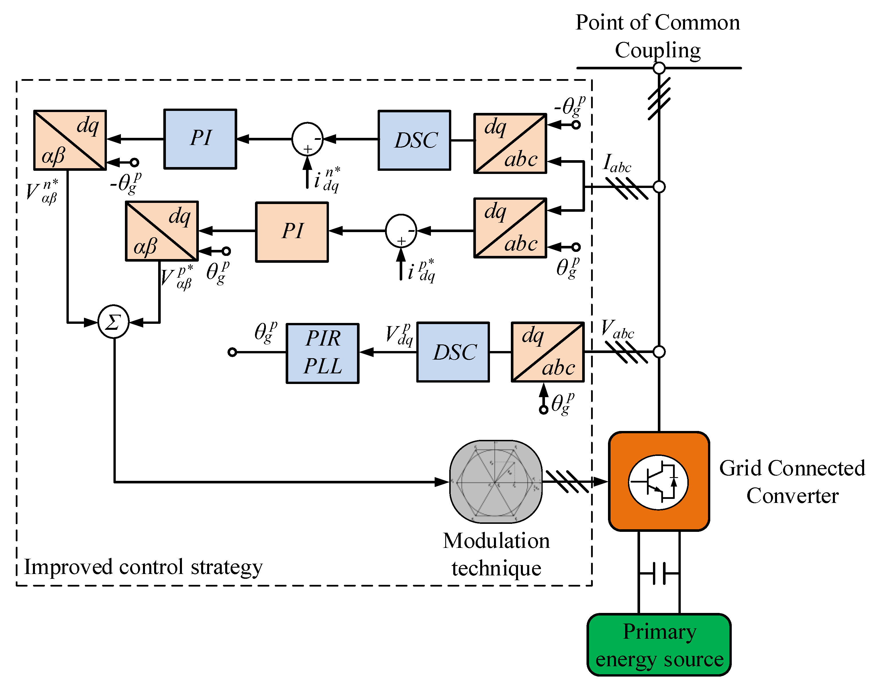
The improved control technique should aim to achieve proper control of the GCC under asymmetrical grid voltages, with the least possible variation of the control strategy in regard to the classical strategy. To achieve such control, while remaining in full accordance to the GC requirements (for the injection of the direct sequence q-axis current), the most reasonable approach assumes mitigation of the negative sequence currents in the synchronous reference frame. If the mitigation of the negative sequence currents was possible, the remainder of the control technique (i.e., the positive sequence current and, therefore, the power control) can remain completely the same.
The improved GCC technique is presented in the
Figure 6. All additional elements that were not part of the classical control strategy have a different background color (light blue). It is obvious that the DSC technique is added only to the negative sequence current controller and the PLL unit, leading to a negligible increase in processing resources. After mitigation of the negative sequence currents, the DSC technique in the positive sequence current control loop would be redundant. Therefore, the current controllers in both positive and negative sequences can be kept from the classical control, i.e., they can be PI type controllers. Furthermore, in the positive sequence current control loop, the parameters for the PI controllers can remain the same. For the PI controller parameters in the negative sequence, the parameters were recalculated using the modified symmetrical optimum method. Considering the fact that the negative sequence current is delayed by
Tg, the integral gain parameter of the PI controller can be calculated as following:
The proportional gain of the controller is kept the same as for the positive sequence currents, i.e., it was calculated using the classical symmetrical optimum given by the following equation:
4. Experimental Verification of the Improved GCC Control Strategy
The behavior of the GCC control under asymmetrical grid voltages was tested on an advanced laboratory prototype, developed at the Faculty of Technical Sciences, University of Novi Sad [
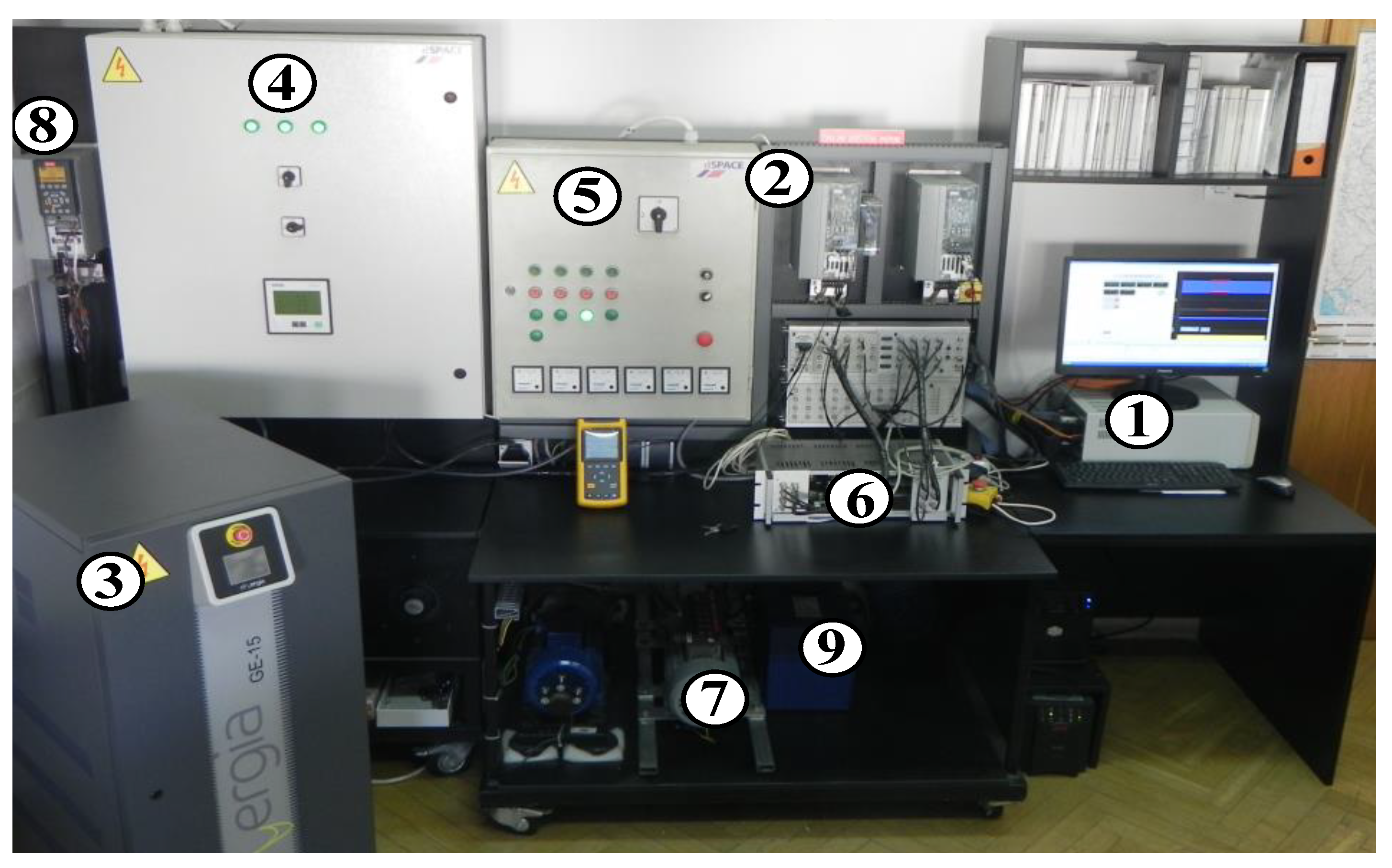
33]. The prototype represents a scaled model of the grid integrated DER and includes state-of-the-art hardware in the field of electrical drives and control, as shown in
Figure 7.
It is based on a modular and highly versatile dSPACE processor board, marked with ①, where the control algorithm for the GCC is implemented. The GCC, marked with ②, is connected to the grid emulator ③, which provides adjustable grid voltages for experimental verification of the technique under different operating conditions (i.e., grid fault) at the PCC. Two distribution cabinets marked with ④ and ⑤ hold the switching and protection gear. Data acquisition, control signals, and measured signals are routed through the adapter block marked with ⑥. Furthermore, different grid integrated DER types (i.e., wind, marine, and solar energy conversion systems, co-generation systems, electrical energy-based storage systems, etc.) can be tested using various electrical machines ⑦, torque-controlled drives that emulate primary energy sources ⑧, and DC/DC ⑨ converters that complete the setup.
In order to compare the standard control technique and the improved control technique proposed within this paper, several experiments were performed, each aiming to show the behavior for different (asymmetrical) voltage conditions at the PCC.
4.1. Experiment I—10% Voltage Sag in One Phase
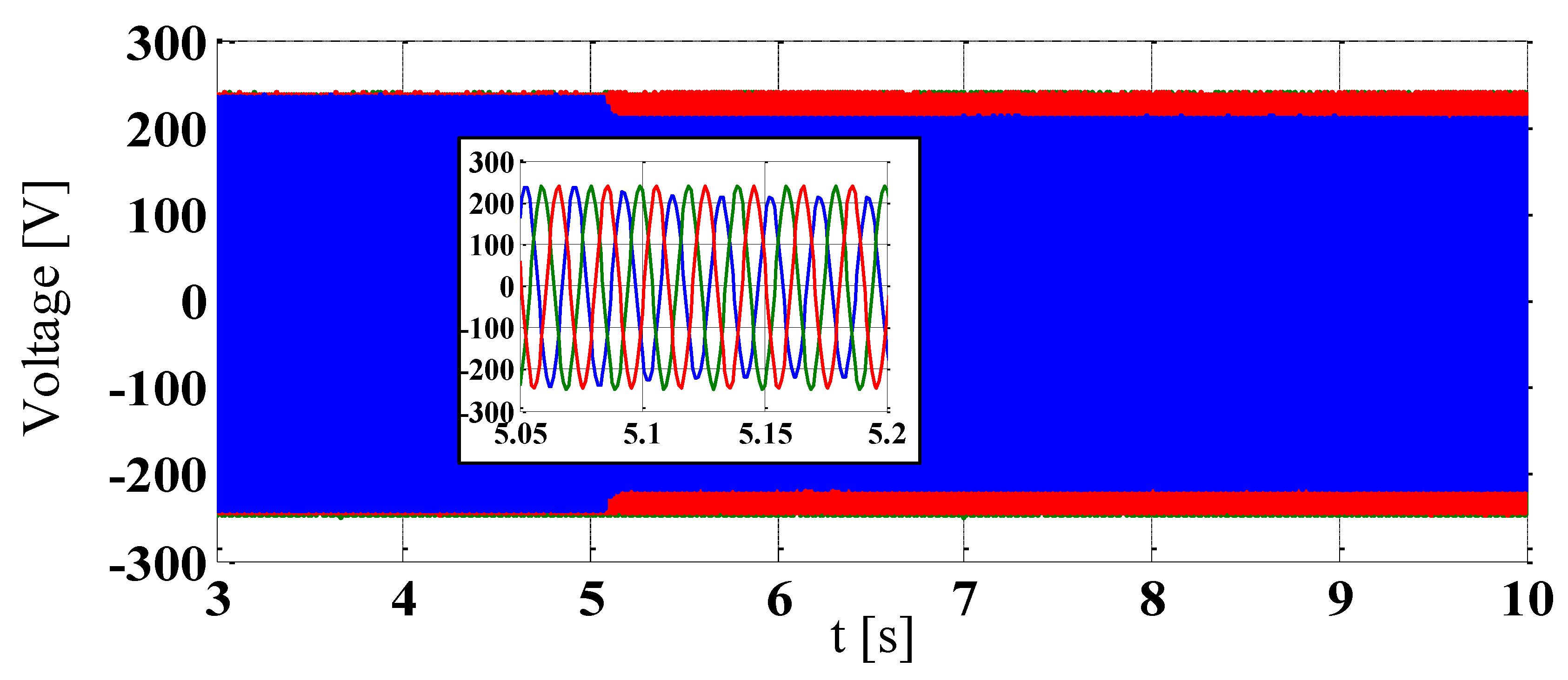
For the first experiment, the classical and improved technique was tested during a simple 10% voltage sag in one phase. The grid voltages waveforms at the PCC are presented in
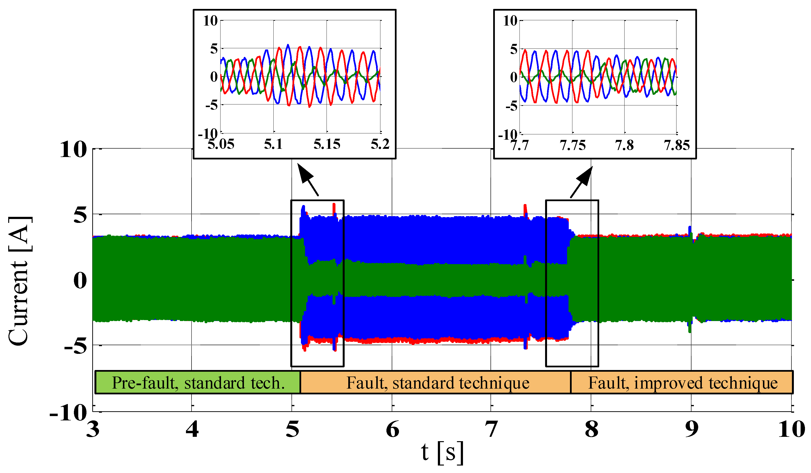
Figure 8, where obvious asymmetry in the voltages is present from the time of 5.1 s onward. This variation of voltage can be classified as a B type voltage sag, while for a magnitude of the voltage sag of only 10%, the GCC would be required to stay connected indefinitely. The current reference during the experiment was set to 3 A of the
d-axis current. As expected, for the standard technique, the control was incapable of achieving a current reference when asymmetrical voltage conditions were applied at the PCC. As presented in
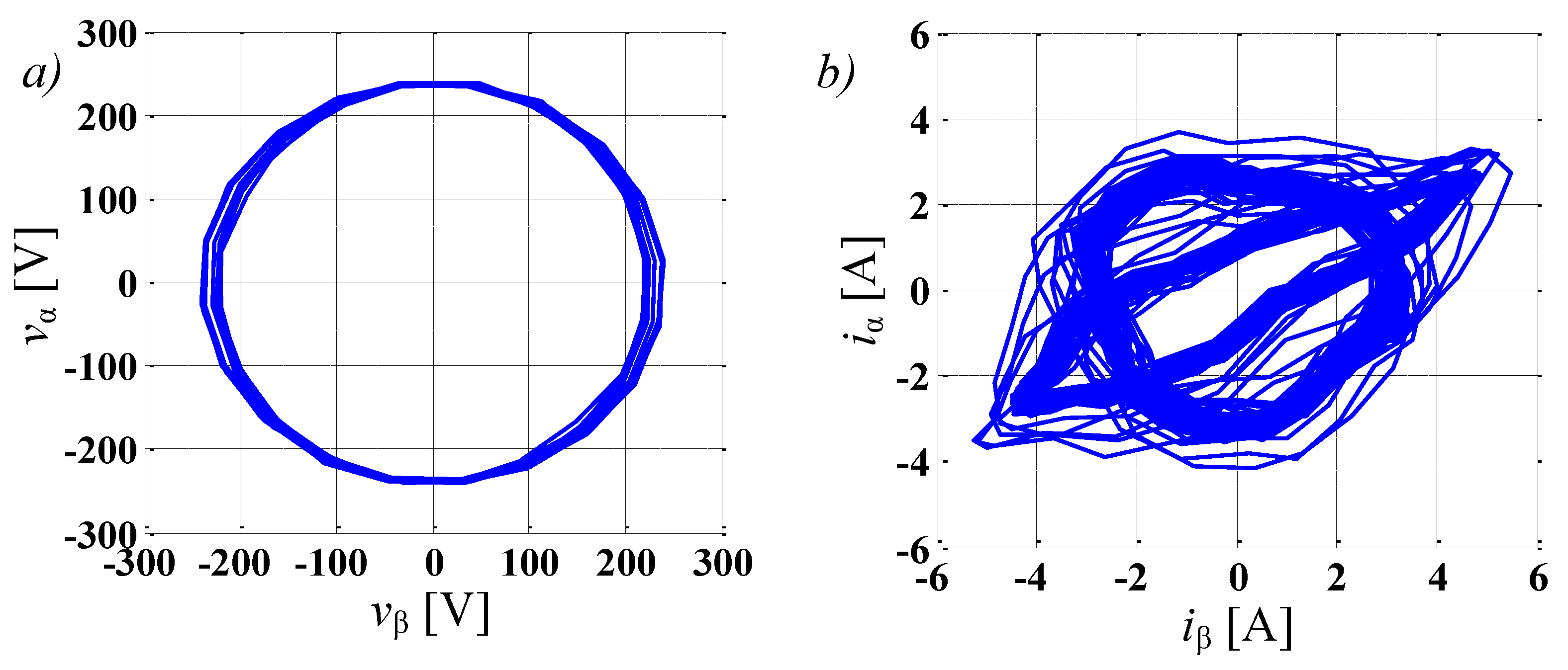
Figure 9 (5.1 s), the currents were clearly asymmetrical, with two currents above (5 A) and one current below (1 A) the set-point value. This operation of the GCC would clearly be inadmissible and the GCC would need to disconnect, violating the GC in the process. Then, at the time of 7.7 s, the control of the GCC was switched from the classical to the improved strategy. Clearly, with a fast transient response, the improved control strategy was able to control the reference to the set-point value of 3 A in all phases. In that instance, full controllability of the GCC was achieved and the currents injected to the grid were symmetrical. The operation of the GCC under the improved technique could therefore be sustained indefinitely. Observing the voltage vector trajectory (
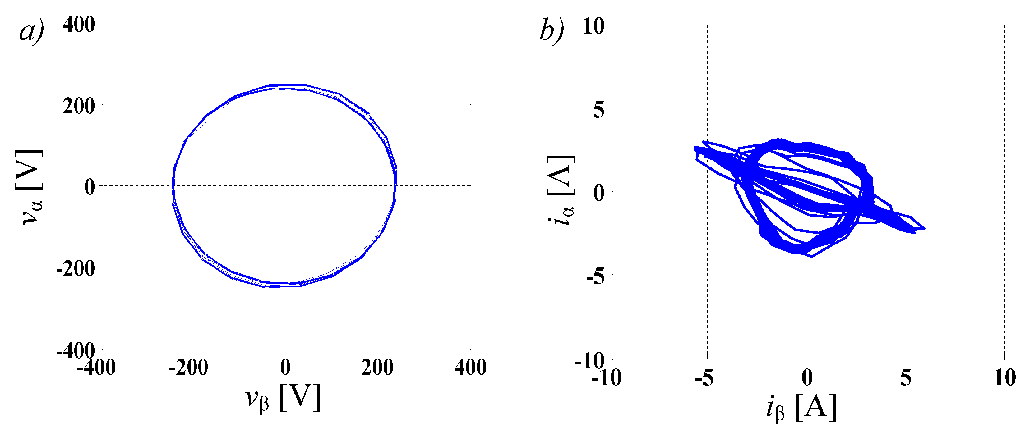
Figure 10a), a slight deviation from the circular shape can be noted. However, for this slight voltage deviation, we can see that the current vector trajectory (
Figure 10b) has a significant shape distortion during the voltage unbalance for the standard control technique, once again clearly supporting the previous statements.
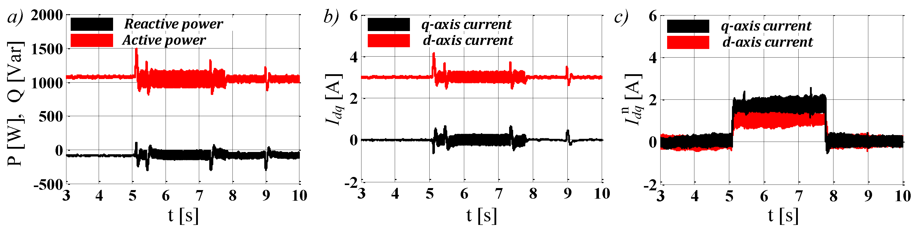
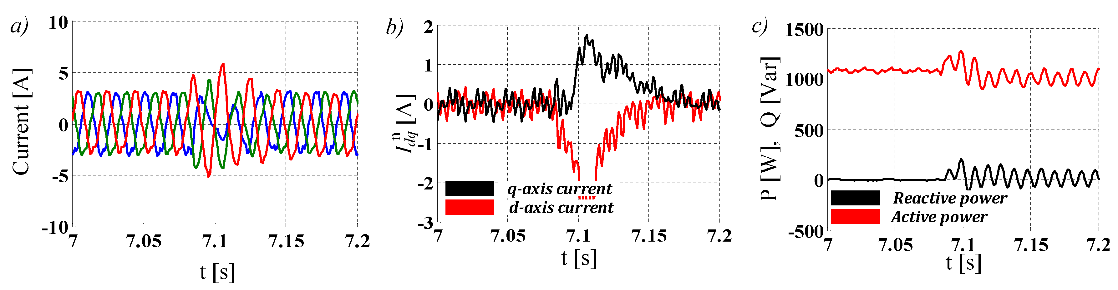
Figure 11a–c show the power, positive sequence currents, and negative sequence currents, respectively, during the first experiment. An oscillating component for both the power and positive sequence currents can be observed during operation under the classical control technique and asymmetrical voltages. The oscillating components correspond to the negative sequence currents as proposed by the theory. After the addition of the improved control strategy, the negative sequence currents are clearly mitigated, which was confirmed by the absence of oscillations in the positive sequence currents. This allows the control technique to remain completely the same for the positive sequence current control. On the other hand, severely reduced oscillations still exist in the power, since the voltages at the PCC are still asymmetrical.
4.2. Experiment II—20% Voltage Sag in One Phase and a 5 Degree Phase Shift
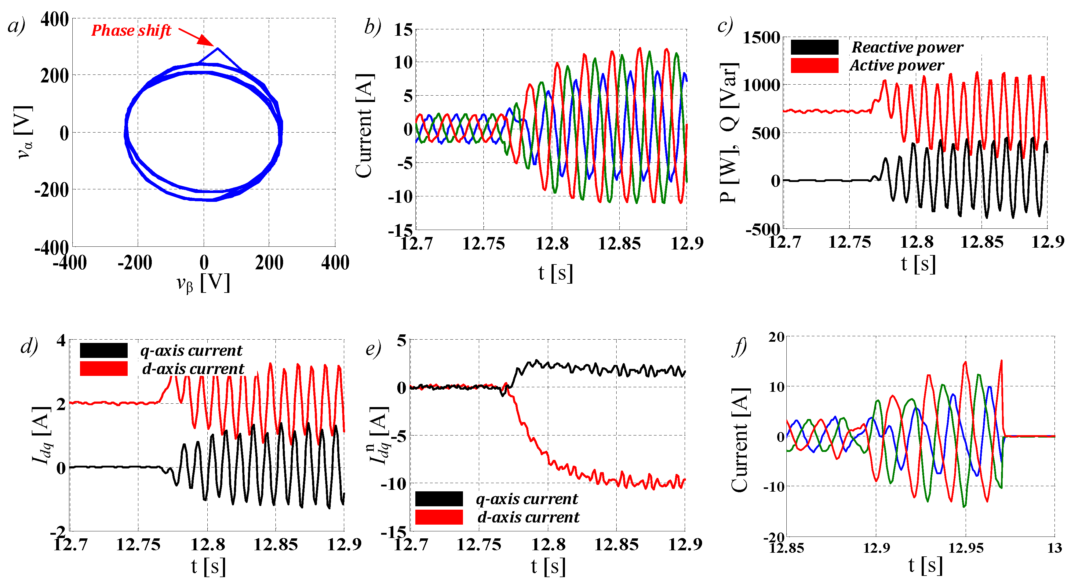
In the next experiment, the GCC standard control technique was tested for a one phase 20% voltage sag with a phase shift of 5 degrees, as seen in
Figure 12a. The
d-axis current reference was set to 2 A and at the time of 12.76 s, the described voltage sag occurred at the PCC. In
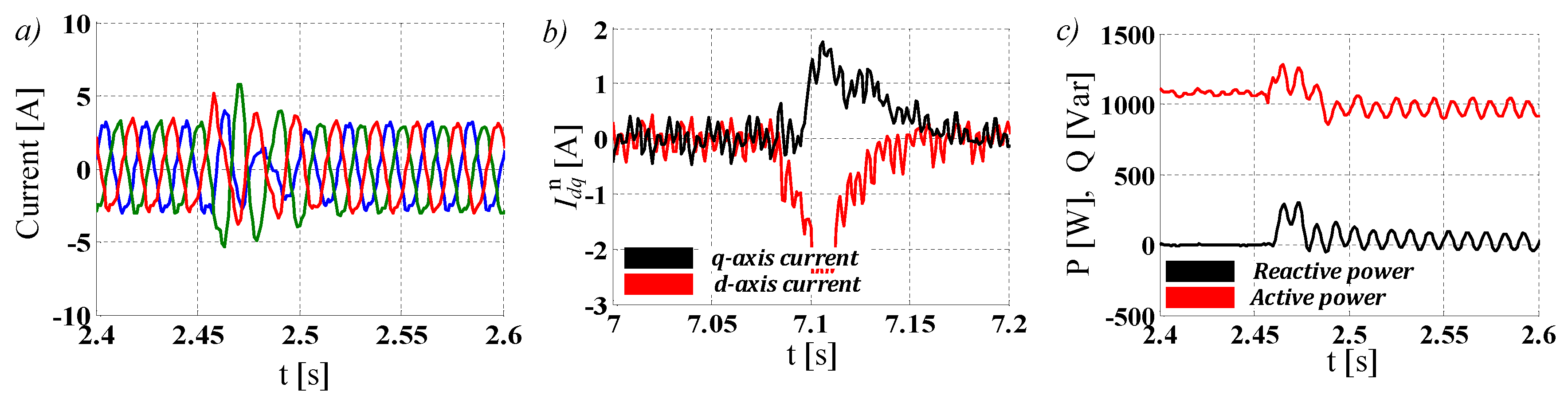
Figure 12b–e, the GCC power, positive sequence currents, and negative sequence currents are presented respectively. It is evident that the standard control technique was incapable of maintaining the controllability of the system, since the injected currents are asymmetrical and significantly higher than the set-point value. The influence of the phase shift on the GCC operation has far more significant consequences, evident from the current waveforms in
Figure 12b, where the current amplitude for the two phases was 11 A. The oscillatory component in the injected power and direct current components also increased. This is a consequence of such a high negative sequence component (
Figure 12e), with 10 A in the negative
d-axis and 2 A in the negative
q-axis. Clearly, operation of the converter would be unacceptable, especially considering that the currents almost reached the protective devices’ current limitation (14 A) of the tested GCC. To fully demonstrate the severity of the fault and the incapability of the standard technique,
Figure 12f shows the operation of the respective GCC under the new experiment with 3 A of reference prior to the fault. When the same fault occurred at 12.87 s, the injected current shot over the set current protection limit (14 A) and the protective device switched off the GCC. In that regard, it would be impossible to operate according to the GC using the standard technique.
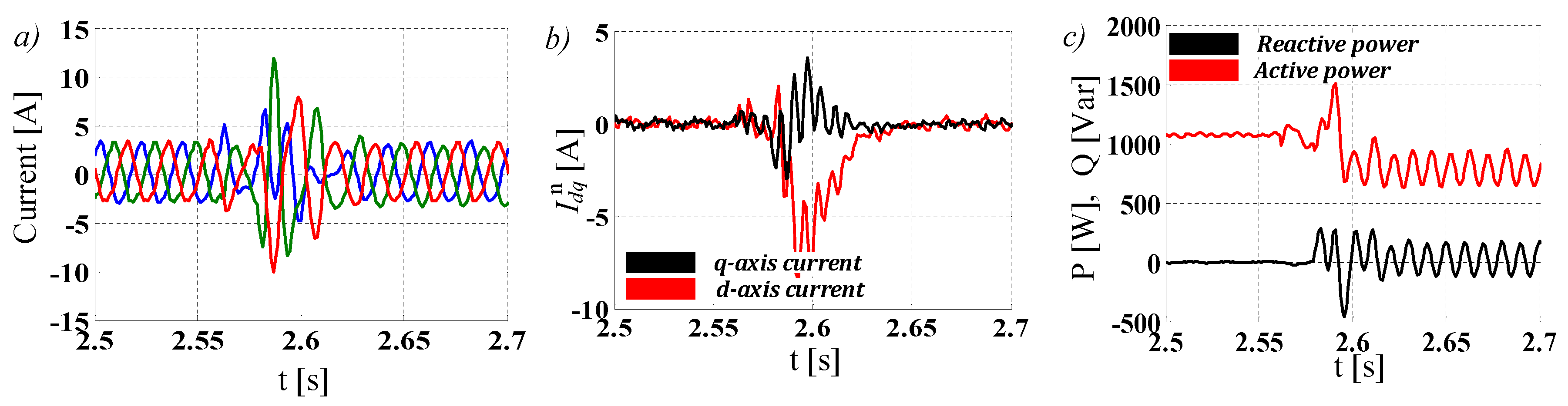
On the other hand, the improved control technique had no issues operating under a 20% voltage sag with a 5 degree phase shift, even for the 3 A reference, as shown in
Figure 13. The improved technique had no issues with the current protection limitation, while the currents were symmetrical both prior and after the grid fault. Since the negative sequence currents were completely mitigated and the oscillations in the injected power were significantly reduced, the operation of the GCC is fully controllable and could be sustained indefinitely or according to the requirements in the GC.
4.3. Experiment III and IV—Voltage Sags Type C and E
Further verification of the improved control strategy was performed for voltage sags type C and type E presented in
Figure 14 and
Figure 15, respectively. The selected type C voltage sag had a parameter of
k = 0.1 (two-phase voltage sag of 8% with the 3 degrees phase shift), while for the type E voltage sag,
k = 0.4 (two-phase voltage sag of 40%), according to
Table 1. Observing
Figure 14 and
Figure 15, it is easy to conclude that the improved technique can extend the range of operation for the GCC, even for the most severe of the voltage sag types. The injected GCC currents are symmetrical, and the negative sequence current is fully mitigated, while the power is controlled, with little oscillation consequent to the grid voltage asymmetry.
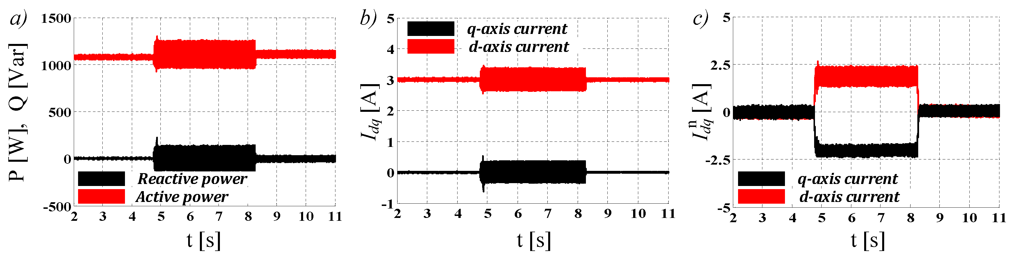
4.4. Experiment V—10% Overvoltage in One Phase
Finally, the techniques were tested against asymmetrical overvoltage at the PCC. The level of the voltage increase is directly related to the distribution network strength (or the network impedance) as observed at the PCC. If the distribution feeder strength is comparable with the integrated DERs power (i.e., high impedance of the network), the voltage at the PCC will consequently begin to increase. In that regard,
Figure 16 presents the GCC phase currents for the classical and the improved technique during the 10% overvoltage in one phase, which would also require the GCC to remain connected indefinitely. The reference for the
d-axis current was set at 3 A prior to the fault that occurred at the time of 4.75 s. The classical control technique had the expected behavior, with the asymmetrical currents of 5 A (two phases) and less than 1 A (one phase) injected to the grid at the PCC. After the application of the improved control technique, full controllability was restored, with symmetrical currents clearly regulated to the desired set-point. The shift in voltage trajectory, presented in
Figure 17a, can be regarded as insignificant. However, after observing the current vector trajectory in the
Figure 17b, it can be concluded that the influence of the overvoltage on the GCC control strategy is evidently higher (for the same relative variation) than the influence of the voltage sag. Once more, the known oscillations at twice the grid frequency occur in the injected power (
Figure 18a) and positive sequence currents (
Figure 18b). Negative sequence currents, with almost identical values for both the
d- and
q-axis, are differentiated just by the sign (
Figure 18c). After the improved control strategy was applied, the negative sequence currents were successfully mitigated, lessening the oscillations in the injected power and positive sequence currents.
These experiments clearly demonstrate that the improved control technique can sustain indefinite operation of the GCC under any kind of asymmetrical voltage conditions present at the PCC, even where the standard technique would hit the current protection limitations. In all cases, mitigation of the negative sequence currents led to full controllability of the GCC, with most of the control technique in the positive sequence remaining completely the same.
5. Conclusions
Considering the importance of DER, especially in the present active (and unbalanced) distribution systems, the operation of the GCC under asymmetrical voltage conditions at the PCC will become the most important issue going forward. Since the classical control technique has certain deficiencies when asymmetrical voltages are applied at the GCC input, improvements are necessary in order to fulfill the strict future requirements outlined in the GC. This paper presented an improved control strategy, with relatively simple implementation, aimed at the mitigation of negative sequence currents. The presented strategy maintained the control in the positive sequence at the same level as in the case of the classical strategy, making it a perfect fit for existing grid integrated DERs, as well as for new systems. The improved technique was extensively verified for different voltage sag types (including B, C, and E), arbitrary voltage conditions, as well as for scenarios where asymmetrical overvoltage occurs at the PCC. Not usually tested in the literature, voltage drops with phase shifts and overvoltage can prove to be very demanding scenarios. However, the proposed technique had no problems with dealing with even the most complex grid faults, achieving a great dynamic performance, while, simultaneously, GCC controllability was restored. This offers an extended range of GCC operating states, making it possible for the GCC under asymmetrical voltages to operate indefinitely or according to the relevant GC. Further research will be aimed at introducing additional algorithms to the improved technique in order to offer dynamic grid support capabilities, i.e., special FRT requirements under different voltage asymmetry levels in active unbalanced distribution systems.


