Article

A Method for Rapid Evaluation of Thermal Performance of Wall Assemblies Based on Geographical Location

Department of Materials Engineering and Chemistry, Faculty of Civil Engineering, Czech Technical University in Prague, 166 29 Prague 6, Czech Republic
*
Author to whom correspondence should be addressed.
Energies 2019, 12(7), 1353; https://doi.org/10.3390/en12071353
Submission received: 11 March 2019 / Revised: 4 April 2019 / Accepted: 7 April 2019 / Published: 9 April 2019
(This article belongs to the Special Issue Heat and Mass Transfer in Building Energy Performance Assessment)

Abstract

:
In this study, we present a method for the rapid evaluation of thermal performance of building envelopes without the need of using sophisticated and time-consuming computational modeling. The proposed approach is based on the prediction of monthly energy balances per unit area of a wall assembly using monthly averages of temperature and relative humidity, as well as the elevation of a building’s location. Contrary to most other methods, the obtained results include how moisture content in the wall effects its thermal performance. The developed formulas for calculation of monthly energy balances are verified for nine commonly used wall assemblies in Central Europe in 10 randomly selected locations. The observed agreement of the predicated data was determined using advanced finite-element simulation tools and hourly climatic data, which makes for good prerequisites for the further application of the method in both research and building practices.

1. Introduction

A fundamental objective of building enclosures is to protect occupants from weather effects. Therefore, each part of a building envelope needs to meet certain thermal requirements in order to create a comfortable interior environment. A good thermal performance of building envelopes is very important in order to minimize overall energy consumption. Besides industry and transportation, residential households are one of the largest energy consumers in the European Union (EU). According to an EU report [1], 25.4% of total energy is consumed by residential houses and 70% of that amount is represented by heating energy [2]. This means that significant energy savings can be achieved by improving the effectiveness of heating systems or thermal insulating capabilities of building envelopes, which are required by national thermal standards.
Currently, when a building envelope is being designed or assessed, the U-value (thermal transmittance) is mostly used to indicate its insulating capabilities. It is a basic quantity describing the thermal insulating capability of building constructions; its required values are prescribed for each part of a building in any European country [3,4,5]. The U-value calculation is based on steady-state loading conditions and mostly comes from laboratory measurements [6,7,8,9]. However, there are several drawbacks to its laboratory methods. First, the accuracy is not always sufficient, as the effect of moisture on thermal conductivity of building materials is often neglected [10,11,12]. Although the national standards define design values of thermal conductivity and assume a certain level of operational moisture content, the thermal conductivity of building materials can significantly differ in the real conditions due to weather effects and presence of liquid moisture. Second, external thermal loads on building walls in real conditions are not steady. This may be due to changing outdoor conditions, such as temperature, relative humidity, wind speed, precipitation, and/or solar radiation.
Since the climate is comprehended as a local variable, it is apparent that geographical location affects significantly the thermal performance of individual wall assemblies. For that reason, many research studies have been aimed at the investigation of differences between laboratory and on-site thermal performance of building materials, components, or whole buildings. Byrne et al. [13] pointed out that predicted values of heat loss using standardized assumed material properties of the existing structure do not reflect the actual values achieved in situ. Marchio and Rabl [14] compared the predicted and observed performance of selected houses and apartments in France. Branco et al. [15] compared predicted and performed heat consumption of low energy family house in Switzerland. Roels et al. [16] provided an extensive comparison of various assessment methods for on-site characterization of the overall heat loss coefficient. Ficco et al. [17] conducted experimental measurement of in situ U-values and compared them against the estimated ones from design data and field analyses. The traditional empirical rules or standardized methods for U-value calculation were thus found not to work effectively, which was due to the high variability of the environmental and material properties or insufficient quality of input data. For a more proper assessment of thermal performance of building enclosures, more advanced techniques were supposed to be incorporated. Therefore, some new approaches for determination of thermal performance were suggested. For example, Robinson et al. [18] outlined a new transient, straightforward, and low-cost method for estimating the thermal properties of wall structures. Byrne at al. [19] designed a facility for testing the thermal properties of wall samples under both steady and transient conditions. Perilli et al. [20] performed a numerical analysis of thermophysical behavior of cork insulation based on in situ experimental data. Some other advanced techniques were applied, for example, for the analysis of the effect of wind velocity on quantification of heat losses through building envelope thermal bridges [21], the estimation of overall heat loss coefficient [22], convective heat transfer coefficient of exterior surface of building walls [23], or the prediction of residential heating demands [24].
In this paper, a method for rapid quantification of thermal performance of exterior wall systems is designed, which is intended to provide the designers and engineers with a fast and efficient tool for thermal design of residential buildings. The approach is based on the development of formulas for the calculation of monthly energy balances that only use monthly averages of temperature and relative humidity and the elevation of building’s location as input parameters, but can achieve similar accuracy as advanced computational methods utilizing robust finite-element simulation tools and hourly climatic data. At the development of the calculation formulas, climatic data for 50 locations across the Czech Republic are used as a training set. The data for other 14 Czech locations are utilized as a testing set in the first step of the verification procedure. Another set of weather data for 10 randomly selected European locations are obtained from the Meteonorm software [25] and is used in the second verification step. The application of the method is presented for nine common wall systems, but it can be extended to any other type of building wall.

2. Methods

2.1. Climatic Data

For the investigation of thermal performance of the analyzed wall assemblies, 64 locations across the Czech Republic were selected and the weather data from those locations were collected. To ensure the widest range of weather data possible, the selection covered both lowlands and mountains across the country. All weather data were obtained from the Czech Hydrometeorological Institute, which is the official authority for meteorology, climatology, hydrology, and air quality protection in the Czech Republic. All data were applied in the form of the Test Reference Year (TRY) [26,27,28]. The data included hourly values of temperature, relative humidity, precipitation, wind direction, wind velocity, diffuse and direct short-wave radiation, sky long wave emission radiation, and long wave emission radiation. The list of involved locations together with their elevations is shown in Table 1.

2.2. Studied Wall Assemblies

The investigation of thermal performance was carried out for various types of both historical and contemporary building enclosures commonly used in Central Europe. Load-bearing materials included concrete (C), ceramic brick (CB), advanced hollow bricks (AHB), and sandstone (S). The contemporary building envelopes were provided with different types of thermal insulation layers based on expanded polystyrene (EPS) and mineral wool (MW), while the historical masonry did not have any thermal insulation. Exterior plasters were chosen with respect to the material composition of the envelopes, such as lime-cement plaster (LC), renovation plaster for historical masonry (RPHM), or lime-pozzolan plaster that was specially developed for the advanced hollow bricks (LPC). On the interior side of all structures, 10 mm thick lime-cement plaster was assumed. The list of studied building enclosures is shown in Table 2.

2.3. Computational Simulation

In order to simulate heat transfer through investigated wall assemblies, a 1-D simulation of heat and moisture transport through the building walls exposed to the exterior environment was conducted. Further, to increase the accuracy of thermal performance, the study included moisture transport to the heat transfer modelling with a straight intention, as moisture can significantly influence heat transport and storage parameters of building materials. In the formulation of the mathematical model of heat and moisture transport in multicomponent porous building material systems, a modified version of the Künzel’s [29] mathematical model was used [30]. The modification of the original model was motivated by the effort of increasing the numerical stability, output accuracy, and reducing the overall time of computation. The heat and moisture mass balance equations can be expressed as:
d H d T T t = d i v ( λ g r a d T ) + L v d i v ( δ p g r a d p v )
[ ρ w d w d p v + ( n w ) M R T ] p v t = d i v [ D g g r a d p v ]
where H (J·m−3) is the enthalpy density, T (K) the absolute temperature, λ (W·m−1·K−1) the thermal conductivity, Lv (J·kg−1) latent heat of evaporation of water, δp (s) the water vapor diffusion permeability, pv (Pa) the partial pressure of water vapor in the porous space, ρw (kg·m−3) the density of water, w (m3·m−3) the moisture content by volume, n (-) the porosity of the porous body, and M (kg·mol−1) the molar mass of water vapor, and R (J·K−1·mol−1) is the universal gas constant. Dg (s) is the global moisture transport function defined as:
D g = B · D w ρ w d w d p v + A · δ p
where A and B in Equation (3) are the membership functions defining the transition between particular phases of water, which can be formulated as:
B = { 0 φ 0 ; 0.9 ) 32 [ ( 1 p v 2 p v 1 ) ( p v p v 1 ) ] 6 φ 0.9 ; 0.938 ) 1 32 [ ( 1 p v 2 p v 1 ) ( p v 2 p v ) ] 6 φ 0.938 ; 0.976 ) 1 φ 0.976 ; 1
A = 1 B ,
where the partial pressures of water vapor pv1 and pv2 (Pa) define the transition region. In this paper, the values of pv1 and pv2 correspond to the values of relative humidity of 90% (φ = 0.9) and 97.6% (φ = 0.976), respectively.
The computational model was implemented into an HMS simulation tool (Heat, Moisture and Salt transport), which is based on the general finite element package SIFEL (Simple Finite Elements) [31]. Both tools were developed at Faculty of Civil Engineering, Czech Technical University in Prague. HMS has been successfully used and validated in the recent past [32]. Each wall assembly was discretized from 29 to 41 nodes depending on its thickness and finite element method was applied. For the solving of partial differential equation, a non-linear, non-stationary solver with adaptive time controller was employed. A short survey of basic physical, thermal, and hygric properties used in the computational simulations is presented in Table 3 and Table 4, where the following symbols are used: ρv is the bulk density, ρmat is the matrix density, ψ is the total open porosity, λ is the thermal conductivity, c is the specific heat capacity, μdry-cup is the water vapor diffusion resistance factor in dry-cup arrangement, and κapp is the apparent moisture diffusivity. Those parameters were used in the computational model (1)–(5), either directly (such as thermal conductivity) or recalculated (water vapor diffusion resistance factor into water permeability, bulk density, and specific heat capacity into derivation of enthalpy density). Some parameters in Table 3 and Table 4 have informative character only (matrix density and open porosity). More details on the particular parameters, such as their dependence on moisture content, can be found in the original references listed in Table 5.
The exterior environment was simulated using weather data from stations listed in Table 1, whereas the interior conditions were kept at 21 °C and 55% of relative humidity during the whole year. The initial conditions were same as interior boundary. Each simulation was run for 10 years in order to avoid the results being affected by initial conditions. The data from the last year of the simulation were used for further analysis.
The solar radiation and precipitation are important factors affecting the heat flux at interior wall surface. Therefore, it is very important to include those effects into the computational model in order to be able to predict monthly heat fluxes affected by both precipitation and solar radiation. The orientation of the wall plays a crucial role regarding the solar radiation and precipitation loads. As the proposed methods evaluate the average values of monthly heat fluxes from north and south orientation, a detailed analysis needs to be performed in order to investigate the model accuracy, as well as to analyze the effect of precipitation and solar radiation. The results of such an analysis are shown in the Discussion section.

2.4. Assessment of Thermal Performance

The quantification of thermal performance of the studied walls was done on the basis of calculation of time development of heat flux density q(t) on the interior surface of the construction during a year. The heat flux densities were determined as:
q ( t ) = λ i p ( w , t ) Δ T e ( t ) Δ x e
where λip(w,t) (W·m−1·K−1) is the moisture-dependent thermal conductivity of the interior plaster, Δxe (m) is the thickness of the element adjoining to the face side of the wall in the main direction of the heat flux, and ΔTe (K) is the temperature difference between the opposite sides of the element adjoining to face side of the wall in the main direction of the heat flux. When the heat flux density as a function of time during a year is known, the monthly energy balances EB1EB12 of the wall assembly can be evaluated as a sum of heat flux densities during individual months. In the calculations of monthly balances, the positive values represent monthly heat gains (i.e., the necessity of cooling to keep interior temperature at prescribed level), while negative values represent monthly heat losses (i.e., the necessity of heating). As individual months of the year contain different number of days, the calculated values of energy balances were normalized to 30-day period allowing mutual comparison between the months. Monthly periods were chosen as a compromise between computational efficiency, model accuracy, and data availability.

2.5. Identification Procedure

The identification of the relation between thermal performance of studied walls and the weather data of certain locations was based on the optimization procedure. The objective of that procedure was to minimize the difference between predicted and simulated thermal performance (monthly energy balances) by identifying unknown correlation coefficients. From the weather data listed in Table 1, locations 1 to 50 were used as a training set, i.e., set of data on which the identification was carried out. The remaining data from locations 51 to 64 were used as a testing set, i.e., those data were excluded from the identification procedure and once the identification was finished, they were used for the verification of identified correlation coefficients. In order to assure the highest simplicity possible, the predicting formula for monthly energy balance of each studied wall assemblies was optimized in the linear form as:
E B i , p r e d = c 0 + c 1 · T i + c 2 · R H i + c 3 · E
where i = 1, 2, …, 12 indicates the month, EBi,pred (W·h·m−2·month−1) is the predicted monthly energy balance of wall assembly in particular location, Ti is the average monthly temperature in particular location, RHi the average monthly relative humidity in particular location, E is the elevation, and c0c3 are correlation coefficients unique for each building wall listed in Table 2. The average monthly values of temperature and relative humidity for all locations are presented as supplementary data in Tables S1 and S2. The data on elevation were provided in Table 1.
As the identification procedure was based on minimization of the difference d between simulated and predicted monthly energy balances over multiple locations, the objective was to find such combination of c0c3 for each of studied walls that fulfills
d = min ( n = 1 50 i = 1 12 E B i , s i m E B i , p r e d ( c 0 , c 1 , c 2 , c 3 ) )
where n is the location number (see Table 1) and EBi,sim (W·h·m−2·month−1) is the simulated monthly energy balance using computational model (1)–(5).

3. Results

3.1. Identification Procedure

Prior to the identification procedure, computational simulations of nine building envelopes that were exposed to the effect of environment in 64 different locations were conducted. Moreover, each building envelope was investigated in two different orientations—north and south—in order to include the effect of solar radiation and wind direction in each location. In total, 1152 simulations were carried out, which the monthly heat flux densities as a function of time were calculated from. The final heat flux density for each building wall and location was calculated as an average of north and south orientation and the monthly energy balance of each wall under different location was then calculated from monthly sequences of heat flux densities. The obtained results were normalized to 30-day period and in this way 576 input values for the identification procedure were generated.
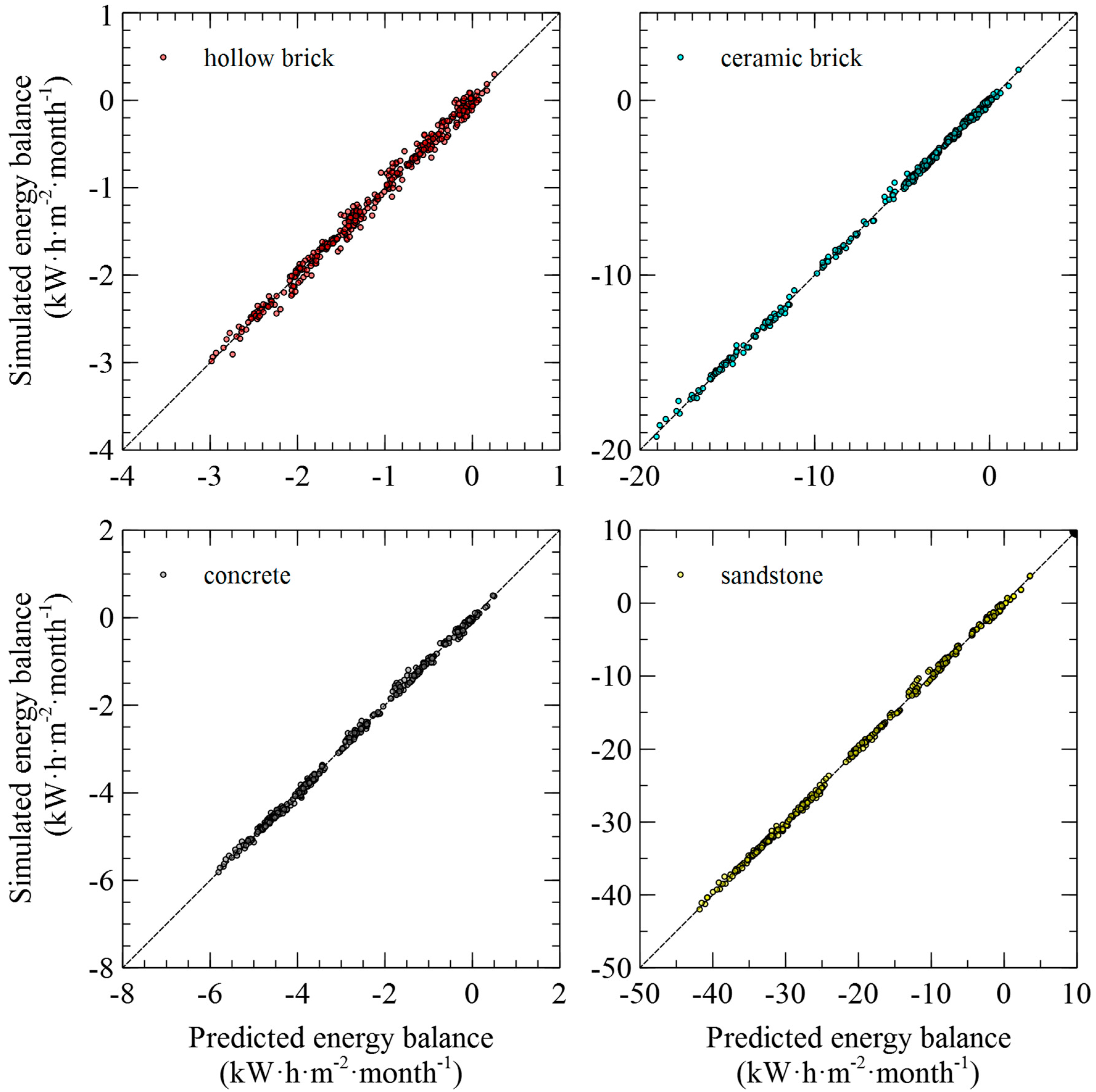
In the identification procedure, the correlation coefficients for each wall assembly listed in Table 2 were identified on the training set that consisted of locations 1–50 from Table 1. Then, the identified correlation coefficients were verified on the testing set given by locations 51–64 from the same table. The identified correlation coefficients from the training phase together with the coefficient of determination (R-square) between simulated and predicted data are presented in Table 6. In this table, BE# refers to the building envelope numbers as listed in Table 2. The visual comparison between simulated and predicted data in the training phase of the identification is shown in Figure 1, where the studied wall assemblies are grouped into four categories by the load-bearing materials. Similar grouping is used further in the manuscript.
It is obvious from Figure 1 that the identified correlation coefficients allowed to predict the monthly energy balance per unit area of the wall with a very high accuracy. Best results were achieved for sandstone masonry, while the worst agreement was observed for hollow brick masonry. The average prediction error between simulated and predicted values of monthly energy balance of individual wall assemblies was between 1.69% (sandstone masonry) and 6.43% (hollow brick masonry). The R-square was ranging between 0.9852 and 0.9991, which justified the utilization of linear formula in the identification procedure.
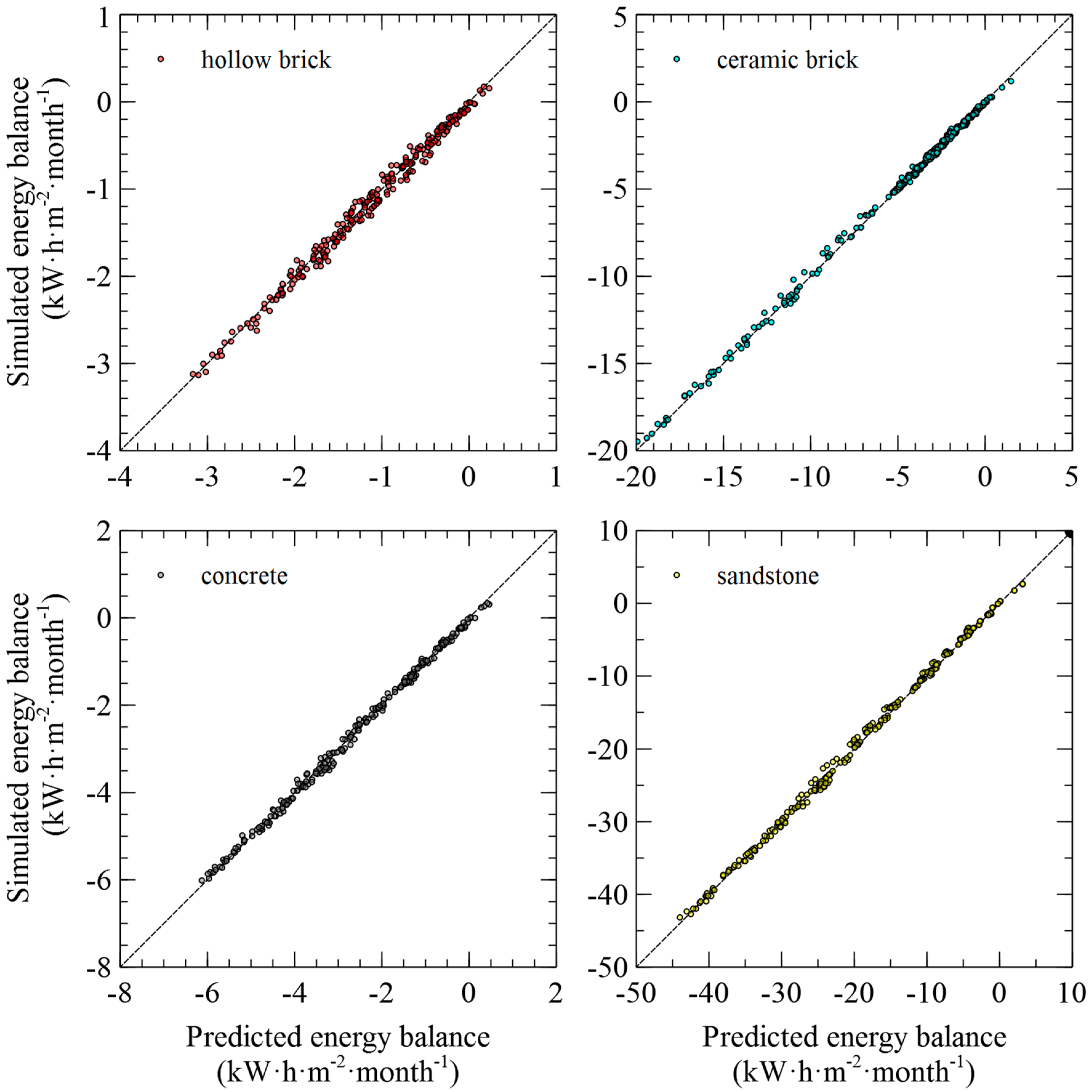
With the identified coefficients from Table 6, the testing procedure was run for each one of studied wall assemblies in order to verify the accuracy on blind data. This means, that remaining 14 localities, which were excluded from the training procedure were now tested with identified correlation coefficients c0c3. The results of testing procedure are shown in Figure 2. The agreement between predicted and simulated data was very good, showing excellent setup of correlation coefficients. The average prediction error between simulated and predicted values of monthly energy balance of individual wall assemblies was between 1.46% (sandstone masonry) and 6.18% (hollow brick masonry). The R-square was ranging between 0.9860 and 0.9992.

3.2. Verification Using Meteonorm Data

In order to support the results presented in the previous section, an additional verification procedure was carried out. This procedure was based on the application of the derived formulas for independent weather data obtained from the Meteonorm database [27] and comparison of predicted results with simulated data. For that purpose, 10 random locations from across Europe were selected, namely 1: Dublin (elevation 82 m), 2: Goteborg (20 m), 3: Helsinki (53 m), 4: Nantes (26 m), 5: Mannheim (106 m), 6: Warszawa (130 m), 7: Graz (342 m), 8: Nancy (212 m), 9: København (28 m), and 10: Štrbské Pleso (1368 m); from the weather data of these locations the average monthly values of temperature and relative humidity were exported. The input values, which are presented as supplementary data in Tables S3 and S4, were substituted into Equation (7), recalculated, and normalized into monthly energy balances and compared with simulated energy balances.
The results of the verification are shown in Figure 3. The agreement between predicted and simulated data was very good again, showing an excellent setup of correlation coefficients. The average prediction error between simulated and predicted values of monthly energy balance of individual wall assemblies ranged between 1.86% (concrete masonry) and 6.81% (hollow brick masonry). The R-square was ranging between 0.9834 and 0.9985.

4. Discussion

The results presented in Figure 1, Figure 2 and Figure 3 show a good agreement between the data simulated using an advanced hygrothermal model and predicted by the proposed approach based on the knowledge of monthly temperature, relative humidity, and elevation. This means that in a real application the knowledge of commonly available weather statistics for a given location, together with a unique combination of c0c3 coefficients from Equation (7) allows to produce a set of monthly energy balances capable of assessing the thermal performance of a wall assembly with a sufficient accuracy. Although for each wall assembly it takes 80 h of computational time to identify and verify obtained correlation coefficients, this method can be quite effective as the outputs can be used in simple algebra to obtain results that are comparable with those from sophisticated computational models. Moreover, the presented method can be extended to any kind of wall assembly or any other part of building envelope, such as glazing or roofs, providing the users with a tool that can produce results with research-like quality. However, it is important to say that finding those coefficients might be time-consuming and requires expert or research skills. The obtained U-values or heat fluxes can be used for fast assessment in such cases, where 1-D analysis is needed or requested. Moreover, the effective U-values (changing with time) can be used in advanced BIM models instead of standard U-values obtained from theoretical calculations (see below).
The presented analysis was done for continuous wall assemblies only as they are most typical structures in the Central Europe. However, the method can be extended to cavity/frame assemblies as well. In case that ventilated cavity or air gap need to be modelled, it will be necessary to replace the Künzel’s mathematical model or to couple it with some other CFD model. Basically, this method should be comprehended as tailor-made, which is primarily dedicated to the very same wall assemblies as presented in this paper or for their very slight modifications. If an application on different kind of building envelope is needed, it is recommended rather to perform the simulation and optimization procedure from scratch than to approximate the results from available outputs. On the other hand, the presented method can be used to create input parameters for some approximation models, that will produce final and accurate outputs for various types of wall assemblies.
From the point of view of selected time-frame, the monthly averages seem to be most suitable choice for several reasons. First, the weather data are usually available for free without any additional costs, which is a good precondition for application of this method in practice. Second, considering the fact that national standards define only one value of thermal transmittance that is not changing over time, choosing monthly values gives a reasonable resolution for classifying building performance during the year. Additionally, lower time-frame would bring high fluctuations to the obtained results. Although the accuracy will be higher, it will be not suitable for practical applications.
The monthly values of energy balance may be effectively used for design of buildings’ heating and cooling components or as advanced input parameters in more complex models used, e.g., for the assessment of energy efficiency of buildings or overall U-value.
Since the U-value is defined as the heat flux density through a given structure divided by the difference in environmental temperatures on either side of the structure in steady state conditions, the monthly energy balances can be simply used for calculation of equivalent or apparent U-values. When average monthly temperatures are known, each month can be considered as a steady-state period. Then, an apparent U-value can be calculated from monthly energy balance and used as a more accurate parameter describing the insulation capabilities of building elements. The apparent U-value can be calculated as:
U a p p = 1 12 i = 1 12 1 720 E B i T i , i n t T e x t , i
where Uapp (W·m−2·K−1) is the apparent U-value, EBi (W·h·m−2·month−1) is the monthly energy balance calculated from Equation (7), Ti,int (K) is the interior temperature (294.15 K), and Ti,ext (K) is the average monthly exterior temperature. Since all the computational simulations in this research were conducted using an advanced hygrothermal model, the calculated outputs include the effect of moisture content on heat transport through the materials involved. This provides a higher accuracy than some common laboratory experiments or calculations done by more simplified techniques.
As an example of utilization of the proposed approach, a comparison between standardized and apparent U-value is provided below. In this example the wall assembly made of ceramic brick and polystyrene is chosen (building envelope 2, see Table 2), which is subjected to the effect of two environmental loads: Prague, Karlov, and Šerák (locations 24 and 29, see Table 1). The standardized procedure defines U-value as:
U = 1 R s i + R + R s e
where R (m2·K·W−1) is thermal resistance of the construction, Rsi and Rse (m2·K·W−1) are external surface and internal surface resistances defined by the standards (according to [6], Rsi = 0.13 m2·K·W−1 and Rse = 0.04 m2·K·W−1). The R-value is calculated as:
R = d i λ i
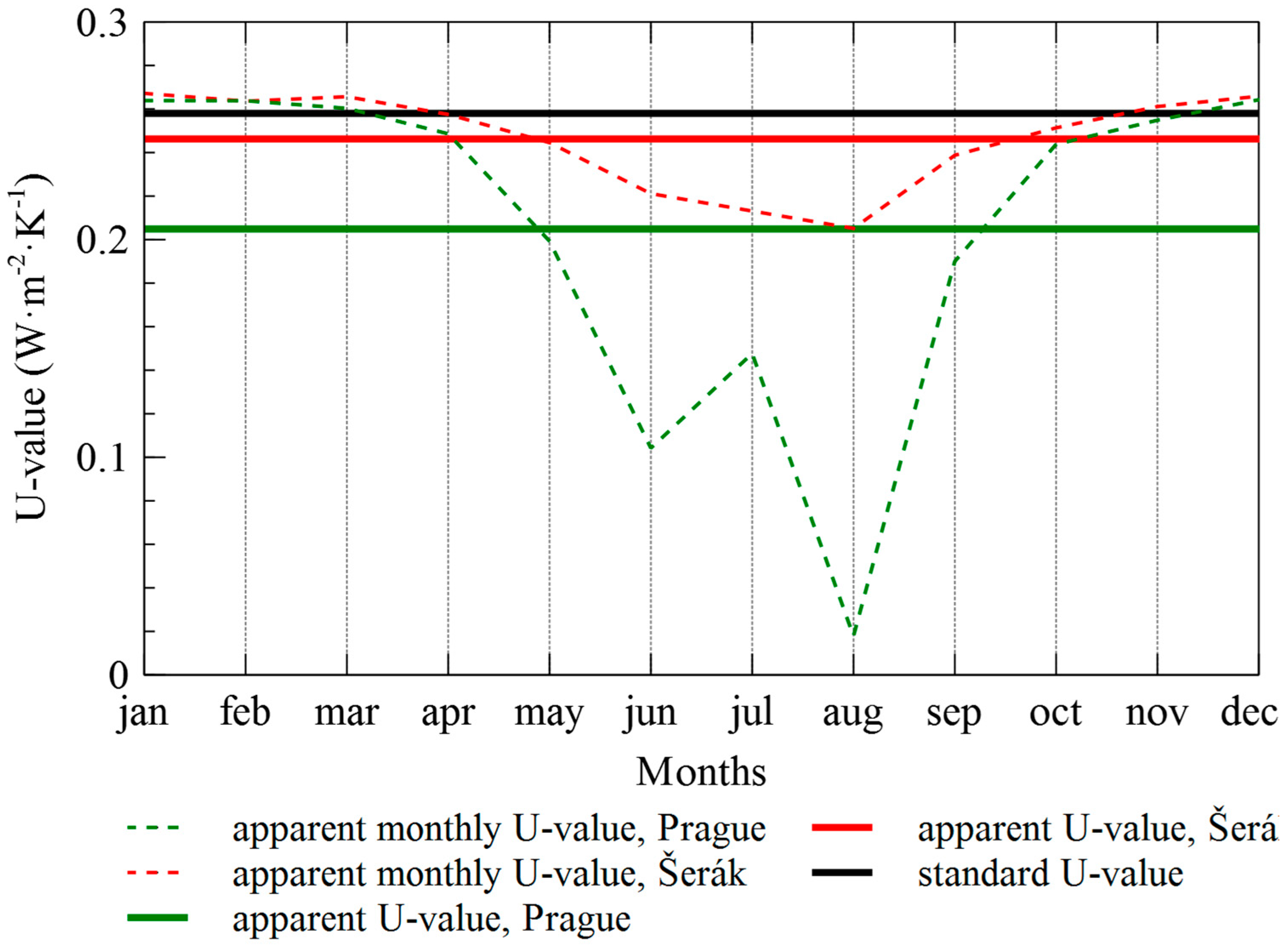
where di (m) is the thickness of individual layer in the composition of wall assembly and λi (W·m−1·K−1) is the thermal conductivity of the material involved in that layer. The U-value for building envelope 1 calculated according to (10) is equal to 0.258 W·m−2·K−1. The apparent value calculated from (9) using (7) and data from Table 6, Tables S1 and S2 is equal to 0.205 W·m−2·K−1 for Prague and 0.246 W·m−2·K−1 for Šerák. Although the standard U-value is on the safe side in this case, as it claims higher (i.e., worse) U-value than the apparent U-value approach, when individual months are analyzed in detail, it can be different in some other cases. Looking at Figure 4 showing apparent U-values during individual months, it is obvious that the construction will not meet the criteria given by standards during winter periods. The brick wall located in Prague will not stand the comparison in months December to March, while the same wall located in Šerák will not meet the criteria from November to March.
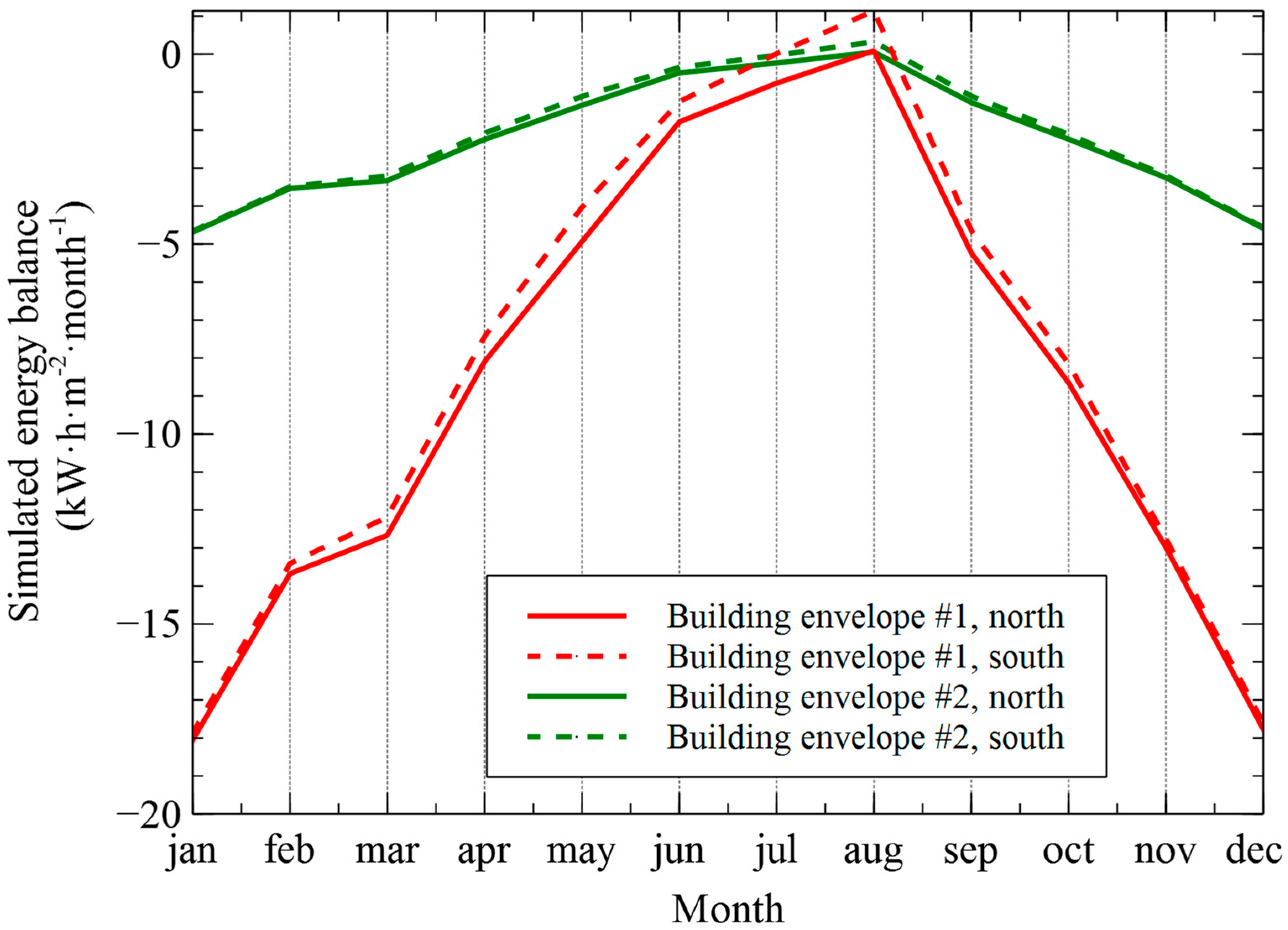
The analysis of solar radiation and precipitation and wall orientation was performed on wall assemblies made of ceramic brick both insulated and non-insulated (building envelopes 1 and 2). For that analysis, a location of Velké Meziříčí (location 37) was selected. The monthly heat fluxes for different wall orientations are depicted in Figure 5.
The highest differences in simulated energy balances can be observed during summer period especially when non-insulated walls (building envelope #2) are considered. The differences in non-insulated walls (building envelope #1) range from 0.55% in winter (December) to more than 100% in summer (July). In absolute numbers, the differences are up to 1.050 kW·h·m−2·month−1 (August). The differences in case of insulated brick wall are significantly less when speaking of absolute numbers. The highest difference in heat fluxes of north and south orientation can be observed in the same month of August, but the difference is only 0.269 kW·h·m−2·month−1, which is given by the insulation capability of expanded polystyrene. Such inaccuracies should be considered when using this method in the practice.
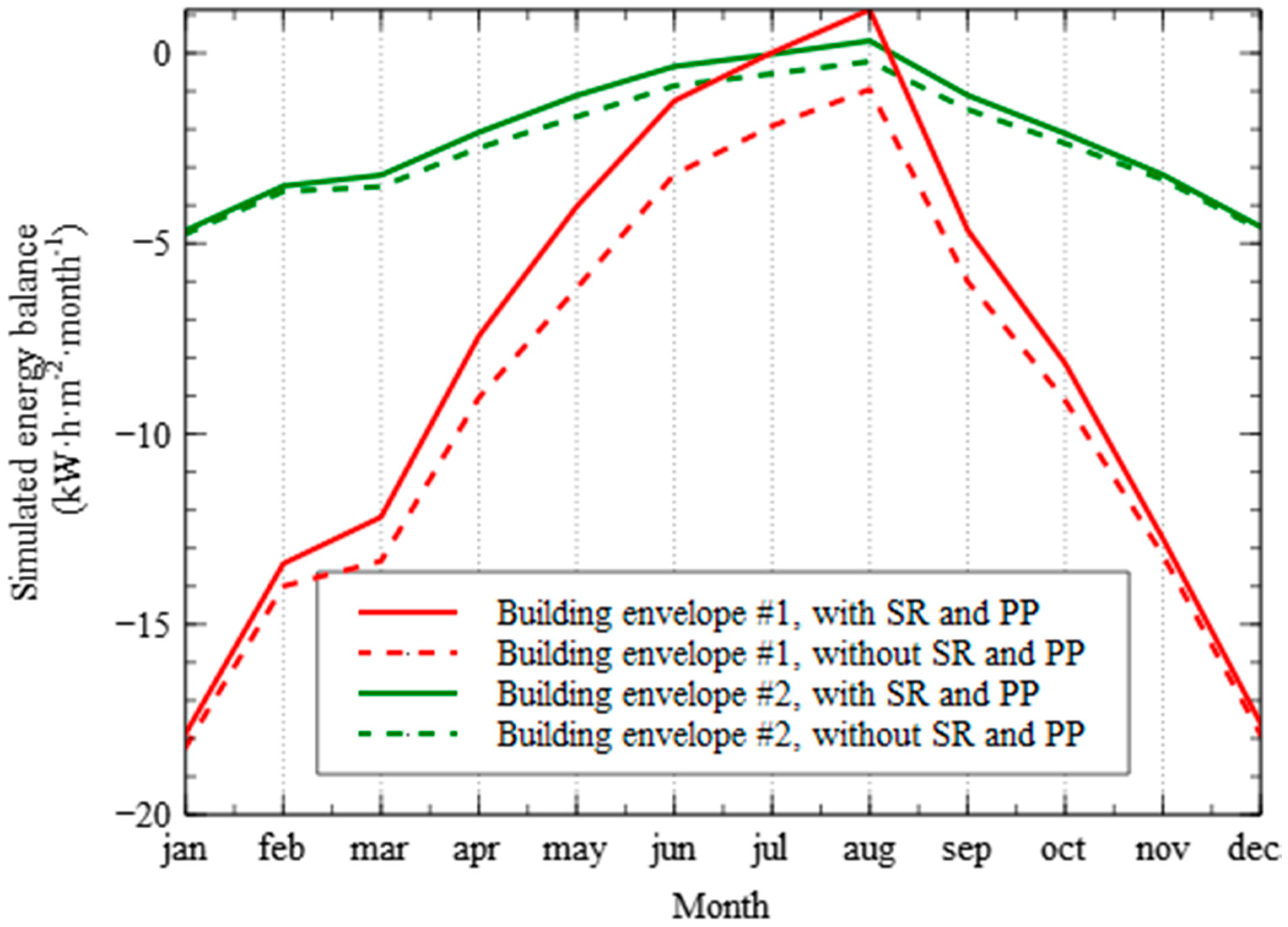
The effect of solar radiation (SR) and precipitation (PP) on monthly heat fluxes is shown in Figure 6. Similarly, to results shown in Figure 4, the highest differences can be observed in case of a non-insulated wall. The effects of solar radiation and precipitation contribute to the overall energy balance by approximately 2% in winter periods, but more significantly in summer. In case of non-insulated wall, the sun radiation can change the overall heat balance from negative to positive, which may be a very significant factor. For that reason, the effects of solar radiation and precipitation should be included in the computational model in order to produce satisfactory results. The fact that the presented method allows for the prediction of thermal performance of wall assembly including the effects of solar radiation and precipitation only from the knowledge of average monthly values temperature and relative humidity together with the elevation makes the method very useful. Since there can be found some level of correlation between temperature and solar radiation, or relative humidity and precipitation, the knowledge of limited weather data could be sufficient to bring relatively accurate predictions.

5. Conclusions

In this study, we introduced a method suitable for rapid evaluation of thermal performance of building walls, which needs only monthly averages of temperature and relative humidity for a given location and its elevation as input data. The proposed approach was successfully tested for nine different types of wall assemblies. The results showed a good accuracy of the method; the average prediction error for tested wall assemblies was ranging between 1.63 and 6.43%.
The proposed approach can be considered as very time-saving, as compared with the methods that involve utilization of robust models. On the other hand, since the effect of moisture content is included in the model outputs, this approach outperforms more simplified models and methods. As a result, it offers a solution, which is neither too simple nor too complex. The presented method can be used for any location across Europe and can also be easily extended to any kind of wall assembly or building envelope component. Since the utilization of the proposed method is demonstrated on nine different wall assemblies only, the method should be extended to a broader range of wall assemblies or building components. In this way, a catalogue or database for civil engineers and designers can be generated, facilitating the thermal design of building structures or fast pre-assessment of wall assemblies from several points of view, e.g. predispositions to frost-induced damage, biofilms growth conditions or salt attack.

Supplementary Materials

The following are available online at https://www.mdpi.com/1996-1073/12/7/1353/s1, Table S1: Average monthly temperature of investigated locations. Table S2: Average monthly relative humidity of investigated locations. Table S3: Average monthly temperatures obtained from Meteonorm database. Table S4: Average monthly relative humidity obtained from Meteonorm database.

Author Contributions

Methodology, J.K.; Resources, J.K.; Software, V.K.; Supervision, R.Č.; Validation: V.K.; Writing–original draft, J.K.; Writing–review & editing, J.K.

Funding

This research was funded by the Czech Science Foundation, grant number 19-01558S.

Conflicts of Interest

The authors declare no conflict of interest.

References

  1. Consumption of Energy. Available online: http://ec.europa.eu/eurostat/statistics-explained/index.php/Consumption_of_energy (accessed on 17 January 2018).
  2. Cansino, J.M.; Pablo-Romero, M.d.P.; Román, R.; Yniguez, R. Promoting renewable energy sources for heating and cooling in EU-27 countries. Energy Policy 2011, 39, 3803–3812. [Google Scholar] [CrossRef]
  3. ČSN 73 0540, Thermal Protection of Buildings—Part 3: Design Value Quantities; Czech Office for Standards, Metrology and Testing: Prague, Czech Republic, 2005.
  4. UNE-EN 673 Glass in Building—Determination of Thermal Transmittance (U Value)—Calculation Method; Deutsches Institut für Normung: Berlin, Germany, 2011.
  5. BS EN ISO 10077-2, Thermal Performance of Windows, Doors and Shutters. Calculation of Thermal Transmittance; Numerical Method for Frames; British Standards Institution: London, UK, 2017.
  6. Caruana, C.; Yousif, C.; Bacher, P.; Buhagiar, S.; Grima, C. Determination of thermal characteristics of standard and improved hollow concrete blocks using different measurement techniques. J. Build. Eng. 2017, 13, 336–346. [Google Scholar] [CrossRef]
  7. EN ISO 8990:1994, Thermal Insulation—Determination of Steady State Thermal Transmission Properties—Calibrated and Guarded Hot Box; International Organization for Standardization: Geneva, Switzerland, 1994.
  8. ASTM C1363-11, Standard Test Method for Thermal Performance of Building Materials and Envelope Assemblies by Means of a Hot Box Apparatus; ASTM International: West Conshohocken, PA, USA, 2011.
  9. ASHRAE Transactions 92, Thermal Resistance Measurements of Well-Insulated and Super Insulated Residential Walls Using a Calibrated Hotbox; ASHRAE Inc.: Atlanta, GA, USA, 1986; pp. 604–619.
  10. Szodrai, F.; Lakatos, A.; Kalmar, F. Analysis of the change of the specific heat loss coefficient of buildings resulted by the variation of the geometry and the moisture load. Energy 2016, 115, 820–829. [Google Scholar] [CrossRef]
  11. Jerman, M.; Černý, R. Effect of moisture content on heat and moisture transport and storage properties of thermal insulation materials. Energy Build. 2012, 53, 39–46. [Google Scholar] [CrossRef]
  12. Khan, M.I. Factors affecting the thermal properties of concrete and applicability of its prediction models. Build. Environ. 2002, 37, 607–614. [Google Scholar] [CrossRef]
  13. Byrne, A.; Byrne, G.; Davies, A.; Robinson, A.J. Transient and quasi-steady thermal behaviour of a building envelope due to retrofitted cavity wall and ceiling insulation. Energy Build. 2013, 61, 356–365. [Google Scholar] [CrossRef] [Green Version]
  14. Marchio, D.; Rabl, A. Energy-efficient gas-heated housing in France: Predicted and observed performance. Energy Build. 1991, 17, 131–139. [Google Scholar] [CrossRef]
  15. Branco, G.; Lachal, B.; Callinelli, P.; Weber, W. Predicted versus observed heat consumption of a low energy multifamily complex in Switzerland based on long-term experimental data. Energy Build. 2004, 36, 543–555. [Google Scholar] [CrossRef]
  16. Roels, S.; Bacher, P.; Bauwens, G.; Castano, S.; Jiménez, M.J.; Madsen, H. On site characterisation of the overall heat loss coefficient: Comparison of different assessment methods by a blind validation exercise on a round robin test box. Energy Build. 2017, 153, 179–189. [Google Scholar] [CrossRef]
  17. Ficco, G.; Iannetta, F.; Ianniello, E.; Romana d’Ambrosio Alfano, F.; Dell’sola, M. U-value in situ measurement for energy diagnosis of existing buildings. Energy Build. 2015, 104, 108–121. [Google Scholar] [CrossRef]
  18. Robinson, A.J.; Lesage, F.J.; Reilly, A.; McGranaghan, G.; Byrne, G.; O’Hegarty, R.; Kinnane, O. A new transient method for determining thermal properties of wall section. Energy Build. 2017, 142, 139–146. [Google Scholar] [CrossRef]
  19. Byrne, A.; Byrne, G.; Robinson, A. Compact facility for testing steady and transient thermal performanceof building walls. Energy Build. 2017, 152, 602–614. [Google Scholar] [CrossRef]
  20. Perilli, S.; Sfarra, S.; Guerrini, M.; Bisegna, F.; Ambrosini, D. The thermophysical behaviour of cork supports doped with an innovative thermal insulation and protective coating: A numerical analysis based on in situ experimental data. Energy Build. 2018, 159, 508–528. [Google Scholar] [CrossRef]
  21. O’Grady, M.; Lechowska, A.A.; Harte, A.M. Quantification of heat losses through building envelope thermal bridges influenced by wind velocity using the outdoor infrared thermography technique. Appl. Energy 2017, 208, 1038–1052. [Google Scholar] [CrossRef]
  22. Olofsson, T.; Andersson, S. Overall heat loss coefficient and domestic energy gain factor for single-family buildings. Build. Environ. 2002, 37, 1019–1026. [Google Scholar] [CrossRef]
  23. Liu, Y.; Harris, D.J. Full-scale measurements of convective coefficient on external surface of a low-rise building in sheltered conditions. Energy Build. 2007, 42, 2718–2736. [Google Scholar] [CrossRef]
  24. Wang, Z.Y.; Srinivasan, R.S.; Shi, J. Artificial Intelligent Models for Improved Prediction of Residential Space Heating. J. Energy Eng. 2016, 142, 04016006. [Google Scholar] [CrossRef]
  25. Meteonorm, Version 6.0, Software Version 6.1.0.20 from April 2010; Meteotest: Bern, Switzerland, 2010.
  26. Bilbao, J.; Miguel, A.; Franco, J.A.; Ayuso, A. Test Reference Year Generation and Evaluation Methods in the Continental Mediterranean Area. J. Appl. Meteorol. 2004, 43, 390–400. [Google Scholar] [CrossRef]
  27. Kalamees, T.; Kurnitski, J. Estonian test reference year for energy calculations. Proc. Estonian Acad. Sci. Eng. 2006, 12, 40–58. [Google Scholar]
  28. Lee, K.; Yoo, H.; Levermore, G.J. Generation of typical weather data using the ISO Test Reference Year (TRY) method for major cities of South Korea. Build. Environ. 2010, 45, 956–963. [Google Scholar] [CrossRef]
  29. Künzel, H.M. Simultaneous Heat and Moisture Transport in Building Components. Ph.D. Thesis, IRB Verlag, Stuttgart, Germany, 1995. [Google Scholar]
  30. Maděra, J.; Kočí, J.; Kočí, V.; Kruis, J. Parallel modelling of hygrothermal performance of external wall made of highly perforated bricks. Adv. Eng. Softw. 2017, 113, 47–53. [Google Scholar] [CrossRef]
  31. Kruis, J.; Koudelka, T.; Krejčí, T. Efficient computer implementation of coupled hydro-thermo-mechanical analysis. Math. Comput. Simul. 2010, 80, 1578–1588. [Google Scholar] [CrossRef]
  32. Kočí, V.; Kočí, J.; Maděra, J.; Pavlík, Z.; Gu, X.; Zhang, W.; Černý, R. Thermal and hygric assessment of an inside-insulated brick wall: 2D critical experiment and computational analysis. J. Build. Phys. 2018, 41, 497–520. [Google Scholar] [CrossRef]
  33. Pavlík, Z.; Fiala, L.; Vejmelková, E.; Černý, R. Application of Effective Media Theory for Determination of Thermal Properties of Hollow Bricks as a Function of Moisture Content. Int. J. Thermophys. 2013, 34, 894–908. [Google Scholar] [CrossRef]
  34. Čáchová, M.; Koňáková, D.; Vejmelková, E.; Keppert, M.; Polozhiy, K.; Černý, R. Pore Structure and Thermal Characteristics of Clay Bricks. Adv. Mater. Res. 2014, 982, 104–107. [Google Scholar] [CrossRef]
  35. Vejmelková, E.; Pavlíková, M.; Keppert, M.; Keršner, Z.; Rovnaníková, P.; Ondráček, M.; Sedlmajer, M.; Černý, R. High performance concrete with Czech metakaolin: Experimental analysis of strength, toughness and durability characteristics. Constr. Build. Mater. 2010, 24, 1404–1411. [Google Scholar] [CrossRef]
  36. Kočí, V.; Maděra, J.; Fořt, J.; Žumár, J.; Pavlíková, M.; Pavlík, Z.; Černý, R. Service Life Assessment of Historical Building Envelopes Constructed Using Different Types of Sandstone: A computational Analysis Based on Experimental Input Data. Sci. World J. 2014, 2014, 802509. [Google Scholar] [CrossRef]
  37. Jiřičková, M.; Černý, R. Effect of hydrophilic admixtures on moisture and heat transport and storage parameters of mineral wool. Constr. Build. Mater. 2006, 20, 425–434. [Google Scholar] [CrossRef]
  38. Kočí, V.; Maděra, J.; Jerman, M.; Žumár, J.; Koňáková, D.; Čáchová, M.; Vejmelková, E.; Reiterman, P.; Černý, R. Application of waste ceramic dust as a ready-to-use replacement of cement in lime-cement plasters: An environmental-friendly and energy-efficient solution. Clean Technol. Environ. Policy 2016, 18, 1725–1733. [Google Scholar] [CrossRef]
  39. Vejmelková, E.; Keppert, M.; Keršner, Z.; Rovnaníková, P.; Černý, R. Mechanical, fracture-mechanical, hydric, thermal, and durability properties of lime-metakaolin plasters for renovation of historical buildings. Constr. Build. Mater. 2012, 31, 22–28. [Google Scholar] [CrossRef]
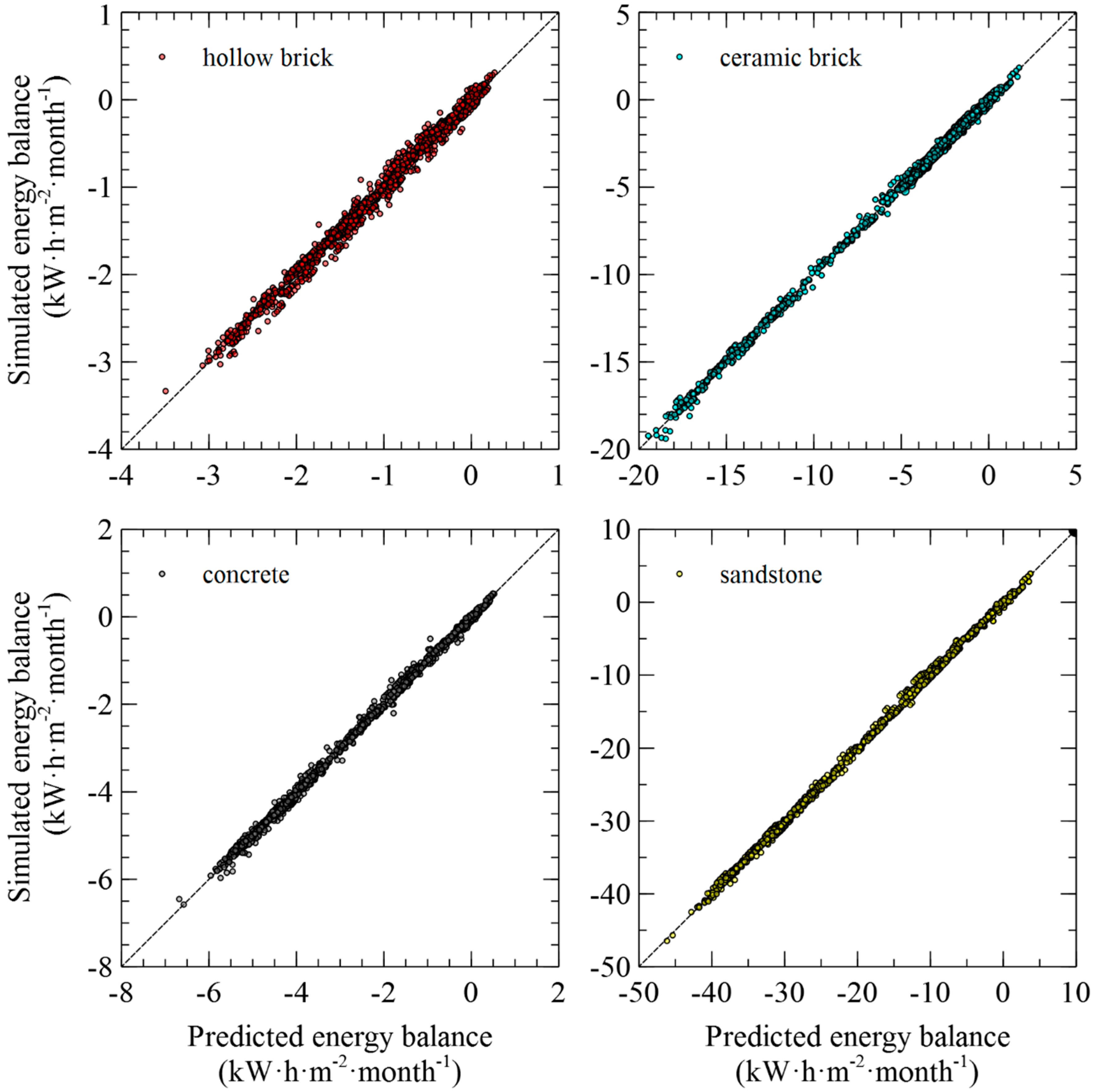
Figure 1. Training phase of the identification procedure.
Energies 12 01353 g001
Figure 2. Testing phase of the identification procedure.
Energies 12 01353 g002
Figure 3. Verification using Meteonorm data.
Energies 12 01353 g003
Figure 4. Comparison of standard and apparent U-values for brick masonry.
Energies 12 01353 g004
Figure 5. Comparison of monthly heat fluxes on interior surface of brick wall with different orientations.
Energies 12 01353 g005
Figure 6. Analysis of the effect of solar radiation (SR) and precipitation (PP) on the simulated energy balance of south oriented walls.
Energies 12 01353 g006
Table 1. List of applied weather data.
Location (Elevation)Location (Elevation)Location (Elevation)
1 Bělotín (306 m)23 Pec p. Sněžkou (816 m)45 Kocelovice (519 m)
2 Bílá Třemošná (322 m)24 Praha–Karlov (261 m)46 Kuchařovice (334 m)
3 Brod nad Dyjí (177 m)25 Přerov (210 m)47 Liberec (398 m)
4 Čáslav (238 m)26 Přimda (743 m)48 Luka (510 m)
5 Červená (748 m)27 Smolenice (345 m)49 Lysá Hora (1322 m)
6 České Budějovice (394 m)28 Stříbro (412 m)50 Ostrava (253 m)
7 Doksany (158 m)29 Šerák (1328 m)51 Praha–Ruzyně (364 m)
8 Domažlice (458 m)30 Svratouch (734 m)52 Přibyslav (533 m)
9 Dukovany (400 m)31 Tábor (459 m)53 Ústí n. Labem (375 m)
10 Harrachov (675 m)32 Temelín (500 m)54 Horní Bečva (565 m)
11 Heřmanův Městec (275 m)33 Tuhaň (160 m)55 Úpice (413 m)
12 Holenice (432 m)34 Tušimice (322 m)56 Šumperk (328 m)
13 Holešov (222 m)35 Ústí nad Orlicí (402 m)57 Krušovice (379 m)
14 Cheb (483 m)36 Val. Klobouky (160 m)58 Mladá Boleslav (221 m)
15 Ivanovice na Hané (243 m)37 Velké Meziříčí (452 m)59 Filipova Huť (1110 m)
16 Jindřichův Hradec (524 m)38 Vír (473 m)60 Bečov n. Teplou (535 m)
17 Košetice (534 m)39 Zbiroh (476 m)61 Hustopeče (201 m)
18 Kostelní Myslová (569 m)40 Železná Ruda (866 m)62 Kestřany (381 m)
19 Měděnec (828 m)41 Brno–Tuřany (241 m)63 Slaný (307 m)
20 Most (240 m)42 Hradec Králové (230 m)64 Město Albrechtice (498 m)
21 Nepomuk (471 m)43 Churáňov (866 m)
22 Olomouc (215 m)44 Karlovy Vary (603 m)
Table 2. List of studied building enclosures. LC: Lime-cement plaster; LPC: advanced hollow bricks; RPHM: renovation plaster for historical masonry.
Building Env. Load-Bearing MaterialThermal Insulation (100 mm)Plaster (10 mm)
1Ceramic brick (450 mm)N/ALC plaster
2Ceramic brick (450 mm)Expanded polystyreneLC plaster
3Ceramic brick (450 mm)Mineral woolLC plaster
4Concrete (300 mm)Expanded polystyreneLC plaster
5Concrete (300 mm)Mineral woolLC plaster
6Advanced hollow brick (500 mm)N/ALPC plaster
7Advanced hollow brick (500 mm)Expanded polystyreneLPC plaster
8Sandstone (800 mm)N/AN/A
9Sandstone (800 mm)N/ARPHM
Table 3. Basic physical, thermal, and hygric properties of load-bearing materials. C: concrete; CB: ceramic brick; AHB: advanced hollow bricks; S: sandstone.
Material ParameterAHBCBCS
ρv (kg·m−3)1389183123802191
ρmat (kg·m−3)2830258127152668
ψ (%)50.927.912.317.9
λ (W·m−1·K−1)0.0840.591.662.77
c (J·kg−1·K−1)1052825672628
μdry-cup (–)12.822.115.811.6
Table 4. Basic physical, thermal, and hygric properties of thermal insulating and coating materials. MW: mineral wool (MW) and EPS: expanded polystyrene.
Material ParameterMWEPSLCLPCRPHM
ρv (kg·m−3)7016.5124417131637
ρmat (kg·m−3)22601020248026582478
ψ (%)96.998.449.835.633.9
λ (W·m−1·K−1)0.3560.0370.300.6690.664
c (J·kg−1·K−1)81015701054831922
μ (–)2.6258.007.5227.2623.6
Table 5. List of sources of input parameters for computational simulation.
MaterialReference
Advanced hollow brick[33]
Ceramic brick[34]
Concrete[35]
Sandstone[36]
Mineral wool[37]
Expanded polystyrene[11]
Lime-cement plaster[38]
Lime-pozzolan plaster[38]
Renovation plaster for historical masonry[39]
Table 6. Identified correlation coefficients.
BE#c0c1c2c3% ErrorR2
1−14144.67809.76−16.210.23732.040.9985
2−4333.37215.393.610.07163.270.9962
3−4232.08212.143.62−0.01263.870.9948
4−4921.03251.871.850.08301.700.9990
5−5538.32254.0410.810.01312.850.9968
6−2929.06133.685.680.03344.570.9926
7−2367.7294.088.340.00406.430.9852
8−31272.491782.25−35.560.75381.630.9991
9−30679.901747.26−33.680.59701.690.9990