Article

Experimental Investigation of Power Signatures for Cavitation and Water Hammer in an Industrial Parallel Pumping System

by
V.K. Arun Shankar
1,
Umashankar Subramaniam
2,
Sanjeevikumar Padmanaban
3,*,
Jens Bo Holm-Nielsen
3,
Frede Blaabjerg
4 and
S. Paramasivam
5
1
Department of Energy and Power Electronics, School of Electrical Engineering, VIT University, Vellore 632014, India
2
Renewable Energy Lab, College of Engineering, Prince Sultan University, Riyadh 12435, Saudi Arabia
3
Center for Bioenergy and Green Engineering, Department of Energy Technology, Aalborg University, 6700 Esbjerg, Denmark
4
Center of Reliable Power Electronics (CORPE), Department of Energy Technology, Aalborg University, 9220 Esbjerg, Denmark
5
Power Electronics and Drives—Research & Development, Danfoss A/S Drives, Chennai 602105, India
*
Author to whom correspondence should be addressed.
Energies 2019, 12(7), 1351; https://doi.org/10.3390/en12071351
Submission received: 3 March 2019 / Revised: 1 April 2019 / Accepted: 2 April 2019 / Published: 8 April 2019
(This article belongs to the Special Issue Fault Diagnosis in Electric Motors)

Abstract

:
Among the total energy consumption by utilities, pumping systems contribute 30%. It is evident that a tremendous energy saving potential is achievable by improving the energy efficiency and reducing faults in the pumping system. Thus, optimal operation of centrifugal pumps throughout the operating region is desired for improved energy efficiency and extended lifetime of the pumping system. The major harmful operations in centrifugal pumps include cavitation and water hammering. The pump faults are simulated in a real-time experimental setup and the operating point of the pump is estimated correspondingly. In this article, the experimental power quality and vibration measurements of cascade pumps during cavitation and water hammering is recorded for different operating conditions. The results are compared with the normal operating conditions of the pumping system for fault prediction and parameter estimation in a cascade water pumping system. Moreover, the Fast Fourier Transform (FFT) analysis comparison of normal and water hammering (faulty condition) highlights the frequency response of the pumping system. Also, the various power quality issues, i.e., voltage, current, total harmonic distortion, power factor, and active, reactive, and apparent power for a cascade multipump control is discussed in this article. The vibration, FFT, and various power quality measurements serve as input data for the classification of faulty pump operating condition in contrast with the normal operation of pumping system.

1. Introduction

Energy remains the fundamental requirement for the industrial and residential sectors [1]. Global energy consumption is expected to have an alarming growth by 2030, shown in Figure 1. Among them, the pumping system (especially centrifugal pumps) contributes the major electric loads installed around the globe, contributing ~22% [2]. This is due to the huge availability of energy savings opportunities and various research outcomes suggested for increasing energy efficient pumping system [3]. A review of various energy efficient enhancement centrifugal pumping systems concludes the maximum savings of approximately 5% to 50% can be achieved. This expectation can be made possible by introducing variable frequency drives with proper control methods [4].
Due to the inevitable usage of pumps [5], the supervision on the reliability and fault occurrence of the pumping system is highly significant. The major components of a pumping system consist of a pumping liquid, pump unit, piping, suction, and the delivery setup. The major faults include cavitation and water hammering caused due to the inefficient operation of pumps and piping arrangements in a pumping system. The commercial and industrial loads insist enhancement of energy efficiency [6,7] that leads to the drastically increased usage of Variable Frequency Drives (VFDs) for pumping applications. It reduces the energy consumption along with the regulation of variable flow rate demand of the pumping system [8,9]. Conversely, current/voltage harmonic distortions are generated by installing such nonlinear loads (VFDs).
VFDs are preferred for centrifugal pumps to enhance energy efficiency and reduce the occurrence of faults. Fault diagnosis at an early stage is identified by using vibration-based investigation methods [10,11]. The transient impulse of the motor bearings and rotor faults are diagnosed using wavelet transform (WT) techniques [12]. The signal-based techniques exhibit better performance than the model-based techniques for estimating faults [13,14]. Advanced learning techniques involve developing algorithms that enable the drives to learn, classify between the given categories [15,16], and predict the future states [17,18]. Detection of pump faults like cavitation can be performed by using pump acoustics [5]. The nature of individual power quality parameters varies with the change in pressure, the severity of fault, and the region of operation [19,20,21]. The existing fault detection techniques involve the usage of pump parameters like flow rate and pressure to determine the occurrence of pump cavitation and water hammering; this requires additional sensors. To overcome the shortcomings of the currently available research, the experimental investigation of power quality parameters was proposed to estimate the cavitation and water hammering in a centrifugal pumping system. The change in such power quality parameters, vibration details of normal operation, and simulated fault conditions are recorded as the testing inputs for validating the performance of the study.
In this research, the effectiveness of the fault identification is performed through experimental power quality measurements in a parallel pumping system. Estimating pump defects at an early stage will help perform suitable primitive measures and significantly increase the life of the system. The cascade setup is subjected to various pressure set points, the delivery valve is maintained in a partially closed position, and the response is observed for various set pressure values. The power quality variations are voltage, current, respective Total Harmonic Distortion (THDs), power, power factor, and energy. The power quality variations were observed and recorded for the equidistant set pressure values. Also, the best operating region, in terms of energy efficiency, is suggested using the power quality results. The vibration signal and power quality measurement from the pump is used to estimate and classify faults automatically. The training data is obtained by varying the pressure from 0.1 to 0.5 bar. Also, the cascade pumping system is experimented and validated, in terms of power quality and the efficiency for set pressure, with using observed results.
The article is organized as follows. Firstly, in Section 2, the industrial cascade pumping experimental setup and modeling equations and curves are discussed. In Section 3, the power quality and pump vibration results are presented for a cascade pumping system during normal and abnormal conditions for fault identifications in the cascade pumping system. In Section 4, the experimental vibration, FFT, and power quality signatures are highlighted for cavitation and water hammering. Moreover, the results portraits the significant variation in the power quality and vibration parameters for normal and abnormal pump operating region. It is followed by the conclusion in Section 5.

2. The Cascade Pumping System

Cascade pumping comprises a system with more than one pump that is turned ON/OFF in sequential order to achieve the process set value. In the cascade pumping arrangement, at least one pump is controlled through VFD; whereas other pumps are switched ON through relays with a command from VFDs. The flow rate is the process variable in most of the pumping system. Conventionally, the desired flow rate is achieved by throttling the control valve that shifts the system curve towards left/right over the pump performance curve. Whereas when VFDs are used to change the speed of the motor–pump setup, and the pump performance curves shift along the vertical axis, causing the change in operating point leading to performance variation. Thus, head and the flow rate developed by the pump vary in both the cases. The energy consumed in the latter is comparatively less and the life of the pumping system also increases considerably.

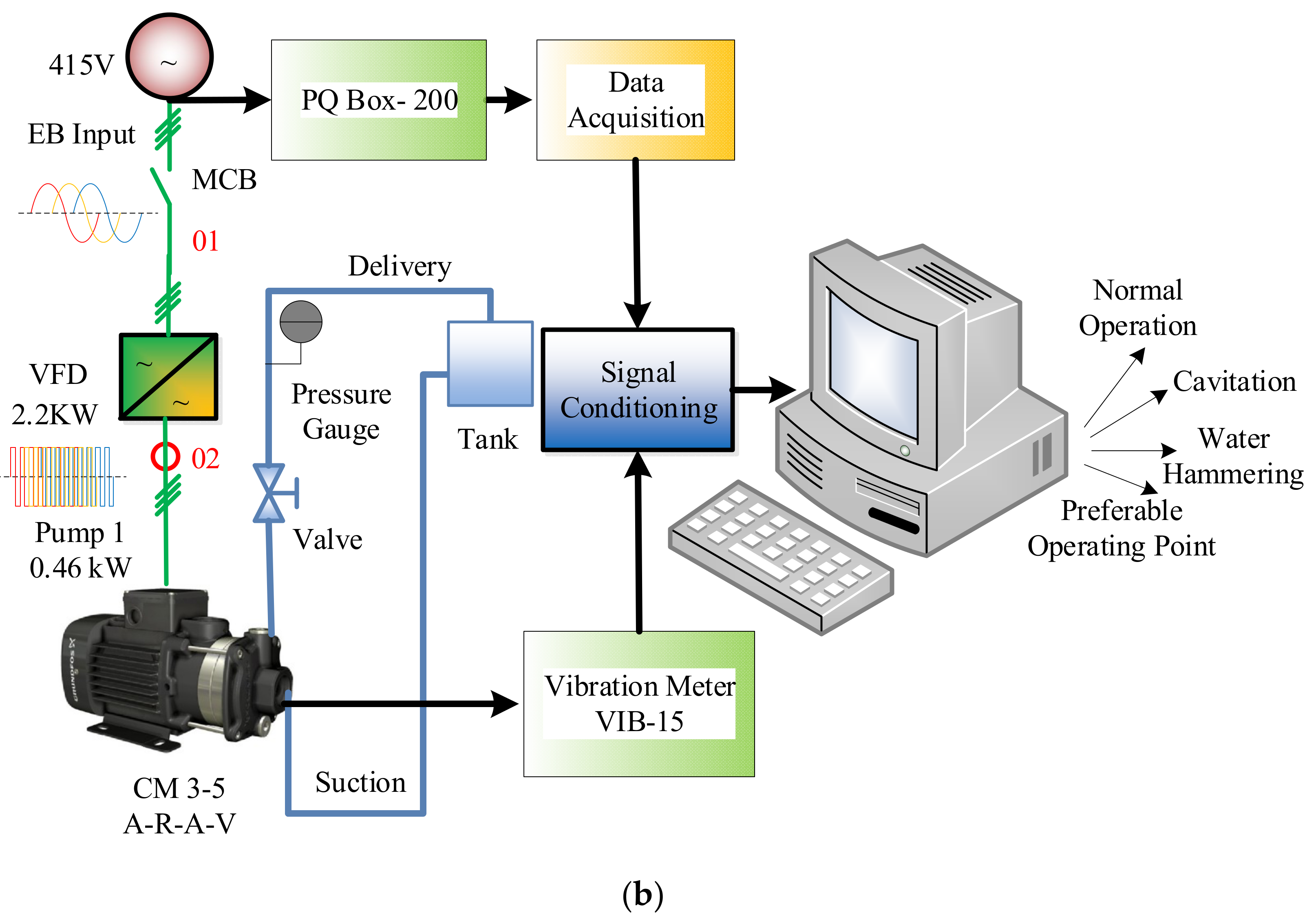
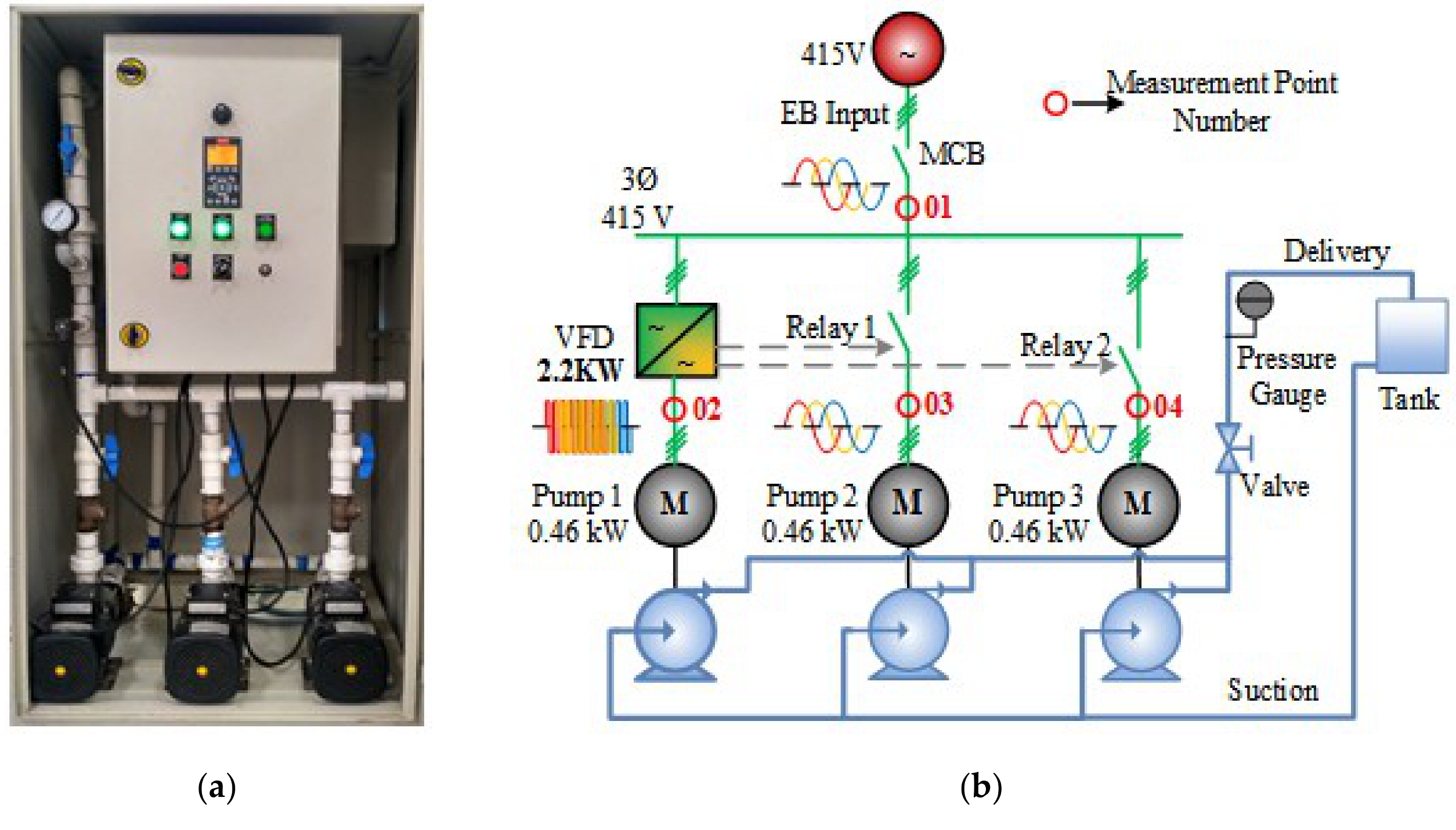
2.1. System Description

The experimental setup of the research consists of three pumps, controlled through VFD and relays as shown in Figure 2. The lead motor–pump unit is connected through VFD and it is referred to as pump 1. The cascade parallel pumping setup is connected to three-phase power source supplying 415 volts at 50 Hz frequency. Figure 2b shows the simplified electrical layout and the laboratory prototype designed for the power quality measurements. To analyze and record the power quality values of a cascade pumping setup, measurements were taken at the point of common coupling (PCC) using a power quality instrument (PQ Box-200). The PQ Box-200 is a class-A instrument is capable of monitoring and recording three-phase power quantities and computing until the 50th harmonic order. The experiment is conducted by varying the pressure set points from 0.1 bar to 0.5 bar, with the valve in open condition. All power quality measurements on the experimental setup were taken at nominal room temperature. The design specification of the experimental setup tested is given in Table 1.

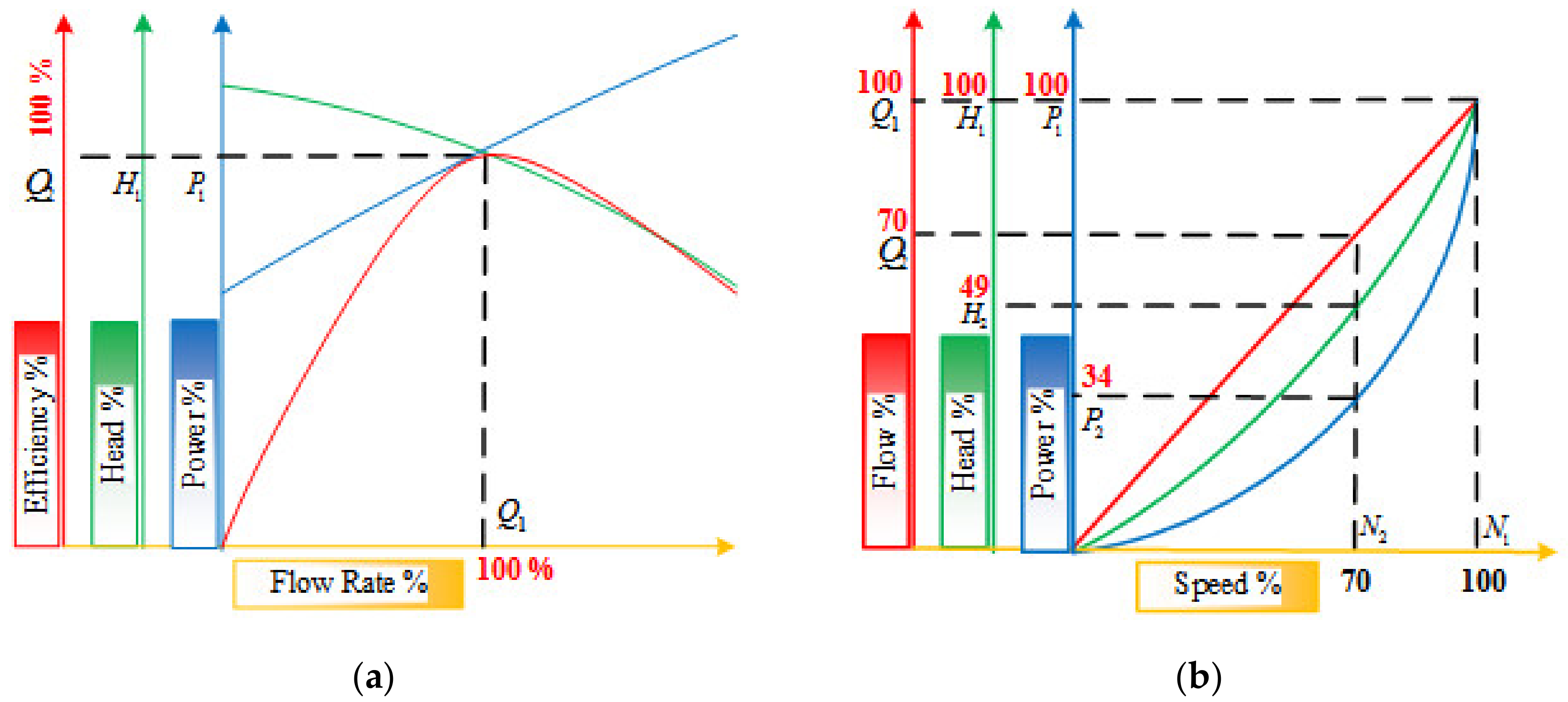
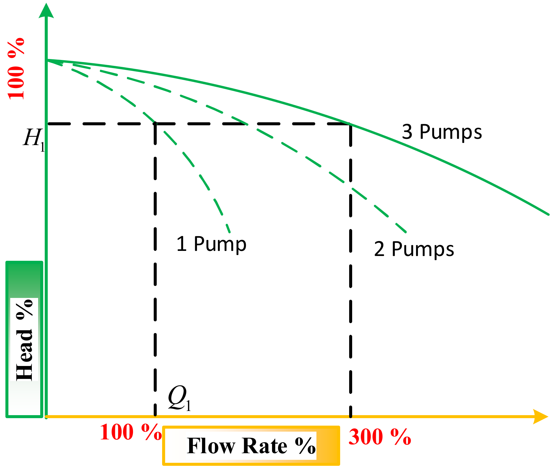
2.2. Pumping System Modeling

The relation between the head developed and the flow rate at specific speed is given by the pump performance curve, as shown in Figure 3. It is the amount of pressure that a pump can develop at given speed, with the change in flow rate. For the given speed, the pump manufacturer also provides efficiency and power drawn for various flow rates in the performance curve [22]. The resistance offered due to the pipes, bends, and valves in a pumping system is expressed as a system curve that incorporates both static and frictional losses. In the case of the closed hydraulic system, only a frictional head is present; the open-loop hydraulic system has both static and frictional heads. The intersection point between the pump performance curve and the system curve is the operating point of the pumping system. It determines the output head (H) and flow rate (Q) developed by the pumping system. The head developed by the centrifugal pump at the delivery side is given by
H = Δ p ρ g = p o p i ρ g
The system curve represents the relation between the water pumped for the head to overcome and the flow rate developed in the pumping system. The static and dynamic head together are known as the system head, and are shown in Equation (2) [23].
H s y s = H s t + H d y n
H s t = c o n s t ,   H d y n = k Q 2
If the hydraulic system transfers the liquid from suction to the delivery, then it is called an open-loop system. In open-loop pumping systems, the dynamic head is a function of the flow rate, and the static head remains unchanged (as in Equation (3)). The static head is zero for a closed loop pumping system [24] (as in Equation (4)).
H s y s = H d y n ,   H s t = 0
Affinity laws exhibited by centrifugal pumps state the relation between the pump parameters like rate of flow, head developed, and power drawn with respect to change in rotational speed (see Equation (5)).
Q 1 Q 2 = N 1 N 2 ,   H 1 H 2 = N 1 N 2 2 ,   P 1 P 2 = N 1 N 2 3
where suffixes 1 and 2 represent previous values and estimated values, respectively. The pump performance curve has the QH curve of individual pumps with the system curve. Also, the resultant QH curve of the three pumps provides the maximum operating range of the pumping system, as shown in Figure 4. The system operating point is obtained from the intersection of the resultant pump curve and the system curve. From the system operating point, an individual pump’s flow rate and head developed values can be attained. The system curve and the QH curve of the fixed speed pumps remain unchanged for different set pressures. As pump 1 is operated through VFD, the QH curve varies with the change in operating speed of the pump. Thus, the pump operating point can be estimated from the pump performance curves.

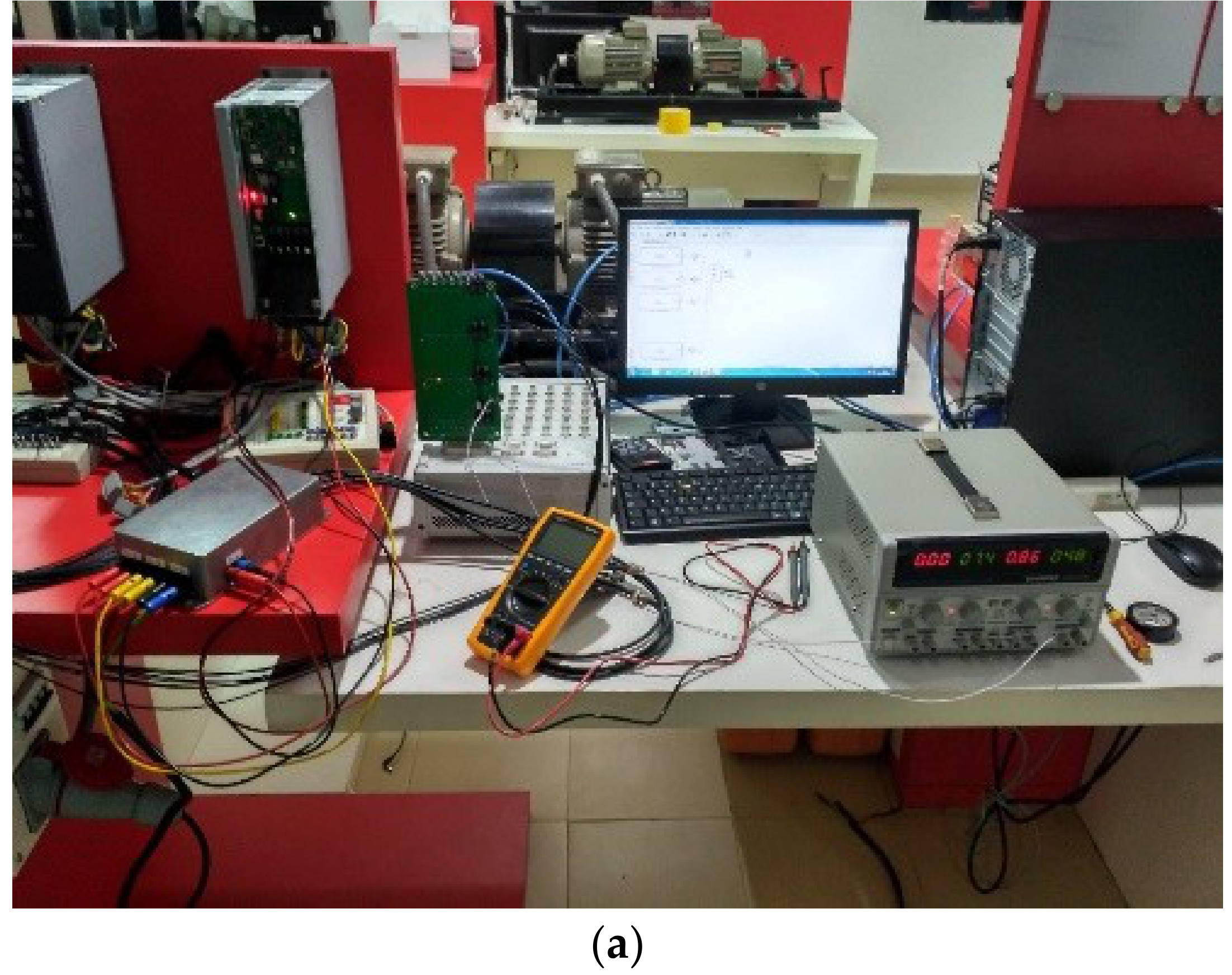
3. Experimental Test with Cascaded Industrial Variable Frequency Drives Pumping System

The experimental results of motor parameters for the pressure set points of 0.1, 0.3, and 0.5 bar were recorded through the hardware interfacing platform (dSPACE and MCT 10), as shown in Figure 5. Significant motor control parameters like speed, motor current, set reference, voltage, frequency, power drawn, and feedback (actual pressure) were monitored and recorded. From the waveform, variable speed pump (pump 1) is initiated at the beginning of the process. Since pump 1 alone is unable to deliver the required set pressure (0.3 bar), an additional pump (pump 2) is staged on to run at the rated speed. However, pump 1 starts from the minimum speed limit, and accelerates gradually to reach the pressure set point.
The valve positions can be kept either at fully or partially open condition. In the study, the valve position is maintained in the partially opened condition, and the rated voltage is applied across the point of common coupling (PCC). The experimentation is performed by taking five equidistant pressure set points: 0.1, 0.2, 0.3, 0.4, and 0.5 bar. The pressure gauge reading is monitored by the internal cascade control algorithm as it tries to reach the pressure set point. It is accomplished by varying the speed of the pump 1 and turning ON/OFF pump 2 and pump 3. For waveform analysis purpose three pressure levels—0.1, 0.3, and 0.5 bar—are considered. The operational state (ON/OFF) of the motor–pump is defined in Table 2. Pump 1 alone operates at a lower pressure set point of 0.1 bar, and pumps are added into operation when the pressure set point increases.
When the available net positive suction head value (NPSHA) is lower than the required net positive suction head value (NPSHR) the centrifugal pump exhibits cavitation. The NPSHR was provided by the pump manufacturer, and the NPSHA is calculated from pump system parameters like friction loss, atmospheric pressure, and static head. The water hammering occurs whenever there is a sudden increase in pressure change, i.e., sudden closure/opening of valves that causes severe damage to the pipes. To realize water hammering in the real-time experimental setup, electric valve actuators in the delivery side were used. These electronic controlled valves have a much smaller time constant for the sudden closure of the valve and opening at the same to induce water hammering in the pumping system. In this research we have not considered the fault condition with both water hammering and cavitation at the same instant, and the vibration measurement details are provided to confirm that the pump and piping systems are operated safely when realizing water hammering.

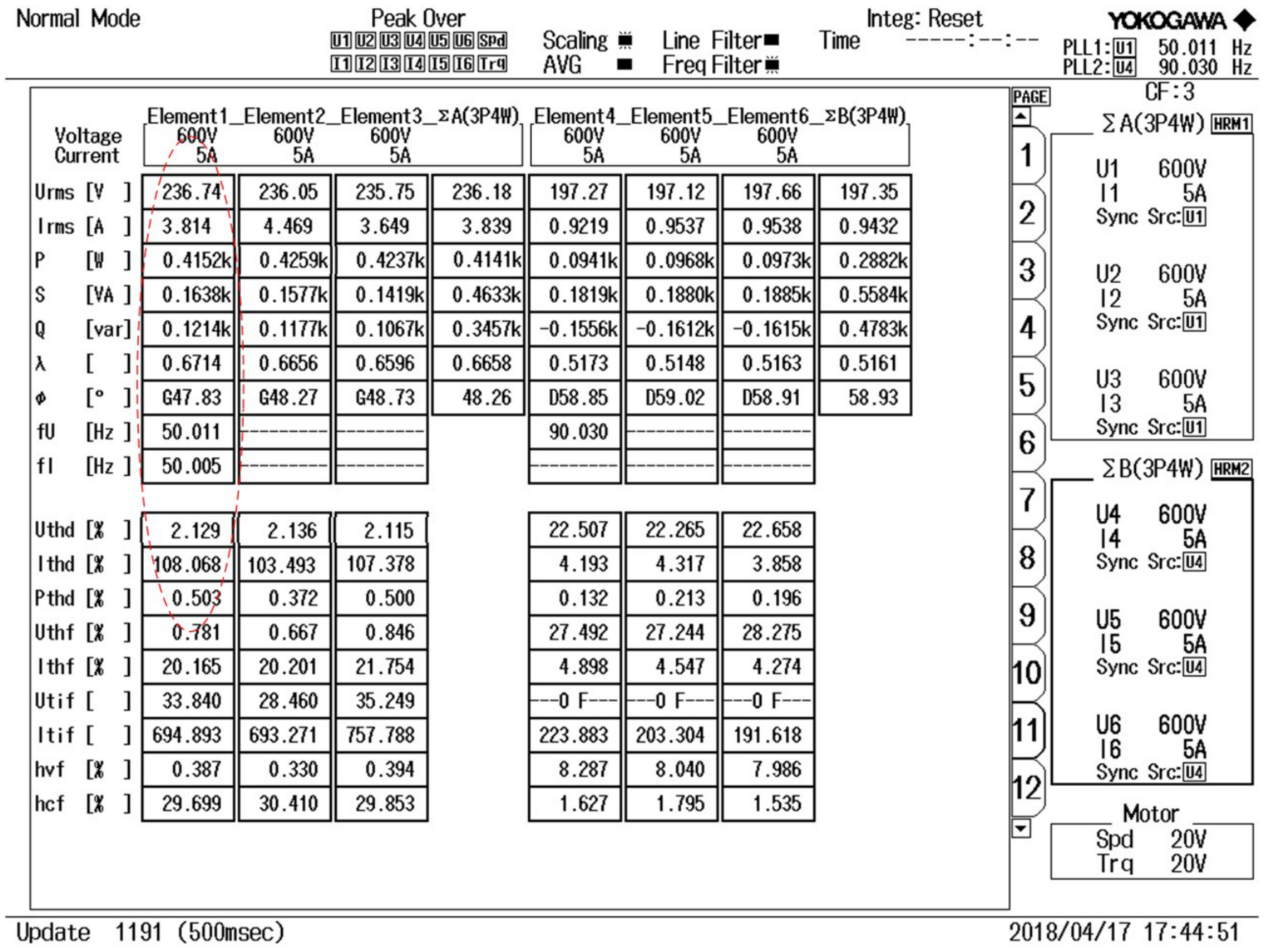
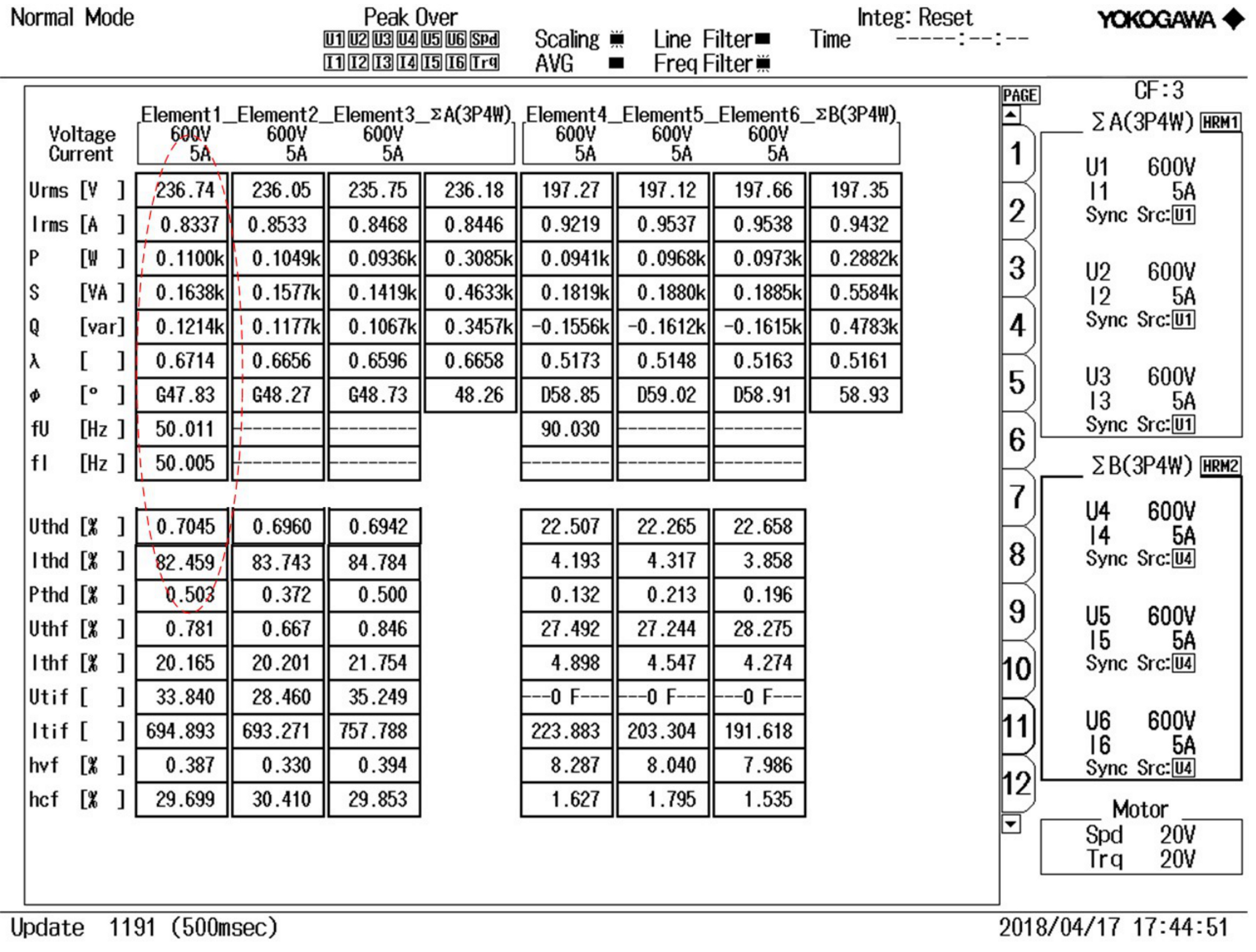
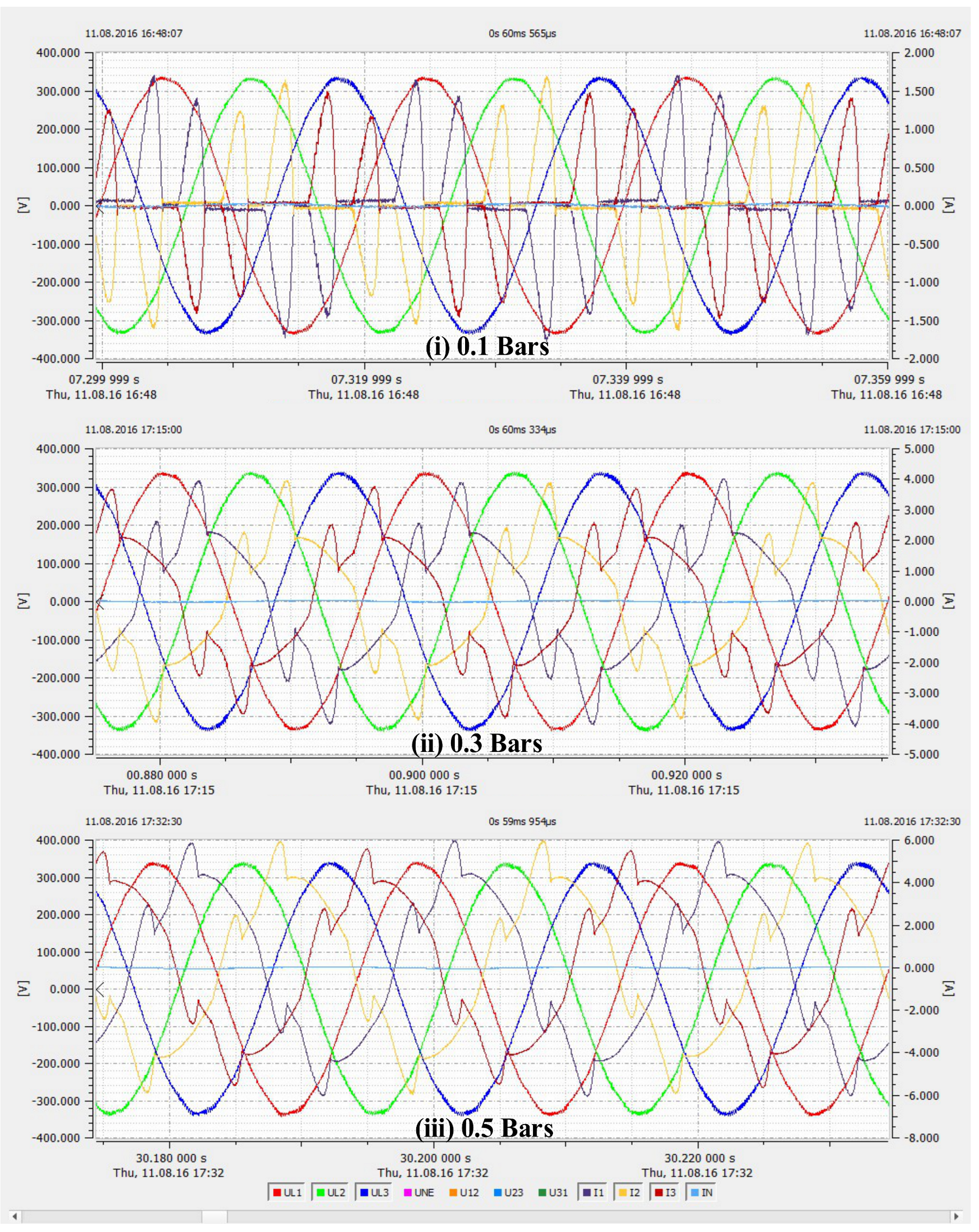
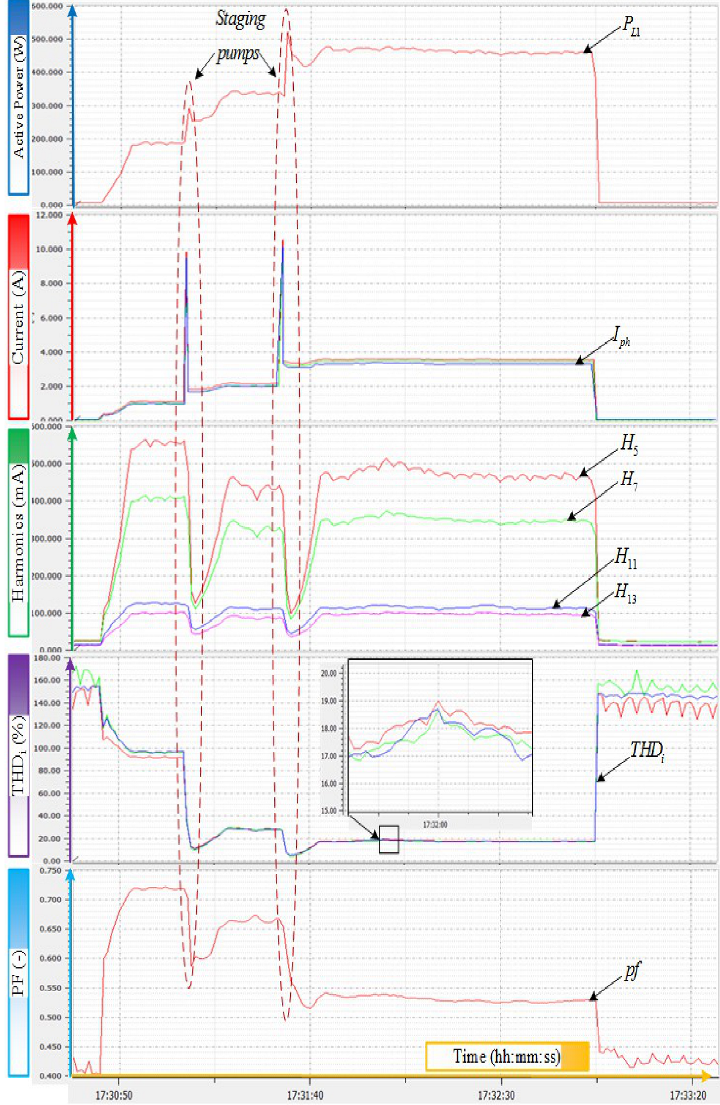
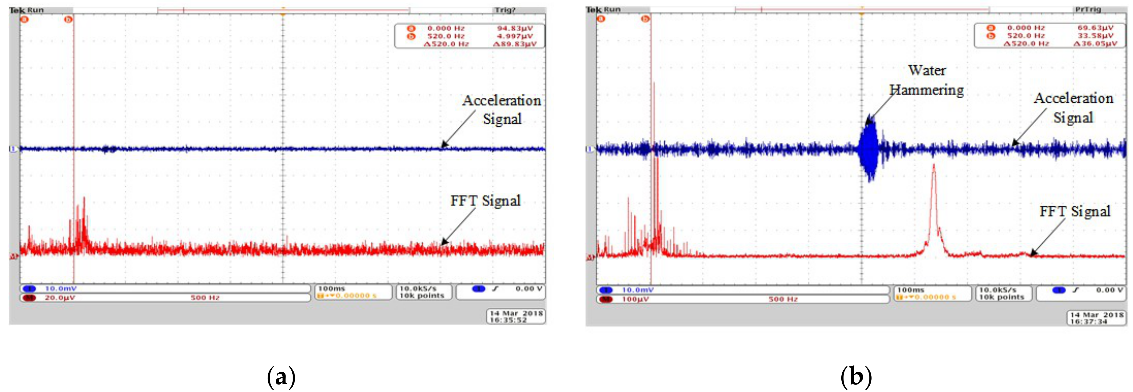
4. Experimental Power Quality Signatures

The effectiveness of the proposed methodology is calibrated by testing a practical industrial pumping setup with variable speed drives. The results and inference obtained for various operating pressure are plotted for estimating the pumping parameters. Power quality is the capability of electrical equipment to operate in the preferred region without influencing the operation of adjacent equipment connected to the common electrical bus. As the pumps in industry are put into service, the variations in loading/demand cause voltage fluctuations. Hence, for various pressure values (0.1, 0.3, and 0.5 bar) the instantaneous measure of three-phase voltage and current has been observed through WinPQ software (PQBox-200), as shown in Figure 6. The power drawn by the pump driven by VFD is at its maximum when it is operated at a low-pressure set point (say 0.1 bar). When other pumps are staged at higher set pressure (for 0.3 bar) the contribution due to variable speed pump (pump 1) is lower. The contribution of pump 1 still reduces when the pressure set point is further increased to a higher value, i.e., 0.5 bar (see Table 3).
When the primary VFD-operated pump is not sufficient to produce the required set pressure additional pumps are turned ON, with the VFD-controlled pump put back to its minimum operating speed. During such a transition of pumps, the steady-state voltage value remains unchanged. The total current drawn by the cascade pump setup experiences a spike for a momentary period when the additional pumps are added. The power factor during steady-state conditions reduces when the pressure reference increases from 0.1 bars to 0.5 bar. As the load on the pump increases when the pressure is set to 0.5 bar from 0.1 bar, the energy consumed and power drawn also increase. The power drawn during full load capacity fluctuates less when compared with the power drawn at a pressure at 0.1 bar. The steady-state current THD in Table 4 is found to be reducing desirably as the pressure reference increases. For the pressure set values of 0.1 bar, 0.3 bar, and 0.5 bar the current THDs attained are in the range of 100, 25 to 30, and 10 to 20 percent, respectively. The shape of the current drawn in Figure 6 becomes sinusoidal from nonsinusoidal as the loading of the pumping setup is approached towards its maximum capacity. Thus, when the pumping setup is operated near to its full load capacity, the current THD reduces.
The harmonic spectrum obtained through experimentation shows that the mentioned harmonic orders are having higher magnitudes. Among them, the 5th harmonic remains dominant, as shown in Figure 7. The harmonic orders for the six pulse VFDs (Diode Bridge) are expressed through Equation (6).
nv = kp ± 1 = k6 ± 1
nv = 5, 7, 11, 13, 17, 19,…, where p = 6
The vibration meter (VIB-15) was mounted on the pump impeller casing to acquire the vibration details (i.e., acceleration, velocity, and displacement) of the centrifugal pump. The sensitivity of acceleration, velocity, and displacement for the vibration meter is 0.1 g, 0.2 mm/s, and 10 microns, respectively. The input signals are recorded through a 24-bit analog input channel at a sampling rate of 70 kHz. An FFT analysis of the acceleration signal was performed to attain the time–frequency pattern. The study is performed for various operating points with normal and faulty conditions as shown in Table 5. The vibration and FFT signal of the normal defect-free pump and water hammering is noisy when compared with the normal defect-free pump, as shown in Figure 8.
Various power quality parameters measured for the pressure setpoint of 0.5 bars under normal defect-free condition were recorded as shown in Figure 7. The measurements are repeated 10 times and the average value is taken to ensure recording accuracy. The error tolerance and uncertainty of fault detection are restricted to 5%. The faults are simulated in the real-time pumping setup, and the test data (voltages, currents, pressure, flow rate, and speed) is obtained for different pressure set points. The Root Mean Square (RMS) voltage and current, power drawn, voltage THD, current THD, rotational speed, pressure developed, and flow rate for normal and faulty cases have been recorded. The power signatures for cavitation condition at input side of the drive (Element 1, Element 2, and Element 3) and input of the pump–motor set (Element 4, Element 5, and Element 6) are shown in Figure 9. Similarly, the power signature for water hammering condition is shown in Figure 10. The classification/grouping of test data can be performed among the classes that have various attributes and a target function.
The outline of all the measured power quality readings (minimum, average, and maximum values) for the different pressure set points are provided in Table 6. The seven significant power quality parameters considered for the analysis includes voltage, current, kW, kVar, power factor, voltage, and current THD. The voltage range across the PCC varies from 406 V to 410 V, where voltage deviation from the nominal value is less for higher pressure set points. The voltage drops gradually when the pressure set point is significantly less compared to the rated capacity of the cascade pumping setup. When loading of the pumping setup increases (from 0.1 bar to 0.5 bar), the power drawn by the system increases gradually. Whereas, the power factor of the system is better for the lesser loading conditions (i.e., 0.1 bar) when compared with the rated capacity of the setup.

5. Conclusions

The article discusses the real-time simulation of harmful pump operations (i.e., cavitation and water hammering) of centrifugal pumping systems and compares them with the normal operating conditions. Furthermore, the classification of faults and prediction of preferable pump operating points in a pumping system was performed from the experimental power quality measurements. An industrial parallel pumping system was considered for experimental validation, and the unique power quality signatures obtained for water hammering and cavitation enabled the classification of faults from the normal operating condition. The classification of faults based on the power quality pattern can be applied to the centrifugal pump-based pumping systems. The vibration parameters (such as acceleration, velocity, and displacement) show a significant difference to classify normal pump operation from the faulty conditions.
The extensive experimental study on cascade pumping system reveals that the preferable operating region enhances reliability as well as reducing the occurrence of faults. Further, this article serves as a reference for insight power quality issues in VFD pumping systems and paves the way for sensorless control. Also, the unique power quality signatures obtained from the experimental study could be used for machine-based fault classifications in future works.

Author Contributions

All authors were involved in developing the concept to make the article an error-free technical outcome for the set investigation work.

Funding

No funding was received for this research work.

Acknowledgments

The authors would like to acknowledge the support and technical expertise received from the Renewable Energy Lab, Prince Sultan University, Saudi Arabia and the center for Bioenergy and Green Engineering, Department of Energy Technology, Aalborg University, Esbjerg, Denmark. Also, thanks are given to the Center of Reliable Power Electronics (CORPE) for providing additional technical support that made this publication possible.

Conflicts of Interest

The authors declare no conflicts of interest.

Nomenclature

QFlow rate (m3/h)
PPower input (W)
GGravitational constant
HPump head (m)
NRotational speed of pump (rpm)
FMotor frequency (Hz)
KDynamic head coefficient
TTime (s)
VVolume of liquid (m3)
DPump impeller diameter (mm)
a,bExperimental coefficients
VFDVariable frequency drive
VSDVariable speed drive
Δ p Differential pressure
pPump
vVFD
sys.Pumping system
mMotor
hHydraulic
tTotal value
SSpecific energy
stStatic
dynDynamic
inInput to VFD
in,tTotal input to multiple VFDs
jNumber of pumps connected parallel
oOutlet pressure
iInlet pressure
η Efficiency (%)
ρ Density of the liquid (Kg/m3)

References

  1. Robinson, C.; Dilkina, B.; Hubbs, J.; Zhang, W.; Guhathakurta, S.; Brown, M.A.; Pendyala, R.M. Machine learning approaches for estimating commercial building energy consumption. Appl. Energy 2017, 208, 889–904. [Google Scholar] [CrossRef]
  2. ETSU; CETIM; Reeves DT; NESA; Darmstadt TU. Study on Improving the Energy Efficiency of Pumps. 2001. Available online: http://www.jakob-albertsen.dk/komposit/Darmstadtrapport.pdf (accessed on 3 April 2019).
  3. Wang, Z.; Qian, Z. Effects of concentration and size of silt particles on the performance of a double-suction centrifugal pump. Energy 2017, 123, 36–46. [Google Scholar] [CrossRef]
  4. Shankar, V.K.A.; Umashankar, S.; Paramasivam, S.; Hanigovszki, N. A comprehensive review on energy efficiency enhancement initiatives in centrifugal pumping system. Appl. Energy 2016, 181, 495–513. [Google Scholar] [CrossRef]
  5. Diefenderfer, J.; Arora, V.; Singer, L.E. International Energy Outlook 2016 Liquid Fuels. Doe/Eia-0484; 2016; pp. 202–586. Available online: https://www.eia.gov/outlooks/ieo/pdf/0484 (accessed on 3 April 2019).
  6. Abdelaziz, E.A.; Saidur, R.; Mekhilef, S. A review on energy saving strategies in industrial sector. Renew. Sustain. Energy Rev. 2011, 15, 150–168. [Google Scholar] [CrossRef]
  7. Yildiz, B.; Bilbao, J.I.; Sproul, A.B. A review and analysis of regression and machine learning models on commercial building electricity load forecasting. Renew. Sustain. Energy Rev. 2017, 73, 1104–1122. [Google Scholar] [CrossRef]
  8. Chang, W.; Chang, J.W.; Yin, H.; Wang, W.J.; Chung, H.Y.; Chang, Y.C.; Chen, H.C. Energy-saving algorithm for pumping systems based on fuzzy decision making. In Proceedings of the IEEE International Conference on Systems, Man, and Cybernetics (SMC), Seoul, South Korea, 14–17 October 2012; pp. 2395–400. [Google Scholar] [CrossRef]
  9. Ahonen, T.; Tamminen, J.; Viholainen, J.; Koponen, J. Energy efficiency optimizing speed control method for reservoir pumping applications. Energy Effic. 2014, 8, 117–128. [Google Scholar] [CrossRef]
  10. Ge, Z.; Song, Z.; Ding, S.X.; Huang, B. Data Mining and Analytics in the Process Industry: The Role of Machine Learning. IEEE Access 2017, 5, 20590–20616. [Google Scholar] [CrossRef]
  11. Najafi, M.; Auslander, D.M.; Bartlett, P.L.; Haves, P.; Sohn, M.D. Application of machine learning in the fault diagnostics of air handling units. Appl. Energy 2012, 96, 347–358. [Google Scholar] [CrossRef]
  12. Campana, P.E.; Li, H.; Yan, J. Dynamic modelling of a PV pumping system with special consideration on water demand. Appl. Energy 2013, 112, 635–645. [Google Scholar] [CrossRef]
  13. Wen, L.; Li, X.; Gao, L.; Zhang, Y. A New Convolutional Neural Network-Based Data-Driven Fault Diagnosis Method. IEEE Trans. Ind. Electron. 2018, 65, 5990–5998. [Google Scholar] [CrossRef]
  14. Daut, M.A.M.; Hassan, M.Y.; Abdullah, H.; Rahman, H.A.; Abdullah, M.P.; Hussin, F. Building electrical energy consumption forecasting analysis using conventional and artificial intelligence methods: A review. Renew. Sustain. Energy Rev. 2017, 70, 1108–1118. [Google Scholar] [CrossRef]
  15. Alobaidi, M.H.; Chebana, F.; Meguid, M.A. Robust ensemble learning framework for day-ahead forecasting of household based energy consumption. Appl. Energy 2018, 212, 997–1012. [Google Scholar] [CrossRef]
  16. Zhao, L.; Wang, X. A Deep Feature Optimization Fusion Method for Extracting Bearing Degradation Features. IEEE Access 2018, 6, 19640–19653. [Google Scholar] [CrossRef]
  17. Li, C.; Zhang, W.; Peng, G.; Liu, S. Bearing Fault Diagnosis Using Fully-Connected Winner-Take-All Autoencoder. IEEE Access 2017, 6, 6103–6115. [Google Scholar] [CrossRef]
  18. Fan, C.; Xiao, F.; Zhao, Y. A short-term building cooling load prediction method using deep learning algorithms. Appl. Energy 2017, 195, 222–233. [Google Scholar] [CrossRef]
  19. Mocanu, E.; Nguyen, P.H.; Gibescu, M.; Kling, W.L. Deep learning for estimating building energy consumption. Sustain. Energy Grids Netw. 2016, 6, 91–99. [Google Scholar] [CrossRef]
  20. Čudina, M. Detection of cavitation phenomenon in a centrifugal pump using audible sound. Mech. Syst. Sig. Process. 2003, 17, 1335–1347. [Google Scholar] [CrossRef]
  21. Nandi, S.; Toliyat, H.A.; Li, X. Condition monitoring and fault diagnosis of electrical motors—A review. IEEE Trans. Energy Convers. 2005, 20, 719–729. [Google Scholar] [CrossRef]
  22. Bhowmik, P.S.; Pradhan, S.; Prakash, M. Fault diagnostic and monitoring methods of induction motor: A review. Int. J. Appl. Control Electr. Electron. Eng. 2013, 1, 1–18. [Google Scholar]
  23. Godoy, W.F.; da Silva, I.N.; Goedtel, A.; Palácios, R.H.C. Evaluation of stator winding faults severity in inverter-fed induction motors. Appl. Soft Comput. 2015, 32, 420–431. [Google Scholar] [CrossRef]
  24. Viholainen, J. Energy-Efficient Control Strategies for Variable Speed Driven Parallel Pumping Systems Based on Pump Operation Point. Energy Effic. 2014, 6, 495–509. [Google Scholar] [CrossRef]
Figure 1. Energy demand statistics from 1980 to 2030 [5].
Energies 12 01351 g001
Figure 2. Multipump cascade control. (a) Experimental setup—parallel centrifugal pumping system. (b) Experimental setup—single line layout.
Energies 12 01351 g002
Figure 3. (a) Performance curve of centrifugal pumps. (b) Affinity laws in centrifugal pumps.
Energies 12 01351 g003
Figure 4. Parallel centrifugal pumps—QH performance curve.
Energies 12 01351 g004
Figure 5. (a) Experimental setup—dSPACE and Variable Frequency Drive (VFD) setup. (b) Block diagram of the experimental setup.
Energies 12 01351 g005aEnergies 12 01351 g005b
Figure 6. Experimental power quality results (instantaneous voltage and current) for set pressures of 0.1, 0.3, and 0.5 Bar.
Energies 12 01351 g006
Figure 7. Active power, source current, individual harmonics, and THDi for the set pressure of 0.5 bar.
Energies 12 01351 g007
Figure 8. Vibration measurement and FFT analysis: (a) Normal Condition and (b) water Hammering.
Energies 12 01351 g008
Figure 9. Power signature for cavitation condition.
Energies 12 01351 g009
Figure 10. Power signature for water hammering condition.
Energies 12 01351 g010
Table 1. Cascade pumping system setup specification.
ParametersValuesParametersValues
Rated Power0.46 kWVoltage415 V
Rated Speed2887 RPMFrequency50 Hz
Flow rate3.1 m3/hPhase3 Phase
Head2.02 barsVFD Power2.2 kW
VFDDanfoss (FC202)Grundfos PumpCM3-5ARAV
Table 2. Pump-switching states in cascade pump control.
Set PressurePump 1 (VFD)Pump 2 (DOL)Pump 3 (DOL)
0.1 Bars
0.3 Bars
0.5 Bars
Pump ON; Pump OFF.
Table 3. Power drawn (W) for various set pressure.
Set PressurePumps ONP1P2P3Total (Watts)
0.1 BarsP1100--100
0.3 BarsP1180--180
P1+P260170-330
0.5 BarsP1160--160
P1+P280180-360
P1+P2+P350180170400
Table 4. Experimental results of ITHD (%) versus set pressure.
Set PressurePumps ONP1P2P3Total (Watts)
0.1 BarsP1104--104
0.3 BarsP192--92
P1+P2255-30
0.5 BarsP196--96
P1+P2255-30
P1+P2+P365516
Table 5. Vibration meter results.
ParametersNormal ConditionCavitationWater Hammering
Acceleration (g)0.050.071.1
Velocity (mm/s)0.30.51.2
Displacement (µm)4540
Table 6. Power quality test data and parameters.
Faults (Target Value)No-FaultCavitationWater Hammering
Voltage (V)410411.0407.57406.22402.37403.12
Current (I)2.132.453.743.830.840.82
Power Drawn (kW)0.290.310.420.410.120.11
Voltage THD (%)0.900.862.012.100.810.70
Current THD (%)61.4459.77108.70108.7072.7081.40
Pump speed (rpm)288329042450253027502742
Differential Pressure (m)106.4110.292.293.7135.3129.1
Flow rate (m3/h)1.51.422.232.170.921.10

