Abstract
Retained gob-side entry (RGE) is a significant improvement for fully-mechanized longwall mining. The environment of surrounding rock directly affects its stability. Roadside backfilling body (RBB), a man-made structure in RGE plays the most important role in successful application of the technology. In the field, however, the vertical deformation of RBB is large during the panel extraction, which leads to malfunction of the RGE. In order to solve the problem, roof pre-split is employed. According to geological conditions as well as the physical modeling of roof behavior and deformation of surrounding rock, the support resistance of RBB is calculated. The environment of surrounding rock, vertical stress and vertical deformation of the RBB in the RGE with different roof pre-split angles are analyzed using FLAC3D software. With the increase of roof pre-split angle, the vertical stresses both in the coal wall and RBB are minimum, and the vertical deformation of RBB also decreases from 110.51 mm to 6.1 mm. Therefore, based on the results of numerical modeling and field observation, roof pre-split angle of 90° is more beneficial to the maintenance of the RGE.
1. Introduction
In China, backfilling mining has made great achievements, including gangue backfilling material, cemented paste material and high-water-content materials [1,2,3,4]. Meanwhile, retained gob-side entry (RGE) is a significant development for longwall mining without leaving gate pillar unmined. This improves the recovery ratio of coal and prolongs service life of coal mines. RGE can also reduce the amount of roadway excavation and shorten preparation time for a new panel. Therefore, RGE is commonly used in high-yield and high-efficiency fully mechanized longwall panel (FMLP).
In recent years, a great deal of research into RGE for FMLP has been carried out [5,6,7,8,9,10]. Many studies have indicated that the deformation and stress distribution of roadside backfilling body (RBB) play an important role in RGE [11,12,13,14,15,16]. Ma et al. (2007) established the mechanical model of surrounding rock structure for RBB and suggested that the stability of surrounding rock in RGE is closely related to support the resistance of RBB and support method for RGE [17]. Zhang et al. (2001, 2002) studied the deformation characteristics of RGE in FMLP through physical modeling and pointed out that the RBB not only has a certain strength, but also has a certain ability to resist deformation. Using the numerical simulation, break position and shape of the main roof along the RGE, the influence of different support methods on the roof movement and the relevant technical parameters of RBB were analyzed [18,19]. Tan et al. (2015) studied the stability of RBB under hard roof condition by using flexible-hard support model for RGE [20]. Zhang et al. (2015) analyzed high-water packing materials in RGE using numerical analysis, and the optimal width of the RBB was analyzed [21].
There are also many studies involving problems in using the technology, such as serious deformation of RBB [22,23,24]. Using the dynamic analysis software LS-DYNA (Livermore Software Technology Corporation, Livermore, CA, USA) and theoretical analysis, Gao et al. (2013) analyzed the pressure relief mechanism of the induced roof caving by deep-hole blasting. It was found that the deep-hole-blasting can effectively reduce the load transferred to RBB and is more conducive to the maintenance of RGE [25]. Zhao et al. (2015) proposed the optimal control technology of surrounding rock structure through the following methods. First, the hard roof ahead of the working face is pre-split using deep holes. Then overhanging roof at gob side is broken so as to release the pressure by deep-hole blasting. The control technology has been successfully applied in Pingdingshan No. 12 coal mine [26]. Sun et al. studied the key parameters including height, angle, and length of deep-holes for roof breakage and pressure relief [27].
However, most studies on RGE are against thin coal seam mining. It has been shown that RGE can achieve good results in thin coal seams. However, in thick coal seams using the fully mechanized longwall top coal caving (FMLTCC), the situation of the RBB is quite different. In this paper, using FLAC3D (Itasca: Minneapolis, MN, USA), vertical stress and deformation of the road-side backfilling body (RBB) in RGE of fully-mechanized longwall panel with different pre-split angles are analyzed, and the optimum pre-split angle is determined.
2. Case Study
2.1. Geological Condition and Mining Method
The altitude of 3307 fully-mechanized longwall panel was 685 m above sea level, and the ground surface was about 1025 m above sea level. 3307 panel was on the east of 3305 panel, which had not been mined yet, and on the west of 3309 gob. The barrier pillar was on the north and on the south was the tailgate entry of the 3rd district, as shown in Figure 1. Panel 3307 employed the longwall mining with top-coal caving method. NO.3 seam was mined with an average thickness of about 6.25 m and dip angle about 5°. The immediate roof and main roof averaged about 5 m and 15 m in thickness, respectively. The generalized stratigraphy column is shown in Figure 2.
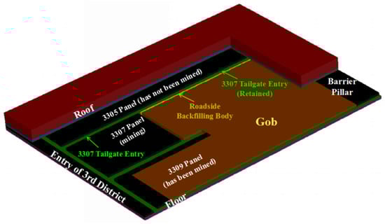
Figure 1.
3307 panel layout.
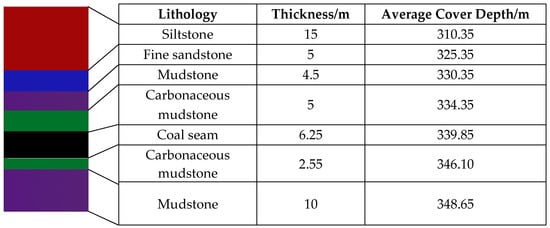
Figure 2.
Generalized stratigraphy column.
The coal-cutting height of shearer was 3100 ± 200 mm, and coal caving height was 3000 ± 100 mm. The bulking-controlled caving method was used for roof control. Top coal above three end shields at the corner of 3307 working face was not recovered, in order to maintain the entry.
Tailgate entry of 3307 panel was the RGE. Tailgate entry 3307 was driven along the floor of NO.3 coal seam. Its height and width were 3200 mm and 5800 mm, respectively. The width of the entry retained was 4800 mm. It was supported by the system consisting of high strength rebars, resins, lengthened rock bolts and strengthened cable bolts. The diameter of the high strength rebar was φ = 20 mm and length is 2200 mm. The plate for the rebar was a dome plate with dimensions of length × width × height = 150 × 150 × 10 mm. The cable bolt was 22 mm in diameter and 8300 mm in length. The plate for the cable bolt was also a dome plate with dimensions of length × width × height = 300 × 300 × 16 mm. A wire of 8# was used to weave the mesh that is 50 × 50 mm diamond mesh.
2.2. Roof Pre-Split and Pressure Relief
Pre-split holes were along the rib of the face side at the tailgate T-junction 10 m ahead of the working face. The pre-split holes were paralleled, their inclination with respect to the bedding plane was 75°. The diameter and the length of the blasting hole were 75 mm and 13,000 mm, respectively, as shown in Figure 3. The explosive used was grade three coal mine permitted emulsion explosive, and detonation velocity was greater than 3200 m/s. The coal permitted detonator, 8# millisecond delay electric detonator was used. The detonating cord was also coal permitted whose external diameter was 6.5 mm and detonation velocity was greater than 6000 m/s. The pre-split holes employed non-coupling continuous charging, and charge length and seal length were 7500 mm and 5500 mm, respectively. Four pre-split holes were detonated at a time using positive blasting.
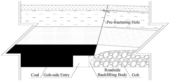
Figure 3.
Schematic of pre-split hole.
2.3. RBB and Concrete Wall
RBB was mainly composed of flexible formwork and concrete material. The flexible formwork was made up of external reinforced fiber cloth and internal bolt, which formed a closed three-dimensional space. It had characteristics of lightweight, high strength and convenient construction, as shown in Figure 4a. Inlet and fixing device were on its upper part. 500# high strength rebars were applied to the flexible formwork with a diameter of φ 22 × 1350 mm. The length of two threaded ends was more than 100 mm. The pattern of bolts was 700 × 750 mm. And both ends of a bolt had high strength plate, spherical and nylon washer. And the dimension of the high strength plate was 150 × 150 × 12 mm. The concrete material consisted of 425 ordinary Portland cement, sand, gravel and water. The ratio of cement to sand was 1:1.
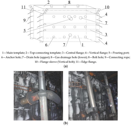
Figure 4.
Flexible formwork: (a) sketch diagram, and (b) physical diagram.
3. Strength Calculation of RBB
The mechanical model was established to calculate the strength of RBB. And the strength of RBB was calculated based on physical modeling of roof behavior and deformation of surrounding rock [28].
According to Figure 5, the deformation coordination of the mechanical model can be obtained:
where b is the height of RBB, m; h is the distance between the main roof and the immediate floor, m; m is the coal-cutting height of shearer, m.
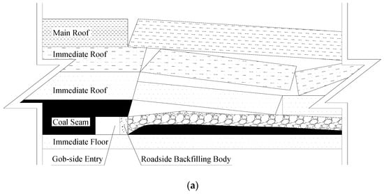
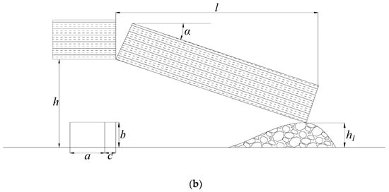
Figure 5.
Model for retained gob-side entry (RGE) in fully-mechanized top-coal caving panel: (a) diagram of gob-side entry and (b) mechanical model of gob-side entry.
and are:
where h1 is the distance between the floor to the point where the main roof block touches the gangue, m; a is the width of the RGE, m; c is the width of RBB, m; l1 is the pre-breaking position of the key block, m; l is the length of the broken block, m.
The distance between the floor to the point where the main roof block touches the gangue is:
where k is the bulking factor.
The vertical stress between the immediate roof and the RBB (e) is
where Eb is the elastic modulus of RBB; Ed is the elastic modulus of the immediate roof including the top coal.
According to the production conditions of 3307 FMLP, the following parameters were obtained: h = 15.75 m, m = 3.10 m, k = 1.05, a = 4.4 m, c = 1.4 m, b = 3.2 m, = 0.1 m, Ed = 25 GPa, Eb = 0.5 GPa. The length of fractured block (l) was 23 m, which was the periodic weighing of the basic roof. Because the roof pre-split was conducted on the side of RBB near the gob and the pre-split height had reached the main roof, the pre-split position of the key block (l1) was 0 m.
Substituting the above parameters, the vertical stress between the immediate roof and the RBB (e) was 35 MPa.
Therefore, the strength of the RBB was more than 35 MPa.
4. Numerical Simulation
The models were established and the parameters for the models were selected first. Then the roadway was excavated, pre-split, RBB establishment and coal seam extraction were executed. The reasonable pre-split angle was determined
4.1. Parameters for Rock Strata
The accuracy of the numerical simulation is generally related to the establishment of a model, including model size, mesh size, constitutive model, and rock mechanical parameters [29]. Hoek–Brown empirical strength criterion (H-B criterion) was put forward based on a large number of laboratory tests and on-site experiences. And it also had been modified and improved by many scholars, then widely used in rock mechanics engineering and other related disciplines [30,31]. Based on H-B criterion, parameters are determined in multiple coal seam mining in Renjiazhuang Coal Mine, the ground pressure behavior through numerical simulation was consistent with field measurement [32].
In order to obtain the H-B parameters mb, s and a, the parameters σci, GSI, mi and D of the intact rock of each stratum had to be obtained. σci values are obtained from the geological data provided by the coal mine. Also, some coal and rock mechanics experiments were carried out. GSI values were defined according to the rock cores from boreholes obtained from the entry as shown in Figure 6. And mi values were obtained from the software RocData (Roccience, Toronto, ON, Canada), which has a selection window to pick mi values according to the lithology. D values were set as 0 since the entry was driven using a header rather than blasting.
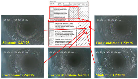
Figure 6.
Determination of GSI value.
The software of RocData estimates the parameter range of typical strata by its built-in program and obtains the parameters which generalized H-B criterion needs and M-C criterion corresponds with the background analysis, through collecting a large number of data of rock mechanics engineering around the world. The GHB parameters of each stratum that are obtained from RocData are shown in Table 1 [33]. Other parameters corresponding to the M-C criterion are shown in Table 2.

Table 1.
H-B parameters.
Table 2.
Equivalent M-C parameters for numerical simulation.
4.2. Model Development
Half of 3307 panel is taken to establish FLAC3D numerical model, whose dimensions are 160 m (length) × 10 m (width) × 48.3 m (height), and the height of the roof pre-split is 12.55 m. The angle of the pre-split hole is 0° (without pre-split), 45°, 60°, 75°, 90°. Besides, the number of meshes and nodes of each scheme is shown in Table 3. The model is shown in Figure 7 [34].
Table 3.
Details of the numerical models.
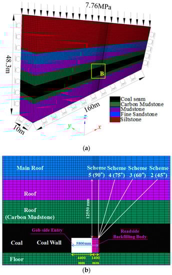
Figure 7.
Numerical model: (a) model schematic diagram and (b) enlarged view of area B.
According to the geological conditions, uniform stress of (340 − 29.5) m × 0.025 MN/m = 7.76 MPa was applied to the top of the model. The side boundaries were fixed transversely and the bottom boundary was fixed both horizontally and vertically. A significant distance (50 m) to the lateral boundaries and the bottom boundary was used to minimize the boundary effect. The layout of the RGE (3307 tailgate entry) was placed along the floor.
4.3. Simulation Steps
Before the extraction of the panel, the 3307 tailgate entry (3307 RGE) is first excavated along the floor, whose width is 5800 mm. And the width of the retained entry is 4800 mm. The width of the RBB is 1400 mm. Then the fully-mechanized panel is extracted. A very soft elastic material is used in the gob to approximately simulate the gangue [35,36]. At the same time, the RGE is retained.
5. Result Analysis and Discussion
5.1. Vertical Stress in RBB and Coal Wall
The vertical stress in RBB and coal wall of 3307 RGE has obvious differences when the roof pre-split angles are different, as shown in Figure 8. In RBB, the order of the peak load of vertical stress is 0° (without pre-split) >60° > 75° > 45° > 90°. However, the order of the coal wall is 0° (without pre-split) >45° > 60° > 75° > 90°. The order of stress concentration factor in the coal wall is 0° (without pre-split) >45° > 60° > 75° = 90°, as shown in Figure 9.
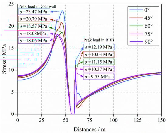
Figure 8.
Vertical stresses of model results with different angles.
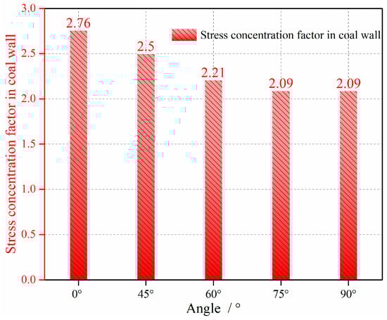
Figure 9.
Stress concentration factors in coal seam with different angles.
When the roof pre-split angle is 0° (without pre-split), the peak load in RBB is 12.19 MPa, while in the coal wall is 23.47 MPa and the stress concentration factor is 2.76. This indicates the maintenance of 3307 RGE is more difficult with the higher peak load and big RGE stress concentration factor.
When the pre-split angle increases from 0° to 45°, the peak load in RBB decreases dramatically from 12.19 MPa to 9.47 MPa and that in the coal wall decreases from 23.47 MPa to 21.25 MPa. Further, the stress concentration factor decreases from 2.76 to 2.5. Obviously, the peak loads in the RBB and coal wall both decrease. By using the roof pre-split, the vertical stress in the roof is intercepted, which is beneficial to reduce the stress of surrounding rock in the roof of RGE and reduce the stress concentration factor. Therefore, the deformation of RGE is distinctly reduced and the maintenance of RGE is much easier.
When the angles are 60°and 75°, respectively, the peak loads in RBB are 10.91 MPa and 10.81 MPa, with no obvious differences. And the peak loads in RBB are 18.81 MPa and 17.77 MPa, with a difference of 1.04 MPa. The stress concentration factors are 2.21 and 2.09, respectively. With the angles of 60° and 75°, there is no significant difference in the transfer of the vertical stress in the roof. The peak load in RBB is basically the same. And the difference between the peak load and the stress concentration factor in the coal wall is not obvious. However, the peak load is still reduced compared with the angle of 45°.
When the angle increases to 90°, the peak load in RBB is 8.71 MPa. Meanwhile, the peak load in the coal wall of 3307 RGE is 17.75 MPa, and the stress concentration factor is also 2.09. Compared with the other roof pre-split angles, the peak load both in RBB and coal wall is the minimum. When the angle is 90°, the surrounding rock of 3307 RGE is in the state of minimum stress, and the stress of RGE also decreases. And it is beneficial for the stability of the surrounding rock and maintenance of the RGE.
5.2. Position of Peak Load
When the roof pre-split angles are different, the positions of peak load have no difference in the middle of RBB of 3307 RGE, as shown in Figure 10. With different roof pre-split angles, the vertical stress increases gradually from 0 m (at the edge of RBB near 3307 RGE, the navy blue vertical dotted line showing in Figure 10) to 1.2 m (at the RBB near 3307 gob, the brown vertical dotted line showing in Figure 10), and decreases from 1.2 m to 1.4 m (at the edge of RBB near the 3307 gob, the orange vertical dotted line showing in Figure 10). And they are all in a state of asymmetric distribution. The peak load in RBB is at 1.2 m. That is, the position of peak load in RBB does not change with different angles, but the value decreases from 12.19 MPa to 8.71 MPa, as shown in Figure 11a. That shows the bearing capacity of RBB increases significantly with the increase of the roof pre-split angles.
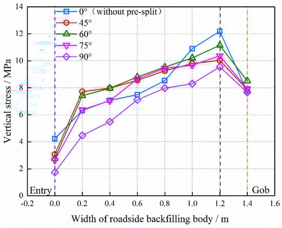
Figure 10.
Vertical stresses in the roadside backfilling body (RBB) with different angles.
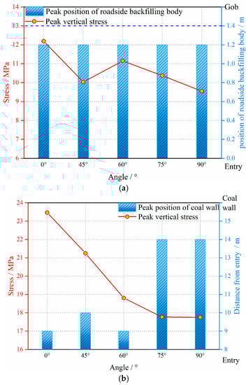
Figure 11.
Values and positions of peak load in RBB and coal wall: (a) values and positions of peak load in RBB and (b) values and positions of peak load in coal wall.
When the roof pre-split angles are different, the position of peak load has a slight difference in the coal wall of 3307 RGE, as shown in Figure 11b. The position of peak load in coal wall is about 9.5 m away from 3307 RGE when the angles are 0°, 45°, and 60°. However, when the angles are 75° and 90°, the position of the peak load in coal wall is about 14 m away from the entry. And the peak load in the coal wall decreases from 23.47 MPa to 17.75 MPa with the increase of roof pre-split angles from 0° to 90°. That suggests the position of peak load in the coal wall is located far away from 3307 RGE. It is more conducive to reduce the deformation of 3307 RGE and the maintenance requirements are lower.
5.3. Vertical Deformation of RBB
The vertical deformation of RBB is shown in Figure 12a. The vertical deformation of RBB gradually decreases and eventually becomes stable with the increase of the roof pre-split angles. The maximum vertical deformation, the minimum vertical deformation and the average vertical deformation with different angles are shown in Figure 12b. When the angle is 0°, the value of the vertical deformation (including the maximum vertical deformation, the minimum vertical deformation, and the average vertical deformation) of RBB is maximum. The average vertical deformation is up to 110.51 mm, but the value of the difference between the maximum and the minimum vertical deformation is not significant. When the angle is 45°, the average vertical deformation of RBB is 34.39 mm, which clearly decreases compared with that with the angle of 0°. That indicates the effect is more obvious to reduce the vertical deformation of RBB. The difference in the value between the maximum and the minimum vertical deformation is 38.38 mm. When the angles are 60° and 75°, respectively, the average vertical deformation is 9.86 mm and 7.52 mm. The differences between the maximum and the minimum vertical deformation are 37.47 mm and 22.43 mm, respectively. The vertical deformation is still reduced compared with the angle of 45°, including the maximum vertical deformation, the minimum vertical deformation and the average vertical deformation. When the angle is 90°, however, the average vertical deformation is 6.1 mm, which is minimal compared with other roof pre-split angles. The difference between the maximum and the minimum vertical deformation is 6.95 mm, which means the vertical deformation of RBB tends to be leveled off.
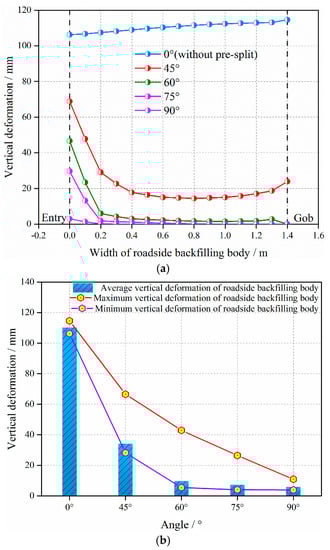
Figure 12.
Vertical deformation of RBB with different roof pre-split angles: (a) vertical deformation of the RBB with different angles and (b) average, maximum and minimum vertical deformation of the RBB with different angles.
The positions of the maximum and the minimum vertical deformation of RBB also have obvious differences with different roof pre-split angles, as shown in Figure 13. When the angle is 0°, the position of the maximum vertical deformation is at the edge of RBB near the 3307 gob with a value is 114.61 mm, and the one of minimum vertical deformation is at the edge of RBB near the 3307 RGE with a value of 106.24 mm. However, when the angle is 45°, the positions of the maximum and the minimum vertical deformation are at the edge of RBB near the 3307 RGE and middle of the RBB (at the RBB near the 3307 gob), respectively. In addition, the values of maximum and minimum vertical deformation are 66.56 mm and 28.18 mm, respectively, which indicates that the value of vertical deformation obviously decreases with the roof pre-split angle. Therefore, the roof pre-split is useful to reduce the vertical deformation of RBB and keep the RBB integrity compared with the angle of 0°. When the angles are 60° and 75°, there is no difference in position with the angle of 45° except the value. The values of the maximum vertical deformation are 42.9 mm and 45.43 mm, and the values of the minimum vertical deformation are 5.43 mm and 4.03 mm. When the angle is 90°, the position of the maximum and the minimum vertical deformation have no difference with the angles of 45°, 60°, and 75°. The maximum and the minimum vertical deformation are 10.87 mm and 3.92 mm, respectively. Compared with the values of the average, maximum and minimum vertical deformation under different roof pre-split angles, they all have an obvious difference that they are all the minimum when the angle is 90°. That also indicates that vertical deformation of the RBB is the smallest when the angle is 90°, which means the vertical deformation of the RBB is small and the RBB can keep better integrity to maintain the stability of 3307 RGE.
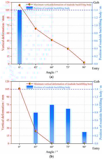
Figure 13.
Values and positions of maximum and minimum vertical deformation of RBB with different angles: (a) values and positions of the maximum vertical deformation of RBB and (b) values and positions of the minimum vertical deformation of RBB.
According to practical application situation of roof pre-split in 3307 fully-mechanized longwall panel and the numerical modeling analysis of the overall environment of 3307 gob-side entry in the five numerical models, the optimum pre-split angle is 90°. The reasons are as follows: when the pre-split angle is 90°, the stress environment (the vertical stress in RBB and the coal wall) of the 3307 gob-side entry is minimum. The stress concentration factor in coal wall is smaller than other angles. And the vertical deformation of the RBB also is the smallest. The difference between the maximum and minimum vertical deformation is not significant which means the RBB tends to present a uniform vertical deformation. That demonstrates that the stability of the 3307 gob-side entry is much easier to maintain. Considering economic factor and the labor intensity factor, the time of drilling a hole is shortened, the intensity of labor of miners decreases and the cost of pre-split also reduces, because the length of the pre-split hole is the smallest when the pre-split height is the same.
6. Conclusion Remarks
Based on geological conditions and field practice, numerical modeling was performed to study the stress of surrounding rock and the vertical stress and deformation of RBB of the RGE with different roof pre-split angles. The following conclusions can be drawn.
By establishing the mechanical model of support strength of RBB, it is finally determined that the support strength of the RBB cannot be less than 35 MPa, according to the coordinate relation of deformation and the geological conditions of the 3307 panel.
The stress of the surrounding rock of RGE is affected by the roof pre-split angle. The order of the vertical peak load is 0° (without pre-split) >60° > 75° > 45° > 90° in RBB, and the order of it in coal wall is 0° (without pre-split) >45° > 60° > 75° > 90°. Meanwhile, with the increase of the roof pre-split angles, the vertical stress and deformation of RBB gradually decrease, which means that the RBB is more helpful to maintain the stability of the RGE.
The positions of peak load in coal wall have an obvious difference with different roof pre-split angles, but the positions in the RBB are the same. With the increase of roof pre-split angle, the position in the RBB is at the 1.2 m (at the RBB near the gob), but the position of peak load in the coal wall is far away from the RGE, which is more conducive to reduce the vertical deformation and is more convenient for the maintenance of 3307 RGE.
The vertical stress of the surrounding rock of RBB and the characteristics of the vertical stress and deformation of the RBB under the different roof pre-split angles are analyzed synthetically. When the angle is 90°, the stress of the surrounding rock of the RGE is the minimum and the vertical stress and deformation of the RBB are also the minimum. Therefore, the roof pre-split angle can be determined to be 90°, which is more favorable for the operation of RGE in fully mechanized longwall top coal caving panels.
Author Contributions
All authors contributed equally.
Funding
This study was funded by the Joint Research Fund under cooperative agreement between the National Natural Science Foundation of China (NSFC) and Funds for Coal-Based Low-Carbon Technology of Shanxi (No. U1710258), the National Natural Science Foundation of China (No. 51574172), Program for Key Research Project of Shanxi Province in the Field of Social Development, (No. 201803D31044), Program for“1331” Key Team of Scientific and Technology Innovation in Shanxi Province, Program for the Excellent Innovation Team of Higher Learning Institutions of Shanxi Province, Program for the Leading Talents of Emerging Industry of Shanxi Province, Shanxi Province Technology Innovation Program for the Key Team, the National Natural Science Foundation of China, Young Scientists Fund (No. 51804209), and Shanxi Applied Basic Research Programs, Science and Technology Foundation for Youths (No. 201801D221363).
Conflicts of Interest
The authors declare no conflict of interest.
References
- Yin, Y.C.; Zhao, T.B.; Zhang, Y.B.; Tan, Y.L.; Qiu, Y.; Taheri, A.; Jing, Y. An innovative method for placement of gangue backfilling material in steep underground coal mines. Minerals 2019, 9, 107. [Google Scholar] [CrossRef]
- Zhang, J.; Taheri, A.; Deng, J.R.; Ke, B. Effects of superplasticizer on the hydration, consistency, and strength development of cemented paste backfill. Minerals 2018, 8, 381. [Google Scholar] [CrossRef]
- Zhao, Y.; Soltani, A.; Taheri, A.; Karakus, M.; Deng, A. Application of slag-cement and fly ash for strength development of cemented paste backfills. Minerals 2019, 9, 22. [Google Scholar] [CrossRef]
- Zhang, J.X.; Li, M.; Taheri, A.; Zhang, W.Q.; Wu, Z.Y.; Song, W.J. Properties and application of backfill materials in coal mines in China. Minerals 2019, 9, 53. [Google Scholar] [CrossRef]
- Yuan, L. Theory and Practice of Integrated Pillarless Coal Production and Methane Extraction in Multiseams of Low Permeability; China Coal Industry Publishing House: Beijing, China, 2010. [Google Scholar]
- Miao, X.X. Review of research on mechanical behaviors of mining rock mass and its related engineering technological innovation progress. Chin. J. Rock Mech. Eng. 2010, 2929, 1988–1998. [Google Scholar]
- Zhang, P.S.; Lin, D.C. Technology of the Retaining Gob-Side Entry; China University of Mining and Technology Press: Xuzhou, China, 2014. [Google Scholar]
- Gong, P.; Ma, Z.G.; Zhang, R.R.C.; Ni, X.Y.; Liu, F.; Huang, Z.M. Surrounding rock deformation mechanism and control technology for gob-side entry retaining with fully mechanized gangue backfilling mining: a case study. Shock Vib. 2017, 2017. [Google Scholar] [CrossRef]
- Li, X.H.; Ju, M.H.; Yao, Q.L.; Zhou, J.; Chong, Z.H. Numerical investigation of the effect of the location of critical rock block fracture on crack evolution in a gob-side filling wall. Rock Mech. Rock Eng. 2016, 49, 1041–1058. [Google Scholar] [CrossRef]
- Chen, Y. Study on Stability Mechanism of Rockmass Structure Movement and its Control in Gob-Side Entry Retaining; China University of Mining and Technology: Xuzhou, China, 2012. [Google Scholar]
- Feng, G.R.; Wang, P.F.; Chugh, Y.P. Stability of gate roads next to an irregular yield pillar: A case study. Rock Mech. Rock Eng. 2018, 1–20. [Google Scholar] [CrossRef]
- Feng, G.R.; Wang, P.F.; Chugh, Y.P. A new gob-side entry layout for longwall top coal caving. Energies 2018, 11, 1292. [Google Scholar] [CrossRef]
- Wang, P.F.; Zhao, J.L.; Feng, G.R.; Wang, Z.Q. Improving stress environment in development entries through an alternate longwall mining layout. Arab. J. Geosci. 2018, 11, 44. [Google Scholar] [CrossRef]
- Zhao, J.L.; Wang, P.F.; Su, Y. An innovative longwall mining technology in Tangshan coal mine, China. Minerals 2017, 7, 14. [Google Scholar] [CrossRef]
- Yang, H.Y.; Cao, S.G.; Wang, S.Q.; Fan, Y.C.; Wang, S.; Chen, X.Z. Adaptation assessment of gob-side entry retaining based on geological factors. Eng. Geol. 2016, 209, 143–151. [Google Scholar] [CrossRef]
- Yan, S.; Bai, J.B.; Wang, X.Y.; Huo, L.J. An innovative approach for gateroad layout in highly gassy longwall top coal caving. Int. J. Rock Mech. Min. Sci. 2013, 59, 33–41. [Google Scholar] [CrossRef]
- Ma, L.Q.; Zhang, D.S.; Chen, T.; Fang, G.W. Study on packing body supporting resistance of enter-in packing for in-situ gob-side entry retaining in fully-mechanized top-coal caving mining face. Chin. J. Rock Mech. Eng. 2007, 3, 544–550. [Google Scholar]
- Zhang, D.S.; Miao, X.X.; Mao, X.B. Simulation on roof activities of gob-side entry retaining in fully-mechanized top-coal caving faces. J. Chin. Univ. Mining Technol. 2001, 3, 47–50. [Google Scholar]
- Zhang, D.S.; Mao, X.B.; Ma, W.D. Testing study on deformation features of surrounding rocks of gob-side entry retaining in fully-mechanized coal face with top-coal caving. Chin. J. Rock Mech. Eng. 2002, 3, 331–334. [Google Scholar]
- Tan, Y.L.; Yu, F.H.; Ning, J.G.; Zhao, T.B. Design and construction of entry retaining wall along a gob side under hard roof stratum. Int. J. Rock Mech. Mining Sci. 2015, 77, 115–121. [Google Scholar] [CrossRef]
- Zhang, Z.Z.; Bai, J.B.; Chen, Y.; Yan, S. An innovative approach for gob-side entry retaining in highly gassy fully-mechanized longwall top-coal caving. Int. J. Rock Mech. Mining Sci. 2015, 80, 1–11. [Google Scholar] [CrossRef]
- Guo, P.F.; Zhang, G.F.; Tao, Z.G. Blasting technology of gateway retaining along goaf pressure release by roof cutting in hard and weak complex roof. Coal Sci. Technol. 2016, 44, 120–124. [Google Scholar]
- Wang, X.H. Study on the Mechanism of the Pressure Relief by Roof Cutting in Gob-Side Entry Retaining. Master’s Thesis, Anhui University of Science and Technology, Huainan, China, 2017. [Google Scholar]
- Hao, F.K.; Zhou, T.X.; Jiang, Y.C. Forced roof caving technology and application to goaf-side entry retaining. Coal Sci. Technol. 2006, 2, 16–24. [Google Scholar]
- Gao, K.; Liu, Z.G.; Liu, J.; Deng, D.S.; Gao, X.Y.; Kang, Y.; Huang, K.F. Application of deep borehole blasting to gob-side entry retaining forced roof caving in hard and compound roof deep well. Chin. J. Rock Mech. Eng. 2013, 32, 1588–1594. [Google Scholar]
- Zhao, Y.M.; Zhang, N.; Zheng, X.G.; Li, B.Y. Structural optimization of overlying strata for gob-side entry retaining in 1000 m deep mine with direct thick and hard roof. J. Mining Safety Eng. 2015, 32, 714–720. [Google Scholar]
- Sun, X.M.; Liu, X.; Liang, G.F.; Wang, D.; Jiang, Y.L. Key parameters of gob-side entry retaining formed by roof cut and pressure releasing in thin coal seams. Chin. J. Rock Mech. Eng. 2014, 33, 1449–1456. [Google Scholar]
- Zhang, D.S.; Miao, X.X.; Feng, G.M.; Song, Z.Q. Stability control of packing body for gob-side entry retaining in fully-mechanized coalfaces with top-coal caving. J. Chin. Univ. Mining Technol. 2003, 32, 232–235. [Google Scholar]
- Wang, P.F.; Zhao, J.L.; Wang, Z.Q.; Sun, Z.W.; Xu, C.H.; Song, Z.Y.; Su, Y. Mechanism of gob-pillar interaction for subcritical panels and its application. Chin. J. Rock Mech. Eng. 2017, 36, 1185–1200. [Google Scholar]
- Hoek, E.; Carranza, T.; Corkum, B. Hoek-Brown Criterion. In Proceedings of the NARMS-TAC Conference, Toronto, ON, Canada, 7–12 July 2002; pp. 267–273. [Google Scholar]
- Hoek, E.; Diederichs, M.S. Empirical estimation of rock mass modulus. Int. J. Rock Mech. Mining Sci. 2006, 43, 203–215. [Google Scholar] [CrossRef]
- Zhao, Y.X.; Wang, T.; Jiang, Y.D.; Pan, L.; Zhang, K.X. Application of Hoek-Brown criterion in numerical simulation of ground pressure features in multi-seam longwall mining. J. Chin. Coal Soc. 2013, 38, 970–976. [Google Scholar]
- Roc Data. Available online: https://www.rocscience.com/rocscience/products/rocdata (accessed on 10 October 2016).
- Itasca. Fast Lagrangian Analysis of Continua in 3 Dimension. User’s Guide; Itasca: Minneapolis, MN, USA, 2007; Version 3.1. [Google Scholar]
- Wang, H.W.; Jiang, Y.D.; Zhao, Y.X.; Zhu, J.; Liu, S. Numerical investigation of the dynamic mechanical state of a coal pillar during longwall mining panel extraction. Rock Mech. Rock Eng. 2013, 46, 1211–1221. [Google Scholar] [CrossRef]
- Jiang, Y.D.; Wang, H.W.; XUE, S.; Zhao, Y.X.; Zhu, J.; Pang, X.F. Assessment and mitigation of coal bump risk during extraction of an island longwall panel. Int. J. Coal Geol. 2012, 95, 20–33. [Google Scholar] [CrossRef]
© 2019 by the authors. Licensee MDPI, Basel, Switzerland. This article is an open access article distributed under the terms and conditions of the Creative Commons Attribution (CC BY) license (http://creativecommons.org/licenses/by/4.0/).