Article

Continuously Variable-Frequency Energy-Encrypted Wireless Power Transfer

1
Department of Electrical and Electronic Engineering, The University of Hong Kong, Hong Kong, China
2
School of Electrical and Information Engineering, Tianjin University, Tianjin 300072, China
*
Author to whom correspondence should be addressed.
Energies 2019, 12(7), 1286; https://doi.org/10.3390/en12071286
Submission received: 3 March 2019 / Revised: 21 March 2019 / Accepted: 1 April 2019 / Published: 3 April 2019
(This article belongs to the Section F: Electrical Engineering)

Abstract

:
This paper proposes and implements a novel continuously variable-frequency energy-encrypted wireless power transfer (WPT) system for wireless energy security in multi-receiver applications. To prevent wireless energy from being illegally stolen, the proposed chaotic 2-D frequency-and-duration encryption (FDE) technology directly generates well-defended security keys to guarantee energy security. An LCC-compensated transmitter without using a switched-capacitor array is proposed to competently encrypt the wireless energy into burglarproof energy packages, which are decrypted only by authorized receivers. Then, the concept of the static variable capacitor (SVC) is presented to achieve dynamical impedance compensation for wireless energy decryption in authorized receivers with knowledge of security keys. Consequently, the proposed energy-encrypted SVC-based WPT system can flexibly encrypt and decrypt wireless energy packages in a continuous frequency-and-duration adjustment rather than in a discrete way, thus greatly improving energy security performance. Theoretical analysis, computer simulation and experimental results are provided to verify the feasibility of the proposed continuously energy-encrypted SVC-based WPT system.

1. Introduction

Wireless power transfer (WPT), first proposed by Nikola Tesla, can be traced back to more than one hundred years ago [1]. Recently, the WPT possesses the key advantages of cordless, spark-proof, better convenience and higher flexibility, and thus has re-attracted unpreceded attention of consumers, manufacturers and academic researchers [2,3,4]. This wireless energy-accessing pattern is gradually improving our conventional plug-in charging pattern and meanwhile alleviating the limitations of current battery techniques. As one of most epoch-making technologies, the WPT shows great talents and potentials in various industrial applications and interdisciplinary areas, such as domestic appliances or medical electronics [5,6,7], electric vehicle (EV) wireless charging [8,9,10], wireless motor drive [11,12] and emerging wireless energy security [13,14].
The working principle of magnetic resonant coupling (MRC) was first proposed and experimentally demonstrated as a significant promotion on WPT techniques in 2007 [15]. Due to its high efficiency and high-power capability, the MRC-based WPT has been rapidly identified as one of the most promising implementation ways for near-field power transmission. Although the WPT successfully removes the messy charging wires, it inevitably takes the risks of energy stealing or leakage because of such convenient wireless energy-accessing pattern. Although a selective WPT technology can achieve oriented power transmission to specified receivers among multi-receivers [11,16], the illegal receivers may track and lock the fixed operating frequency to steal the wireless power. Accordingly, to guarantee wireless energy security, the concept of energy encryption was proposed to encrypt the wireless energy as the information encryption does, which ensures that only authorized receivers can successfully decrypt and harvest the encrypted wireless energy [9,13]. However, these encryption schemes desire switched-capacitor arrays to discretely adjust the operating frequency and matched capacitance, thus suffering from discrete adjustment, finite selections and low flexibility.
Therefore, a practical variable capacitor awaits to be developed for continuously variable-frequency energy-encrypted WPT systems. A transistor-controlled variable capacitor was proposed for stabilizing soft-switching operation [17,18], but its tested power level is relatively low. The mechanisms of virtual capacitors [19], electric springs [20] and single-phase var generators [21] can be used to develop a static variable capacitor (SVC) for continuous impedance compensation, and thus wireless energy encryption and decryption. Incorporated with the merits of LCC-compensated transmitter [22,23,24] and the variable-frequency characteristics of a series-to-series (SS) WPT system using fixed compensation [9,16], a novel LCC-compensated switched-capacitorless energy-encrypted transmitter is proposed, which tactfully avoids the usage of an extra SVC in the transmitter.
The rest of this paper is organized as follows. Section 2 will discuss the topology and operation principle of the proposed continuously variable-frequency energy-encrypted WPT system. Section 3 will present the directly 2-D frequency-and-duration encryption (FDE) and the SVC decryption. Section 4 will be devoted to the computational simulation of electromagnetic fields and system circuit. In Section 5, an experimental prototype will be constructed and tested to verify the proposed continuously energy-encrypted SVC-based WPT system. A conclusion will be drawn in Section 6.

2. Topology and Operating Principle

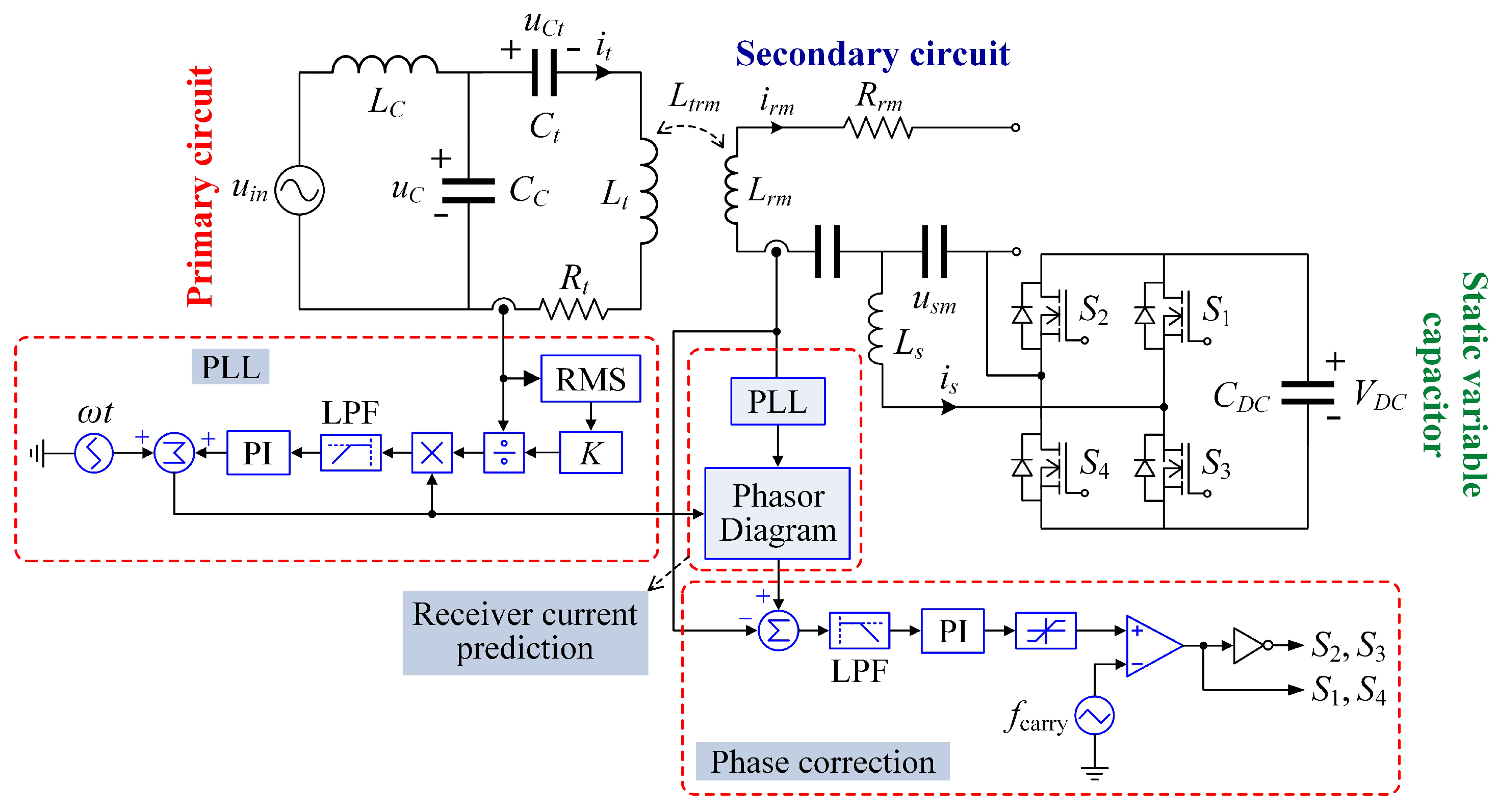
2.1. System Topology

By eliminating the messy charging wires, WPT can possess various merits of cleanness, convenience and flexible mobility over conventional plug-in charging pattern, but wireless energy security is gradually recognized as a key concern by consumers and manufacturers. Energy-encrypted WPT systems can prevent transgressors from illegally stealing wireless energy and thus improve energy security performance in the multiple-objective WPT-based applications, such as static park-charging EVs, dynamic roadway-charging EVs and wireless charging consumer or medical electronics.
Figure 1 depicts the proposed continuously variable-frequency energy-encrypted WPT system using the SVC in receivers. The whole system mainly comprises of one LCC-compensated switched-capacitorless transmitter and multiple receivers, including the authorized and unauthorized ones. It is worth noting that the LCC-compensated transmitter without using a switched-capacitor array can offer a definite merit of flexibly encrypting the wireless energy by continuously adjusting the operating frequency and its active duration. The concept of the SVC is newly introduced to achieve dynamic impedance compensation in the authorized receiver circuits. With knowledge of security keys, only the authorized receivers can accordingly decrypt the wireless energy packages encrypted by the LCC-compensated switched-capacitorless transmitter. Moreover, a chaotic 2-D FDE technology is directly used to generate a sequence of more defensive security keys for the superior wireless energy encryption.

2.2. Operating Principle

As depicted in Figure 1, Rt, Lt, Ct, it, Rrk, Lrk, Crk and irk (k Z+, and k = 1,…, m, …, n) with subscripts t and r denote the coil internal resistances, resonant coil inductances, matched capacitances and currents in the transmitter and receiver circuits in the kth energy-encrypted WPT channel, respectively. For example, if k = m, Rrm and irm are the coil internal resistances and resonant currents in the receiver circuits in the mth energy-encrypted WPT channel as shown in Figure 1. Besides, Ltrk and L r k 1 k 2 (k1, k2 [1, n]) denote the mutual inductance between the transmitter coil and the kth receiver coil and that between the k1th and k2th receiver coils, respectively. The inductor LC, capacitor CC and capacitor Ct form the LCC-compensated network in the transmitter side. In the circuit of the proposed SVC, Lsk is the smoothing inductor, and CDCk and Csk represent the capacitors in the DC and AC sides, respectively. Similarly, if k = m, Csm is the AC-side capacitor in the mth receiver circuits in Figure 1.
To commence with theoretical analysis, some assumptions are made: (i) Lrk = Lr, Ltrk = Ltr, Rrk =Rr, and RLk = RL. (ii) RLk_eq is the equivalent resistance of load resistance RLk, and RLk_eq = 8RLk2. (iii) Ltrk >> L r k 1 k 2 , and L r k 1 k 2 can be regarded as zero. In each energy-encrypted WPT channel, the initial operating frequency fk is given by
f k = 1 2 π L r k C r k , k = 1 , 2 , 3 n , n Z +
where n is the total number of energy-encrypted channels. When the mth group of receivers is authorized to decrypt and harvest the wireless energy-encrypted packages, the authorized mth receivers will operate at the mth operating frequency fm. According to the security keys of the FDE sequences, delivered from the energy-encrypted transmitter, both operating frequency fm and its duration may chaotically change, and the SVC in the authorized receivers will be rapidly activated for impedance compensation. Meanwhile, the switched-capacitorless energy-encrypted transmitter will operate at the same chaotic FDE sequences to dynamically encrypt the wireless energy. Consequently, both the transmitter and the mth group of authorized receivers operates at the chaotic operating frequency fm. In such a way, the general equation can be derived as:
Z L C Z C 0 0 0 0 Z C Z t Z t r 1 λ 1 Z t r 2 λ 2 Z t r m λ m Z t r n λ n 0 Z t r 1 Z r 1 Z r 12 λ 2 Z r 1 m λ m Z r 1 n λ n 0 Z t r 2 Z r 12 λ 1 Z r 2 Z r 2 m λ m Z r 2 n λ n 0 Z t r m Z r 1 m λ 1 Z r 2 m λ 2 Z r m Z r m n λ n 0 Z t r n Z r 1 n λ 1 Z r 2 n λ 2 Z r m n λ m Z r n i L C i t i r 1 i r 2 i r m i r n = U in 0 0 0 0 0
where Z L C = j ω L C + 1 j ω C C , Z C = 1 j ω C C , Z t r k = j ω m L t r k and Z r k 1 k 2 = j ω m L r k 1 k 2 . Denotation Uin is the root-mean-square (RMS) value of the input voltage uin, and ωm is the angular frequency corresponding to fm. In Equation (2), Zt, Zrk and Zrm represent the impedances in the transmitter circuit, the kth and authorized mth receiver circuits operating at fm, respectively. They can be calculated as:
{ Z t = R t + j ω m L t + 1 j ω m C t Z r k = R L k + R r k + j ω m L r k + 1 j ω m C r k Z r m = R L m _ eq + R r m
The total impedance Zref reflected from all receiver circuits to the transmitter circuit can be derived as:
Z ref = k = 1 n λ k Z ref k = k = 1 , k m n λ k Z ref k + λ m ( ω m L t r m ) 2 R r m + R L m _ eq λ m ( ω m L t r m ) 2 R r m + R L m _ eq + j Im ( k = 1 , k m n λ k Z ref k )
where Z ref k = ( ω m L t r k ) 2 Z r k , which is the kth impedance Zrefk reflected from the kth receiver circuits. Besides, λk obeys a random distribution, which represents the number of receivers in the kth energy-encrypted WPT channel. Accordingly, in order to guarantee superior energy security performance, the reflected impedances from the authorized and unauthorized receivers, respectively, should satisfy the following inequality:
λ m ( ω m L t r m ) 2 R r m + R L m _ eq > > Im ( k = 1 , k m n λ k Z ref k ) > > Re ( k = 1 , k m n λ k Z ref k )
where Re() and Im() are the real and imaginary parts of complex impedance, respectively.
In the transmitter circuit, the total impedance Zt_total and the input impedance Zin in the inverter output side can be respectively calculated as:
Z t _ total = Z ref + Z t ,   Z in = R C + j ω m L C + Z t _ total Z C Z t _ total + Z C
where RC is the internal resistance of LC.
Accordingly, the input current iin and the transmitter current it can be respectively expressed as:
i in = U in Z in ,   i t = Z C Z C + Z t _ total i in
Also, the input impedance angle φ and the input power Pin can be respectively written as:
φ = arctan ( Im ( Z in ) Re ( Z in ) ) ,   P in = U in | i in | cos φ
The current irk through the kth receiver circuit, the total output power Poutk and its corresponding transmission efficiency ηk in the kth energy-encrypted WPT channel can be respectively expressed as:
i r k = j ω m L t r k i t Z r k ,   P out k = λ k | i r k | 2 R L k _ eq ,   η k = P out k P in
Thus, the kth transmission efficiency ηk can be derived as:
η k = λ k R L k ( ω m L t r k ) 2 | Z r k | 2 ( ω m C C ) 2 R C ( R t r 2 + ( ω m L t 1 ω m C C 1 ω m C t + Im ( k = 1 , k m n λ k Z ref k ) ) 2 ) + R t r
where R t r = Re ( k = 1 n λ k Z ref k ) + R t , and the key derivation is listed as (A1) in the Appendix.
According to Equation (10), ηk is impervious of LC. Particularly, when the mth receivers are authorized, the corresponding transmission efficiency ηm of the authorized mth receivers can be rewritten as:
η m = λ m R L m ( ω m L t r m ) 2 R L m _ eq + R r m 2 ( ω m C C ) 2 R C Re k = 1 n λ k ( ω m L t r k ) 2 Z r k + R t 2 + ω m L t 1 ω m C C 1 ω m C t + Im k = 1 , k m n λ k ( ω m L t r k ) 2 Z r k 2 + R t r = λ m R L m ( ω m L t r m ) 2 R L m _ eq + R r m 2 1 ( ω m C C ) 2 R 1 T r 2 + T c 2 + T r
where resistance coefficients (Tr and Trrk) and conductance coefficients (Tc, Ttc, Trc and Trck) in the transmitter and receiver circuits can be respectively defined as:
T r = Re k = 1 n λ k ( ω m L t r k ) 2 Z r k + R p Re k = 1 n λ k ( ω m L t r k ) 2 Z r k λ m ( ω m L t r m ) 2 R r m + R L m _ eq T c = ω m L t 1 ω m C t 1 ω m C C + k = 1 , k m n λ k ( ω m L t r k ) 2 T r c k ( T r r k 2 + T r c k 2 ) T t c = ω m L t 1 ω m C t 1 ω m C C < 0 T r c = k = 1 , k m n λ k ( ω m L t r k ) 2 T r c k ( T r r k 2 + T r c k 2 ) T r r k = R r k + R L k _ eq T r c k = 1 ω m C r k ω m L r k
Also, its key derivation is listed as (A2) in the Appendix.
To prevent the unauthorized receivers from stealing wireless energy, the unauthorized receiver currents should be far less than the authorized ones, and it can even be neglected. Thus, the energy-encrypted WPT system should always keep satisfying the following inequality:
j ω m L t r m | i t | ( R r m + R L m ) / λ m > > max ( j ω m L t r k | i t | | Z r k | / λ k ) ,   k m
which also indicates that irm through the mth authorized receiver circuit is not less than ε times of the maximum value of irk (km) through all the unauthorized ones, and thus there is:
{ P out m ε 2 P out k η m ε 2 η k ,   i r m ε i r k ,   k m ,   ε R +
Assuming L t r m = L t r k = L t r , in order to guarantee relatively high transmission efficiency, the impedance in the authorized receiver circuits should be much less than the minimum one in all the unauthorized receiver circuits. Hence, there is a constraint condition:
R r m + R L m λ m < < min ( | Z r k | λ k ) R r m + R L m λ m < < min ( Im ( Z r k ) λ k ) ,   k m
Accordingly, the transmission efficiencies ηk and ηm are impervious to the parameter LC of the LCC compensation network in the transmitter circuit. Although the internal resistance of LC will lead to extra power loss, the proposed energy encryption scheme takes the advantage of continuous frequency adjustment without using bulky switched-capacitor arrays [13]. Inevitably, the proposed continuously energy-encrypted SVC-based WPT system may suffer from a disadvantage in terms of additional complexity and slightly deteriorated efficiency of the security-enhanced WPT system.

3. Frequency-and-Duration Encryption and Static Variable Capacitor Decryption

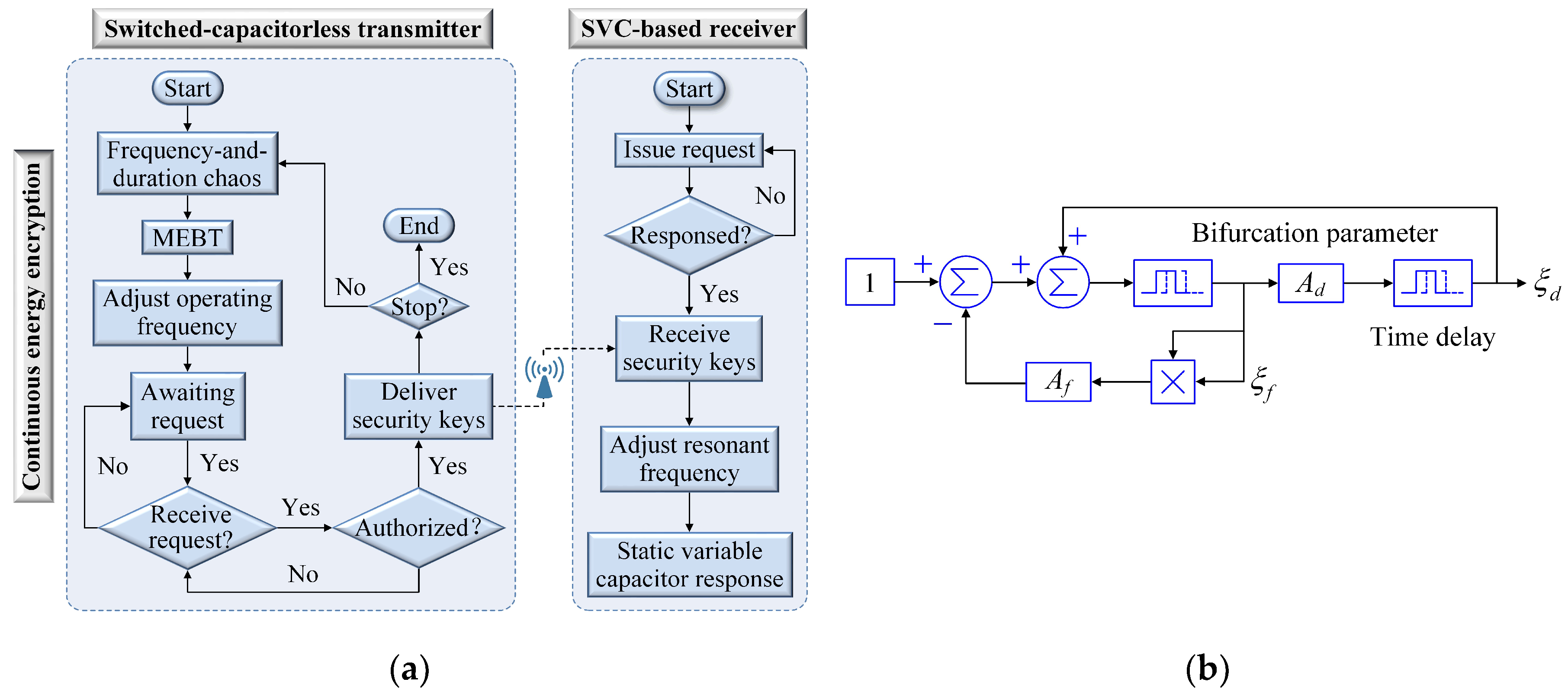
3.1. Chaotic 2-D Frequency-and-Duration Encryption

The key of energy encryption mainly relies on the frequency sensitivity in the conventional MRC-based WPT systems. The proposed continuously variable-frequency energy encryption scheme is detailed depicted in Figure 2, where the encryption and decision-making unit generates the defensive chaotic 2-D FDE sequences, namely the security keys. Based on the wireless data interaction between the energy-encrypted transmitter and energy-decrypted receivers, the encryption and decision-making unit will conduct the maximum efficiency band tracking (MEBT) to suppress the wireless energy leakage. Practically, the operating frequencies of the unauthorized receivers always dynamically and randomly change, which will unexpectedly result in an increasing probability of energy stealing or leakage. Thus, the MEBT will dynamically optimize the frequency band of energy encryption for maximizing transmission efficiency. According to the optimized security keys, the LCC-compensated switched-capacitorless transmitter will encrypt the wireless energy into encoded energy packages. This energy encryption is realized by proactively attuning both the switching frequency and its duration to the FDE security keys in a continuous way. After certificating the authorization of specific receivers, the FDE security keys will be secretly delivered to the authorized receivers. With knowledge of the FDE security keys, the authorized receivers will decrypt the encoded energy packages by conducting the proposed SVC-based impedance compaction. Thus, they can effectively harvest wireless energy from the proposed continuously variable-frequency energy-encrypted WPT system. Due to the lack of security keys, the unauthorized receivers can pick up only an insignificant level of encrypted wireless energy.
In Figure 2b, a chaotic 2-D FDE algorithm is directly adopted to dynamically generate the encrypted frequency and its active duration sequences – the security keys. It plays an important role in ensuring wireless energy security. The Hénon map is used to generate a 2-D discrete-time chaotic series [25,26] as given by:
{ ξ f _ i + 1 = ξ d _ i + 1 A f ξ f _ i 2 ξ d _ i + 1 = A d ξ f _ i , A f [ 1.0 , 1.5 ] , A d = 0.3
where ξf_i and ξd_i are the chaotic sequences of the energy-encrypted frequency and its duration, respectively, and Af and Ad are the corresponding bifurcation parameters. To produce the desired random-like but bounded security keys (ξf, ξd) for the proposed continuously energy encryption scheme, Af = 1.4 is selected [26]. Hence, the chaotic security keys γi and βi can be expressed as:
{ γ i = a γ + b γ ξ f _ i , 0 < 1 . 5 b γ < a γ β i = a β + b β ξ d _ i ,   0 < 0 . 4 b β < a β
Both the encrypted angular frequency ωm and its duration Dm can be respectively expressed as:
{ ω m = γ i ω 0 D m _ q = β i D 0 , q Z +
Thus, the encrypted operating angular frequency and its duration can be chaotically varied in the proposed continuously energy-encrypted WPT system. Generally, ω0 and D0 can be arbitrarily designed based on the power level and transmission distance. Instead of simultaneously regulating switched-capacitor arrays in both the transmitter and the authorized receivers [13], the LCC-compensated switched-capacitorless transmitter can self-adaptively attune the switching frequency to synchronize the FDE security keys. Meanwhile, the authorized receivers just need to activate the SVC for dynamic impedance compensation and energy decryption. Accordingly, the equivalent matched capacitor will be adjusted as:
C r b ( q = 1 q = i ( β i D 0 ) ) = 1 r i 2 1 ω 0 2 L r b
Consequently, the encoded energy package can only be decrypted by these authorized receivers with knowledge of security keys.

3.2. Static Variable Capacitor Decryption

The wireless energy decryption can be realized by adjusting the compensated impedance. Since the coupling characteristics are pre-determined by the transmitter and receiver coils, the capacitance is normally chosen as the control objective for the impedance compensation. The capacitor array [27] and the capacitor matrix [28] were reported, but identified as finite capacitance selections. This discrete energy encryption scheme [13] desires to simply increase the alternative capacitors, which will inevitably deteriorate the practicability and applicability of energy-encrypted WPT systems using bulky switched-capacitor arrays. Accordingly, this paper proposes and implements an SVC scheme for impedance compensation by controlling the output current to simulate the voltage-current characteristic of a real capacitor or inductor. Theoretically, the proposed SVC can offer infinite capacitance selections by adjusting the compensated impedance in a continuous way, thus significantly improving the energy security performance for multi-receiver WPT systems.
Generally, receivers usually adopt the series circuit topology in the conventional WPT systems. In the initial resonance state, the receiver current I r · ( ω t ) leads the transmitter current I t · ( ω t ) precisely by π/2 as shown in Figure 3. When the encrypted operating frequency deviates from the inherent resonant frequency, the leading angle θ obtained by the authorized receiver current may be greater or less than π/2. Accordingly, the proposed SVC can be activated to implement impedance compensation by controlling the equivalent impedance. Figure 3 shows the phasor diagram of the proposed SVC. When the frequency fm is increased to encrypt the wireless energy, the receiver circuit enters into the non-resonant state, where the receiver current I r · ( ω 1 t ) leads the transmitter current I t · ( ω t ) by π/2 − α1, less than π/2. Since the reactive impedance is greater than the capacitive impedance, the proposed SVC should be activated to decrease the equivalent capacitance by injecting a current phasor as I s · ( ω 2 t ) . Similarly, when the frequency fm is decreased for encryption, the non-resonant receiver current I r · ( ω 2 t ) leads the transmitter current I t · ( ω t ) by π/2 + α2, greater than π/2. Accordingly, the proposed SVC should be activated to increase the equivalent capacitance by injecting a current phasor as I s · ( ω 2 t ) . In such ways, the receiver current I r · ( ω 1 t ) or I r · ( ω 2 t ) is pulled back to lead I t · ( ω t ) by π/2, which effectively ensures the resonant state, even for a continuously variable-frequency operation. Consequently, the authorized receiver can successfully decrypt the encoded energy packages, thus ensuring the power transmission performance. Besides, the proposed SVC can also control the harvested wireless powers and power distributions by adjusting the impedances of the authorized receiver circuits.
As shown in Figure 4, the proposed SVC can offer continuous impedance compensation by adopting an H-bridge inverter. In the proposed SVC, the DC side uses only a capacitor, rather than a power supply. With knowledge of the energy-encrypted frequency, the phase-locked loop is used to track and lock the phases of both the encrypted transmitter current and the receiver current. The phase of the encrypted transmitter current, as well as the FDE security keys, will be secretly delivered to the authorized receiver. According to the phase angle leading the transmitter current by π/2, the receiver current can be predicted. Finally, the corresponding control signals are generated by a phase correction controller.

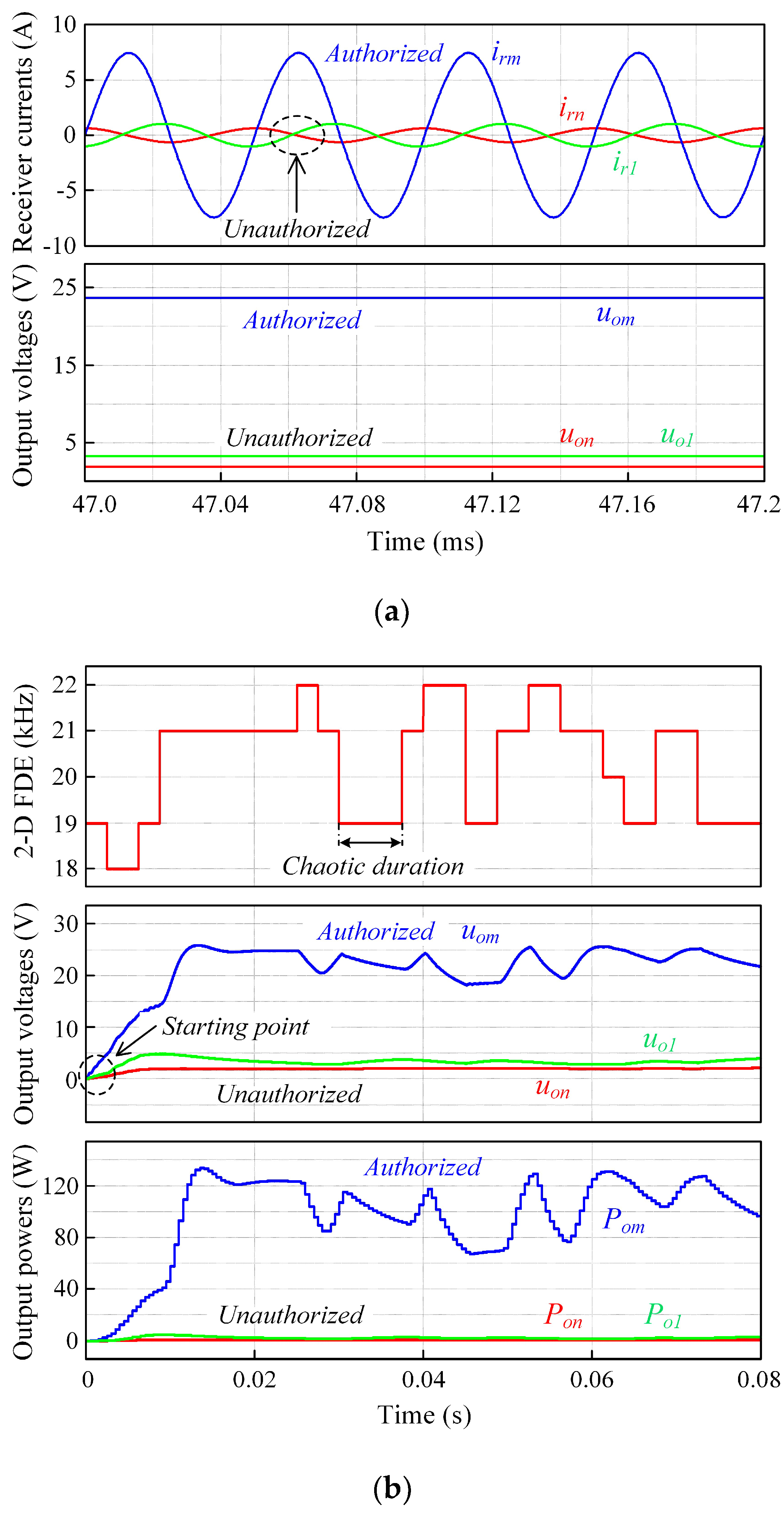
4. Computational Simulation

To assess the energy security performance of the proposed continuously energy-encrypted WPT system, finite element analysis (FEA) and system simulation are performed. The key design specifications and parameters are listed in Table 1. Detailed geometries with dimensions of the transmitter and receiver coils are depicted in Figure 5, where the transmitter and receiver coils respectively adopt a two-layer and three-layer configurations to enhance their mutual inductances, hence improving the transmission efficiency. The transmission distance is 130 mm and each receiver coil can be separately authorized to decrypt and pick up the encrypted wireless power.
By using FEA, Figure 6 shows the decreasing trend of coupling coefficient with the increasing vertical transfer distance between the transmitter and central (or lateral) authorized receiver. Also, the magnetic field distributions are shown in Figure 7 in which only the central receiver coil is authorized, or only the right lateral receiver coil is authorized. As shown in Figure 7a,b, the magnetic flux pipe can be effectively built up by using the energy encryption scheme. It can be observed that the vast majority of magnetic flux lines are bundled up through the authorized receiver coil, and only insignificant ones are dispersed through the unauthorized receiver coils. Figure 7a,b also demonstrate that the current densities in the authorized receiver coil are much larger than those in the unauthorized ones. Therefore, only the authorized receiver can successfully decrypt and harvest the encrypted wireless energy, thus inducing large current. Along the vertical plane, the contour plots of the magnetic flux densities are plotted in Figure 7c,d, where the magnetic flux densities around the authorized receivers are far higher than those around the unauthorized ones. Along the middle parallel plane, the 3-D magnetic flux densities are plotted in Figure 7e,f, where the saddle-shape magnetic flux densities under the authorized receiver coil can reach up to 3.044 mT and 2.619 mT, respectively. By applying the proposed continuously energy encryption scheme, Figure 8a shows that both the authorized receiver current and output voltage (23.82 V) are much larger than the unauthorized receiver currents and output voltages (2.01 V and 3.26 V). Figure 8b shows that both the operating frequency and its active duration are simultaneously encrypted in a 2-D scale to improve the energy security performance. With knowledge of security keys, the authorized receiver can always successfully decrypt and pick up the encrypted wireless power, thus generating an average output voltage of 22.75 V, while the unauthorized receivers fail to decrypt and harvest from the proposed energy-encrypted WPT system, hence only generating insignificant values of 2.27 V and 3.28 V. Correspondingly, the wireless power harvested by the authorized receiver is 104.57 W, far greater than those (0.83 W and 2.16 W) harvested by the unauthorized ones. During the first 0.08 s, an energy of 8.37 J is transferred to the authorized receiver, whereas only 0.239 J is transferred to the unauthorized ones, corresponding to 2.78% of the total energy transfer.

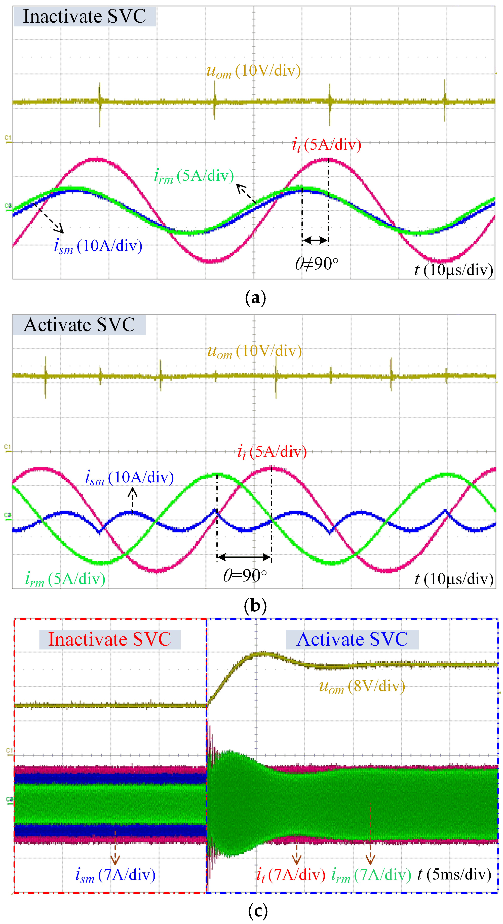
5. Experimental Verification

To verify the feasibility of the proposed continuously energy-encrypted SVC-based WPT system, an exemplified prototype is built for experimental tests as shown in Figure 9. When the encrypted operating frequency deviates the resonant frequency, Figure 10a shows the measured waveforms of the transmitter current it, SVC inactive current ism, authorized receiver current irm and output voltage uom in the state of inactivating SVC. It can be observed that the leading angle θ does not exactly equal π/2, and the output voltage uom of the authorized receiver, as well as its harvested wireless power, is low. After activating the SVC in Figure 10b, the leading angle θ is pulled back to π/2, and both the output voltage uom and the harvested wireless power of the authorized receiver are effectively increased. Thus, the energy-encrypted WPT system reenters into a resonance state by adjusting the SVC-based impedance compensation. To demonstrate the dynamic response of the proposed SVC-based decryption, Figure 10c shows the measured waveforms of the proposed energy-encrypted WPT system operating from the inactivation to the activation of SVC. The increased output voltage of the authorized receiver effectively verifies the feasibility of the proposed SVC.
After activating the proposed SVC for energy decryption, Figure 11a shows measured waveforms of the input voltage uin, encrypted transmitter current it, authorized receiver current irm and unauthorized receiver current ir1. It can be observed that the authorized receiver current irm (5.43 A) is much larger than the unauthorized one (0.601 A). As shown in Figure 11b, the output voltage uom (25.57 V) of the authorized receiver is far larger than the output voltages uo1 and uon (3.71 V and 1.30 V) of the unauthorized ones. Thus, the wireless power harvested by the authorized receiver can reach up to 130.76 W, while those harvested by the unauthorized receivers are suppressed to insignificant values of 2.75 W and 0.39 W, corresponding to 2.35% of the total power transfer. By directly introducing the chaotic 2-D FDE technology, Figure 11c shows the encryption performance of the proposed continuously energy-encrypted SVC-based WPT system. Notedly, both the fluctuations and their widths on the output voltages indicate that the proposed 2-D FDE scheme is effective by flexibly encrypting the operating frequency and its duration in a 2-D scale. It can be found that the average output voltage uom of the authorized receiver can achieve 22.49 V, whereas the output voltages uo1 and uon of the unauthorized ones are insignificant, only 2.98 V and 1.50 V, respectively. Correspondingly, the authorized receiver can decrypt and pick up the encrypted wireless power of 101.16 W, while the unauthorized receiver’s performance is greatly suppressed with harvested wireless powers of 1.78 W and 0.45 W, respectively. Thus, the authorized receiver can successfully harvest 97.84% of wireless powers among all the receivers. It confirms that the MEBT and chaotic 2-D FDE can generate a sequence of dynamic security keys to guarantee energy security. Thus, the proposed continuously energy-encrypted SVC-based WPT system is well verified to improve the energy security performance for multi-receiver WPT systems.

6. Conclusions

A novel continuously variable-frequency energy-encrypted WPT system using SVC has been proposed and then implemented, which can significantly improve the wireless energy security. The proposed LCC-compensated switched-capacitorless transmitter can continuously encrypt the wireless energy into theft-proof energy packages, while the presented SVC successfully facilitates only authorized receivers to decrypt and harvest the encoded energy packages. By directly introducing a chaotic 2-D FDE technology, a sequence of highly defensive security keys is generated to greatly enhance energy security performance. With knowledge of security keys, the authorized receiver can successfully harvest 97.84% of wireless powers among all the receivers, while the unauthorized ones pick up only insignificant wireless powers from the proposed energy-encrypted WPT system. The feasibility of the proposed continuously variable-frequency energy-encrypted WPT system using LCC-compensated switched-capacitorless transmitter and SVC has been effectively verified by theoretical analysis, simulation and experimentation.

Author Contributions

W.L., K.T.C. and W.H.L. developed the idea, carried out the analysis, performed the verification and wrote this paper. Z.Z. made important suggestions.

Funding

This research was funded by the Hong Kong Research Grants Council, Hong Kong Special Administrative Region, China, grant number 17204317.

Conflicts of Interest

The authors declare no conflict of interest.

Appendix A

η k = λ k i r k 2 R L k _ eq U in i in Re Z in / Z in = λ k ω m L t r k 2 R L k _ eq i in Z C Z r k Z C + Z t _ total 2 i in Z in · i in Re Z in Z in = λ k R L k _ eq ω m L t r k 2 Z C 2 Re Z in Z r k Z t _ total + Z C 2 = λ k R L k _ eq ω m L t r k 2 Z r k 2 1 j ω m C C 2 Re R C + j ω m L C + Z r e f + R t + j ω m L t + 1 j ω m C t 1 j ω m C C Z ref + R t + j ω m L t + 1 j ω m C t + 1 j ω m C C · Z ref + R t + j ω m L t + 1 j ω m C t + 1 j ω m C C 2 = λ k R L k _ eq L t r k 2 Z r k 2 C 1 2 R C + Re Re k = 1 n λ k Z ref k + j · Im k = 1 n λ k Z ref k + R t + j ω m L t + 1 j ω m C t 1 j ω m C C Re k = 1 n λ k Z ref k + j · Im k = 1 n λ k Z ref k + R t + j ω m L t + 1 j ω m C t + 1 j ω m C C · Re k = 1 n λ k Z ref k + j · Im k = 1 n λ k Z ref k + R t + j ω m L t + 1 j ω m C t + 1 j ω m C C 2 = λ k R L k _ eq L t r k 2 Z r k 2 C C 2 R C + Re L t C C 1 ω m 2 C t C C + Im k = 1 n λ k Z ref k ω m C j R t r ω m C C R t r + j ω m L t 1 ω m C C 1 ω m C t + Im k = 1 n λ k Z ref k · R t r + j ω m L t 1 ω m C C 1 ω m C t + Im k = 1 n λ k Z ref k 2 = λ k R L k _ eq L t r k 2 Z r k 2 C C 2 R t r 2 + ω m L t 1 ω m C C 1 ω m C t + Im k = 1 n λ k Z ref k 2 × 1 R C + R t r L t C C 1 ω m 2 C t C C + Im k = 1 n λ k Z ref k j ω m C R t r ω m C C ω m L t 1 ω m C C 1 ω m C t + Im k = 1 n λ k Z ref k R t r 2 + ω m L t 1 ω m C C 1 ω m C t + Im k = 1 n λ k Z ref k 2 λ k R L k _ eq L t r k 2 Z r k 2 C C 2 R t r 2 + ω m L t 1 ω m C C 1 ω m C t + Im k = 1 n λ k Z ref k 2 × 1 R C + 1 ω m 2 C C 2 Re k = 1 n λ k Z ref k + R t λ m ω m L t r m 2 R L k _ eq + R r k + R t 2 + ω m L t 1 ω m C C 1 ω m C t + Im k = 1 n λ k Z ref k 2 = λ k R L k _ eq L t r k 2 Z r k 2 C C 2 R C R t r 2 + ω m L t 1 ω m C C 1 ω m C t + Im k = 1 n λ k Z r e f k 2 + 1 ω m 2 C C 2 Re k = 1 n λ k Z ref k + R t = λ k R L k _ eq ( ω m L t r k ) 2 Z r k 2 ( ω m C C ) 2 R C Re k = 1 n λ k ( ω m L t r k ) 2 Z r k + R t 2 + ω m L t 1 ω m C C 1 ω m C t + Im k = 1 , k m n λ k Z ref k 2 + R t r
η m = λ m R L m L t r m 2 R L m _ eq + R r m 2 R C Re k = 1 n λ k Z ref k + R t 2 + ω m L t 1 ω m C C 1 ω m C t + Im k = 1 n λ k Z ref k 2 + 1 ω m 2 C C 2 Re k = 1 n λ k Z ref k + R t = λ m R L m ( ω m L t r m ) 2 R L m _ eq + R r m 2 ( ω m C C ) 2 R C Re k = 1 n λ k ( ω m L t r k ) 2 Z r k + R t 2 + ω m L t 1 ω m C C 1 ω m C t + Im k = 1 , k m n λ k Z ref k 2 + R t r = η m = λ m R L m ( ω m L t r m ) 2 R L m _ eq + R r m 2 ( ω m C C ) 2 R C Re k = 1 n λ k ( ω m L t r k ) 2 Z r k + R t 2 + ω m L t 1 ω m C C 1 ω m C t + Im k = 1 , k m n λ k Z ref k 2 + R t r λ m R L _ eq ( ω m L t r ) 2 R L m _ eq + R r m 2 ( ω m C C ) 2 R C Z 1 2 + Z 2 2 + λ m ( ω m L t r ) 2 R r m + R L m _ eq + k = 1 , k m n λ k ( ω m L t r k ) 2 R r k + R L k _ eq ω m L r 1 ω m C r 2 + R t λ m R L m ( ω m L t r m ) 2 R L m _ eq + R r m 2 ( ω m C C ) 2 R C λ m ( ω m L t r m ) 2 R r m + R L m _ eq 2 + Z 2 2 + λ m ( ω m L t r m ) 2 R r m + R L m _ eq = λ m R L m ( ω m L t r m ) 2 R L m _ eq + R r m 2 1 ( ω m C C ) 2 R C T t r 2 + T t c 2 + T t r
where Z 1 = λ m ( ω m L t r ) 2 R r m + R L m _ eq + k = 1 , k m n λ k ( ω m L t r k ) 2 R r k + R L k _ eq ω m L r 1 ω m C r 2 + R t Z 2 = ω m L t 1 ω m C t 1 ω m C C + k = 1 , k m n λ k ( ω m L t r k ) 2 1 ω m C r k ω m L r k ( R r k + R L k _ eq ) 2 + ω m L r k 1 ω m C r k 2 .

References

  1. Tesla, N. Apparatus for Transmitting Electrical Energy. U.S. Patent 119 732, 1 December 1914. [Google Scholar]
  2. Covic, G.A.; Boys, J.T. Inductive power transfer. Proc. IEEE 2013, 101, 1276–1289. [Google Scholar] [CrossRef]
  3. Jiang, C.; Chau, K.T.; Liu, C.; Lee, C.H.T. An overview of resonant circuits for wireless power transfer. Energies 2017, 10, 894. [Google Scholar] [CrossRef]
  4. Mi, C.C.; Buja, G.; Choi, S.Y.; Rim, C.T. Modern advances in wireless power transfer systems for roadway powered electric vehicles. IEEE Trans. Ind. Electron. 2016, 63, 6533–6545. [Google Scholar] [CrossRef]
  5. Han, W.; Chau, K.T.; Zhang, Z. Flexible induction heating using magnetic resonant coupling. IEEE Trans. Ind. Electron. 2017, 64, 1982–1992. [Google Scholar] [CrossRef]
  6. Jiang, C.; Chau, K.T.; Leung, Y.; Liu, C.; Lee, C.H.T.; Han, W. Design and analysis of wireless ballastless fluorescent lighting. IEEE Trans. Ind. Electron. 2019, 66, 4065–4074. [Google Scholar] [CrossRef]
  7. Liu, W.; Chau, K.T.; Lee, C.H.T.; Jiang, C.; Han, W.; Lam, W.H. Multi-frequency multi-power one-to-many wireless power transfer system. IEEE Trans. Magn. 2019. [Google Scholar] [CrossRef]
  8. Zhu, Q.; Wang, L.; Guo, Y.; Liao, C.; Li, F. Applying LCC compensation network to dynamic wireless EV charging system. IEEE Trans. Ind. Electron. 2016, 63, 6557–6567. [Google Scholar] [CrossRef]
  9. Liu, W.; Chau, K.T.; Lee, C.H.T.; Jiang, C.; Han, W. A switched-capacitorless energy-encrypted transmitter for roadway-charging electric vehicles. IEEE Trans. Magn. 2018, 54, 1–6. [Google Scholar]
  10. Choi, S.Y.; Gu, B.W.; Jeong, S.Y.; Rim, C.T. Advances in wireless power transfer systems for roadway-powered electric vehicles. IEEE Trans. Emerg. Sel. Top. Power Electron. 2015, 3, 18–36. [Google Scholar] [CrossRef]
  11. Jiang, C.; Chau, K.T.; Liu, C.; Han, W. Wireless DC motor drives with selectability and controllability. Energies 2017, 10, 49. [Google Scholar] [CrossRef]
  12. Sato, M.; Yamamoto, G.; Gunji, D.; Imura, T.; Fujimoto, H. Development of wireless in-wheel motor using magnetic resonance coupling. IEEE Trans. Power Electron. 2016, 31, 5270–5278. [Google Scholar] [CrossRef]
  13. Zhang, Z.; Chau, K.T.; Qiu, C.; Liu, C. Energy encryption for wireless power transfer. IEEE Trans. Power Electron. 2015, 30, 5237–5246. [Google Scholar] [CrossRef]
  14. Zhang, Z.; Chau, K.T.; Liu, C.; Qiu, C.; Lin, F. An efficient wireless power transfer system with security considerations for electric vehicle applications. J. Appl. Phys. 2014, 115, 1–3. [Google Scholar] [CrossRef]
  15. Kurs, A.; Karalis, A.; Moffatt, R.; Joannopoulos, J.D.; Fisher, P.; Soljačić, M. Wireless power transfer via strongly coupled magnetic resonances. Science 2007, 317, 84–86. [Google Scholar] [CrossRef] [PubMed]
  16. Zhang, Y.; Lu, T.; Zhao, Z.; He, F.; Chen, K.; Yuan, L. Selective wireless power transfer to multiple loads using receivers of different resonant frequencies. IEEE Trans. Power Electron. 2015, 30, 6001–6005. [Google Scholar] [CrossRef]
  17. Tian, J.; Hu, A.P. A DC-voltage-controlled variable capacitor for stabilizing the ZVS frequency of a resonant converter for wireless power transfer. IEEE Trans. Power Electron. 2017, 32, 2312–2318. [Google Scholar] [CrossRef]
  18. Liu, W.; Zhang, J.; Chen, R. Modelling and control of a novel zero-current-switching inverter with sinusoidal current output. IET Power Electron. 2016, 9, 2205–2215. [Google Scholar] [CrossRef]
  19. Zhong, Q.C.; Zeng, Y. Control of inverters via a virtual capacitor to achieve capacitive output impedance. IEEE Trans. Power Electron. 2014, 29, 5568–5578. [Google Scholar] [CrossRef]
  20. Chen, X.; Hou, Y.; Tan, S.C.; Lee, C.K.; Hui, S.Y.R. Mitigating voltage and frequency fluctuation in microgrids using electric springs. IEEE Trans. Smart Grid. 2015, 6, 508–515. [Google Scholar] [CrossRef]
  21. Liu, Y.; Wang, X.; Peng, F.Z. An H-bridge-based single-phase var generator with minimum DC capacitance. IEEE J. Emerg. Sel. Top. Power Electron. 2018, 6, 2001–2014. [Google Scholar] [CrossRef]
  22. Ann, S.; Lee, W.-Y.; Choe, G.-Y.; Lee, B.K. Integrated control strategy for inductive power transfer systems with primary-side LCC network for load-average efficiency improvement. Energies 2019, 12, 312. [Google Scholar] [CrossRef]
  23. Yan, Z.; Zhang, Y.; Song, B.; Zhang, K.; Kan, T.; Mi, C. An LCC-P compensated wireless power transfer system with a constant current output and reduced receiver size. Energies 2019, 12, 172. [Google Scholar] [CrossRef]
  24. Liu, X.; Clare, L.; Yuan, X.; Wang, C.; Liu, J. A design method for making an LCC compensation two-coil wireless power transfer system more energy efficient than an SS counterpart. Energies 2017, 10, 1346. [Google Scholar] [CrossRef]
  25. Chau, K.T.; Wang, Z. Chaos in Electric Drive Systems—Analysis, Control. and Application; Wiley-IEEE Press: New York, NY, USA, 2011. [Google Scholar]
  26. Hénon, M. A two-dimensional mapping with a strange attractor. Comm. Math. Phys. 1976, 50, 69–77. [Google Scholar] [CrossRef]
  27. Chuan, B.T.; Kato, M.; Imura, T.; Sehoon, O.; Hori, Y. Automated impedance matching system for robust wireless power transfer via magnetic resonance coupling. IEEE Trans. Ind. Electron. 2013, 60, 3689–3698. [Google Scholar]
  28. Lim, Y.; Tang, H.; Lim, S.; Park, J. An adaptive impedance-matching network based on a novel capacitor matrix for wireless power transfer. IEEE Trans. Power Electron. 2014, 29, 4403–4413. [Google Scholar] [CrossRef]
Figure 1. Proposed continuously variable-frequency energy-encrypted WPT system using proposed LCC-compensated switched-capacitorless transmitter and SVC.
Energies 12 01286 g001
Figure 2. Proposed chaotic 2-D FDE algorism. (a) Flowchart; and (b) 2-D Hénon map.
Energies 12 01286 g002
Figure 3. Phasor diagram of proposed SVC.
Energies 12 01286 g003
Figure 4. Block diagram of proposed SVC.
Energies 12 01286 g004
Figure 5. Geometries of transmitter and receiver coils. (a) Transmitter coil; (b) receiver coil; and (c) displacement between transmitter and receiver coils.
Energies 12 01286 g005aEnergies 12 01286 g005b
Figure 6. Coupling coefficients versus vertical transfer distance between transmitter and receivers.
Energies 12 01286 g006
Figure 7. Magnetic field distributions. (a) Flux lines and current densities (central coil authorized); (b) flux lines and current densities (lateral coil authorized); (c) flux densities along vertical plane (central coil authorized); (d) flux densities along vertical plane (lateral coil authorized); (e) 3-D flux densities (central coil authorized); and (f) 3-D flux densities (lateral coil authorized).
Energies 12 01286 g007aEnergies 12 01286 g007b
Figure 8. Simulation characteristics of proposed LCC-compensated FDE-WPT system using SVC. (a) Authorized and unauthorized receiver currents; and (b) energy security performance.
Energies 12 01286 g008
Figure 9. Experimental setup.
Energies 12 01286 g009
Figure 10. Measured waveforms of proposed SVC-based energy-encrypted WPT system. (a) Inactivate SVC (θ > 90°); (b) activate SVC (θ = 90°); and (c) dynamic response.
Energies 12 01286 g010
Figure 11. Experimental performances of proposed continuously variable-frequency energy-encrypted WPT system using LCC-compensated switched-capacitorless transmitter and SVC. (a) Input voltage and resonant currents; (b) output voltages and authorized receiver current; and (c) energy security performance using chaotic 2-D FDE.
Energies 12 01286 g011aEnergies 12 01286 g011b
Table 1. Design specifications and parameters.
ItemsValue
Digital signal processerTMS320F28335
Transmitter compensated inductance (Lf)150 μH
Transmitter compensated capacitance (Cf)250 nF
Transmitter capacitance (Ct)100 nF
Transmitter coil inductance (Lt)566.80 μH
Transmitter coil turns (nt)20 (2 layers)
Transmitter coil internal resistance (Rt)0.3 Ω
Receiver capacitances (Crk)81.43, 185.23, 850.00 nF
Receiver coil inductances (Lr1, Lrm, Lrn)345.65, 355.30, 348.63 μH
Receiver coil turns (nrk)30 (3 layers)
Receiver coil internal resistance (Rrk)0.2 Ω
Mutual inductances (Ltr1, Ltrm, Ltrn)26.72, 33.11, 28.59 μH
SVC AC inductance (Lsk)10 μH
SVC AC capacitance (Csk)2 μF
Output filter capacitance (Co)2000 μF

