Novel Design of Primary Optical Elements Based on a Linear Fresnel Lens for Concentrator Photovoltaic Technology


1
Department of Information and Communication Engineering, Myongji University, Gyeonggi-do 17058, Korea
2
Institute of Applied Material Science, Vietnam Academy of Science and Technology, Ho Chi Minh City 70072, Vietnam
3
Electrical and Electronics Engineering, Phenikaa University, Hanoi 1000, Vietnam
*
Authors to whom correspondence should be addressed.
Energies 2019, 12(7), 1209; https://doi.org/10.3390/en12071209
Submission received: 5 March 2019
/
Revised: 20 March 2019
/
Accepted: 22 March 2019
/
Published: 28 March 2019
(This article belongs to the Special Issue Research on Solar Collector)
Abstract
:In this paper, we present a design and optical simulation of a novel linear Fresnel lens. The lens can be applied to a concentrator photovoltaic (CPV) system as a primary optical element (POE) to increase the concentration ratio and improve the uniformity of irradiance distribution over the receiver. In addition, the CPV system can use the proposed lens as a concentrator without involving a secondary optical element (SOE). The designed lens, which is a combination of two linear Fresnel lenses placed perpendicular to each other, can collect and distribute the direct sunlight on two dimensions. The lens is first designed in the MATLAB program, based on the edge ray theorem, Snell’s law, and the conservation of the optical path length, and then drawn in three dimensions (3D) by using LightToolsTM. Furthermore, in order to optimize the structure and investigate the performance of the lens, the ray tracing and the simulation are also performed in LightToolsTM. The results show that the newly designed lens can achieve a high concentration ratio of 576 times, a high optical efficiency of 82.4%, an acceptable tolerance of 0.84°, and high uniform irradiance of around 77% for both horizontal and vertical investigation lines over the receiver.
1. Introduction
In recent years, the development of photovoltaic technology has brought about significant improvement in the efficiency of solar cells. The latest record of direct conversion of sunlight into electricity of multi-junction solar cells reaches 46%, as published by the Fraunhofer Institute, Germany [1]. Therefore, solar energy [2,3,4] becomes a promising resource to completely replace fossil energy in the future. However, the high cost of multi-junction solar cells [5,6,7] leads to the price of the photovoltaic system being high. An effective way to reduce the cost per watt value is to cut down the size of the required cell area by using a cheaper optical system in concentrator photovoltaic (CPV) technology.
The CPV [8,9,10,11] is a potential technology to promote the popularity of solar energy by reducing the cost of the photovoltaic system [12]. Generally, the CPV consists of an optical part and multi-junction solar cells with high efficiency. The optical part operates as a concentrator to converge sunlight in a large area to a small receiver (multi-junction solar cells). The concentrator used in CPV is usually a mirror or a lens [13,14,15]. The most popular lens used in CPV system is the Fresnel lens, due to its compactness, low cost with high transparency, and availability for a high concentration ratio.
The Fresnel lens [16,17,18] used in CPV systems can be a linear Fresnel lens or a regular Fresnel lens (just called Fresnel lens) with circular grooves. In the framework of CPV technology, the Fresnel lens is applicable for a high concentration ratio (> 100 times) while the linear Fresnel lens is suitable to aim at a regular or low concentration ratio [19]. The Fresnel lens can focus the sunlight on two dimensions so that it easily reaches a high concentration ratio. Therefore, it is usually applied to CPV systems using high-efficiency multi-junction solar cells. On the other hand, the linear Fresnel lens is enabled only to focus the sunlight on one dimension, so it is normally used for solar thermal technology [20,21,22].
The Fresnel lens has been widely used as a primary optical component (POE) in CPV systems. However, a natural property of the Fresnel lens is that it always creates a hot spot in the center of the solar cell [23,24,25]. Thus, it distributes the sunlight over the receiver in a non-uniform manner, which reduce the efficiency of the solar cell. In addition, solar cells exposed to non-uniform irradiance distribution with a hot spot in the center can be degraded quickly by a high thermal effect if the cooling system is not good enough.
An effective way to improve the uniformity of irradiance over the solar cells is to use a combination consisting of a primary optical element (POE) and a secondary optical element (SOE) component [26,27,28]. Generally, the SOE has two functions in the optical part of the CPV system. Firstly, it helps to redistribute the sunlight over the receiver to improve the uniformity of irradiance distribution. Secondly, it helps to increase the sunlight tracking tolerance in the CPV system. Therefore, the combination of POE and SOE is the normal choice for the CPV system. The SOE usually has to operate under harsh conditions with high irradiance and high temperatures, demanding that its design and properties are of high quality to ensure its lifetime is equal to that of the CPV system [29,30].
In CPV technology, the optical system, consisting of the POE and the SOE, accounts for from 12% to 18% of the total system cost, in which the SOE cost is about 25–45% of the optical part depending on the concentration level (number of SOEs/m2), the material of the SOE, and the technology [31,32,33,34,35]. Assume that a module carries 100 SOEs per square meter (in a geometry concentration ratio around 1000 times and solar cells size 1 cm2), about 370,000 SOEs per MWp are needed under 30% module efficiency and 900 W/m2 irradiances for concentration standard operating conditions [36], which is a huge number of SOEs. Therefore, it is undoubtedly economically efficient to have a CPV system that can work without employing SOEs. Several efforts have been made to design an optical CPV system without an SOE. Zhuang et al. [37] designed a hybrid Fresnel lens for generating uniform irradiance. In the research, the Fresnel lens with high concentration consists of two parts. The center part of the lens is designed based on refraction phenomena, while the outer area is designed based on internal reflection phenomena. Languy et al. [24] introduced a method to deal with chromatic aberration, in which the Fresnel lens grooves are made by polymethyl methacrylate and polycarbonate to enhance the concentration and achieve the spectrally uniform flux on the receiver. Leutz et al. [38] proposed a non-imaging Fresnel lens that had an improvement in the acceptance angle by using the edge ray principle method. Gonzalez et al. [39] used the Simultaneous Multiple Surface (SMS) method to increase the acceptance angle of the linear Fresnel lens. In the study, the lens has a small concentration ratio (less than 100 times), so it is suitable for low CPV systems (LCPV). In addition, there are many more research studies to design optical systems for CPV systems without SOEs, such as Noburo et al. [40], Akisawa et al. [41], Ryu et al. [42], etc. Although there are many studies on designing the concentrator of the CPV system by modifying the Fresnel lens [43,44,45], several disadvantages still need to be resolved.
In this paper, we propose a novel design of the linear Fresnel lens, which is able to collect and distribute the sunlight on two dimensions over the receiver. The lens structure consists of two faces: the upper groove surface and the lower groove surface, which are linear Fresnel lenses arranged perpendicular to each other. Each linear lens focuses sunlight on one dimension so that the whole novel lens, consisting of two linear Fresnel lenses, will focus sunlight on two dimensions. The linear Fresnel lenses used as upper and lower surfaces are designed by using the conservation of the optical path length and the edge ray theorem. The shape of the newly designed lens is constructed in the MATLAB program. The data from MATLAB are then applied to LightToolsTM software to draw the lens in three dimensions (3D). The ray tracing is used to optimize the lens structure. The simulation is performed to estimate the efficiency of the novel lens, which works as a concentrator in the CPV system.
The remainder of the paper is organized as follows: in Section 2, the basic idea of the design of the newly linear Fresnel lens is indicated. Section 3 describes in detail the process of building the grooves of the upper surface, while Section 4 demonstrates the construction procedure for the grooves of the lower surface. Section 5 presents the simulation results and discussion. Finally, the brief concluding remarks and future work are included in Section 6.
2. The Basic Idea
The conventional structure of the linear Fresnel lens consists of a series of linear grooves that act as individual refracting surfaces bending parallel light rays into a common focal line. In the structure, the lens collects and distributes sunlight on one dimension, so the lens usually has a small or regular geometry concentration ratio (smaller than 100 times). To increase the concentration level, the series of the grooves is revolved around an axis that is orthogonal to the lens at the center instead of extruding along an axis orthogonal to a cross-section of the grooves in the linear Fresnel lens. Figure 1 shows the way to build two kinds of Fresnel lenses, distributing sunlight on one or two dimensions. By revolving the grooves around an axis, the Fresnel lens can easily achieve a high concentration ratio. However, this structure type always distributes sunlight non-uniformly over the receiver leading to the appearance of a hot spot that negatively affects the efficiency and the lifetime of the multi-junction solar cells. A new idea is proposed to overcome these issues, in which a combination of two linear Fresnel lenses placed perpendicular to each other is presented. Figure 2 shows the basic structure of the novel linear Fresnel lens.
The lens shape is constructed in the MATLAB program with the flowchart of design process shown in Figure 3. In the process, initial parameters must be chosen to build the lens. The initial parameters can be receiver size, distance between lens and receiver, size of grooves, geometry concentration ratio target, etc. Based on these parameters, the lens is constructed step by step from the center to the edge of the lens or vice versa, and from the upper surface to the lower surface. In addition, the structure of the lens has to be optimized to get a uniform irradiance distribution over the receiver. Such a challenge can be overcome by using a design with multi-focal points instead of a design with only one focal point, as in the case in the conventional design. In the novel design, each groove has its own focal point to distribute the sunlight uniformly over the receiver, leading to the whole lens being able to distribute the sunlight uniformly over the target area. Therefore, the estimation of focal point positions is important to obtain uniform irradiance distribution. The technique to estimate the positions of focal points is changed slightly in the design of the upper and the lower surfaces that will be described in detail in following sections.
Generally, direct sunlight is not perfect parallel so that the direct sunlight comes to the Earth surface with an angle about 0.265°, namely angular aperture of sunlight or solar angle [43]. As a result, the bundle of direct sunlight comes to every point of Fresnel lens under angle 0.265° with cone shape as example in Figure 4. However, it is much simpler to design the lens if we just use normal incident. Therefore, in this paper, the novel lens is designed by using the normal incidents.
In this study, the novel linear Fresnel lens is designed by using a combination of Snell’s law, conservation of pathlength, and the edge ray principle. The edge ray principle is defined as a design method, in which the light rays coming from the edges of the source are redirected towards the edges of the receiver, this will ensure that all light rays coming from the inner points in the source will end up on the receiver. In this method, the image does not need to form, the only goal is to transfer the light from the source to the target. Edge ray principle is illustrated in Figure 5.
Based on the edge ray principle, the ray coming to the edge of the designed Fresnel lens should be redirected to reach the extreme point of the receiver [46]. However, in our design, the novel linear Fresnel lens comprises two grove surfaces: the upper surface and lower surface, in which they are placed perpendicular to each other. Each groove surface consists of some grooves, which play main role to guide the direct sunlight to the receiver. To build the novel lens, we tried to design groove by groove. Each groove is designed by using Snell’s law, the conservation of pathlength, and edge ray principle. Therefore, the bundle of rays coming to each groove consists of left edge ray and right edge ray that come to the groove at left edge point and right edge point of groove, respectively. Additionally, every ray between the left edge ray and right edge ray should be come to somewhere on the receiver. In another word, each groove plays role as a mini lens so that we can use the edge ray principle to design every groove. When the design process for one groove has been completed, the same procedure is repeated to build the next groove. The edge ray principle applied to design one groove is illustrated in Figure 6, in which the left edge ray, the right edge ray, and an example of ray between left and right edge rays are shown.
Figure 7 and Figure 8 show the difference between the conventional distribution and the new technique for sunlight distribution. In the new technique, the bundle of sunlight coming over one groove has the left and the right edge rays that go to the left and the right extreme sides of the receiver, respectively. The left and the right edge rays intersect with each other at an unreal point F (Figure 8), which can be either beneath the receiver or above the groove, depending on the size of the receiver and the groove. If the groove size is smaller than that of the receiver, the intersection point F will be above the groove. Otherwise, the intersection point F will be under the receiver side. Furthermore, the estimation of the focal point of each groove is important. A good focal point can help the bundle of sunlight to be distributed uniformly over the receiver. The bundle of rays coming to one groove is converged at the focal point F so that all the rays can reach the receiver. As a result, the direct sunlight arriving at one groove is distributed uniformly from the left to the right extreme sides of the receiver.
3. Design of the Linear Fresnel Lens as an Upper Groove Surface
The novel linear Fresnel lens is built by a combination of a linear Fresnel lens with an upper groove surface, namely upper surface, and a linear Fresnel lens with a lower groove surface, namely lower surface. The task of the two surfaces is to distribute the direct sunlight. Each surface focuses the sunlight on one dimension (on a focal line). However, when two surfaces are placed perpendicular to each other to become a new structure, the lens will focus the sunlight on two dimensions. As a result, although the linear Fresnel lenses are used to collect the sunlight, a high concentration ratio can be achieved by the proposed structure. In this section, the design of the upper surface is described in detail.
In the proposed design, each groove is designed to distribute the sunlight uniformly over the half or the whole of the receiver (Figure 9) because of the symmetry of the structures of the lens and the receiver. In addition, the size of the grooves is chosen to be bigger than that of the receiver, thus the focal point of each groove lies beneath the receiver. In Figure 9, each groove is constructed by the Cartesian surface S1 as input and the flat surface S2 as output. The bundle of rays coming to one groove is refracted at the input surface and then exits the lens at the output surface. Finally, the bundle of rays converges at the focal point of the groove, in which the left edge ray reaches the left extreme point X1 of the receiver while the right edge ray passes through the receiver center I0. After that, two edge rays intersect with each other at the focal point F of the groove. All rays that lie between the left and the right edge rays also converge at the focal point F due to the conservation of optical path length. As a result, all rays of the bundle coming to one groove reach the left- or the right-half of the receiver, depending on the groove position. The design procedure of one groove is described with reference to Figure 9 as follows:
Step 1: Initialize parameters such as the width of the output beam w, the thickness of the lens d, the position of points P0 and P1, the height of the lens, etc. The width of the output beam w is defined as the distance between the left and the right edge rays that exit from the output surface S2.
Step 2: The left edge ray coming to the point P1 is first refracted by angle β1 and then approach surface S2 at P2. After that, the ray is refracted again by angle β2 and finally reaches the extreme point X1 of the receiver. Because the position of P1 is known in advance, the position of P2 can be calculated as follows:
where X1 is the position of the left extreme point of the receiver, n is the refractive index of the lens, xP0, yP0, yP1, xP2 are the positions of P0, P1, P2 on the x-axis and the y-axis, respectively, β1 and β2 are the refractive angles of the left edge ray at the input surface S1 and the output surface S2, respectively.
Step 3: In this design, P3 is the limit point of the surface S1, which is a Cartesian oval surface, so it is difficult to find out the position of the point P3. In contrast, the point P5 is on the exit surface S2, which is a flat surface, so it is easy to estimate the position of P5 by using the position of P2 and the width of output beam w as Equation (4). Therefore, the position of P5 is calculated before estimating the position of P3. In addition, the position of P5 on the y-axis is equal to the height of the lens, thus the position of P5 can be estimated totally as follows:
Step 4: Depending on the size of the receiver and the grooves, the left and the right edge rays can intersect with each other at the position beneath the receiver or above the groove. In this study, we assume that the size of the groove is bigger than that of the receiver, thus the intersection position is beneath the receiver. The position of the focal point F, which is also the intersection point of the left and the right edge rays, can be calculated by using straight lines P5I0 and P2X1.
Step 5: On the right edge ray of the groove, the position of P3 can be calculated by using the conservation of the optical path length and Snell’s law. The right edge ray coming to the groove at the surface S1 is refracted by angle α1 and then refracted again by angle α2 at the surface S2 to approach the receiver center. Therefore, the position of P3 can be calculated by using the equations as follows:
where xP3, yP3, xP5, and yP5 are the positions of P3 and P5 on the x-axis and the y-axis, a1, a2, and a3 are optical path lengths of the left edge ray, b1 and b2 are the optical path lengths of the right edge ray.
Step 6: All rays arriving at the groove between P1 and P3 have to focus on the focal point F of the groove. Furthermore, they also have to satisfy the conditions in Step 5. Therefore, choosing one point on the surface S2 helps to find out one corresponding point on the surface S1 by using the conditions in Step 5. As a result, the input surface S1 can be built completely by using a large number of rays between two edge rays in this step.
Step 7: In this design, P4 can be calculated by using the lens thickness d and the condition of P4 lying on the straight line P3P5. When the design process for one groove is finished, the same procedure is repeated to build the next groove and so on until the size of the lens is reached. In the new process, P4 in the current groove will be P1 in the next one.
In brief, this section has described the procedure to design the upper surface of the novel linear Fresnel lens in detail, in which each groove designed in seven steps is defined by critical points P0, P1, P2, P3, P4, and P5 and two surfaces S1, and S2.
4. Design of the Linear Fresnel Lens as a Lower Groove Surface
In a similar way to the design of the upper surface, each groove of the Fresnel lens as the lower groove surface is constructed based on the refraction phenomena, the edge ray theorem, and the conservation of the optical path length. However, the structure of the grooves in the lower surface is different from the structure of the grooves in the case of the upper surface. Each lower groove consists of an input surface, which is flat, and an output surface, which is a Cartesian oval surface. Therefore, the sunlight distribution is also slightly different. The bundle of rays coming to one groove is refracted only one time at the output surface to travel to the receiver. The left edge ray has to reach the left extreme point of the receiver while the right edge ray has to pass through the center of the receiver. After that, the left edge ray intersects with the right edge rays at the focal point of the groove, which is an unreal point beneath the receiver. According to the conservation of the optical path length, all rays between the two edge rays are refracted at the output surface to converge at the focal point of the groove so that all the rays reach the receiver. In this way, the sunlight is distributed uniformly over the receiver by one groove. All the grooves distribute sunlight uniformly so that the whole lens also distributes sunlight uniformly. In this design, the structure of the output surface is important to get uniform irradiance distribution over the receiver. The design process of one groove is described in detail with reference to Figure 10 as follows:
Step 1: Initialize parameters such as the width groove, the lens thickness, the size of the receiver, the height of the lens, etc. Furthermore, the positions of P1, P2, P3, and P4 are known in advance by using the value of the width groove w and the lens thickness d in Figure 10. Therefore, the work remaining is to find out the position of P5 and then estimate the Cartesian oval surface S2.
Step 2: The left edge ray of the ray bundle comes to the groove at P1. Because the input surface S1 of the groove is a flat surface, the left edge ray approaches P2 without any refraction. At the P2 position, the left edge ray is refracted to travel to the left extreme point X1 of the receiver. By using this condition, the normal vector at P2 is calculated using the equations as follows:
where n is the refractive index, β1 and β2 are the refractive angles of the left edge ray at the exit surface S2, xP2 and yP2 are the positions of P2 on the x-axis and the y-axis, respectively.
Step 3: The position of P5 is estimated by using two conditions. Firstly, the right edge ray, which exits the groove at P5, has to approach the center I0 of the receiver and then intersects with the left edge ray at the focal point F of the groove. Secondly, the optical path length of the left edge ray has to be equal to that of the right edge ray. Therefore, the position of P5 is calculated by using the following equations:
where I0 is the center of the receiver, α1 is the refractive angle of the right edge ray at P5, xP5 and yP5 are the positions of P5 on the x-axis and the y-axis, a1, a2, b1, and b2 are the optical path lengths of the left and the right edge rays, respectively.
Step 4: All rays between the left and the right edge rays have to converge on the focal point F due to the conservation of the optical path length. In this way, the bundle of rays coming to the groove can be distributed uniformly over the half of the receiver from the center I0 to the extreme point X1. By using individual rays coming to the input surface S1 between the left and the right edge rays, the corresponding exit points at the output surface S2 can be calculated based on the condition of the optical path length. Therefore, the output surface S2 can be built by calculating the output points of a large number of individual rays between the left and the right edge rays.
Step 5: When the design process for one groove has been completed, the same procedure is repeated to build the next groove. In the new process, P3 and P4 in the current groove will be P1 and P2 in the next one, respectively.
In conclusion, this section has described in detail the design process of the lower surface of the novel lens. The lower surface consists of a series of grooves that focus sunlight onto multi-focal points to improve the uniformity of irradiance distribution over the receiver. Each groove is constructed from a flat input surface and a Cartesian oval output surface.
5. Performance and Discussion
In this study, the novel designed lens is applied to CPV technology with the goal of increasing the performance and decreasing the cost of the photovoltaic system. In terms of performance, there are three aspects to improve the CPV system. Firstly, the optical efficiency can be increased thanks to the performance without a secondary optical element (SOE). Secondly, the new structure helps to distribute the sunlight uniformly over the receiver. Thirdly, the shape of irradiance distribution is a square area which brings about a better match with the shape of the solar cells. Furthermore, the cost can be reduced by the improvement of the performance and the simple process to produce the novel Fresnel lens.
The CPV system is built in MATLAB and then simulated in LightToolsTM to estimate the performance of the novel linear Fresnel lens. Parameters are chosen to facilitate application in real conditions. Therefore, a receiver with the size of 10 × 10 mm is chosen to represent a multi-junction solar cell, which usually has a square shape with a width of between 5 mm and 10 mm in commercial products [47]. Moreover, the concentration ratio of CPV using highly efficient multi-junction solar cells has a range of from 300 to 1000 times, depending on the design of the CPV system [10]. Concentrated sunlight can help to increase the efficiency of the solar cells. However, the loss due to the electrode resistance and the series resistance of the solar cells is boosted by the squared function of the photocurrent. As a result, the efficiency of solar cells increases to the maximum value and then decreases regardless of the fact that concentration ratio is still increasing. In the current CPV technology, the optimum concentration ratio can be different and will usually be from 400 to 600 times depending on the quality of the solar cells and the photovoltaic system [48]. Therefore, a size of 240 × 240 mm is chosen for the simulation of the designed lens. With the chosen size, the concentration ratio calculated by the equation is 576 times, where Dlens is the width of the designed lens, and dreceiver is the width of the receiver. These parameters are chosen to be suitable for CPV in the current technology. However, they can be changed easily depending on the aim of the design.
The novel linear Fresnel lens is designed in the MATLAB program and then the data from MATLAB are applied to LighttoolsTM to draw the lens in three dimensions (3D). The ray tracing technique is used to estimate the performance of the design process. Furthermore, the simulation process is also performed using LighttoolsTM to find out the optimum structure and the optical properties of the lens. Table 1 shows the parameters for ray tracing and simulation of the lens in LighttoolsTM.
Figure 11 shows the ray tracing of the linear Fresnel lens using only one groove surface. The sunlight is focused on one dimension as a focal line. However, a combination of these linear Fresnel lens structures can distribute sunlight on two dimensions as indicated in Figure 12.
Besides the structure of the lens shown in Figure 12, Figure 13 shows other combinational structures of individual linear Fresnel lenses which are placed perpendicular to each other. The main advantage of these structures is simplicity; however, their optical loss is bigger than that of the structure shown in Figure 12 because of the sunlight passing through four interfaces in these structures.
In term of simulation, a system is built in LightToolsTM to represent a CPV system, in which the novel designed Fresnel lens, which is square with size of 240 × 240 mm, collects and distributes direct sunlight over the square receiver with size of 10 × 10 mm. Figure 14 shows the irradiance distribution over the receiver of the system’s simulation process. The result indicates that the distribution area is a square that helps to match better with the shape of solar cells. In addition, there is no hot spot at the center of the solar cell and the irradiance distribution is quite uniform in the area of the receiver. The uniformity can be calculated by using the Equation (12):
where max and min are the maximum and the minimum value of the irradiance on the solar cell, respectively, average is the mean value of the irradiance on the whole solar cell. The ideal uniformity is 100%. The simulation results of the proposed design are quite good, with the horizontal uniformity reaching 78.6% while the vertical uniformity approaches 76.4%.
The optical efficiency is an important index of the CPV system and it is defined by the ratio of the irradiance reaching the receiver over the irradiance coming to the designed lens. The efficiency of the conventional Fresnel lens working as a POE of the CPV system without a SOE is usually around 90% because of the optical loss on the interference surfaces. Although the efficiency is high, the uniformity of the conventional Fresnel lens is low, and the concentrated light is not match well to square multi-junction solar cell. Therefore, a combination of a POE and a SOE is necessary for the CPV system with a high concentration ratio. Nevertheless, the combination leads to the optical efficiency being reduced by around 10% more. In this design, the input power coming to the novel lens is 20 kW while the power reaching the receiver is 16.489 kW. Therefore, the optical efficiency is 82.445%. There are two reasons that affect the optical efficiency of the novel designed Fresnel lens. Firstly, each groove of the upper surface has a small loss area as shown in Figure 15. Secondly, the thickness of the lens is not constant because of the internal impact between the upper surface and the lower surface in the design process. Although the efficiency of the novel lens is lower than that of the conventional Fresnel lens, it is still considered a good result compared to the optical system of CPV using the combination of a POE and a SOE, which has optical efficiency around 80%.
In addition, the tolerance (acceptance angle) is also an important index for the CPV system. The acceptance angle in the CPV system is defined as the incident angle at which the solar power over the receiver drops to 90% of its maximum [8,49]. The requirement for the acceptance angle to apply to the real condition is that it has to be larger than the solar angle of 0.265° [43]. In this design, the acceptance angle is investigated and the result in Figure 16 shows that it is about 0.84°, which is an acceptable value for a CPV system without a SOE, thanks to the development of sunlight tracking technology [50]. The concentration acceptance product (CAP) is also an importance parameter for the CPV system. The CAP parameter is meaningful if we know the acceptance angle at a given concentration, we can use CAP parameter to estimate the acceptance angle that we would obtain with different concentration.
In our design, the acceptance angle is αa = 0.84° with the concentration ratio is Cg = 576 times so that the CAP = Cg0.5sin(αa) = 0.352. With the value of CAP, we can estimate that the concentration is about 406 times if the we increase the acceptance angle from 0.84° to 1°. Generally, the concentration ratio of CPV using highly efficient multi-junction solar cells has a range of from 300 to 1000 times, depending on the design of the CPV system. Concentrated sunlight can help to increase the efficiency of the solar cells. However, the loss due to the electrode resistance and the series resistance of the solar cells is boosted by the squared function of the photocurrent that was studied by Xu et al. [48].
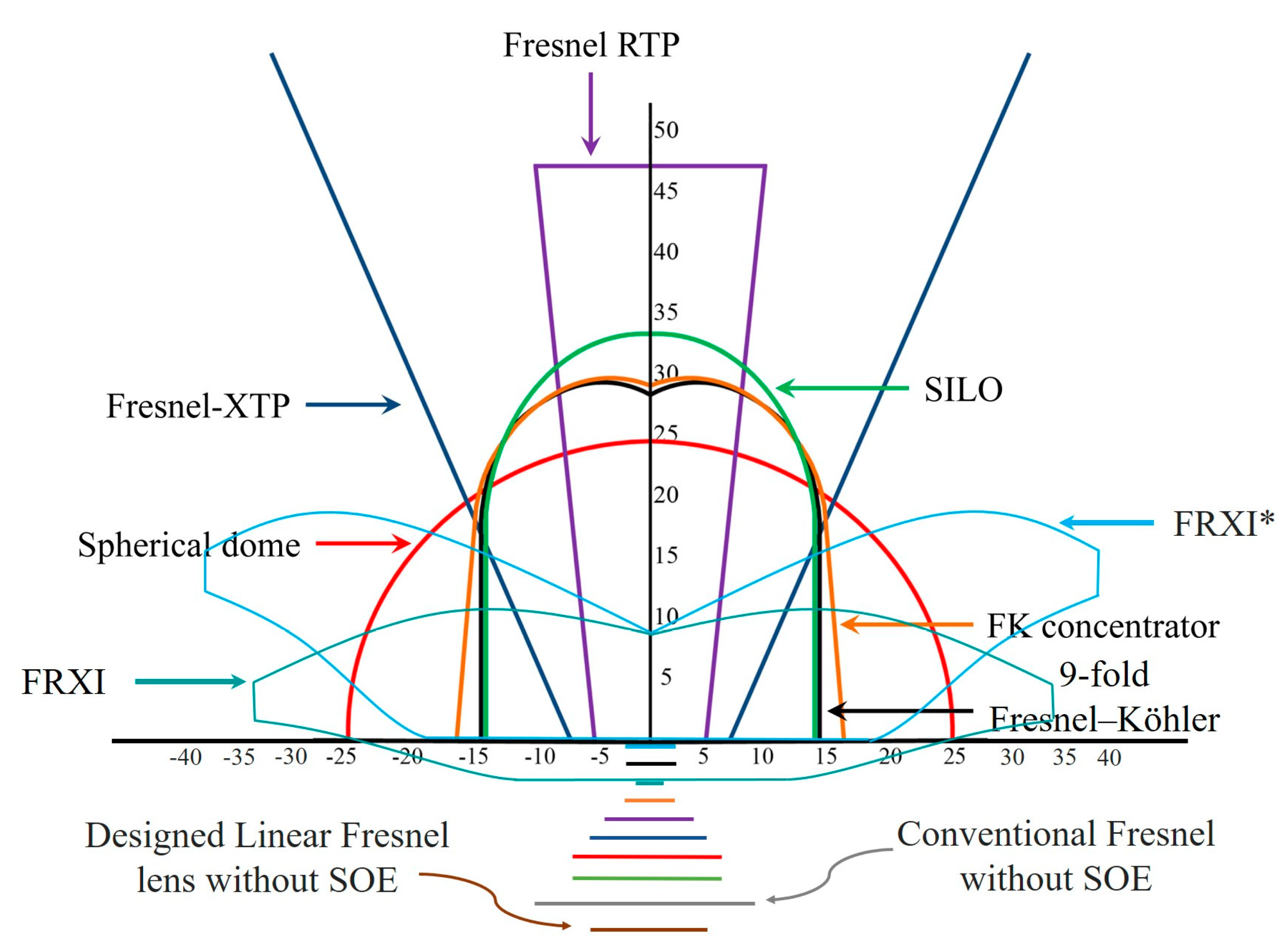
As a result, the efficiency of solar cells increases to the maximum value and then decreases although concentration ratio is still increasing. In the current CPV technology, the optimum concentration ratio can be different and will usually be from 400 to 600 times depending on the quality of the solar cells and the photovoltaic system. Therefore, the results show the concentration ratio by 406 times with the acceptance angle by 1° that can be a good potential candidate to consider being an optical concentrator system of CPV system. To more clearly, the results of the designed linear Fresnel lens are used to compare to other study results from other research groups. In comparison, all concentrator systems have the same entry aperture area 625 cm2 and the same acceptance angle (αa = 1°). The following table shows the comparison of concentration ratio Cg and fnumber with the same acceptance angle while Figure 17 shows the size comparison of multi-junction solar cells and secondary optical element with the same acceptance angle.
Based on comparison in Table 2 and Figure 17, if we need a super high concentration for the CPV system, F-RXI type of optical concentrator system is the best choice because of highest concentration ratio. In contrast, if we take care about the compact property of CPV system, RTP type of optical concentrator system is the best choice because of smallest fnumber. However, depending on the structure of CPV, designer can choose a suitable type of optical concentrator system. As above-mentioned, if designer choose a medium concentration ratio and fnumber to avoid facing with serious issues of high temperature and the loss due to the electrode resistance and the series resistance, our design can be a good potential choice.
There are some studies about designing CPV system without SOE that is published in literatures before. Gonzalez et al. [39] used the Simultaneous Multiple Surface (SMS) method to increase the acceptance angle a uniformity of irradiance distribution of the linear Fresnel lens without SOE. The results in this study show that the uniformity and acceptance are improved much, however, the structure of the designed Fresnel lens is just suitable for low concentrator photovoltaic (LCPV) because of low concentration ratio (less than 100 times). Another study comes from Ryu et al. [42]. In this design, the author tried to design an optical concentrator system with high uniformity irradiance distribution without SOE. The flat Fresnel lens was built by some parts; each of them collects and distributes the sunlight to different places on the receiver. This structure obtains high uniformity with acceptance angle greater 1° for all of concentration ratio from 9 to 121 times. Although the results show that the uniformity is good with mild acceptance angle, the concentration ratio is small so that this structure is not suitable for HCPV system. A prototype of flat Fresnel lens designed by Pan et al. [43] was introduced by using the idea to change all pitches of the Fresnel concentrator focusing on the different position of the receiver. The designed Fresnel lens obtained high concentration ratio around 1018 times, but the acceptance is small 0.305°. Therefore, it is difficult to apply the designed Fresnel lens to CPV system without in real conditions. Comparing to all these types of optical concentrator system without the SOE abovementioned, our novel designed linear Fresnel lens has good properties, which help our designed lens can become a potential choice for HCPV system.
Generally, a CPV system consist of three main components: optical concentrator, high effective solar cells, and sun tracking system. Assume that all CPV systems use the same the best commercial version of multi-junction solar cell and sun tracking system in the market so we can compare between CPV systems to each other based on their optical concentrator systems. Therefore, the module cost will differ depending on the size of multi-junction solar cell and the cost of production of Fresnel lens and SOE. However, the estimation of the cost of CPV system is complex because the cost of the working CPV system depends on the reliability and the effective of that system in real conditions. To simplify the comparison, a comparison among all types of optical concentrators in Table 2 is just focused on the size of multi-junction solar cell and the cost of production. In term of multi-junction solar cell, the concentration ratio is higher, the size of solar cell is smaller so that the module cost is cheaper. In this area, F-RXI is the best choice. However, a concentration ratio from 300–600 is a good choice in real conditions because of considering electrical loss by series loss and the temperature issue. Therefore, our designed linear Fresnel lens is a good candidate. In addition, the optical concentrator system based on our designed linear Fresnel lens does not need to use SOE so that the cost of module is decreased significantly comparing to other types of optical concentrators. In term of production cost of the lens, there are some technologies to manufacture Fresnel lens or Primary optical component (POE) for CPV system, such as the embossing method (Zhang et al. [53]), molding method (Huang et al. [54]), and extrusion method (Benz et al. [55]). The conventional linear Fresnel lens can be manufactured easily by these methods. However, our designed linear Fresnel lens has a special structure, in which two groove surfaces is placed perpendicular to each other so that the extrusion method cannot be used to manufacture. Fortunately, the embossing method is a mature method to manufacture conventional Fresnel lens can be applied to make our designed linear Fresnel without any addition special skill so that the production cost of the novel linear Fresnel lens is similar that of conventional linear Fresnel lens. In conclusion, the cost of bigger multi-junction solar cells in our designed concentrator system comparing to FK, 9-Fold, F-RXI, F-RXI* types of optical concentrators can be compensated by removing SOE. Moreover, although our designed linear Fresnel lens has a special structure, which the extrusion method could not apply to manufacture, we can use the mature embossing method to manufacture easily so that the production cost of POE is similar that of other types of optical concentrators. To more clearly, a prototype of the designed linear Fresnel lens is needed to manufacture to apply to CPV system. After that, a comparison about performance and cost production can be implemented with more accuracy between our designed optical concentrator and other types of other optical concentrators.
6. Conclusions
In this study, the design of the novel linear Fresnel lens is presented in detail. The lens has two groove surfaces (upper and lower groove surfaces) placed perpendicular to each other. Each surface focuses direct sunlight on one dimension so that the whole lens can collect and distribute the sunlight on two dimensions, thereby, increasing the concentration ratio. Furthermore, a new technique using multi-focal points to distribute the sunlight uniformly over the receiver is proposed, in which each groove has its own focal point on which all rays arriving at the groove converge. The position of the focal point for each groove is determined by using the edge ray theorem, Snell’s law, and the conservation of the optical path length so that the bundle of rays can be distributed uniformly from the center to the extreme point of the receiver. The simulation results show that the irradiance distribution is a square area that helps the concentrated sunlight to match better to the shape of the solar cells. In addition, the irradiance distribution is quite uniform with the uniformity reaches around 77% for both horizontal and vertical investigation lines. An acceptance angle with an acceptable value of about 0.84° is also investigated in this research to choose or design a suitable sun tracking system for the CPV. All these factors substantially help to enhance the performance and decrease the cost of the CPV system for massive installation in real conditions. Therefore, a concentrator based on the novel structure of the linear Fresnel lens can help to promote the development of high performance and effective cost of the CPV system generation.
In future research, the prototype of the designed lens will be produced and then experiments using that prototype as a concentrator in the CPV system can be carried out to check the performance of the designed lens. The results of the experiment will be compared to the simulation results to understand and optimize the novel lens and the CPV system.
Author Contributions
All authors contributed extensively to the work presented in this paper. T.T.P. proposed the research idea to design a concentrator for a CPV system. S.S. supervised the design and simulation process of the system. T.T.P., N.H.V., and S.S. together discussed setting up the conditions for the simulation in the LightTools software. T.T.P. carried out the design and the simulation, collected the dataset, and wrote the manuscript. S.S. and N.H.V. contributed to the manuscript revision.
Funding
This research was funded by the Basic Science Research Program through the National Research Foundation of Korea (NRF) funded by the Ministry of Education (2017R1D1A1B03031338).
Conflicts of Interest
The authors declare no conflict of interest.
References
- Fraunhofer, I. New world record for solar cell efficiency at 46% French-German cooperation confirms competitive advantage of European photovoltaic industry. Press Release 2014, 26. Available online: http://www.ise.fraunhofer.de/en/press-and-media/press-releases/press-releases-2014/new-world-record-for-solar-cell-efficiency-at-46-percent (accessed on 26 March 2019).
- Abbott, D. Keeping the energy debate clean: How do we supply the world’s energy needs? Proc. IEEE 2010, 98, 42–66. [Google Scholar] [CrossRef]
- Khamooshi, M.; Salati, H.; Egelioglu, F.; Hooshyar Faghiri, A.; Tarabishi, J.; Babadi, S. A review of solar photovoltaic concentrators. Int. J. Photoenergy 2014, 2014. [Google Scholar] [CrossRef]
- Mendoza, B. Total solar irradiance and climate. Adv. Space Res. 2005, 35, 882–890. [Google Scholar] [CrossRef]
- Chukwuka, C.; Folly, K.A. Overview of concentrated photovoltaic (CPV) cells. J. Power Energy Eng. 2014, 2, 1. [Google Scholar] [CrossRef]
- Morales-Acevedo, A. Solar Cells: Research and Application Perspectives; InTech: Rijeka, Croatia, 2013. [Google Scholar] [CrossRef]
- Tanabe, K. A review of ultrahigh efficiency III-V semiconductor compound solar cells: Multijunction tandem, lower dimensional, photonic up/down conversion and plasmonic nanometallic structures. Energies 2009, 2, 504–530. [Google Scholar] [CrossRef]
- Buljan, M.; Mendes-Lopes, J.; Benítez, P.; Miñano, J.C. Recent trends in concentrated photovoltaics concentrators’ architecture. J. Photonics Energy 2014, 4, 040995. [Google Scholar] [CrossRef] [Green Version]
- Luque, A.; Hegedus, S. Handbook of Photovoltaic Science and Engineering; John Wiley & Sons: Hoboken, NJ, USA, 2011. [Google Scholar] [CrossRef]
- Pérez-Higueras, P.; Fernández, E.F. High Concentrator Photovoltaics: Fundamentals, Engineering and Power Plants; Springer: Berlin, Germany, 2015. [Google Scholar] [CrossRef]
- Shanks, K.; Senthilarasu, S.; Mallick, T.K. Optics for concentrating photovoltaics: Trends, limits and opportunities for materials and design. Renew. Sustain. Energy Rev. 2016, 60, 394–407. [Google Scholar] [CrossRef] [Green Version]
- Parida, B.; Iniyan, S.; Goic, R. A review of solar photovoltaic technologies. Renew. Sustain. Energy Rev. 2011, 15, 1625–1636. [Google Scholar] [CrossRef]
- Chong, K.-K.; Lau, S.-L.; Yew, T.-K.; Tan, P.C.-L. Design and development in optics of concentrator photovoltaic system. Renew. Sustain. Energy Rev. 2013, 19, 598–612. [Google Scholar] [CrossRef]
- Dreger, M.; Wiesenfarth, M.; Kisser, A.; Schmid, T.; Bett, A.W. Development and investigation of a CPV module with Cassegrain mirror optics. AIP Conf. Proc. 2014, 177, 177–182. [Google Scholar]
- Rumyantsev, V.D. Solar concentrator modules with silicone-on-glass Fresnel lens panels and multijunction cells. Opt. Express 2010, 18, A17–A24. [Google Scholar] [CrossRef] [PubMed]
- Cucco, S.; Faranda, R.; Invernizzi, F.; Leva, S. Analysis of a Fresnel lenses concentrator. In Proceedings of the Power and Energy Society General Meeting, Manchester Grand Hyatt, San Diego, CA, USA, 22–26 July 2012; pp. 1–8. [Google Scholar]
- Erismann, F. Design of a plastic aspheric Fresnel lens with a spherical shape. Opt. Eng. 1997, 36, 988–992. [Google Scholar] [CrossRef]
- Tien, N.X.; Shin, S. A Novel Concentrator Photovoltaic (CPV) System with the Improvement of Irradiance Uniformity and the Capturing of Diffuse Solar Radiation. Appl. Sci. 2016, 6, 251. [Google Scholar] [CrossRef]
- Xie, W.; Dai, Y.; Wang, R.; Sumathy, K. Concentrated solar energy applications using Fresnel lenses: A review. Renew. Sustain. Energy Rev. 2011, 15, 2588–2606. [Google Scholar] [CrossRef]
- Bahaidarah, H.M.; Tanweer, B.; Gandhidasan, P.; Rehman, S. A combined optical, thermal and electrical performance study of a V-trough PV system—Experimental and analytical investigations. Energies 2015, 8, 2803–2827. [Google Scholar] [CrossRef]
- Du, B.; Hu, E.; Kolhe, M. Performance analysis of water cooled concentrated photovoltaic (CPV) system. Renew. Sustain. Energy Rev. 2012, 16, 6732–6736. [Google Scholar] [CrossRef]
- Rosell, J.; Vallverdu, X.; Lechon, M.; Ibanez, M. Design and simulation of a low concentrating photovoltaic/thermal system. Energy Convers. Manag. 2005, 46, 3034–3046. [Google Scholar] [CrossRef]
- Espinet, P.; Algora, C.; Rey-Stolle, I.; Garcia, I.; Baudrit, M. Electroluminescence characterization of III–V multi-junction solar cells. In Proceedings of the Photovoltaic Specialists Conference, 2008. PVSC’08, San Diego, CA, USA, 11–16 May 2008; pp. 1–6. [Google Scholar]
- Languy, F.; Fleury, K.; Lenaerts, C.; Loicq, J.; Regaert, D.; Thibert, T.; Habraken, S. Flat Fresnel doublets made of PMMA and PC: Combining low cost production and very high concentration ratio for CPV. Opt. Express 2011, 19, A280–A294. [Google Scholar] [CrossRef]
- Leutz, R.; Suzuki, A. Nonimaging Fresnel Lenses: Design and Performance of Solar Concentrators; Springer: Berlin, Germany, 2012; Volume 83. [Google Scholar]
- Jing, L.; Liu, H.; Zhao, H.; Lu, Z.; Wu, H.; Wang, H.; Xu, J. Design of novel compound Fresnel lens for high-performance photovoltaic concentrator. Int. J. Photoenergy 2012, 2012. [Google Scholar] [CrossRef]
- Sharaf, O.Z.; Orhan, M.F. Concentrated photovoltaic thermal (CPVT) solar collector systems: Part I–Fundamentals, design considerations and current technologies. Renew. Sustain. Energy Rev. 2015, 50, 1500–1565. [Google Scholar] [CrossRef]
- Ullah, I.; Shin, S.-Y. Development of optical fiber-based daylighting system with uniform illumination. J. Opt. Soc. Korea 2012, 16, 247–255. [Google Scholar] [CrossRef]
- Chen, Y.-C.; Chiang, H.-W. Design of the secondary optical elements for concentrated photovoltaic units with Fresnel lenses. Appl. Sci. 2015, 5, 770–786. [Google Scholar] [CrossRef]
- Victoria, M.; Domínguez, C.; Antón, I.; Sala, G. Comparative analysis of different secondary optical elements for aspheric primary lenses. Optics Express 2009, 17, 6487–6492. [Google Scholar] [CrossRef] [PubMed]
- Horowitz, K.A.; Woodhouse, M.; Lee, H.; Smestad, G.P.A.; Woodhouse, M.; Lee, H.; Smestad, G.P. A bottom-up cost analysis of a high concentration PV module. In AIP Conference Proceedings; AIP Publishing: Melville, NY, USA, 2015; Volume 1679, p. 100001. [Google Scholar]
- Luther, J.; Bett, A.; Burger, B.; Dimroth, F. High concentration photovoltaics based on III–V multi-junction solar cells. In Proceedings of the 21st European Photovoltaic Solar Energy Conference, Dresden, Germany, 4–8 September 2006; pp. 2054–2057. [Google Scholar]
- Messmer, E.R. CPV market evolution and the potential in cost reduction of CPV modules. In Proceedings of the 9th Conference on Concentrator Photovoltaic Systems (CPV-9), Miyazaki, Japan, 15–17 April 2013. [Google Scholar]
- Philipps, S.P.; Bett, A.W.; Horowitz, K.; Kurtz, S. Current Status of Concentrator Photovoltaic (CPV) Technology; NREL (National Renewable Energy Laboratory): Golden, CO, USA, 2015.
- Tomosk, S.; Wright, D.; Hinzer, K.; Haysom, J.E. Analysis of present and future financial viability of high-concentrating photovoltaic projects. In High Concentrator PhotoVoltaics; Springer: Berlin, Germany, 2015; pp. 377–400. [Google Scholar] [CrossRef]
- Algora, C.; Rey-Stolle, I. Handbook on Concentrator Photovoltaic Technology; John Wiley & Sons: Hoboken, NJ, USA, 2016. [Google Scholar] [CrossRef]
- Zhuang, Z.; Yu, F. Optimization design of hybrid Fresnel-based concentrator for generating uniformity irradiance with the broad solar spectrum. Opt. Laser Technol. 2014, 60, 27–33. [Google Scholar] [CrossRef]
- Leutz, R.; Suzuki, A.; Akisawa, A.; Kashiwagi, T. Design of a nonimaging fresnel lens for solar concentrators. Solar Energy 1999, 65, 379–387. [Google Scholar] [CrossRef]
- González, J.C. Design and analysis of a curved cylindrical Fresnel lens that produces high irradiance uniformity on the solar cell. Appl. Opt. 2009, 48, 2127–2132. [Google Scholar] [CrossRef]
- Yamada, N.; Okamoto, K. Experimental measurements of a prototype high concentration Fresnel lens CPV module for the harvesting of diffuse solar radiation. Opt. Express 2014, 22, A28–A34. [Google Scholar] [CrossRef]
- Akisawa, A.; Hiramatsu, M.; Ozaki, K. Design of dome-shaped non-imaging Fresnel lenses taking chromatic aberration into account. Solar Energy 2012, 86, 877–885. [Google Scholar] [CrossRef]
- Ryu, K.; Rhee, J.-G.; Park, K.-M.; Kim, J. Concept and design of modular Fresnel lenses for concentration solar PV system. Solar Energy 2006, 80, 1580–1587. [Google Scholar] [CrossRef]
- Pan, J.-W.; Huang, J.-Y.; Wang, C.-M.; Hong, H.-F.; Liang, Y.-P. High concentration and homogenized Fresnel lens without secondary optics element. Opt. Commun. 2011, 284, 4283–4288. [Google Scholar] [CrossRef]
- Pham, T.T.; Vu, N.H.; Shin, S. Daylighting System Based on Novel Design of Linear Fresnel lens. Buildings 2017, 7, 92. [Google Scholar] [CrossRef]
- Vu, N.H.; Pham, T.T.; Shin, S. LED Uniform Illumination Using Double Linear Fresnel Lenses for Energy Saving. Energies 2017, 10, 2091. [Google Scholar] [CrossRef]
- Chaves, J. Introduction to Nonimaging Optics; CRC Press: Boca Raton, FL, USA, 2008. [Google Scholar]
- Messmer, E.R. Solar Cell Efficiency vs. Module Power Output: Simulation of a Solar Cell in a CPV Module. In Solar Cells-Research and Application Perspectives; InTech: Rijeka, Croatia, 2013. [Google Scholar] [CrossRef]
- Xu, Q.; Ji, Y.; Riggs, B.; Ollanik, A.; Farrar-Foley, N.; Ermer, J.H.; Romanin, V.; Lynn, P.; Codd, D.; Escarra, M.D. A transmissive, spectrum-splitting concentrating photovoltaic module for hybrid photovoltaic-solar thermal energy conversion. Solar Energy 2016, 137, 585–593. [Google Scholar] [CrossRef]
- Yavrian, A.; Tremblay, S.; Levesque, M.; Gilbert, R. How to increase the efficiency of a high concentrating PV (HCPV) by increasing the acceptance angle to ±3.2°. In AIP Conference Proceedings; AIP: College Park, MD, USA, 2013; pp. 197–200. [Google Scholar]
- Racharla, S.; Rajan, K. Solar tracking system—A review. Int. J. Sustain. Eng. 2017, 10, 72–81. [Google Scholar] [CrossRef]
- Miñano, J.C.; Benítez, P.; Zamora, P.; Buljan, M.; Mohedano, R.; Santamaría, A.J.O.E. Free-form optics for Fresnel-lens-based photovoltaic concentrators. Opt. Express 2013, 21, A494–A502. [Google Scholar] [CrossRef]
- Mendes-Lopes, J.; Benítez, P.; Zamora, P.; Miñano, J.C.J.O.E. 9-fold Fresnel–Köhler concentrator with Fresnel lens of variable focal point. Opt. Express 2014, 22, A1153–A1163. [Google Scholar] [CrossRef] [PubMed]
- Zhang, X.; Liu, K.; Shan, X.; Liu, Y.J.O.E. Roll-to-roll embossing of optical linear Fresnel lens polymer film for solar concentration. Opt. Express 2014, 22, A1835–A1842. [Google Scholar] [CrossRef]
- Huang, C.-Y.; Chen, C.-C.; Chou, H.-Y.; Chou, C.-P. Fabrication of fresnel lens by glass molding technique. Opt. Rev. 2013, 20, 202–204. [Google Scholar] [CrossRef]
- Benz, V.; Berkenkopf, M.; Fischer, U.; Lorenz, H.; Meier-Kaiser, M. Process for Manufacture of Fresnel Lenses. U.S. Patent 5,870,233, 9 February 1999. [Google Scholar]
Figure 1.
Two types of Fresnel lenses constructed from a cross-section of the grooves with (a) extruding axis and (b) revolving axis.
Figure 1.
Two types of Fresnel lenses constructed from a cross-section of the grooves with (a) extruding axis and (b) revolving axis.
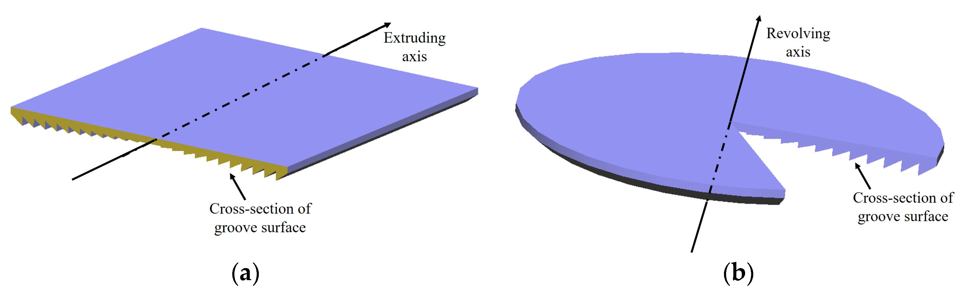
Figure 2.
The structure of the novel Fresnel lens consisting of two surfaces placed perpendicular to each other.
Figure 2.
The structure of the novel Fresnel lens consisting of two surfaces placed perpendicular to each other.
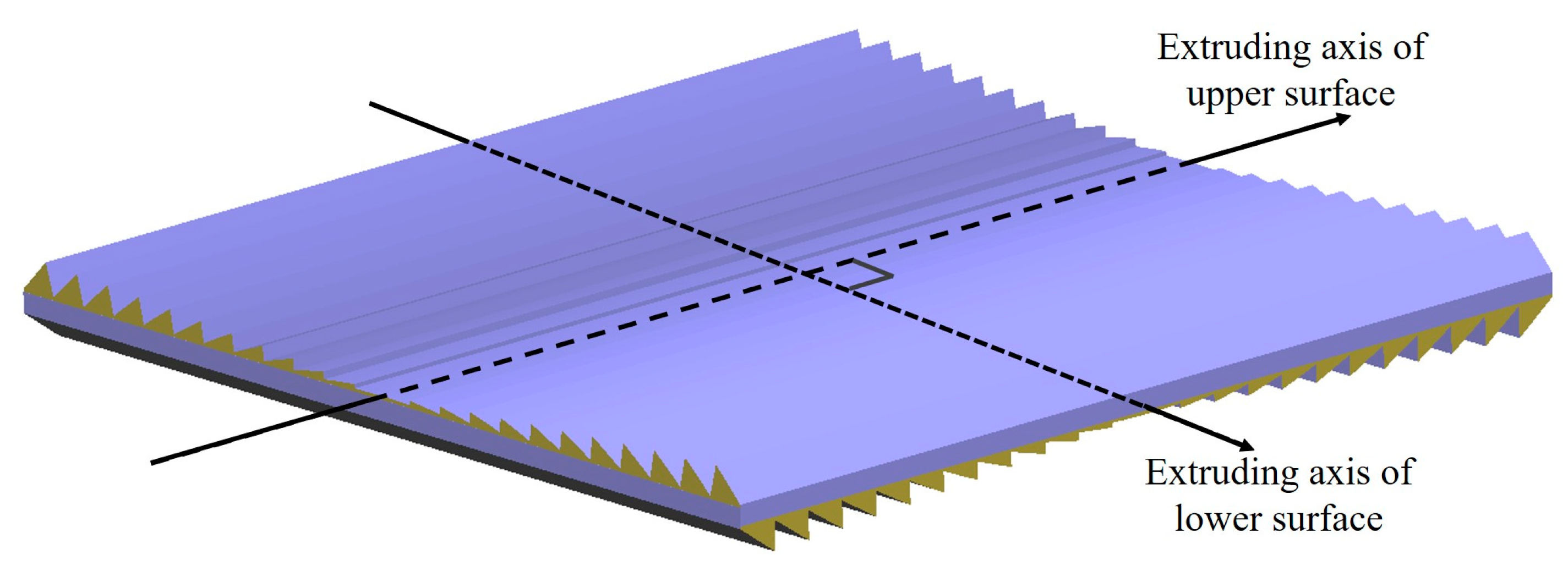
Figure 3.
The flowchart of the lens designed in the MATLAB program.
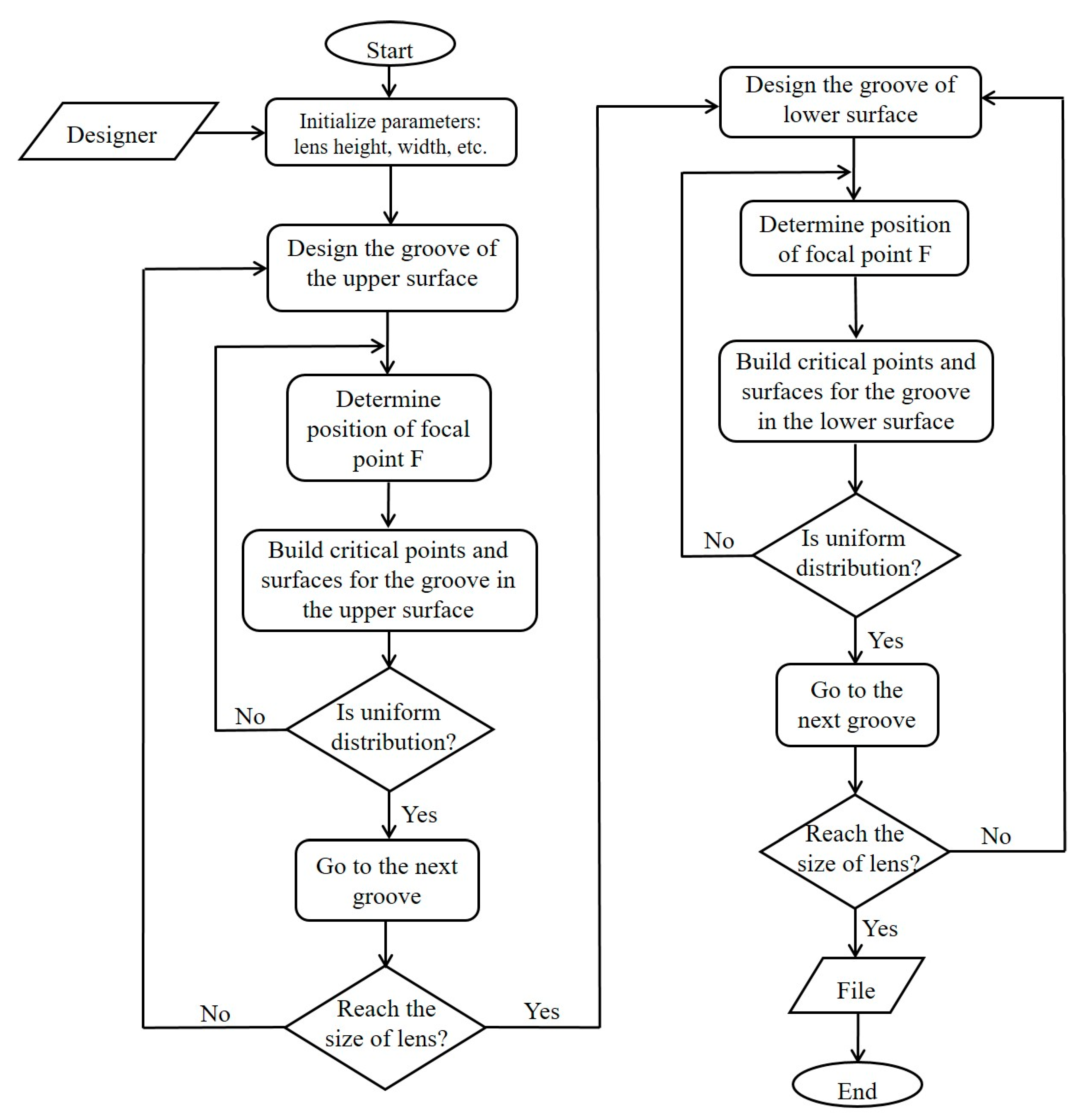
Figure 4.
Angular aperture of sunlight θS and acceptance angle α.
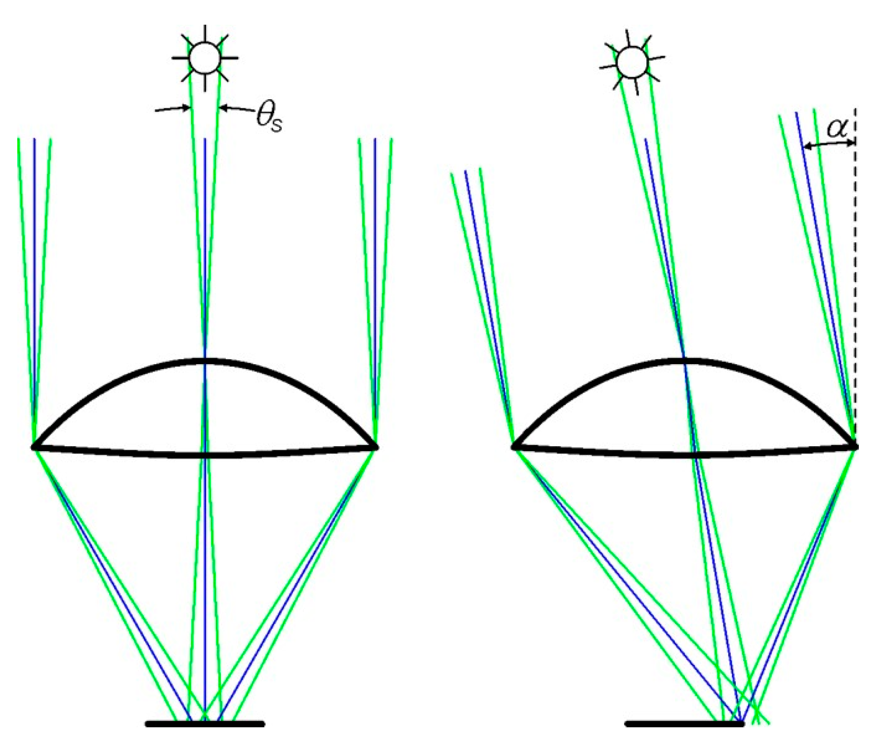
Figure 5.
The basic of the edge ray principle, in which the illumination energy from light source S is transferred to receiver R without needed image formation.
Figure 5.
The basic of the edge ray principle, in which the illumination energy from light source S is transferred to receiver R without needed image formation.
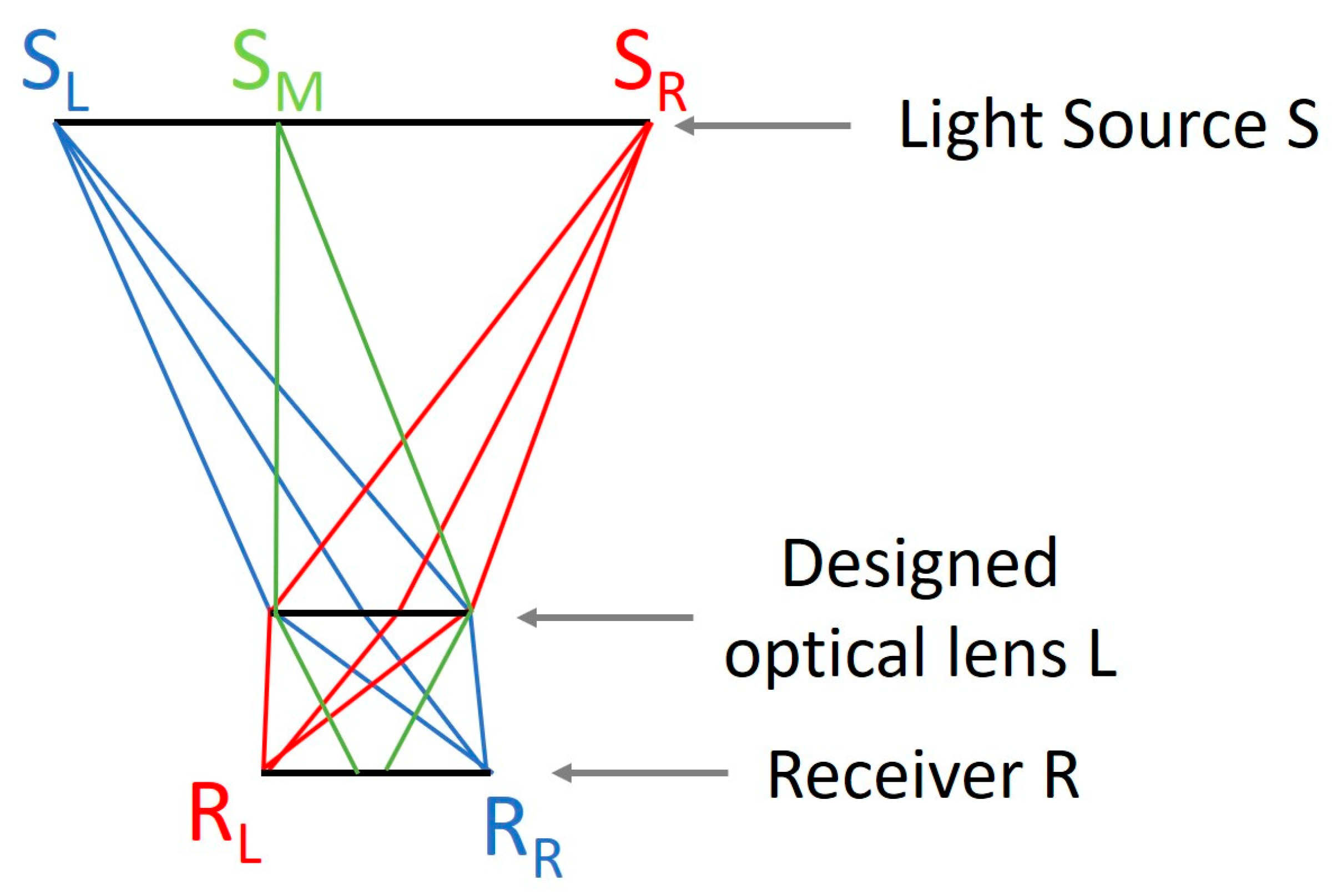
Figure 6.
The edge ray principle is applied to design one groove, in which the left edge ray, the right edge ray, and an example of ray between left and right edge rays coming to one groove are shown.
Figure 6.
The edge ray principle is applied to design one groove, in which the left edge ray, the right edge ray, and an example of ray between left and right edge rays coming to one groove are shown.

Figure 7.
The irradiance distribution in the conventional design of the Fresnel lens, in which there is only one focal point at the center of the receiver.
Figure 7.
The irradiance distribution in the conventional design of the Fresnel lens, in which there is only one focal point at the center of the receiver.
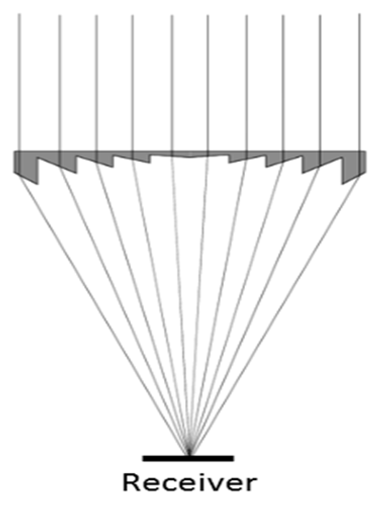
Figure 8.
The new technique to distribute the sunlight uniformly over the receiver using multi-focal points that can be either (a) under the receiver or (b) above the lens depending on the size of the receiver and the grooves. Note: The figures are not drawn to scale.
Figure 8.
The new technique to distribute the sunlight uniformly over the receiver using multi-focal points that can be either (a) under the receiver or (b) above the lens depending on the size of the receiver and the grooves. Note: The figures are not drawn to scale.

Figure 9.
The way to distribute the direct sunlight in each groove of the linear Fresnel lens as an upper groove surface.
Figure 9.
The way to distribute the direct sunlight in each groove of the linear Fresnel lens as an upper groove surface.

Figure 10.
The distribution of direct sunlight in each groove of the linear Fresnel lens as a lower groove surface.
Figure 10.
The distribution of direct sunlight in each groove of the linear Fresnel lens as a lower groove surface.
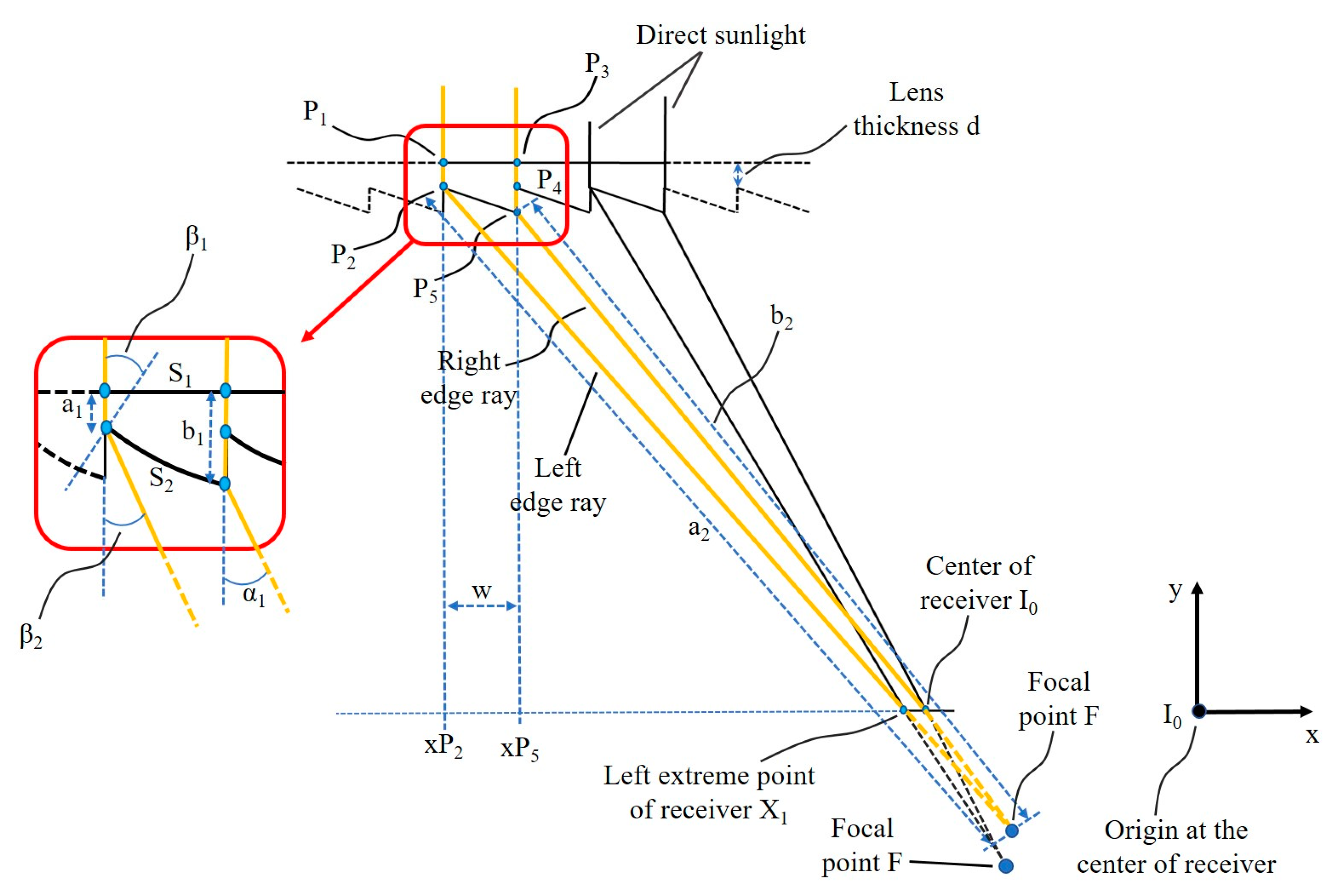
Figure 11.
The ray tracing of sunlight convergence on one dimension onto the focal line using the linear Fresnel lens with (a) the lower groove surface and (b) the upper groove surface.
Figure 11.
The ray tracing of sunlight convergence on one dimension onto the focal line using the linear Fresnel lens with (a) the lower groove surface and (b) the upper groove surface.

Figure 12.
The ray tracing of sunlight convergence on two dimensions using the novel Fresnel lens with two groove surfaces (upper and lower surfaces) placed perpendicular to each other.
Figure 12.
The ray tracing of sunlight convergence on two dimensions using the novel Fresnel lens with two groove surfaces (upper and lower surfaces) placed perpendicular to each other.
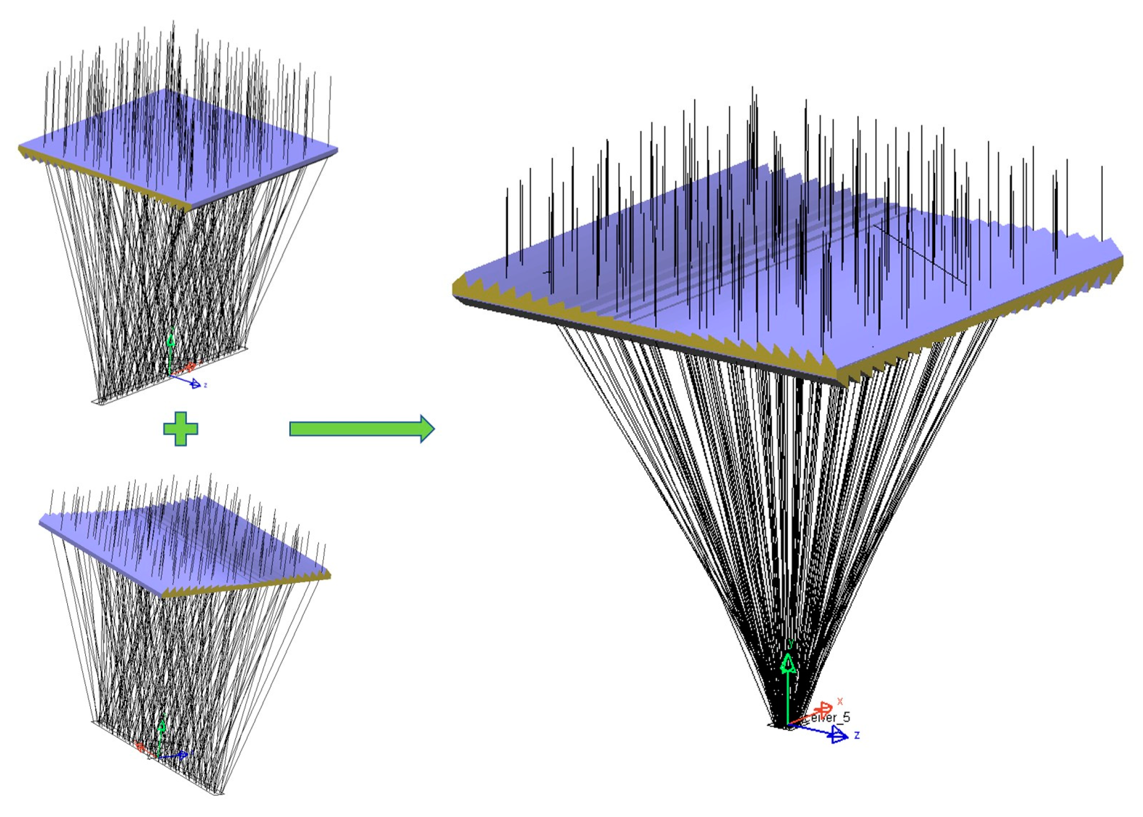
Figure 13.
Four structures of the POE using a combination of two individual Fresnel lenses that are constructed from (a) two lower groove surfaces, (b) two upper groove surfaces, (c) one lower groove surface above one upper groove surface, and (d) one upper groove surface above one lower groove surface.
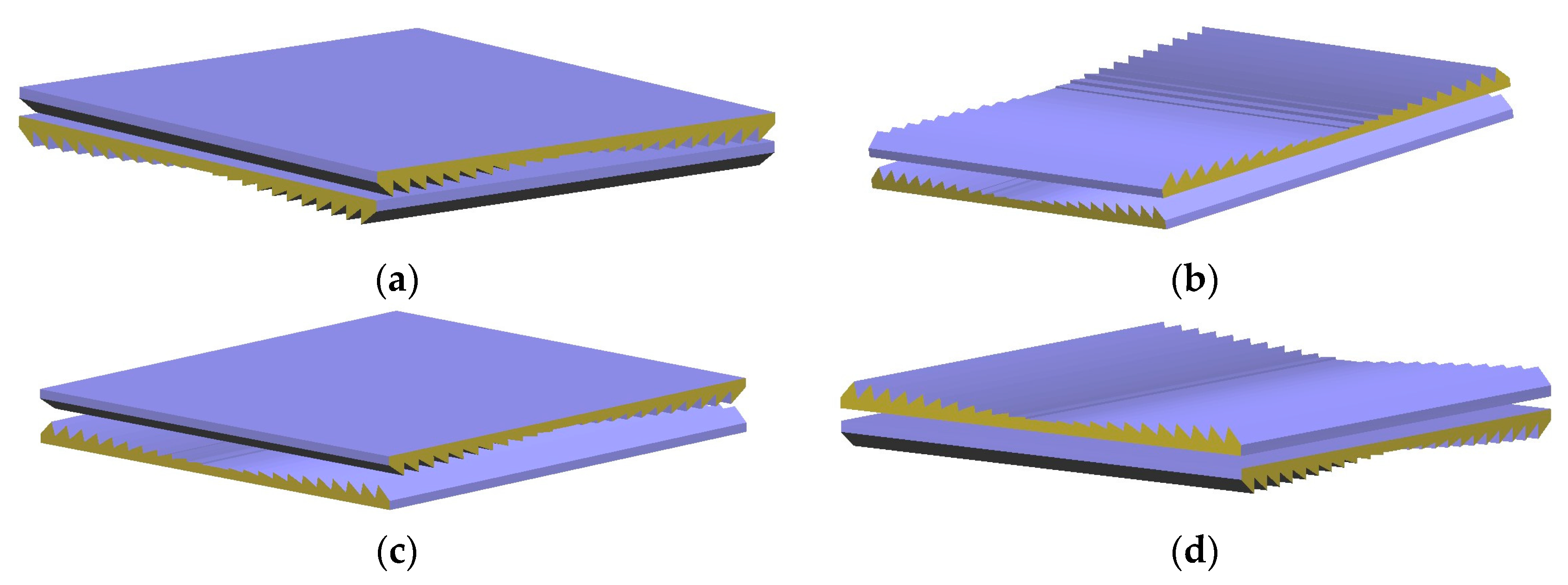
Figure 14.
Ray tracing of the novel designed lens, irradiance distribution of the sunlight over the receiver, and the uniformity on the horizontal and vertical investigation lines.
Figure 14.
Ray tracing of the novel designed lens, irradiance distribution of the sunlight over the receiver, and the uniformity on the horizontal and vertical investigation lines.
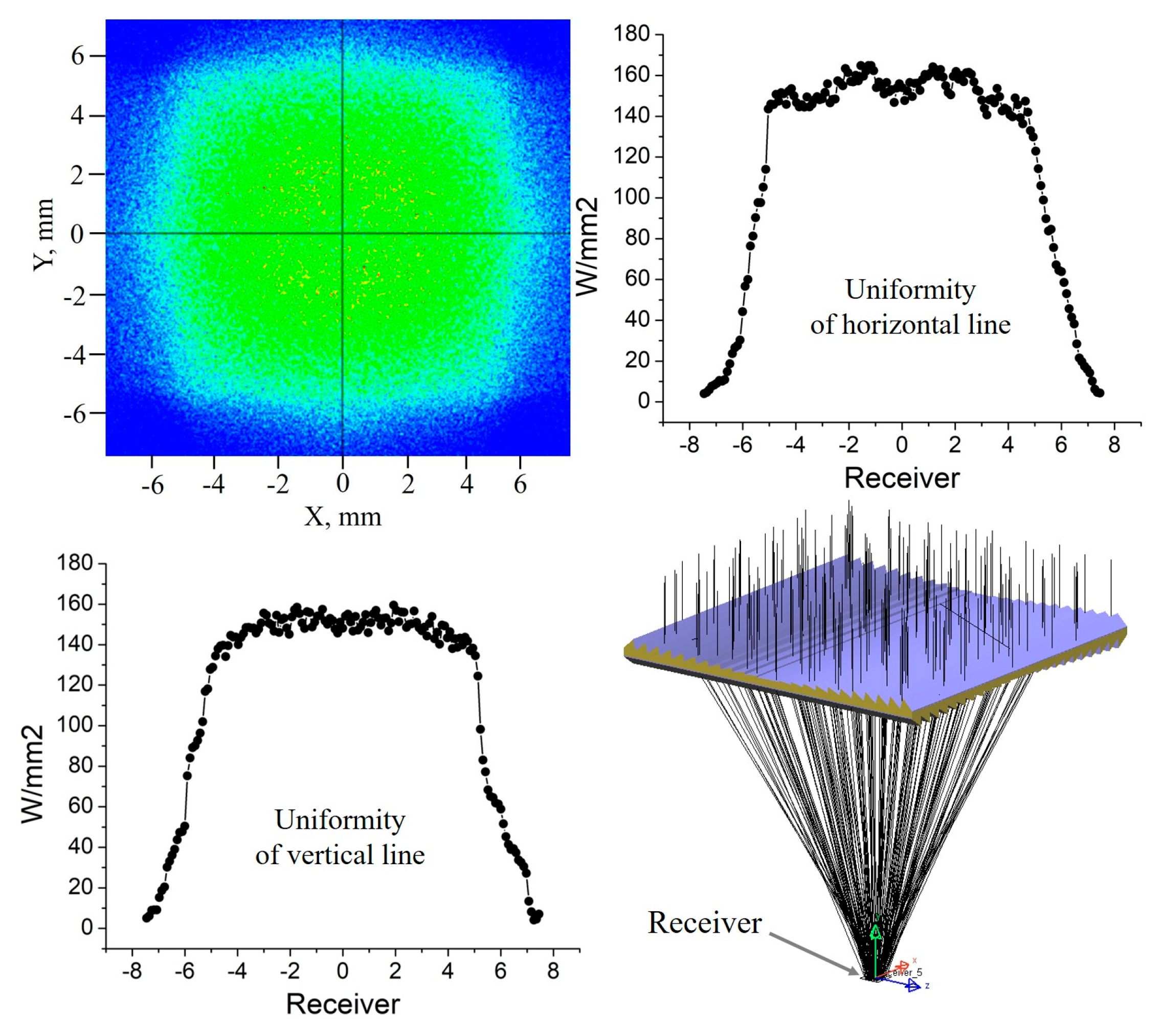
Figure 15.
Ray tracing of the upper surface and the loss areas on the upper surface.
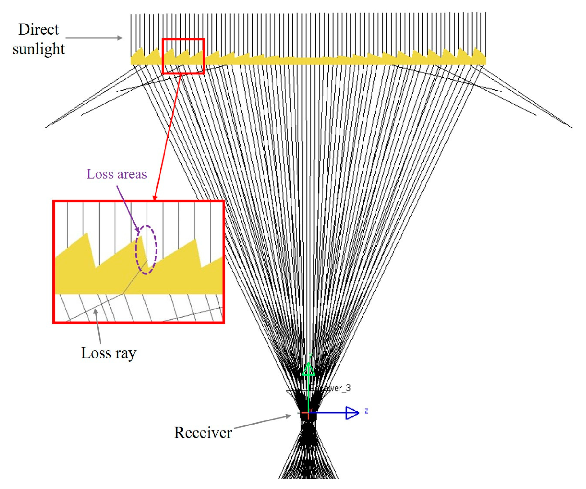
Figure 16.
The relative optical efficiency depends on the incident angle of the direct sunlight.

Figure 17.
Cross section views of some types of SOEs and size comparison of these optical concentrator systems with the same acceptance angle. The structures and designs of these optical concentrator systems are described in detail in Miñano et al. [51] and Mendes-Lopes et al. [52].

Table 1.
The parameters of the designed linear Fresnel lens for ray tracing and simulation.
| Design Parameters | Values |
|---|---|
| Dimension of lens | 240 × 240 mm |
| Height of lens | 240 mm |
| F-number | 1 |
| Dimension of receiver | 10 × 10 mm |
| Number of grooves | 24 |
| Material | Polymethyl methacrylate (PMMA) |
| Thickness | 5 mm |
| Concentration ratio | 576 times |
| Wavelength for ray tracing | 550 nm |
| Spectrum for light source | 390–1000 nm |
| Power of light source | 20 kW |
| Number of rays for ray tracing | 2,000,000 rays |
| Refractive index | 1.492 at 550 nm |
Table 2.
Comparison of concentration ratio and fnumber with the same acceptance angle between our proposed design and other designs that described in Minano et al. [51].
Table 2.
Comparison of concentration ratio and fnumber with the same acceptance angle between our proposed design and other designs that described in Minano et al. [51].
| Concentrator Type | fnumber | Concentration Ratio Cg | Acceptance Angle αa |
|---|---|---|---|
| No SOE | 1.5 | 104 | 1° |
| Spherical dome | 1.5 | 257 | 1° |
| SILO | 1.2 | 248 | 1° |
| Our proposed design | 1.0 | 406 | 1° |
| XTP | 1.3 | 425 | 1° |
| RTP | 0.85 | 677 | 1° |
| FK | 1.0 | 1057 | 1° |
| 9-Fold | 1.0 | 1062 | 1° |
| F-RXI | 1.4 | 2300 | 1° |
| F-RXI* | 1.4 | 1750 | 1° |
© 2019 by the authors. Licensee MDPI, Basel, Switzerland. This article is an open access article distributed under the terms and conditions of the Creative Commons Attribution (CC BY) license (http://creativecommons.org/licenses/by/4.0/).
Share and Cite
MDPI and ACS Style
Pham, T.T.; Vu, N.H.; Shin, S. Novel Design of Primary Optical Elements Based on a Linear Fresnel Lens for Concentrator Photovoltaic Technology. Energies 2019, 12, 1209. https://doi.org/10.3390/en12071209
AMA Style
Pham TT, Vu NH, Shin S. Novel Design of Primary Optical Elements Based on a Linear Fresnel Lens for Concentrator Photovoltaic Technology. Energies. 2019; 12(7):1209. https://doi.org/10.3390/en12071209
Chicago/Turabian StylePham, Thanh Tuan, Ngoc Hai Vu, and Seoyong Shin. 2019. "Novel Design of Primary Optical Elements Based on a Linear Fresnel Lens for Concentrator Photovoltaic Technology" Energies 12, no. 7: 1209. https://doi.org/10.3390/en12071209
Note that from the first issue of 2016, this journal uses article numbers instead of page numbers. See further details here.