1. Introduction
Faced with an energy crisis and serious environmental problems, countries are developing renewable energy technologies in order to meet their domestic energy demand and strive for sustainable development. However, the random and intermittent characteristics of renewable energy sources (RESs) impact the power system reliability [
1,
2].
The introduction of energy storage devices effectively solves the problem of grid-connected renewable energy generation [
3,
4]. However, the high investment and construction costs of energy storage devices will increase the cost of the energy storage system (ESS). The application of electric vehicles (EVs) as mobile energy storage units (MESUs) has drawn widespread attention under this circumstance [
5,
6]. A large amount of EVs are connected to the power grid, which is equivalent to controllable loads or the mobile energy storage cluster (MESC) that supports ancillary services. By controlling the charging/discharging of EVs’ batteries, it could not only promote the consumption of RESs, but also be beneficial to peak-load shifting and valley-filling [
7,
8]. Moreover, large amounts of EVs can contribute to voltage regulation and frequency regulation when considering the characteristics of energy storage [
9]. According to the concept of vehicle-to-grid (V2G), the energy stored in the batteries of EVs can also be sent back to the power grid when there is a shortage of active power [
10]. Since an EV is a carrier of batteries, the control strategy designed to allocate energy among EVs is equivalent to the control method of an energy storage unit (ESU). Due to the unique advantages of EVs in terms of their demand response (DR) and energy storage, the rational dispatch of energy in the mobile energy storage system (MESS) will be an inevitable requirement for the development of smart grids [
11].
In terms of regulation control of ESUs, a past study [
12] established a joint scheduling model of a wind power storage hybrid system on multiple time scales and gave the production plan of the hybrid system the day before and during that day. Another study [
13] used a small optical storage joint system, proposing a real-time economic dispatch method. In Hong et al.’s study [
14] a method was proposed for the optimal control of a battery’s ESS based on a model predictive control for a real-time power fluctuation of a wind farm. However, the above studies all adopted the conventional centralized control to solve the dispatch problem of the ESS. The corresponding ESS also was distributed because of the decentralized distribution of RESs, and the scale of the ESS will continue to expand with the continuous penetration of RESs. The conventional centralized control method may encounter severe challenges. In order to achieve the optimal operating conditions, a large number of scheduling commands and device feedback information will easily impose a substantial computational burden, causing control center communication congestion or even dimensionalitycurse.
Compared with the conventional centralized control, the distributed control can realize the sharing of global information in the system only by relying on the information interaction between adjacent devices [
15]. Applying the distributed control to the ESS can mitigate the dependence on the control center and improve the robustness and flexibility of the system [
16,
17].
Due to the high cost of energy storage devices, not only the accurate release of the scheduling commands, but also the life loss of the ESS need to be considered in distributed scheduling. In Chen et al. [
18], a distributed cooperative control strategy for the MESU that considered the life loss cost of the EV’s battery was proposed, which could not only realize the optimal allocation of energy among MESUs, but also guarantee minimum life loss cost of batteries. However, the scale of the MESS considered in this paper [
18] was relatively small and easily caused a dimensionality curse in the face of numerous MESUs.
To fill this gap, this paper proposes a hierarchical distributed control strategy for determining the optimal allocation of energy among MESCs. By using this method, the minimum life loss cost of the MESS can be obtained in addition to meeting the demand of the power system.
The rest of the paper is as follows: the hierarchical distributed control method is presented in
Section 2, the overall mathematical formulation of the proposed control strategy is described in detail in
Section 3, simulation results are shown and discussed in
Section 4 in order to verify the proposed method and finally, the paper is concluded in
Section 5.
3. MESC Model
3.1. Lower Layer Control Strategy
Considering the life loss cost of the EV’s battery, the lower layer adopts the distributed control strategy based on the multi-agent consensus algorithm, where it regards numerous EVs as a multi-agent system. The optimal energy allocation among EVs is realized by the information interaction between the charging piles.
According to Chen et al. [
18], the relationship between the life loss cost of the Li-ion battery and output energy is described by:
where
v is the index of the EV,
Fv denotes the life loss cost of the EV
v,
QN,v denotes the rated capacity of the EV
v,
Qv is the amount of output energy released by the EV
v,
Cv is the initial investment cost of the battery of the EV
v.
av and
bv are coefficients.
As seen by Equation (1), during the discharge process, the smaller the amount of the power discharged, the smaller the life loss cost. Therefore, the optimal economical dispatch can be realized by allocating the energy of batteries reasonably.
The objective of the dispatch problem is to minimize the total cost of overall MESUs, which can be formulated as below:
where
n is the total number of EVs in the cluster and
Fagg denotes the total life loss cost.
When EVs are connected to the power grid, the initial energy of each battery is related to the driving distance, and the maximum energy is set by the owner.
The optimization problem is subjected to the output energy limit constraint and energy balance constraint:
where
Qv,max and
Qv,min are the maximum and minimum output energy, respectively, that each EV can provide and
QD denotes the total demand of the system.
In the distributed consensus algorithm, the incremental cost
λv is the same as
IF,v, where
IF,v can be obtained by calculating the partial derivative of the life loss cost
Fv with respect to the output energy
Qv, which is represented as below:
The incremental cost
λv is considered as the consensus variable. According to Equations (1) and (5), the output energy offered by each EV can be expressed as follows:
Combined with Equation (6), the output energy limit constraint can be rewritten as below:
When the incremental cost reaches the same value, the total cost is at its optimal value. The specific process is described in detail in Chen et al. [
18] and will not be repeated here.
The distributed control strategy seeks to minimize the total life loss cost. However, the following energy allocation methods for the EVs’ batteries can also be adopted without considering the total life loss cost:
1) The average allocation method: the required energy is equally allocated into each MESU and the output energy that each MESU needs to offer can be obtained as follows:
where
QD is the amount of energy required by the system.
2) The battery-capacity-based allocation method: the required energy is allocated according to the proportional relationship of the battery’s capacity.
Qv can be calculated by:
where
is the sum of the batteries’ capacity of all EVs.
While adopting the average allocation method or the battery-capacity-based allocation method, λv = QD can be guaranteed, and QD is issued through the distributed consensus control strategy. The controller calculates the required output energy according to Equations (8) and (9).
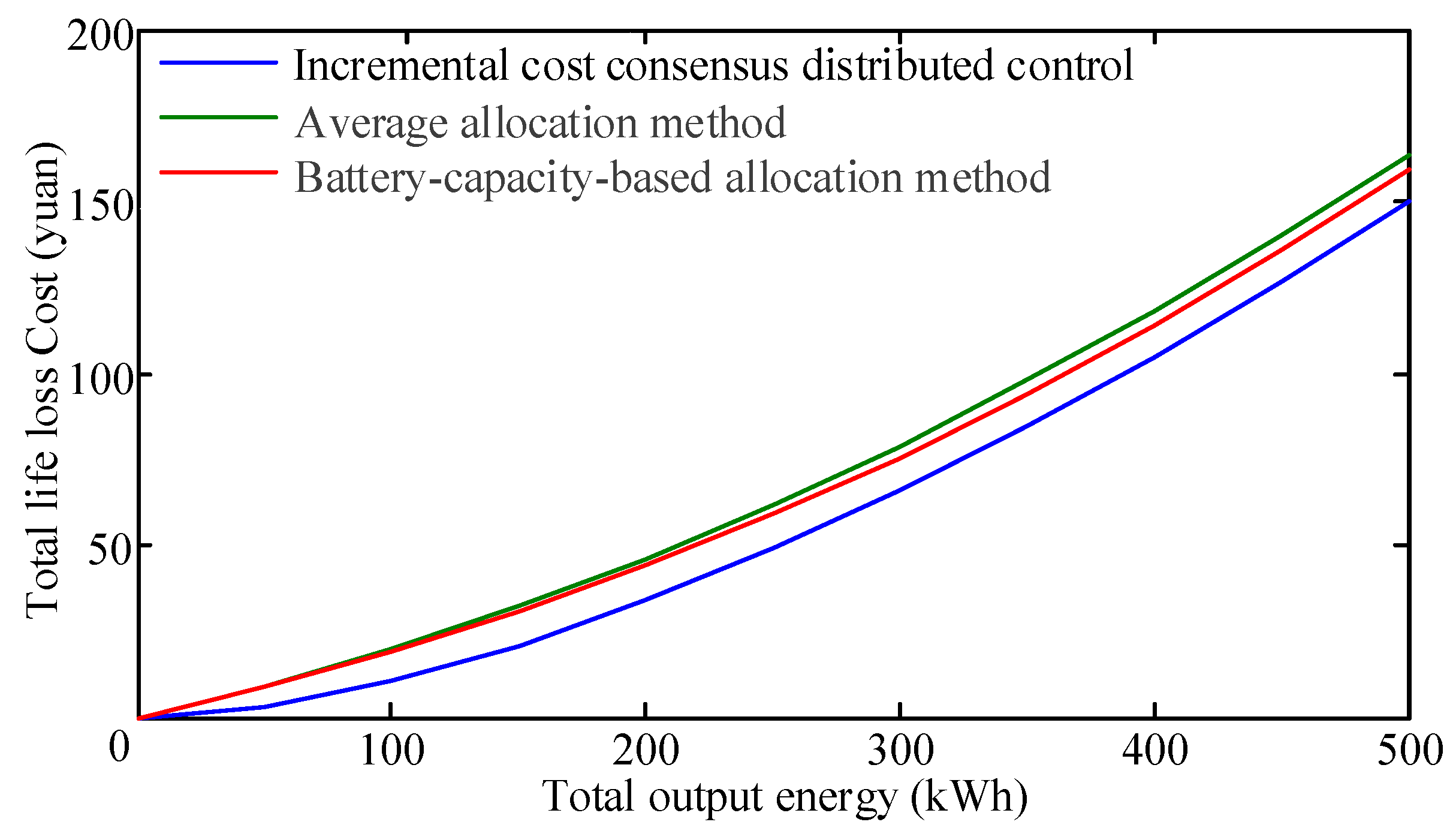
The coefficients of the life loss cost function of batteries have a certain random distribution characteristic when considering the difference among EVs and user habits. We assumed that the coefficients of the life loss cost function were normally distributed. The relationship between the total life loss cost
Fagg and the total output energy
during the release process could be obtained as shown in
Figure 2.
It can be seen from
Figure 2 that the total life loss cost and the output energy approximately follow that of a quadratic function. The least squares method was used for fitting the relationship between the life loss cost and the output energy of the cluster in order to establish the cost function model of the MESC. The fitting function is shown as follows:
where
α,
β and
γ represent the coefficients of the above quadratic function. The cost function curve of the MESC will serve as the basis for implementing the distributed control strategy in the upper layer.
3.2. Upper Layer Control Strategy
In order to apply the multi-agent consensus algorithm to the MESS, the reasonable allocation of energy between BESCs is coordinated and the minimum total cost of BESS is guaranteed. The definition of the incremental cost
λagg,i of cluster
i is represented as follows:
where
i is the index of the MESC,
Fagg,i denotes the total life loss cost of cluster
i,
Qagg,i is the amount of output energy released by cluster
i and
Iagg,i is equal to the incremental cost
λagg,i during the operation of the consensus algorithm.
The incremental cost consensus algorithm aims to minimize the total cost of the system while the state of all nodes tends to be consistent. The consensus variable
λagg,i can be obtained by using Equations (10) and (11), which is shown as follows:
The non-leader node interacts with each other following Equation (13):
where
Nagg represents the total number of clusters,
λagg,j represents the information state of cluster
j that is adjacent to cluster
i,
hij is the element in the sparse iterative matrix
H and the sparse iterative matrix is obtained from the Laplacian matrix corresponding to the communication topology [
18].
As seen by Equation (13), the current energy information of each battery can be obtained using the incremental cost,
Qagg,i, which can be calculated by:
Additionally, Δ
Q is defined to indicate the mismatch between the total energy demand of MESS and the overall output energy of all the clusters in order to satisfy the energy balance constraint of the clusters, which is expressed as below:
where
QDagg represents the total energy demand of MESS and
Qaggmin,i and
Qaggmax,i are the maximum and minimum output energy, respectively, that each cluster can provide.
The updated rule for the leader node is shown as follows:
where
ε is the convergence coefficient and is related to the convergence speed of the leader node. The convergence rate of the consensus algorithm is related to the topology of the system communication network. ∆
Q is a sign that
λ increases or decreases. If ∆
Q > 0, it means that more energy needs to be offered by the energy storage system and the current
λagg should be increased, and vice versa.
In the consensus iteration process,
Qagg,i is subject to the following constraint:
By following the updated rules described by Equations (13)–(18), λagg,i will asymptotically converge to Iagg.
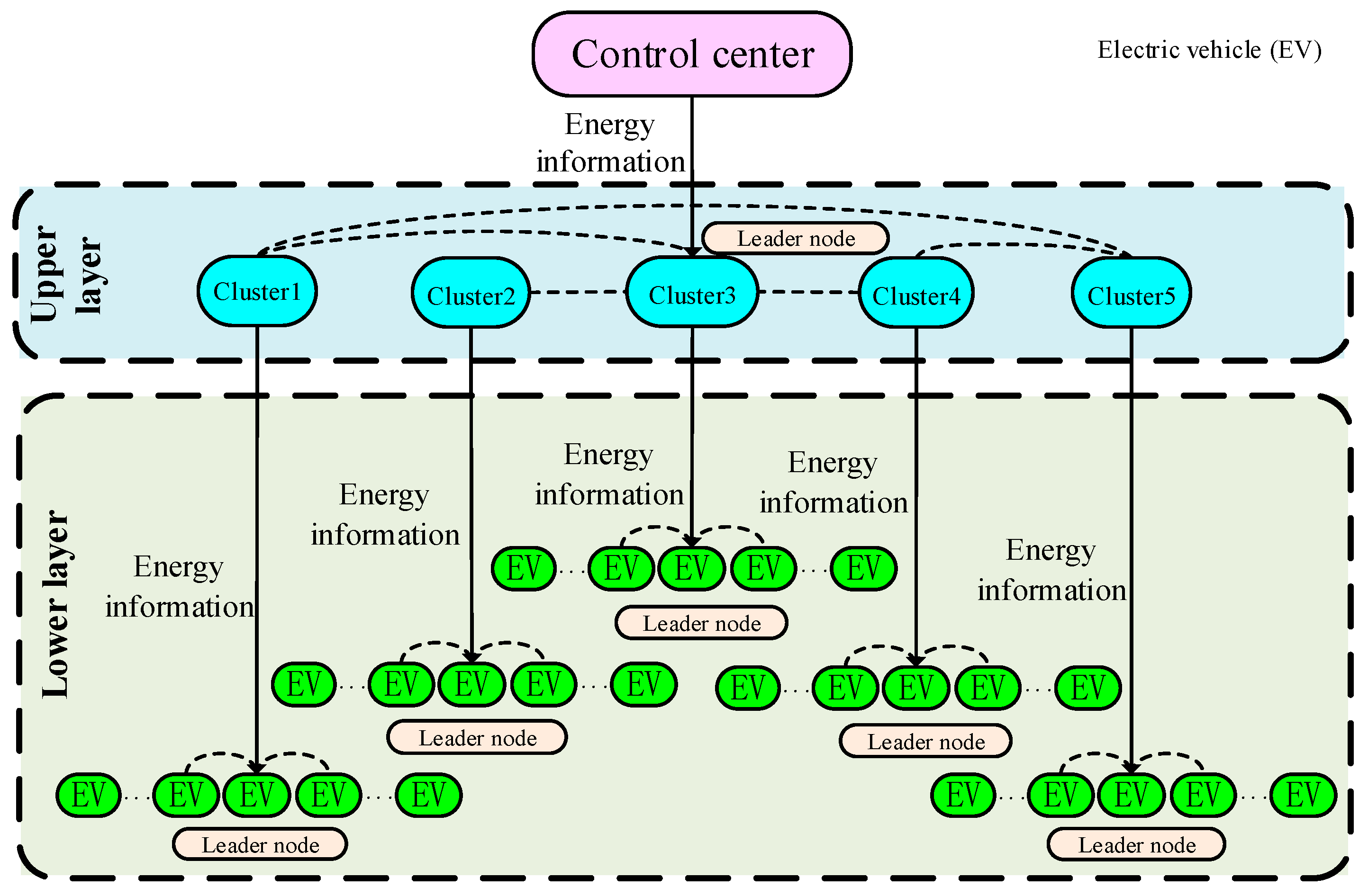
The flow chart of the hierarchical distributed collaborative control strategy is shown in
Figure 3. When the scheduling command is issued, the control center sends the energy information to the leader node in the upper layer, and the MESCs can realize the optimal allocation by running the consensus algorithm. After energy allocation is completed in the upper layer, each cluster then sends the energy information obtained by itself to the leader node of the lower layer to allocate the energy among EVs. In each iterative process of the consensus algorithm, the non-leader node only needs to apply the consensus algorithm and guarantee the constraint condition. However, in addition to implementing the above process, the leader node also needs to determine whether the balance condition of Equation (15) is satisfied. If the total energy offered by the MESS is equal to the amount of energy demanded (
), the consensus algorithm is finished and each MESU releases energy according to the information currently obtained by itself, otherwise the consensus algorithm continues to run until the conditions are satisfied.
4. Simulation Results
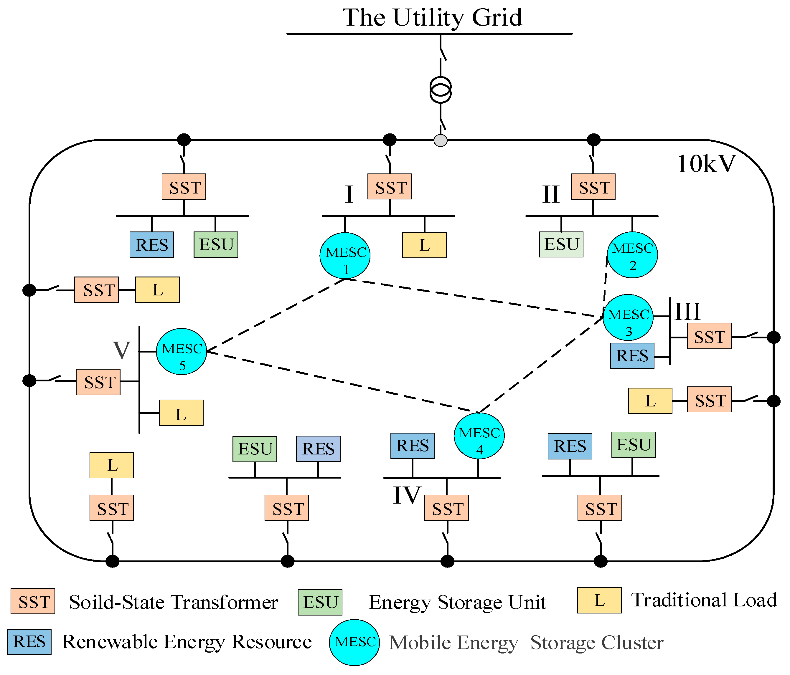
Based on the FREEDM microgrid system [
19], this paper constructed a distributed energy storage system as shown in
Figure 4, and validated the proposed distributed consensus control strategy. MESCs were separately connected to bus I, II, III, IV and V. The dotted line in
Figure 4 indicates the communication connection between the clusters. The types and quantities of EVs in each cluster are shown in
Table 1.
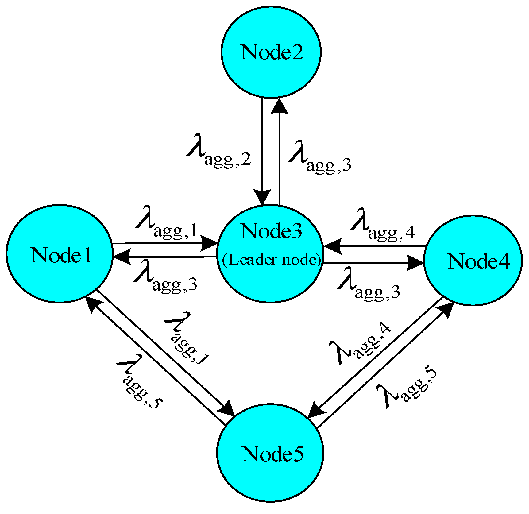
By using the consensus algorithm and selecting the incremental cost of the cluster as the consensus variable, the dispatch problem can be solved in a distributed manner.
Figure 5 shows the communication topology of the five-MESCs system, in which node 1~5 corresponded to cluster 1~5 in
Figure 4. The incremental cost
λagg,i of cluster
i will be updated based on its neighbors’ incremental costs. In addition, the leader node has to be selected, which will control whether to increase or decrease the group incremental costs. In the example shown in
Figure 5, node 3 was selected as the leader node of the five-MESCs system according to the centrality principle [
20].
An assumed topology of the EV charging piles in each node is shown in
Figure 6, where the dotted line indicates the communication connection and each charging pile can exchange information with four adjacent charging piles (two left and two right). BYDe6 and Tengshi 2017 EVs use Li-ion batteries as energy storage batteries, and their capacities are 82 kWh and 62 kWh, respectively. The initial investment cost of the battery is 1300 yuan/kWh.
The above information was used to construct an aggregated model. Methods for allocating output energy of EVs adopt three allocation methods: the optimal allocation method based on the consensus incremental cost, the average allocation method and the battery-capacity-based allocation method. The coefficients of the function of the aggregated model are shown in
Table 2,
Table 3 and
Table 4 for each allocation method, respectively.
Assuming that a lack of energy occurred at t = 0 s, a scheduling command was issued, which was required to supply energy about 500 kWh to the system in a short time.
Firstly, the hierarchical distributed cooperative control strategy proposed in this paper was tested. After receiving the scheduling command, the five-MESCs system realized the optimal allocation of the output energy in the upper layer through the distributed control. Then, after the nodes in the lower layer received the energy information, the output energy was allocated by the corresponding allocation strategy. A fixed step size of 0.02 s and a convergence coefficient of
ε = 0.00005 were used. It is worth mentioning that the aggregated model of the MESC was modeled based on the three allocation methods given in
Section 3.1: the optimal allocation method based on consensus incremental cost, the average allocation method and the battery-capacity-based allocation method. The related simulation results are shown in
Figure 7 and
Figure 8.
Figure 7 and
Figure 8 indicate that the system reached a steady state in a short time. At the same time, the energy storage clusters could realize the optimal energy allocation according to the distributed control strategy. No matter which method was used, energy can be efficiently allocated to each node in the upper layer with its optimal cost.
The information of each node under different energy allocation methods is shown in
Table 5.
It can be observed in
Table 5 that the batteries that adopted different allocation methods in the lower layer led to a different output energy in the upper layer. However, the total energy demanded by the system was unchanged, so the total output energy was equal to the energy required by the system. Eventually, the amount of output energy scheduled by each EV could be obtained by calculations.
The life loss cost under different allocation methods are shown in
Table 6. As shown in
Table 6, the overall life loss cost of the five-MESCs system was at its minimal when adopting the optimal allocation based on the consensus incremental cost method.
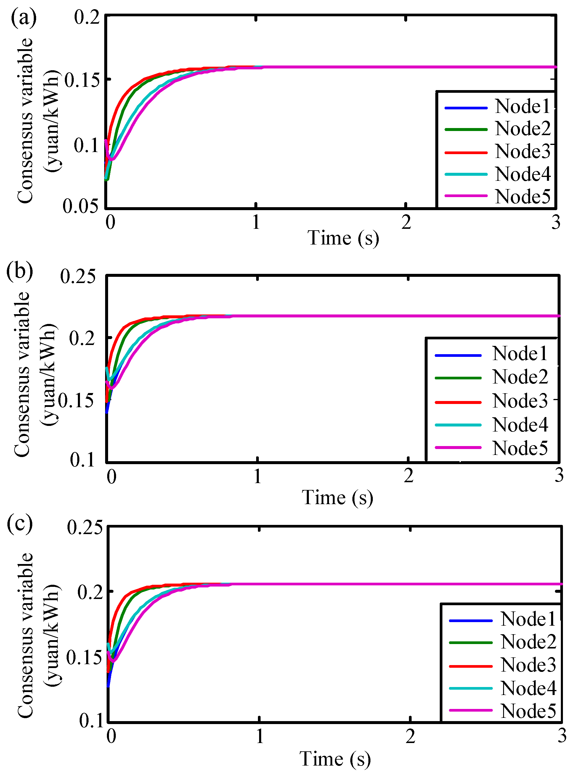
After the energy allocation in the upper layer was completed, the energy allocation among EVs in the lower layer was performed. For example in cluster 4, the corresponding output energy was 111.3019 kWh and that corresponds to
QD = 111.3019 kWh. The simulation curves are shown in
Figure 9 and
Figure 10 using the communication topology in
Figure 6.
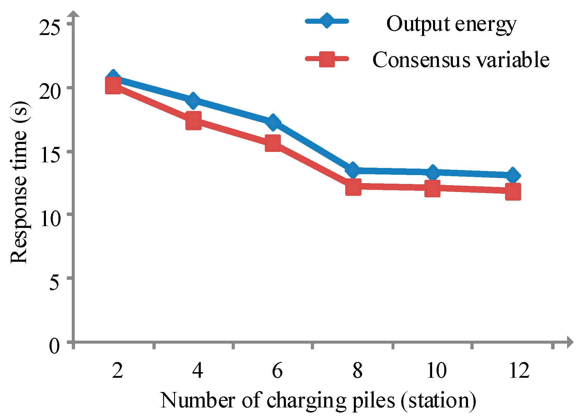
In the above example, each EV charging pile only exchanged information with four adjacent charging piles. If the information interaction capability changes, it will affect the communication topology and the final response time. With the enhancement of the wireless communication capability, each charging pile can exchange information with more adjacent charging piles based on the charging piles distribution structure shown in
Figure 6, which leads to a change in the communication topology. The relationship between response time, consensus variable and output energy under different communication capabilities is shown in
Figure 11, where the number of charging piles that can exchange information reflected the communication capability.
As shown in
Figure 11, the system converged to the target value more quickly and responded more quickly to the scheduling command with the enhancement of the wireless signal communication capability. However, when the number of charging piles were more than eight, there was no significant change in the response time with increasing number of charging piles.
In order to illustrate the superiority of the hierarchical control, the following examples adopted the non-hierarchical control method to allocate energy to all EVs. Compared with the hierarchical distributed control method, all EVs directly participated in energy allocation, which made the structure of the system more complicated, resulting in a slower convergence of the consensus algorithm in the iterative process and a longer time to reach optimal results. The simulation curves are shown in
Figure 12 and
Figure 13.
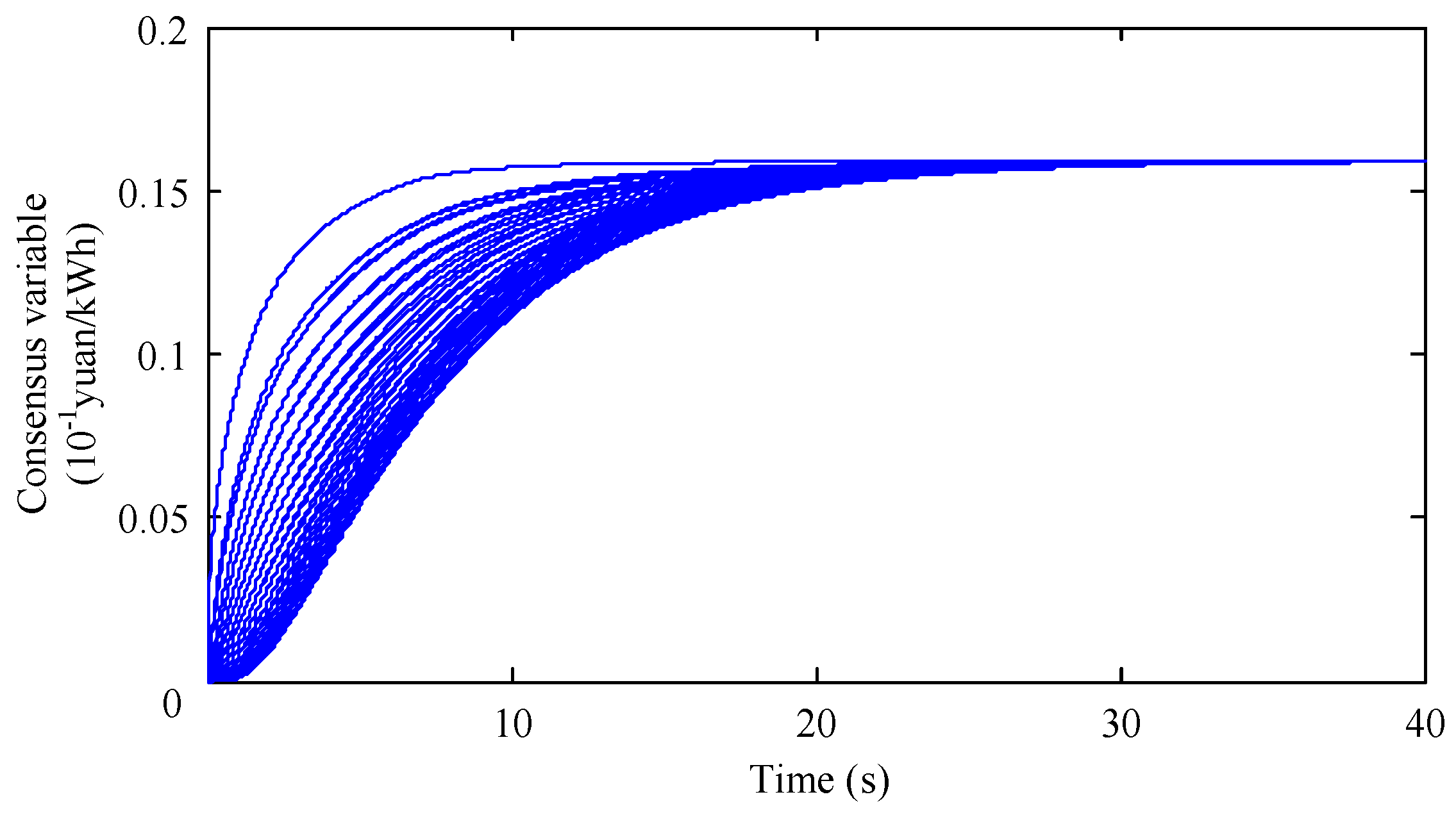
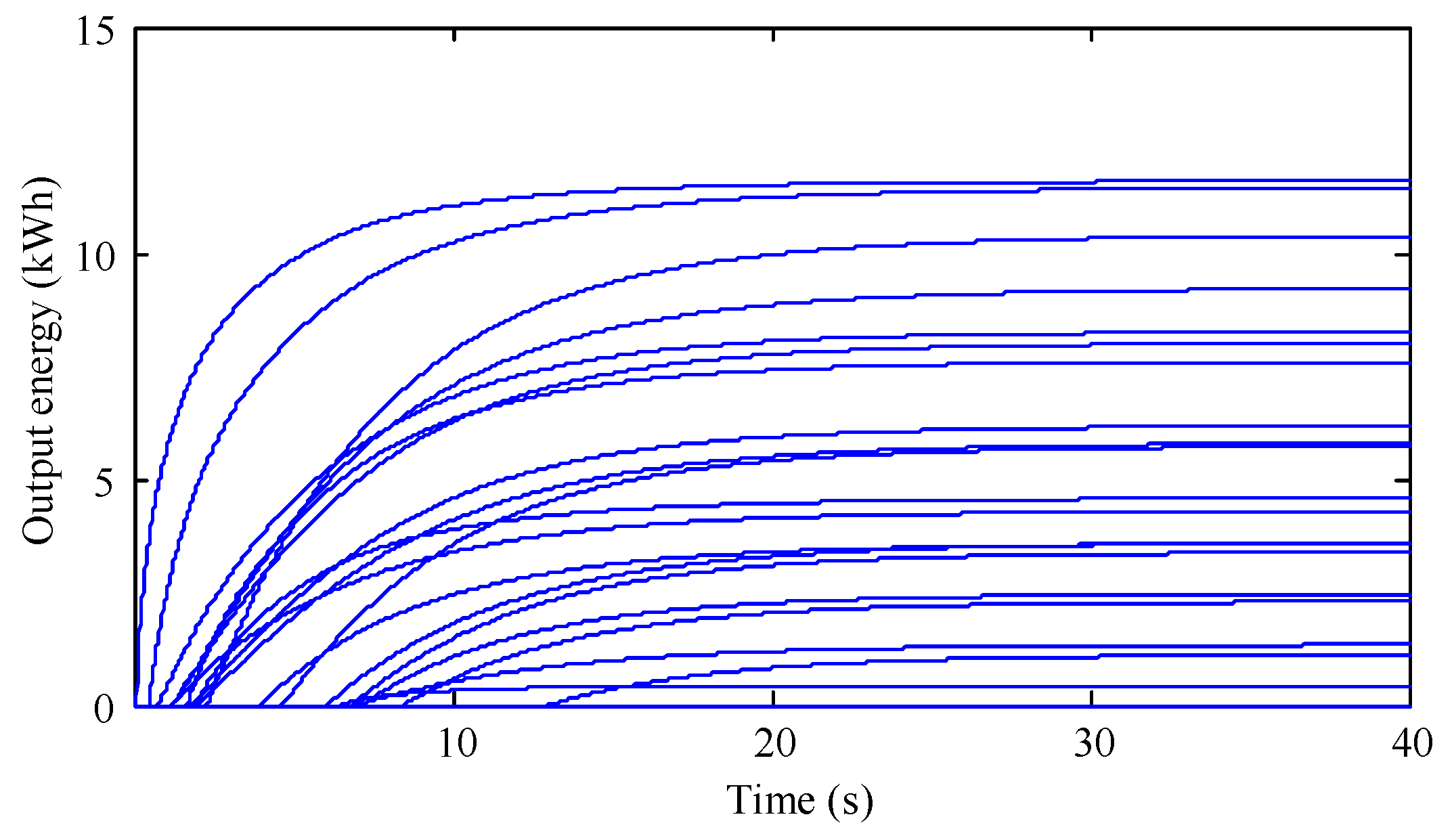
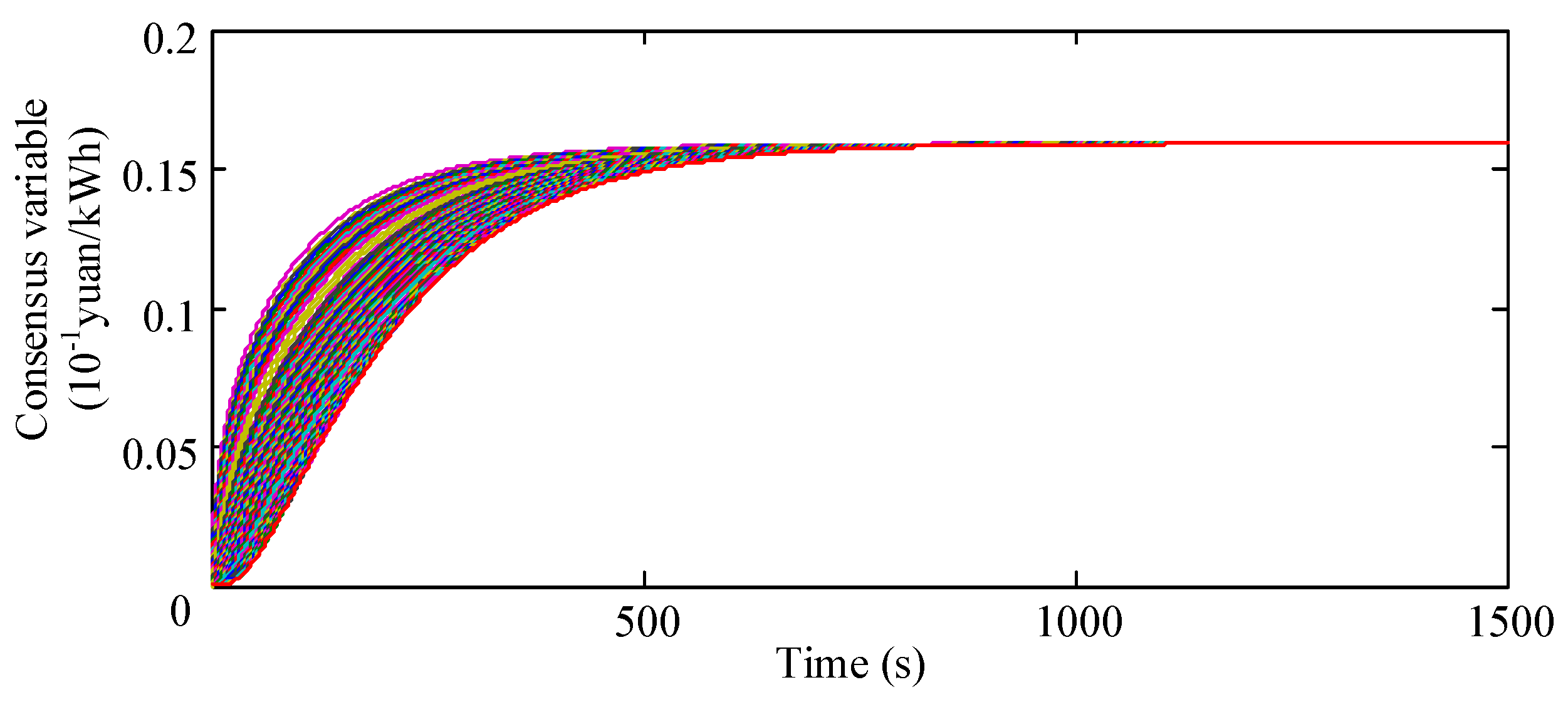
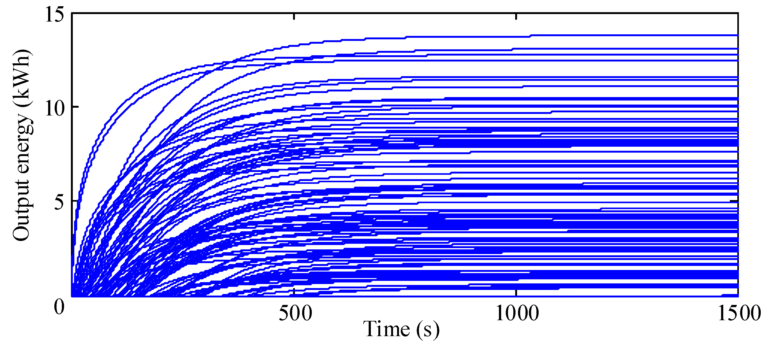
Figure 12 and
Figure 13 show the curves of the consensus variables and output energy of all EVs in the system while adopting the non-hierarchical control method. As shown in
Figure 12, the time taken for the consensus variable to converge to the optimal value reached 800 s when the non-hierarchical control was adopted. According to the curves of the output energy shown in
Figure 13, the system scheduling cost was about 47.56 yuan. Although the overall cost was slightly reduced, the total response time under the hierarchical distributed control method (
Figure 7 and
Figure 8 and
Table 6) was less than 5% of that when the control was non-hierarchical.


 ,
, 


