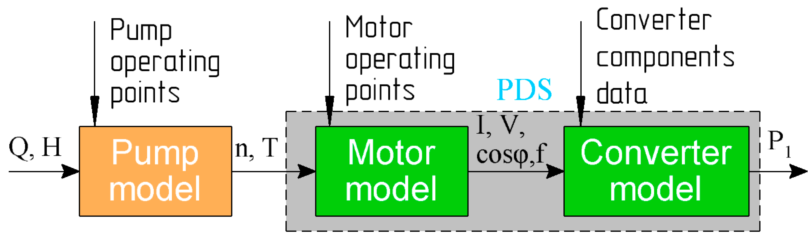
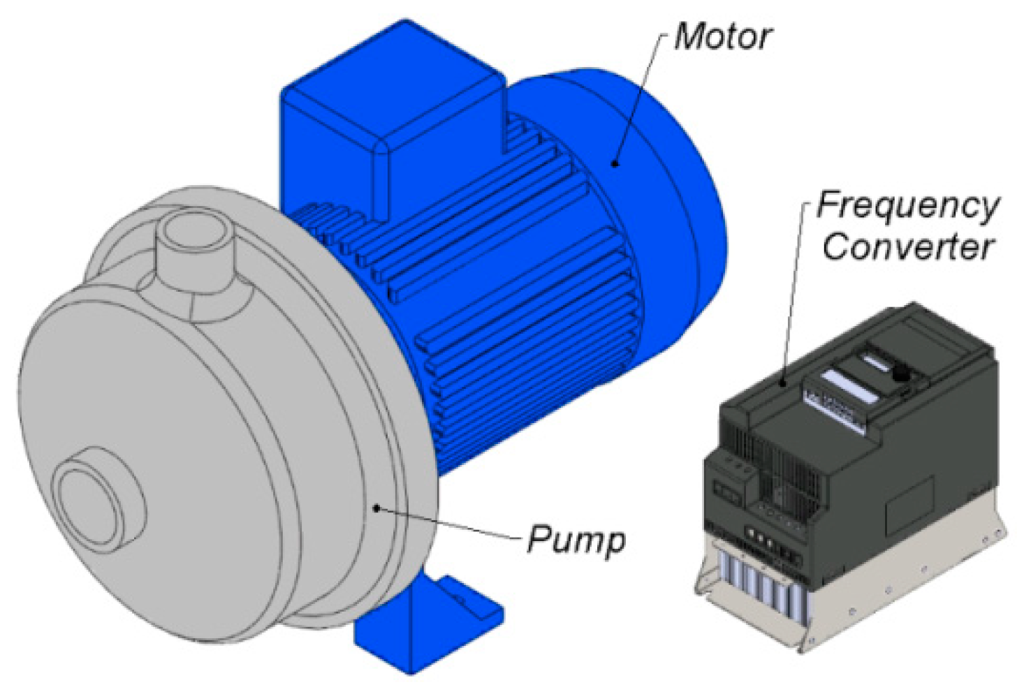
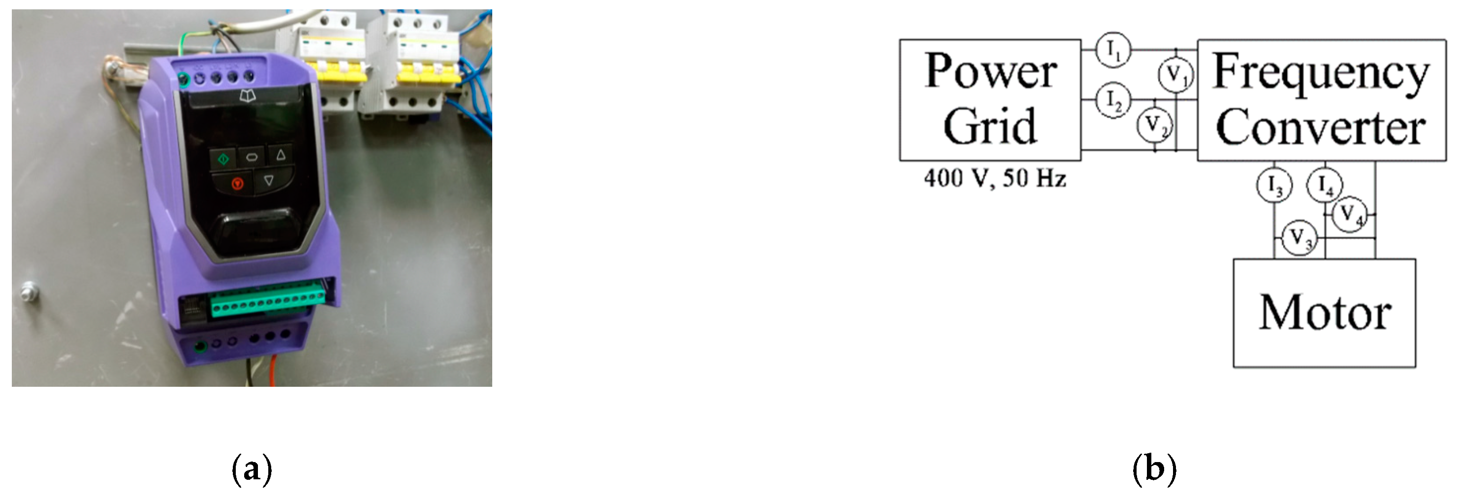
The complete structure of the investigated system consists of the pump, motor and the frequency converter as sketched in
Figure 1 and
Figure 2. In order to compute the
T-n (torque-speed) characteristics of the pump unit, the hydraulic load settings, which are the fluid flow rate (
Q) and the hydraulic head (
H), are necessary. Using those load settings, the input power of the pump can be known, hence the required motor output power. Eventually, using the solution of the complete drive models, the input power from the grid to the converter can be obtained, resulting in an estimation for the losses. Notice that, the direction of the arrows in
Figure 1 shows the direction of the input power calculation. However, the direction of the power flow is of course starting from the grid (
P1) to the load. Two types of electric motors to drive the pump are considered in this study: the induction motor (IM) and the synchronous reluctance motor (SynRM), having a rating output power of 1.1 kW.
2.2. Evaluation of the Motor Performance
In this section, the methodology for the performance assessment of the IM and the SynRM as a part of the pump unit is presented. The examined machines are of the general-purpose type, with the rated power and speed of 1.1 kW and 3000 rpm respectively. Both the IM and the SynRM have a similar housing. The IM is a commercially motor of IE3 class. The SynRM prototype of reference [
24] is used. More detailed data of the motors are presented in
Table 3.
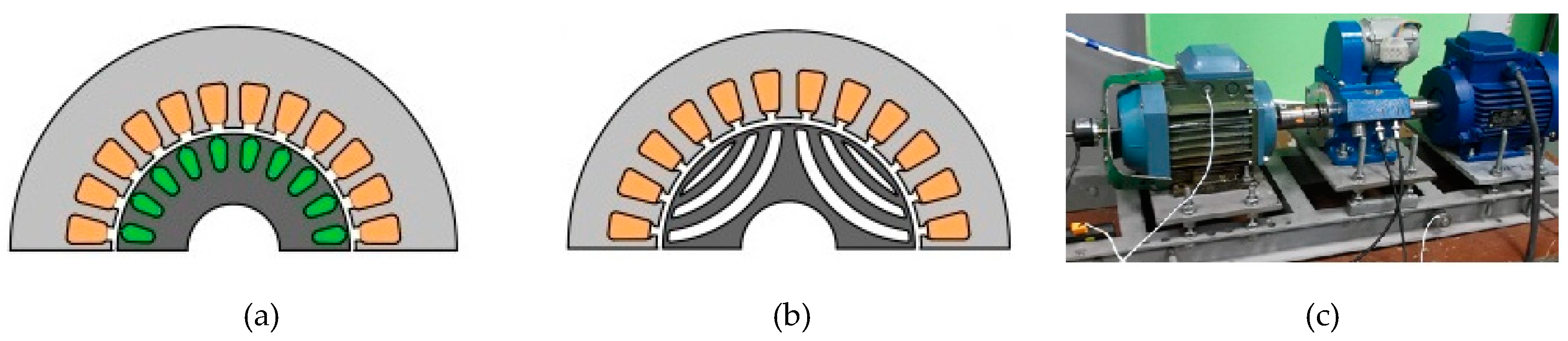
Figure 3a,b shows a sketch for the motors geometry.
Due to the slip, the IM has the rated speed 2875 rpm (not 3000 rpm) and the rated torque of 3.65 N∙m (not 3.5 N·m) according to its nameplate. However in this study the IM was tested as a motor with rated values of 1.1 kW and 3000 rpm; this is done using the control system.
Electrical parameters of the motors are presented in the table. Parameters of the SynRM were measured during the tests. Parameters of the IM were calculated on the basis of the manufacturer’s test report [
25].
The number of poles is 4 for SynRM however, IM of 2 poles used because a general purpose frequency-controlled 4-pole IM with the rated speed of about 3000 rpm is still a very rare product on the market. If 4-pole IM is used compared to 4-pole SynRM, the difference in efficiency of the motors would be lower than using 2-pole IM.
The motor characteristics in the required operating modes (
Table 2) are estimated based on experimental measurements according to IEC 60034-30-2. The motors are tested when they were powered by FCs, using the "direct" method, according to reference [
26]. The switching frequency of the inverter is 4 kHz, which is a standard switching frequency range for testing motors of the low rated power range [
26]. The standard voltage/frequency (
V/f = constant) control method is used while testing the IM [
5]. Notice that the efficiency of the IM could be a slightly better in the underload operating points in case of applying a more comprehensive control strategy with a flux optimization method than the voltage/frequency (
V/f = constant) control. However, the voltage/frequency (
V/f = constant) strategy is the most widespread case in the industry. The SynRM is driven using a sensorless control method provided by the serially produced FC of reference [
27]. In both motors, a given constant torque reference of the load machine was set during the test. A mechanical speed value needed was achieved by adjusting the frequency reference of a tested motor.
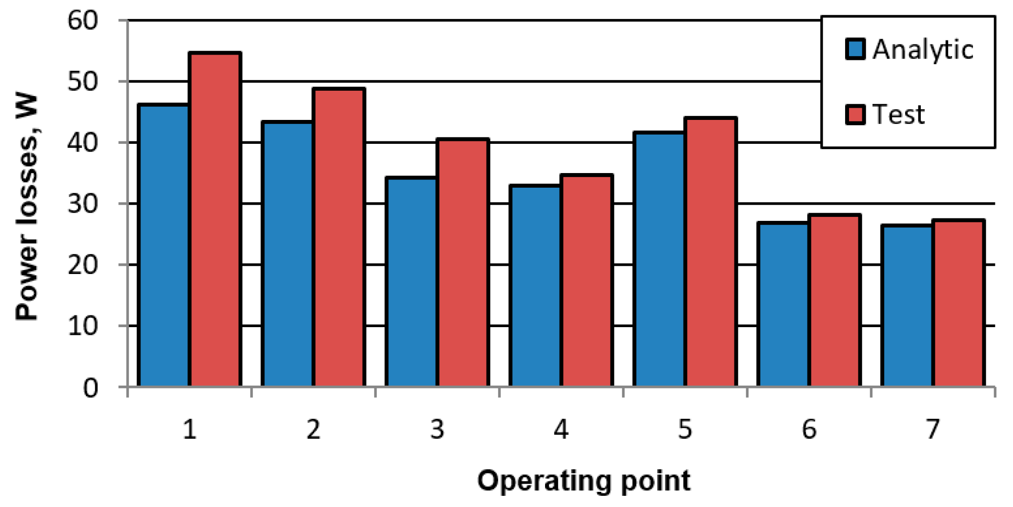
Figure 3c shows a photograph of the experimental test bench. In this work, to provide a correct comparison between the energy characteristics, the losses of the IM and the SynRM drives were interpolated using the standard method IEC 60034-30-2 when they are powered by a frequency converter. The obtained experimental measurements of the IM and the SynRM are listed in
Table 4 at several operating points of speed and torque.
The IEC 60034-30-2 standard requires manufacturers to declare motor efficiency values at 7 operating points (
Table 4). Some manufacturers provide such data in their catalogues [
28]. However, the measurements given in
Table 4 demonstrate that only
ηmotor data is insufficient for calculating the losses in the FC and in the drive as a whole. It is also necessary to know the current and power factor. To deal with this problem, the IEC 61800-9-2 standard proposes making look-up tables with loss values in CDM depending on “relative torque producing current (
Ir, torque)” and “relative motor stator frequency”, as well as reference tables with
Iout (
Ir, torque,
Sr, equ) and cosφ (
Ir, torque,
Sr, equ); where
Sr, equ is the rated apparent power of the CDM [
5]. However, this solution is applicable only for calculating the efficiency of a drive with IM having typical parameters. To apply this approach to other types of motors (in particular to SynRM), it is necessary to compile reference tables
Iout (
Ir, torque,
Sr, equ) and cos
φ (
Ir, torque,
Sr, equ), that are applicable with sufficient accuracy for each type of motor.
Consequently, we propose a more general and accurate approach using the 7 standard points of
Iout and cos
φ values obtained during the tests in addition to the data on the
ηmotor. The inclusion of these data in the motor technical documentation does not require additional tests, besides those necessary for measuring motor efficiency at 7 points, according to IEC 61800-9-2. As this is already specified for
ηmotor [
28], the manufacturers can declare the values of
Iout and cos
φ at no additional cost in the technical documentation. Therefore, this approach could be promising.
Moreover, the obtained measurements of
Table 4 are used to calculate the coefficients of second order interpolating polynomials
f (
T,
n), according to [
5,
23]:
where
A is the 7 × 1 coefficient vector to be found;
X is the 7 × 7 variable (
T and
n) matrix;
B is the 7 × 1 answer vector (for example it may consist of given values of motor current). As such, the value of a considered operating characteristic of the motor can be found by:
where
b(
T,
n) is the variable value to be found (motor current, efficiency or power factor);
a1 to
a7 are the elements of the coefficient vector
A.
The calculated motor performances obtained on the basis of data in
Table 4 using the interpolation procedure (2) for the pump operating modes under consideration (
Table 2) are presented in
Table 5.
Table 4 and
Table 5 have the following designation for motor characteristics:
Iout is the RMS phase current;
Vout is the RMS phase voltage; cos
φ is the power factor;
P1ph is the phase active power;
f is the electrical frequency of the fundamental harmonic;
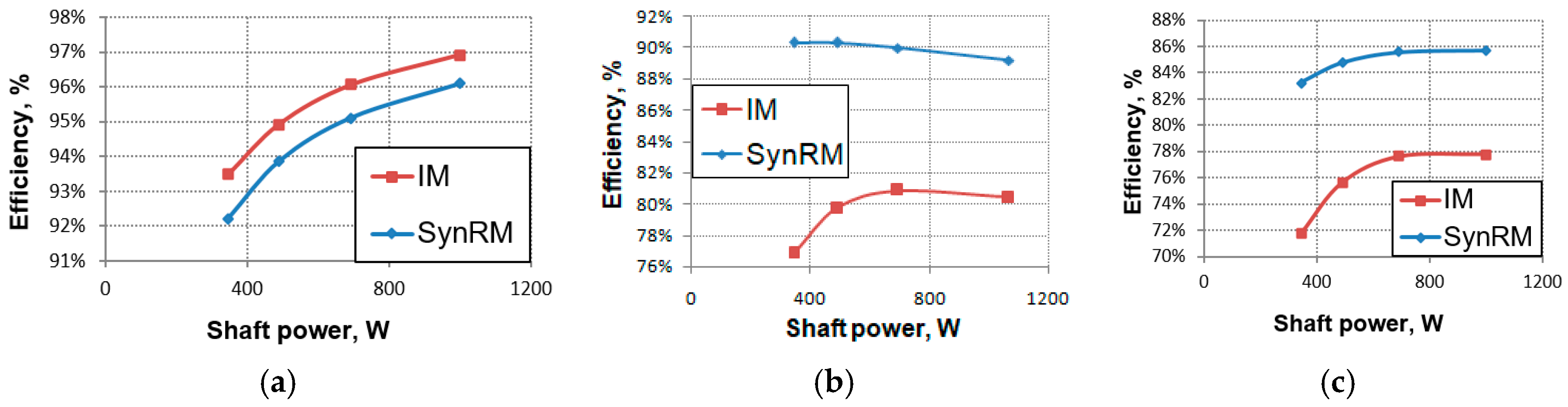
ηmotor is the motor efficiency. It can be noted that the value of
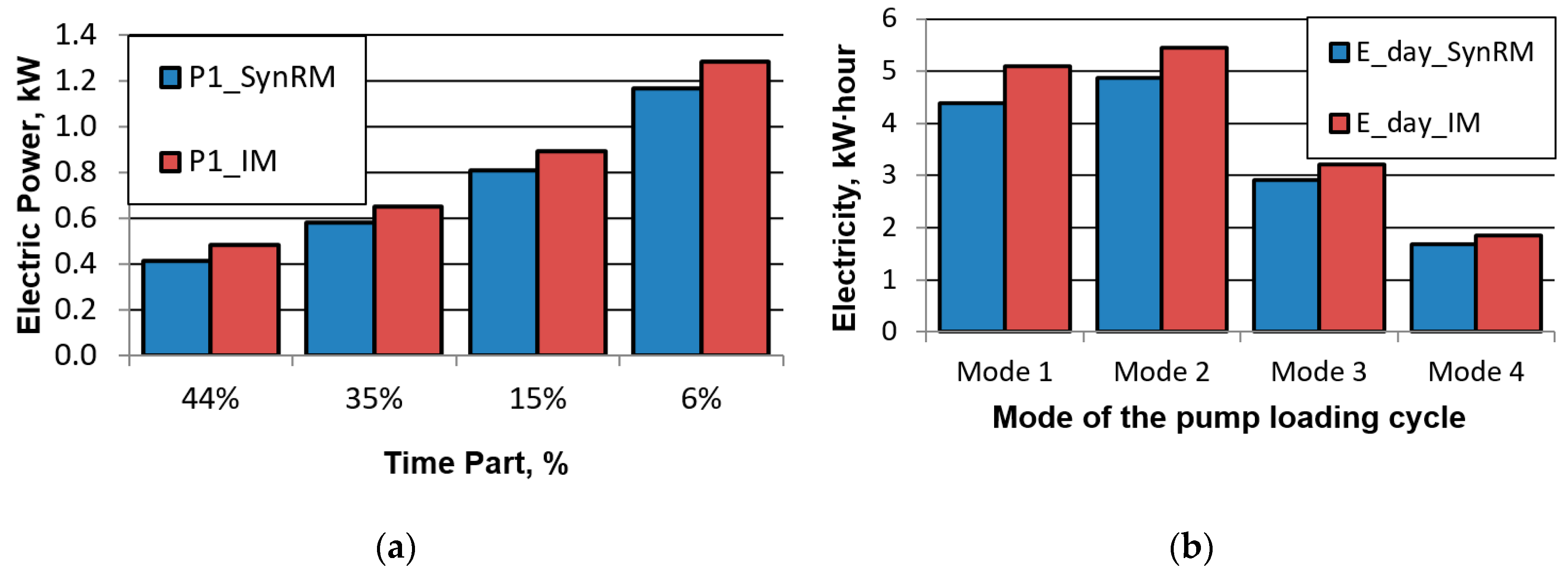
ηmotor for SynRM in all the considered modes is higher than that of IM.
In this case the motor cos
φ is calculated as the following:
where
Vrms line fund is the RMS value of waveform of the measured motor line voltage averaged over the PWM period.
In addition,
Table 5 shows performance of the motors when loaded by the pump at the given conditions of
Table 2. Notice that the frequency values
f of the IM are calculated without taking the rotor slip into account. This is an assumption of the proposed method. But it does not produce a significant error in the computed losses of FC.
Using Equation (2) for mode No. 4 in
Table 2, we obtain the following results:
Iout = 2.344 A,
Vout = 231 V, cos
φ = 0.761,
P1ph = 412 W. However, it must be taken into account that the actual maximum output voltage of FC is slightly lower than the theoretical limitation given by the inverter modulation index.
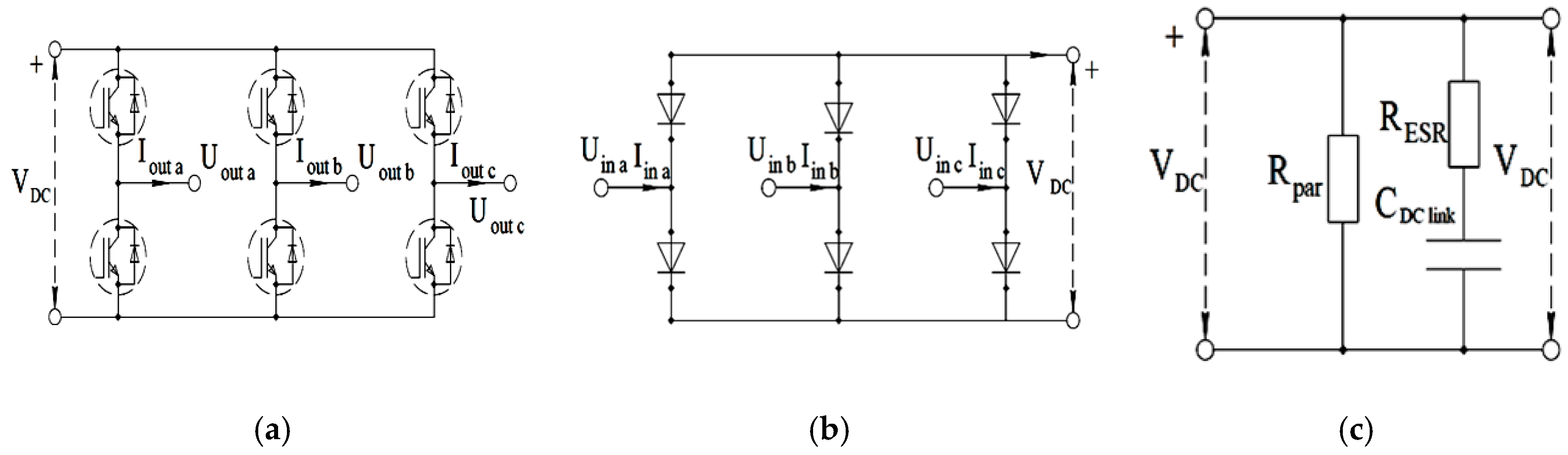
The modulation index for the inverter for the case of the space vector modulation (SVM) is calculated by [
17,
18]:
where
Vm phase fund = √2∙
Vout is the amplitude of the modulated phase voltage of the load;
VDC is DC-link voltage.
The theoretical maximum value is
m = 1 without over modulation. The maximum value of the RMS line voltage is [
17]:
In this work, all calculations are conducted for the case of the symmetrical space vector modulation. Thus, if
VDC equals 565 V, then the theoretical maximum effective linear voltage is 400 V and the limitation of phase voltage is 231 V. However, there are additional hardware limitations of maximum PWM duty cycle due to the presence of dead time and the restricted switching speed of IGBT drivers. Therefore, the maximum modulation index of the FC that was under testing in this work is about 97%. Considering this, we assume
Vout = 0.97 ∙ 231 = 227.8 V in mode No. 4 for IM. In addition, according to reference [
5], an increase in IM losses caused by the FC voltage drop (motor de-fluxing) was calculated:
where
Vout is the value of motor voltage obtained using (2);
Pmotor loss =
P1−
P2 is the value of motor losses obtained using (2);
Vout max CDM = 227.8 V is the maximum output CDM voltage.
The increase in motor losses also causes an increase in cosφ. With this we assume that the value of Iout remains the same since there is not only an increase in the active component of the current but also a decrease in the reactive component.
To compare the cost of the considered motors,
Table 3 shows an estimation of the mass and the cost of the active materials. It is observed that the costs are comparable. In addition, SynRM does not have a cast squirrel cage in the rotor, therefore its production technology is cheaper than that of IM.

 ,
, 


