Article

Investigations on the Performance of a New Grounding Device with Spike Rods under High Magnitude Current Conditions

by
Abdul Wali Abdul Ali
,
Nurul Nadia Ahmad
,
Normiza Mohamad Nor
*,
Muhd Shahirad Reffin
and
Syarifah Amanina Syed Abdullah
Faculty of Engineering, Multimedia University, Cyberjaya 63100, Malaysia
*
Author to whom correspondence should be addressed.
Energies 2019, 12(6), 1138; https://doi.org/10.3390/en12061138
Submission received: 26 February 2019 / Revised: 20 March 2019 / Accepted: 21 March 2019 / Published: 23 March 2019
(This article belongs to the Special Issue High Voltage Engineering and Applications)

Abstract

:
In many publications, the characteristics of practical earthing systems were investigated under conditions involving fast-impulse currents of different magnitudes by field measurements. However, as generally known, in practice the transient current can normally reach several tens of kiloamperes. This paper therefore aimed to investigate the characteristics of a new electrode for grounding systems under high current magnitude conditions, and compare it with steady-state test results. The earth electrodes were installed in low resistivity test media, so that high impulse current magnitudes can be achieved. The effects of impulse polarity and earth electrode’s geometry of a new earth electrode were also quantified under high impulse conditions, at high currents (up to 16 kA).

1. Introduction

Much work [1,2,3,4,5,6,7,8,9,10,11,12,13,14,15,16,17,18] has been carried out to characterize practical earthing systems under fast-impulse, high-magnitude current conditions. As generally known, experimental investigations on practical earthing systems under high impulse currents can provide more realistic results on the characteristics of earthing systems under high currents, in comparison to laboratory and computational methods. The first work on impulse characteristics by field measurement was carried out by Towne [1] in 1928, on galvanized-iron pipes with peak currents up to 900 A. In 1941, Bellaschi [2] had used deep-driven earth rods with current magnitudes between 2 kA to 8 kA. The following year, Bellaschi [3], completed further tests on 12 earth rods, with impulse currents of 400 A to 15.5 kA. There have been a lot more impulse tests [4,5,6,7,8,9,10,11,12,13,14,15,16,17,18], were carried out on practical earthing systems, where tit was found that the ‘impulse resistance’ values were found to be less than those measured for low voltage, low frequency currents [1,2,3,4,5,6,7,8,9,10,11,12,13,14,15,16,17,18]. A lot of improvements and suggestions in the impulse test methodology on practical earthing systems can also be seen in the last three decades [1,2,3,4,5,6,7,8,9,10,11,12,13,14,15,16,17,18]. Impulse tests have also been carried out on practical earthing systems considering various factors, namely; earth electrode geometry, soil resistivity, impulse polarity and voltage/current magnitudes [1,2,3,4,5,6,7,8,9,10,11,12,13,14,15,16,17,18]. For the study of grounding performance with the current magnitudes up to 5 kA, limited studies have been carried out on the effect of the earth electrode’s configuration. A remarkable work was done in [4,5,6], where impulse tests were conducted on various practical earthing systems, with current magnitudes of more than 20 kA. It was found that the impulse resistance becomes less current dependent in high currents. For the effect of soil resistivity, it was reported in [19,20] that in a low resistivity test medium, it is possible that no ionization process occurs in the test since the gaps between the sand grains are filled with water, and little field enhancement is expected to occur since there is only a small dielectric difference between the soil and the air gaps. In addition, this could also be due to the fact the earthing systems may have become a conducting mass in low resistivity soil.
As for the effect of impulse polarity, as early as 1948, Petropoulos [21] found that for similar electrode dimensions and soil resistivity, the critical electric field, Ec which is the onset of ionization, and the breakdown voltage were found higher for negative compared with positive impulses. A few more studies followed with investigations on soil characterisation under high impulse current for both impulse polarities, where most of the studies were done by laboratory testing [19,20]. In the last few years, a few studies can be found on the effect of impulse polarity on practical earthing systems under high impulse conditions [17,19]. Since very limited studies can be found on the effect of impulse polarity on various grounding system configurations for the same soil resistivity, this paper presents the experimental results on new earth electrodes, combined with various electrode’s configurations, under both impulse polarities.
This paper reports the investigation on the performance of a new grounding electrode, called a grounding device with spike rods (GDSR) under high-magnitude fast impulses, of both impulse polarities. The reason GDSR was designed and studied in the current paper is to follow up on the study performed by Petropoulos [21], where he found that electrodes fitted with spike rods have lower resistance than that electrode without the spike rods. For these reasons, further studies were performed, and presented in this paper. He [21] described the high field intensity of the spike rods which causes more current to flow. In this current work, it was realized and evident by field testing and measurements, which have not been implemented before. GDSR was also combined with other electrodes, which were installed at one site. A smaller impulse generator was also employed to observe the effectiveness of GDSR combined with other electrodes in the same soil resistivity at lower current magnitudes, below 2 kA. A new grounding electrode with spike rods was postulated to enhance the ionization process in soil and compared with conventional rod-electrodes. It was shown the resistance becomes less current dependent at high currents, which was found to be agree with previously published works [2,3,4,5,6,7,8,9,10,18,19,20,21].

2. Experimental Arrangement

In this study, eight earth electrode configurations were installed at the same soil site. Using the Wenner method, the soil resistivity of the outdoor test site was measured with earth tester. The RESAP module of Current Distribution, Electromagnetic Fields, Grounding and Soil Structure Analysis (CDEGS) was used to interpret the measured data into 2-layer soil models. The test site was purposely selected at a farming land, to obtain for low soil resistivity result, hence high current magnitudes can be achieved. It was computed that an upper layer and lower layer resistivity of 2.95 Ωm and 0.23 Ωm, respectively with 4.9 m depth for upper layer, and an infinite depth for lower layer.

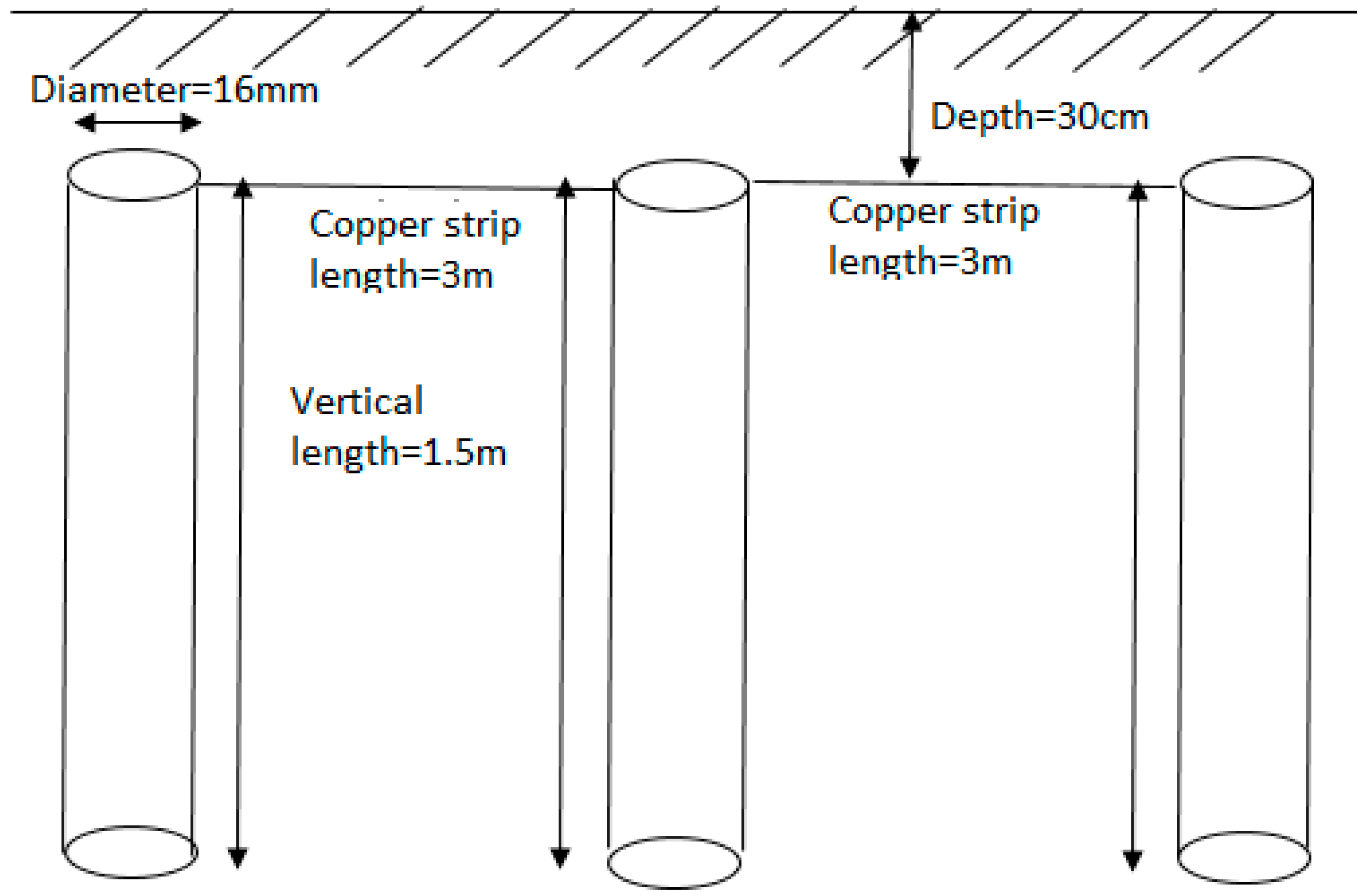
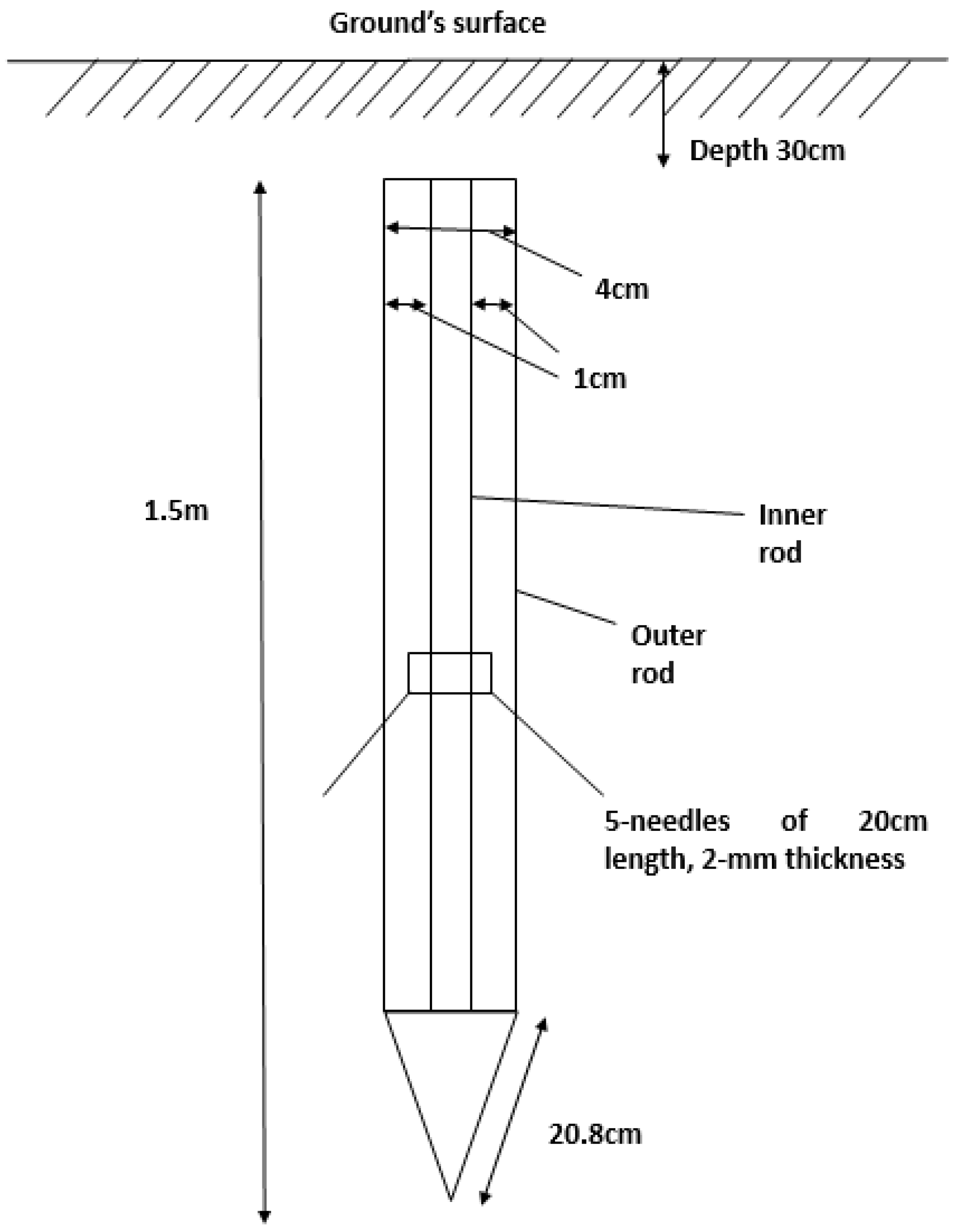
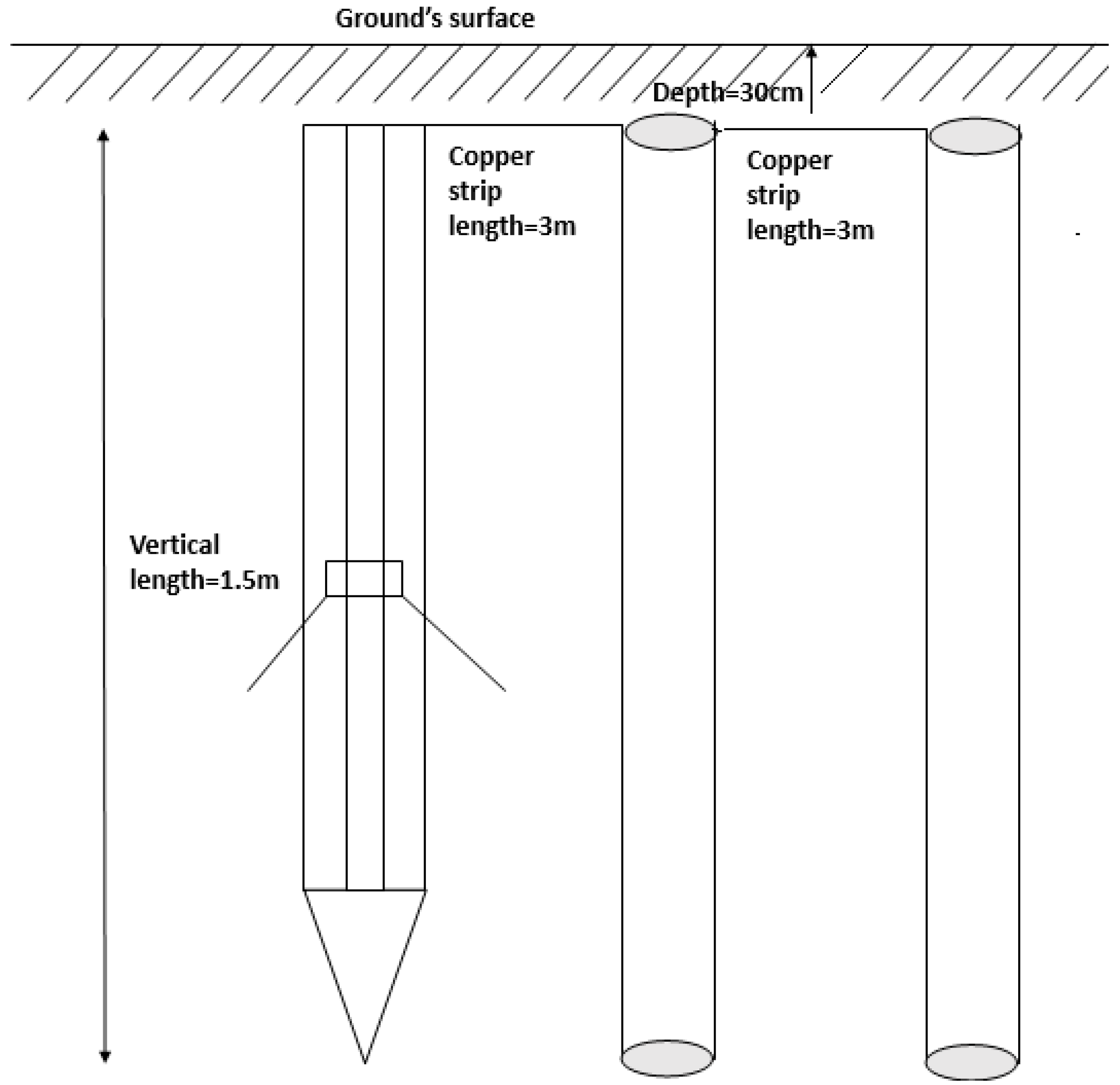
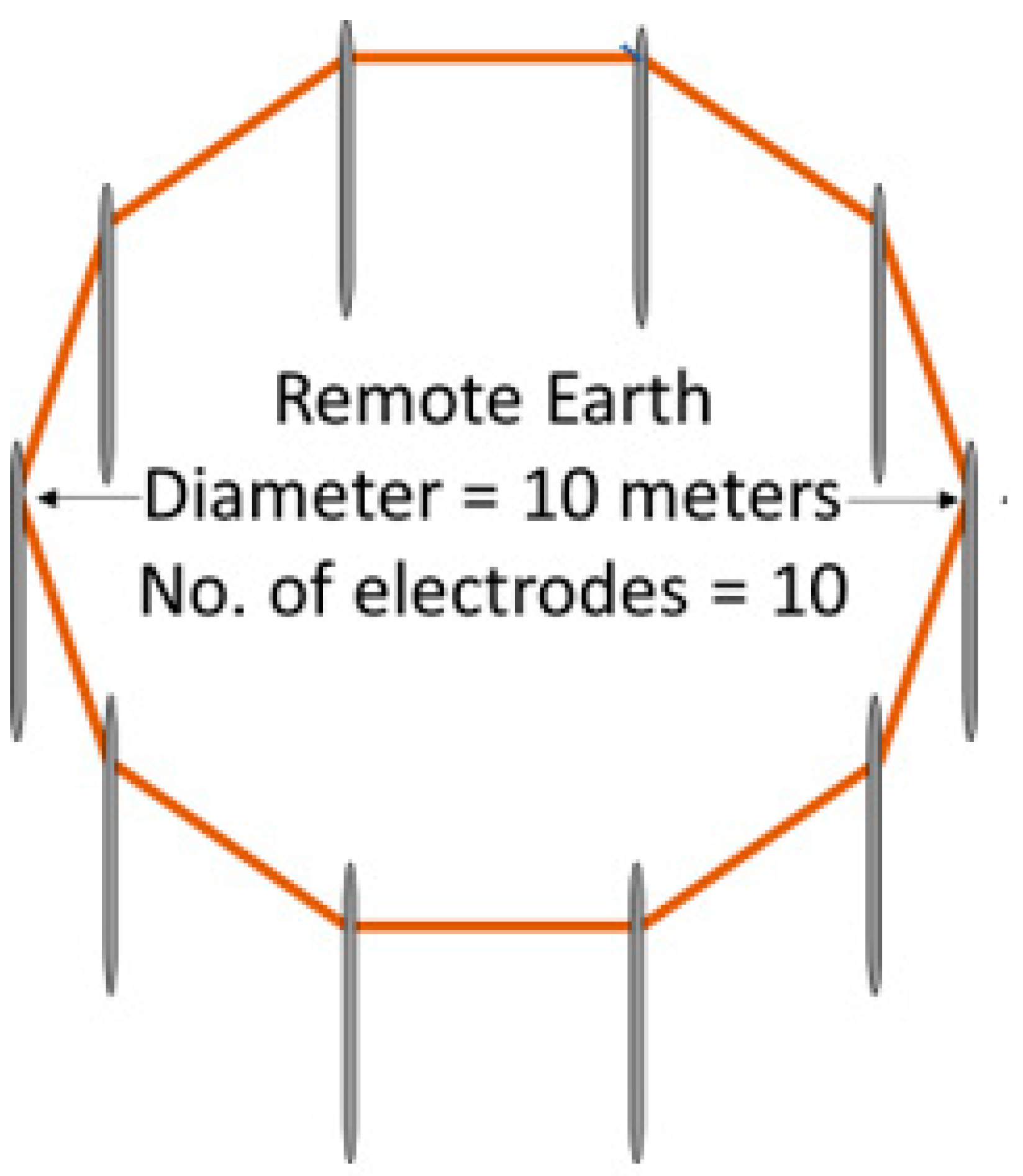
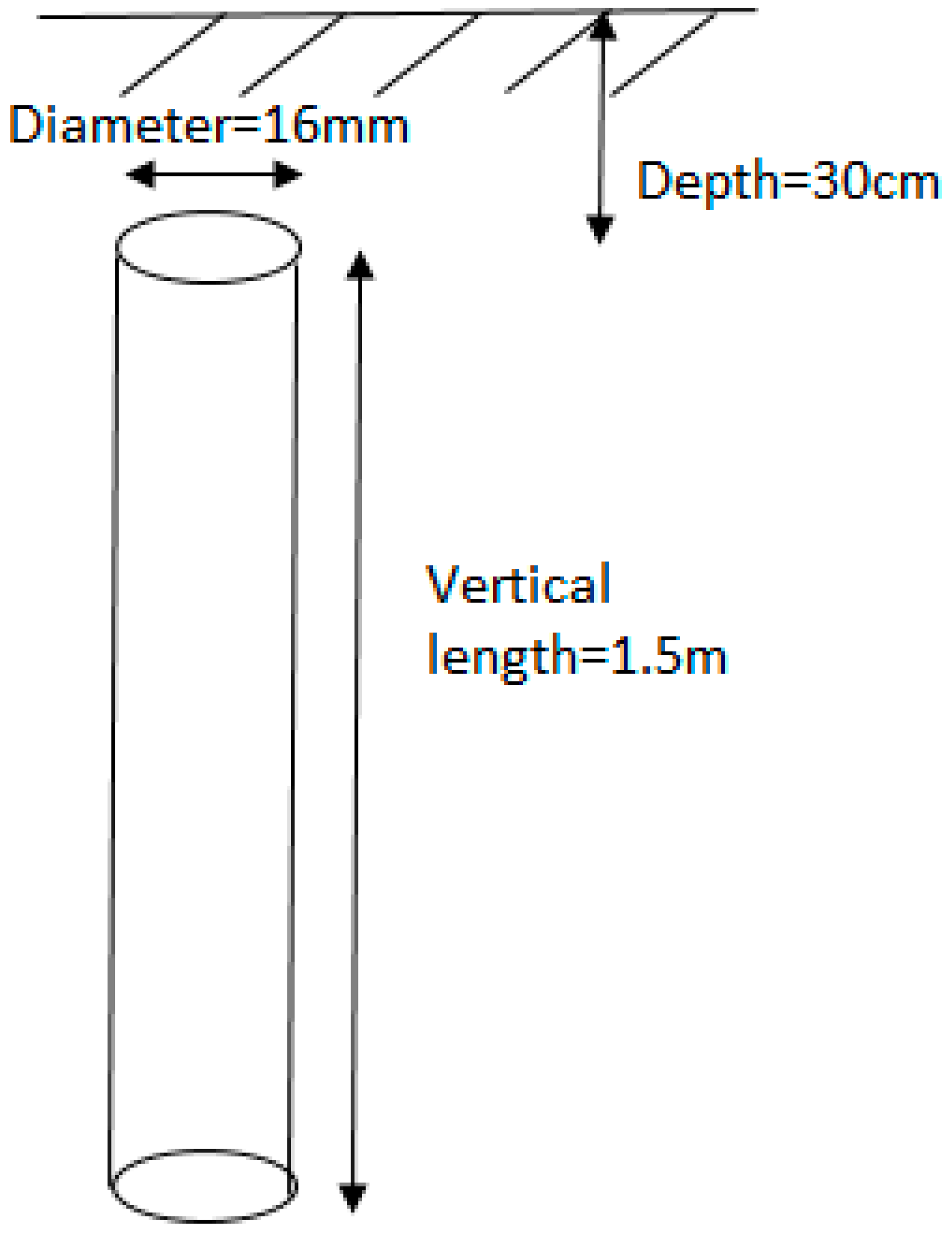
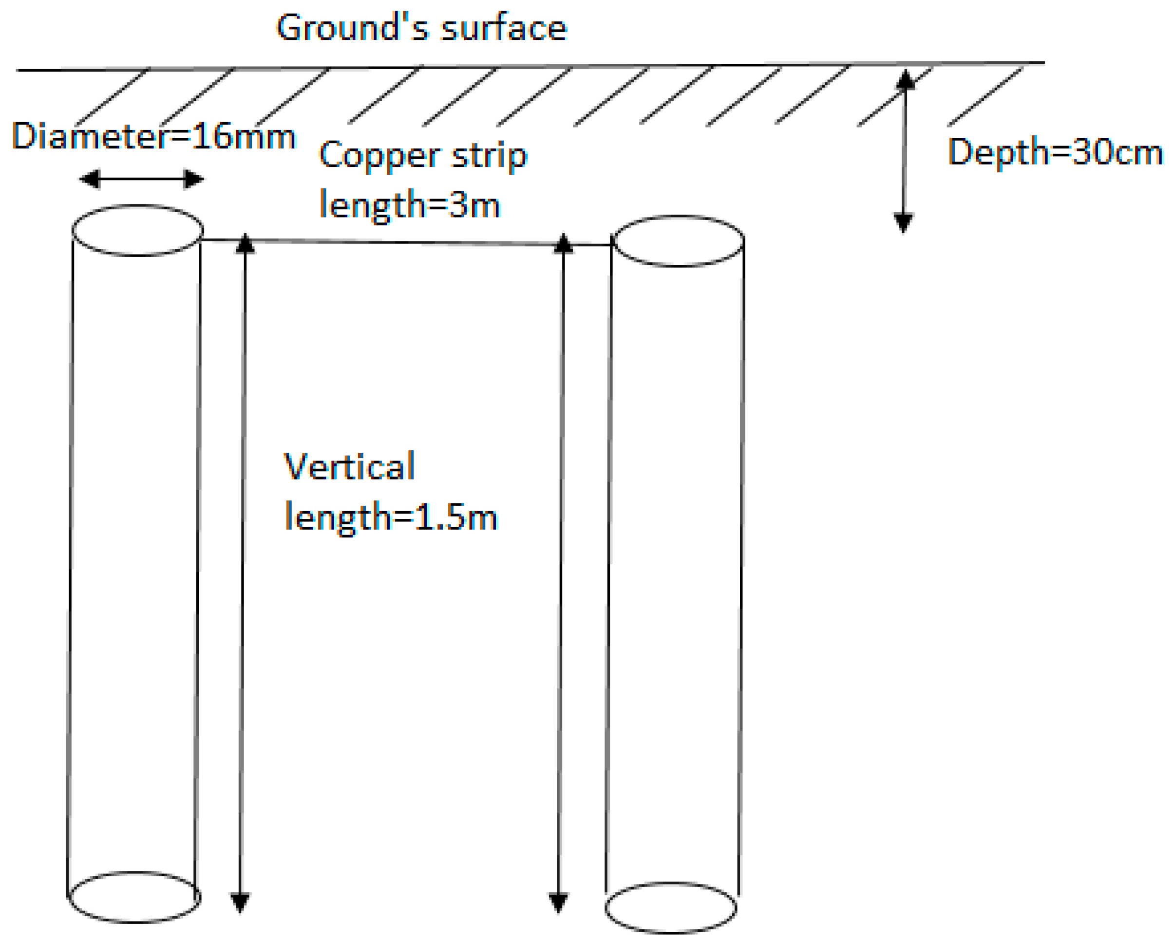
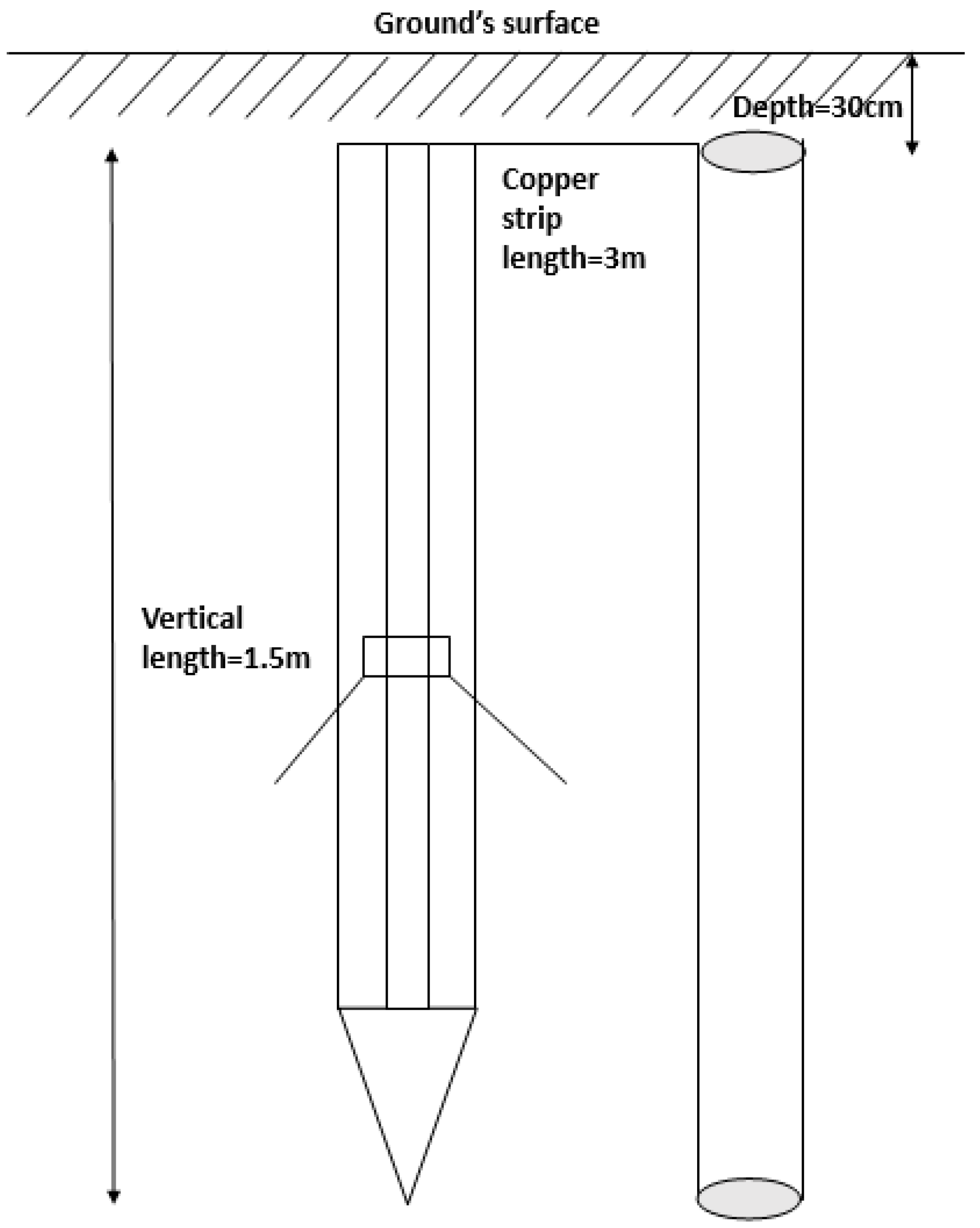
2.1. Earth Electrodes

The test area contains six configurations; a vertical single rod electrode (see Figure 1), two parallel vertical rod electrodes (see Figure 2), three parallel vertical rod electrodes (see Figure 3), a GDSR (see Figure 4), a GDSR in parallel with vertical one rod electrode (see Figure 5), a GDSR in parallel with two vertical rod electrodes (see Figure 6). Each installed vertical rod electrode is 1.5 m long and has a 16 mm diameter. The interconnections between the vertical electrodes were done with copper strips, with a width of 2.5 cm, and length of 3 m, buried to a depth of 30 cm under the ground surface. For lower current impulse tests, two new configurations were laid, where a single rod electrode was installed at 50 cm depth, and a GDSR buried to a depth of 50 cm. Very little has been mentioned in literature on the recommended spacing between the vertical rods. In [22], it is stated that ‘spacing of less than 3 m may not provide the most economical use of materials’. This shows that it is not effective to have the adjacent vertical rods too close to each other. On the other hand, [23] stated that the recommended spacing between rods should be at least 2 times the length of the rod. No specific study has focused on the effect of spacing changes on the mutual effects and performance of grounding systems. In the current study, the vertical rods were all arranged with a spacing between the rods of no less than twice the length of the electrode.
Figure 7 shows a detailed construction of a new electrode, GDSR. It comprises an outer shaft (110) and an inner shaft (120). The spike rods (123) are arranged on the body of the inner shaft (120), where the total number of spike rods is five. A pre-borehole was first made by using an auger, with a diameter of 3.8 cm. After completing the pre-borehole to a depth of at least 1.5 m, the grounding device with spike rods (100) is positioned in the hole, where the outer shaft (110) is subjected to stress and impact force while it is driven through hammering into the ground. The driving tip (122) has a pointed conical end to allow for easier penetration against obstructions encountered during driving of the rod. After that, using the provided winch (121), the inner shaft was turned in such a way that the grounding spike rods protrude out and pierce into the soil mass. GDSR was used in this study, since it was found by Petropoulos [21] that the earth electrodes attached with sharp points or needles have lower impulse resistance values than that without the sharp points. He [21] pointed out that by suitably shaping the electrodes with the sharp points, higher field intensities would be present, hence reducing the resistance values. For these reasons, a GDSR was used as part of the practical earthing systems. For checking the effectiveness of the shaping of various configurations, field measurements and testing at practical sites were carried out in this current work. A GDSR is postulated to cause and enhance ionization process in the soil, and discharge higher currents to the ground.
These eight earth electrode arrangements were used in this study for the reason that a vertical rod electrode is typically used locally, thus replicating the real conditions more closely. In order to ensure that the same test area was used, firstly, a single rod electrode was installed. Secondly, another vertical rod electrode was added, to make two parallel rod electrodes. It was then followed by the third rod electrode installed in a straight line arrangement, which gave us three parallel vertical rod electrodes. The first single rod that was installed earlier, as shown in Figure 1, was then removed, and replaced with a GDSR, giving the configuration shown in Figure 6. The third single rod electrode was then removed, whereby the configuration become as seen in Figure 5. Finally, the rod electrode was removed, thus leaving a GDSR only. For each configuration, FOP measurement and impulse tests were performed. Table 1 shows the steady-state earth resistance values, DC earth resistance value, RDC, determined with the Fall-of-Potential (FOP) method for all eight configurations. It can be seen from Table 1 that the RDC values of the earthing systems consisting of a GDSR are lower than that of conventional vertical rod electrodes. RDC for configurations 2 and 3 were found to be improved with the addition of vertical rod electrodes, with a decrease by 63% and 76.4% with the addition of one and two rod electrodes, respectively, to the single rod electrode, configuration 1. When a GDSR was used, RDC decreased by 75.5% for configuration 4 from configuration 1, 47.1% for configuration 5 from configuration 2, and 36% for configuration 6 from configuration 3. This indicates that a new electrode, the GDSR, is effective in reducing the RDC of earthing systems, which could be due the large cross sectional area of the GDSR’, as compared to conventional electrode.

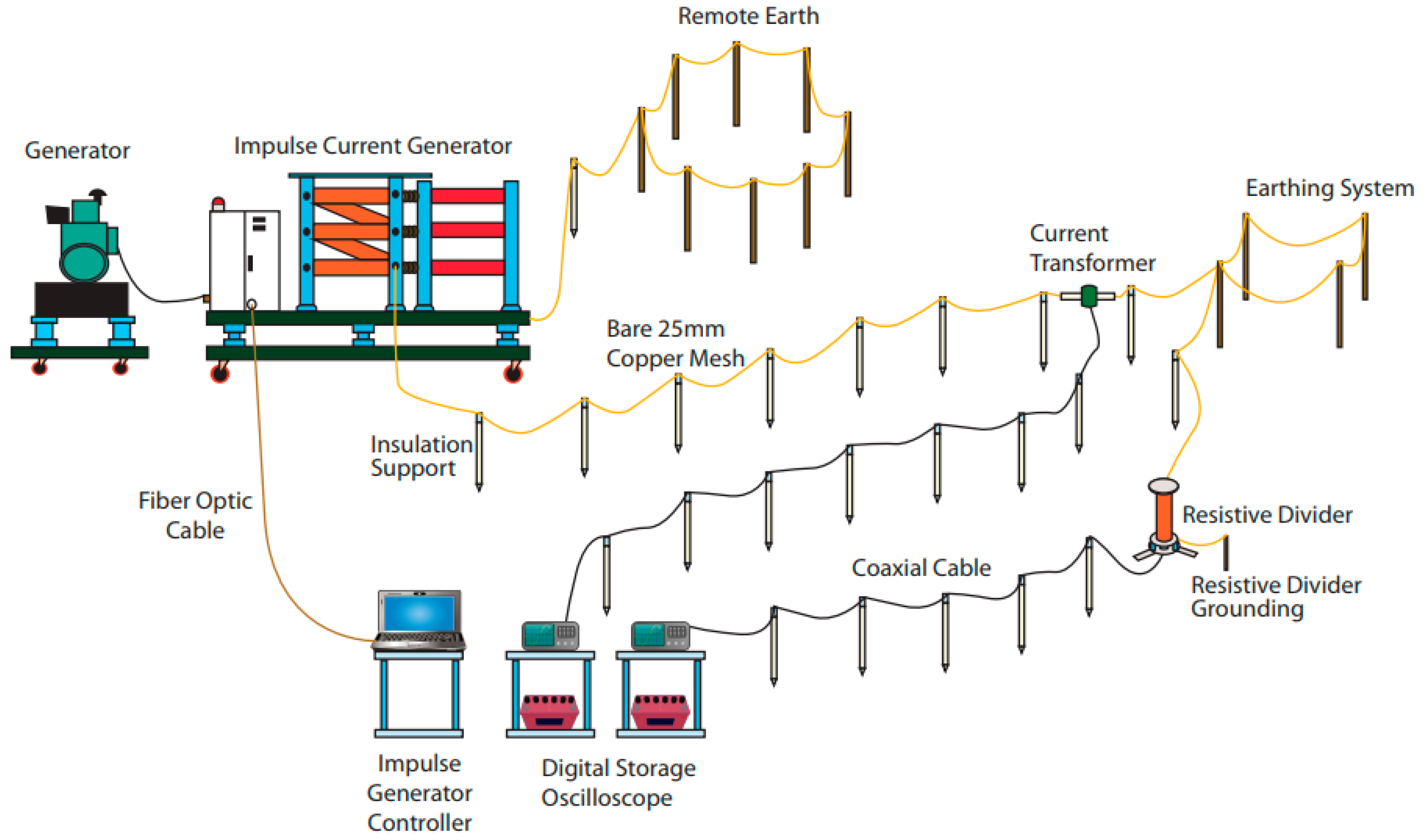
2.2. Experimental Test Set Up

Figure 8 shows the field test arrangement consisting of an impulse generator, which needs to be mounted on a lorry, insulating rods, which are made of epoxy conduits to suspend the leads/copper mesh/coaxial cables, and isolate them from earth, DC converters and batteries to provide a power source to digital storage oscilloscopes (DSOs) and a laptop, and a diesel generator to power up the impulse generator. Separate DSOs were used to capture current and voltage measurements. A resistive divider with a ratio of 3890:1 was used to capture high voltage and a current transformer with a ratio of 0.01V/A was used for current measurements.
A remote or auxillary earth is needed to provide a return path for the discharge of high impulse currents to the ground during the measurements. In this study, the remote earth consists of 10 rods in a circular ring configuration (see Figure 9). These rods, are interconnected using copper mesh, arranged on top of the rod electrodes. Using a FOP method, RDC of the remote earth was measured, and found to be 4.8 Ω. This RDC value is acceptable since it is lower than that RDC of grounding systems under tests (see Table 1).

3. Results and Analysis

This present work aims to quantify the effectiveness of a GDSR with other practical grounding systems under high magnitude impulse currents, above 5 kA, under both impulse polarities. The RDC values of grounding systems have been presented in Section 2. This allows comparison with the performance of grounding systems under high-magnitude impulse currents.

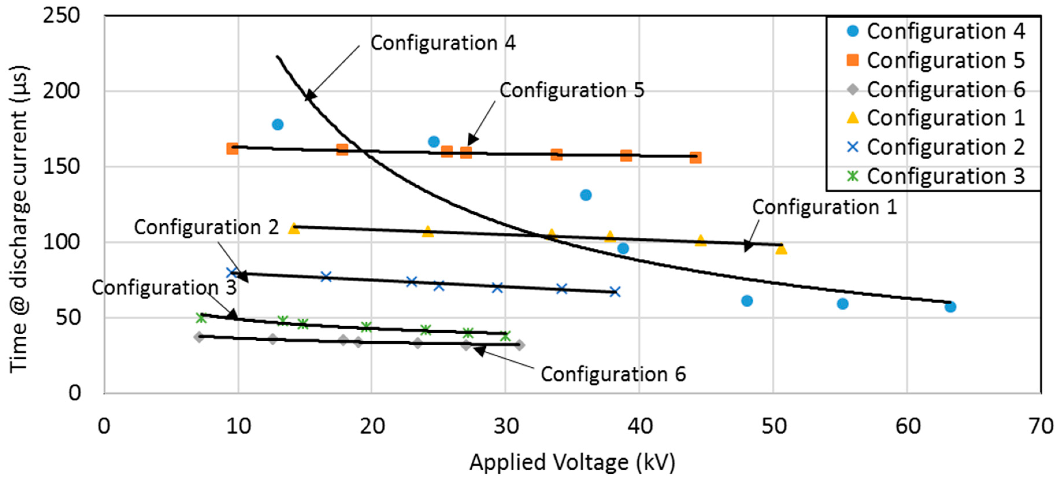
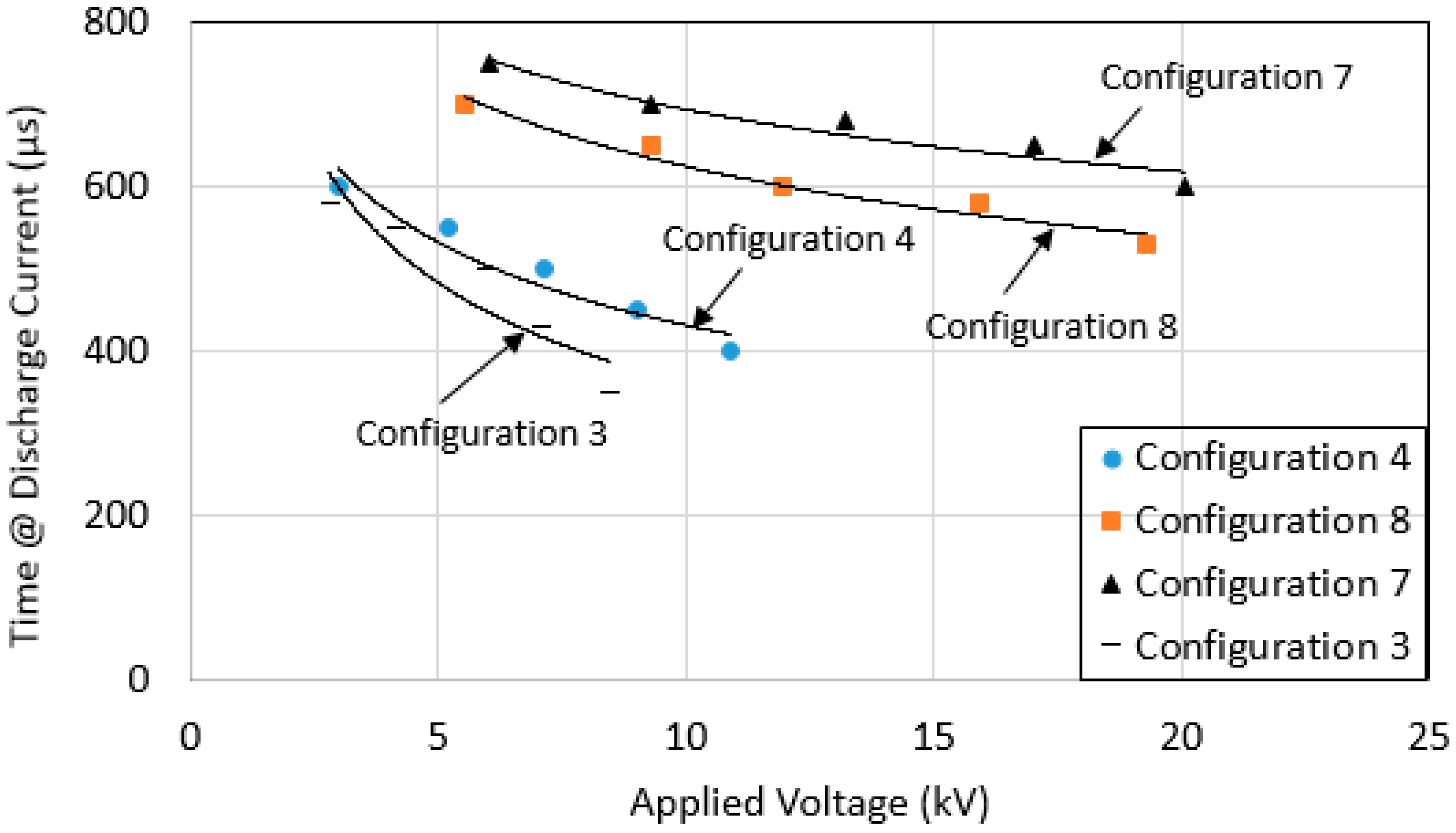
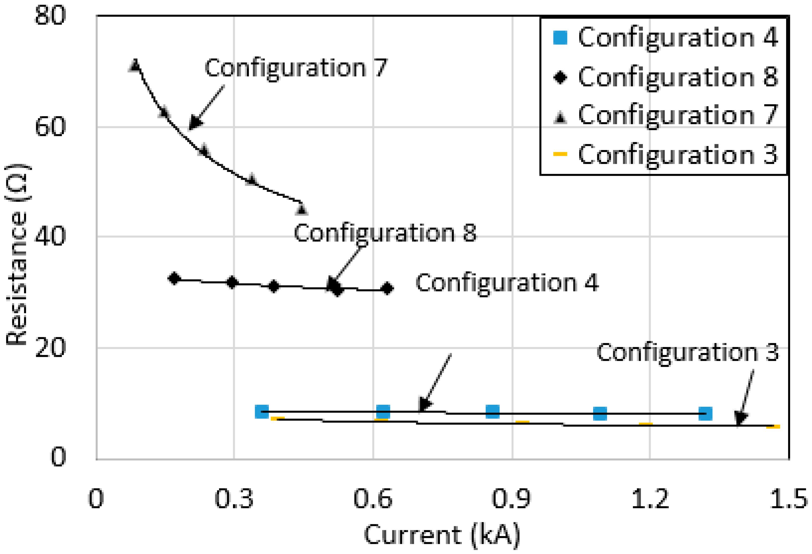
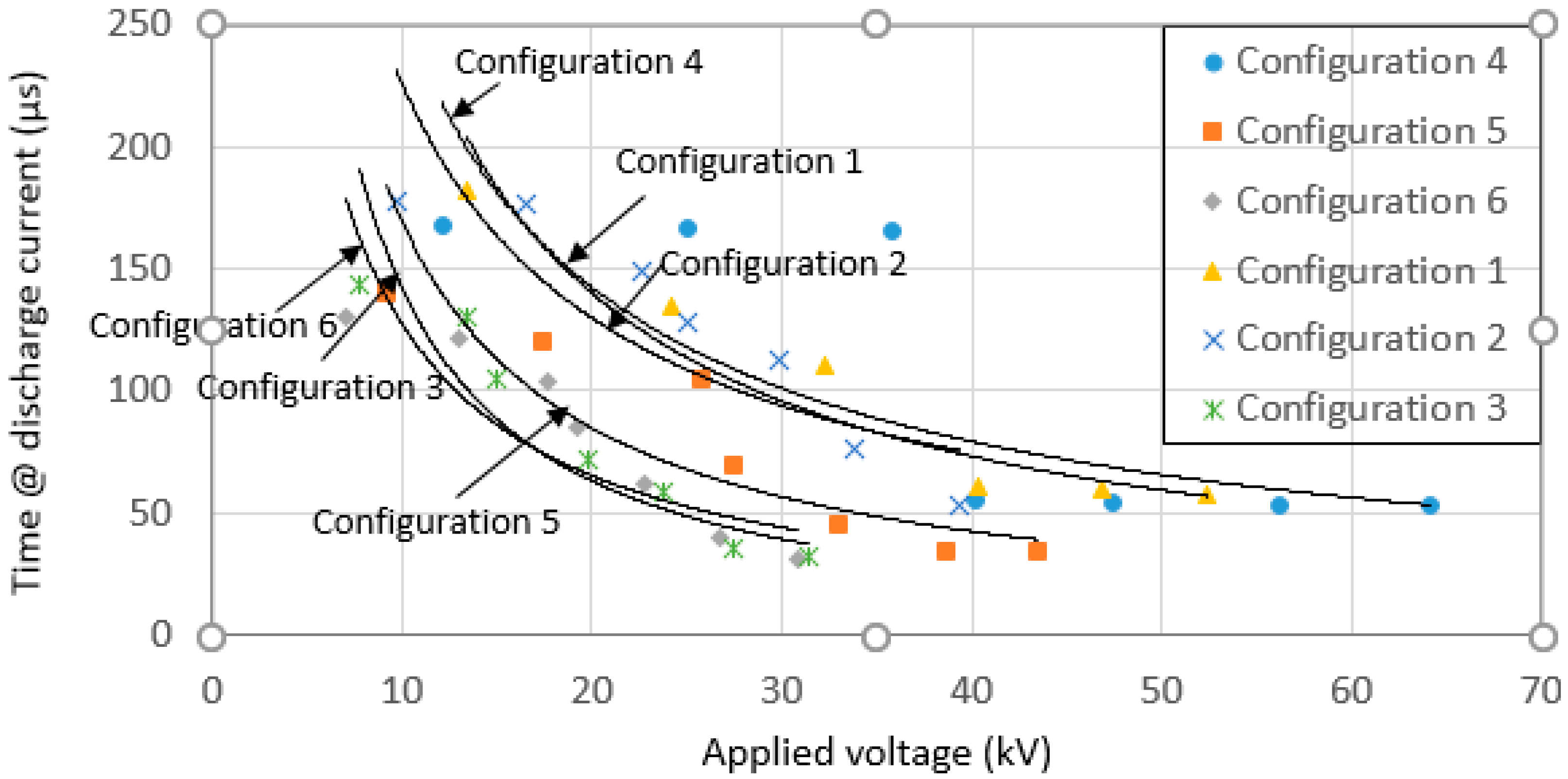
3.1. Effect of Earth Electrode’s Configurations

Figure 10 and Figure 11 show selected typical voltage and current traces for configuration 2 at charging voltages of 150 kV and 350 kV, respectively. The voltage and current traces of other configurations and voltage magnitudes were similar to those presented in Figure 10 and Figure 11. In this work, the time to discharge to zero for current trace was measured. This parameter may provide information related to the effectiveness of the grounding systems in discharging a high current into the ground, where the faster the time taken to discharge for current trace, the better the grounding system is.
Figure 12 shows the measured time to discharge to zero for current trace at different applied voltage. For all configurations, (except for configuration 4), the time for current trace to discharge to zero were found to be independent of applied voltage. Configurations 3 and 6, with large sized grounding systems were found to have a faster time for the current trace to discharge to zero, which shows the good conductivity of the grounding systems. Generally, it is understood that the larger the size of a grounding system, the less time taken for current to discharge to zero, due to the fact more paths are available for the current to disperse. Some discrepancies in the results were also seen, where the time taken for current trace to discharge to zero for configuration 5 is higher than that configuration 1 and 2, despite the fact configuration 5 has a larger sized grounding system. This could be due to uncontrollable thermal and ionization processes in the soil, which have been highlighted in previously published work [1,2,3,19,20]. Another possibility is that this is also due to the inductive component, which can be significant under transient conditions. However, it is out of the scope of the current paper to come up with the equivalent circuit, and show evidence of an inductive effect for each configuration.
In this study, the impulse resistance, Rimpulse, was determined as the ratio of voltage at the peak current to the corresponding peak current. Figure 13 shows the measured Rimpulse for various grounding systems under high impulse currents, up to 16 kA. As can be seen, there is little dependence of Rimpulse on the current magnitudes (except for configuration 1). Configuration 1 had the highest RDC, and thus expectedly showed the highest reduction, as claimed in many prior publications [2,3,4,5,6,7,8,9,10,18,19,20,21] where the higher the DC earth resistance, the higher the current-dependent characteristics of earth resistance during the passage of high currents.
It was also noted that some differences in the Rimpulse with the current peak can be seen with the addition of GDSR at low current magnitudes, below 3 kA. However, at higher current magnitudes, little observable effect can be seen on Rimpulse. This could be due to a full development of an ionization zone at high current, thus the performance of grounding systems has become independent of the grounding electrodes and current magnitudes.

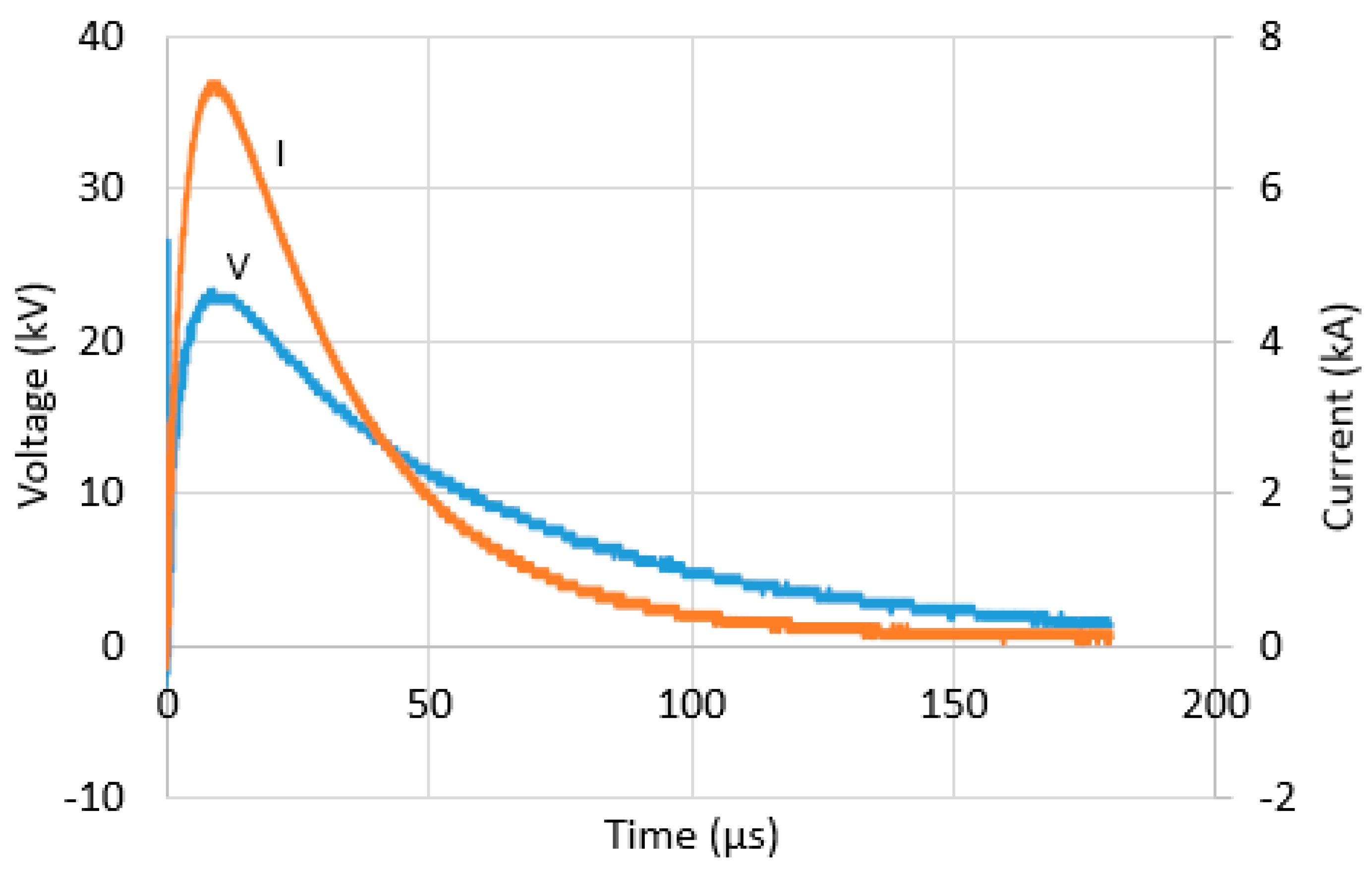
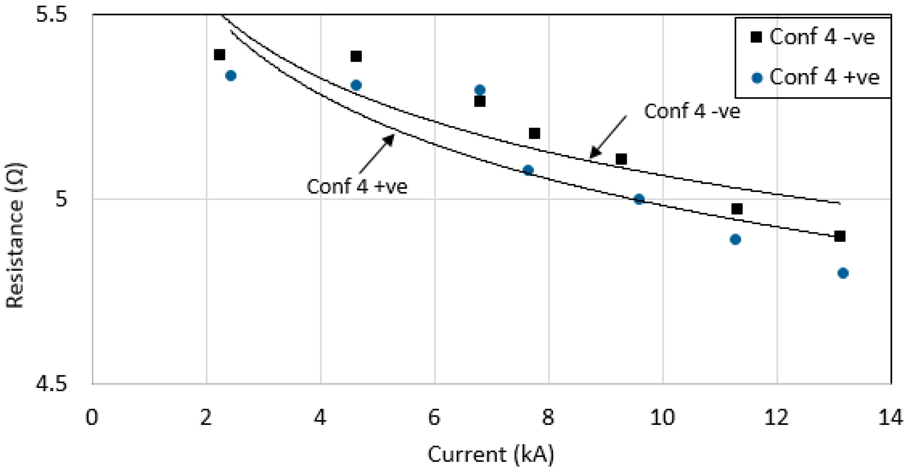
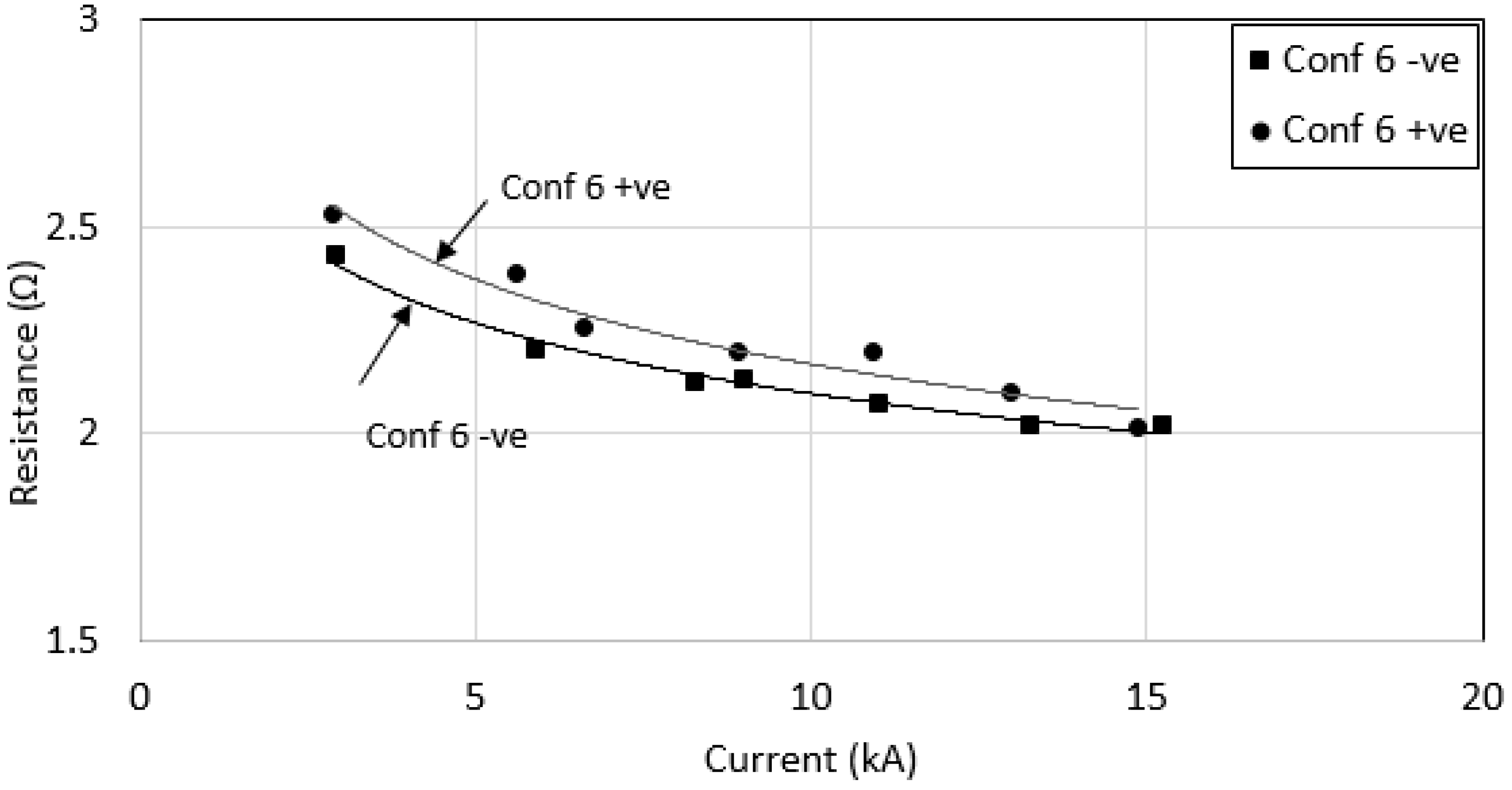
3.2. Effect of Low Current Magnitudes

Due to current independence of earth resistance at high current magnitudes, as presented in Section A, experiments using a smaller impulse generator, which can generate up to 50 kV, 2 kA currents were performed to further investigate the grounding characteristics under lower current magnitude conditions. Impulse tests were conducted on four configurations; configurations 3 and 4, and another two new configurations, labelled as configurations 7 and 8. Configuration 7 is similar to configuration 1, but buried at 50 cm, and configuration 8 is similar to configuration 4, buried at 50 cm in the soil. Lesser depth, of 50 cm below the ground’s surface, was used to obtain high resistances, hence low current magnitudes, for the vertical electrodes. RDC values were measured for both configurations 7 and 8, and found to be 313.2 Ω and 85.2 Ω, respectively. Using a similar test set up, remote earth and transducers as presented in Section 2.2, impulse tests were conducted on the four configurations using smaller impulse generator. Figure 14 shows voltage and current impulse shapes of configuration 7 at a charging voltage of 25 kV. Similar voltage and current traces were seen at different voltage magnitudes for configurations 7 and 8. However, faster voltage and current discharge times were seen for configuration 3 and 4, at various voltage magnitudes (see Figure 15), due to their low RDC, which thus provides better conduction of the grounding systems. When time to discharge to zero for current trace versus applied voltage was plotted for all four configurations under lower voltage magnitudes (Figure 16), it was noted that a reduction in time to discharge to zero for current traces with increasing applied voltage. This trend was not clearly observable at higher current magnitudes, presented earlier in Figure 12. A graph of Rimpulse was plotted for increasing current magnitudes (see Figure 17) for all four configurations. It can be seen that Rimpulse is decreasing significantly with current magnitude for configuration 7, with the highest RDC, 313.2 Ω. However, Rimpulse was found to be less current dependent for grounding systems with lower RDC, below 85 Ω.

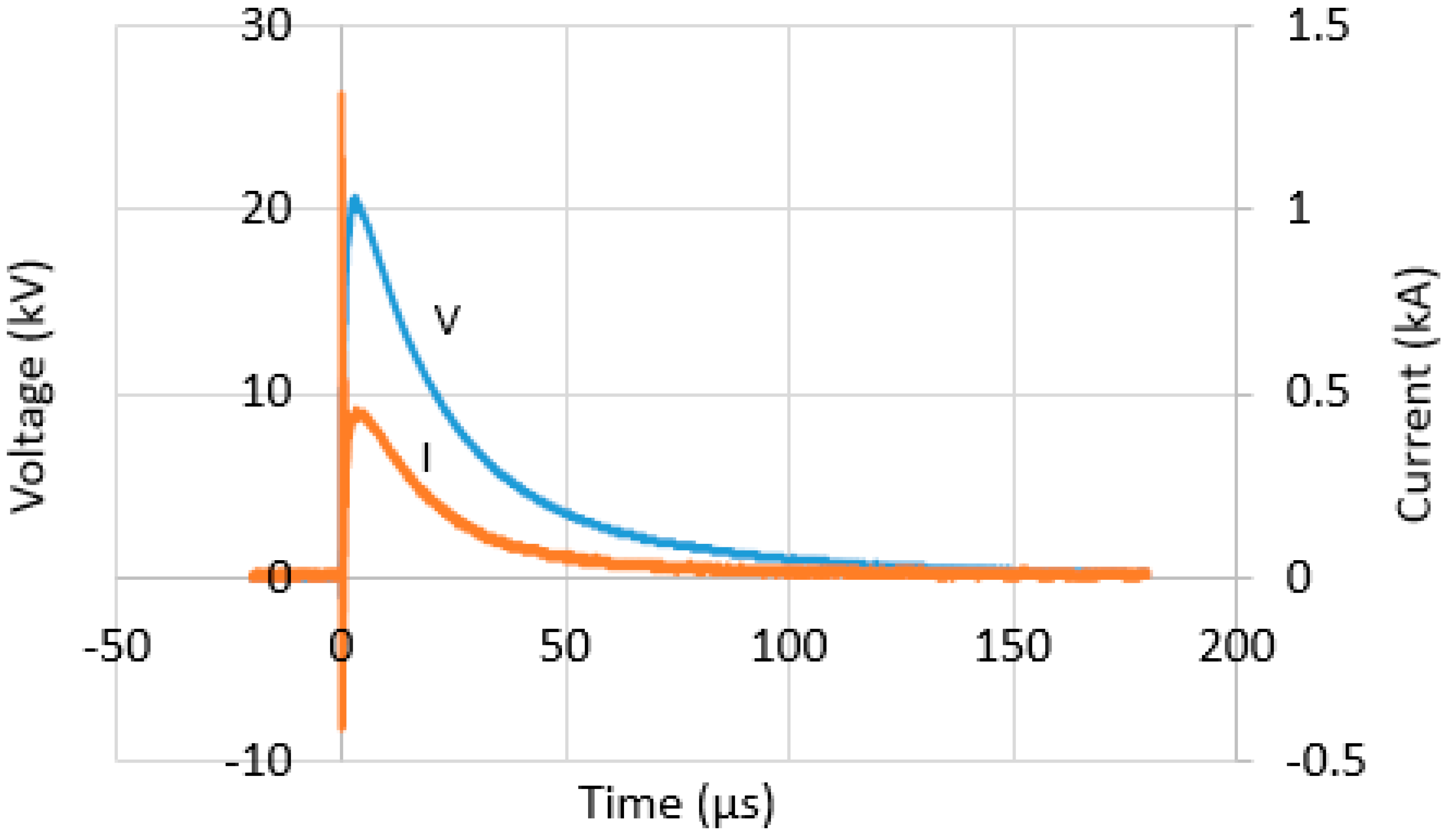
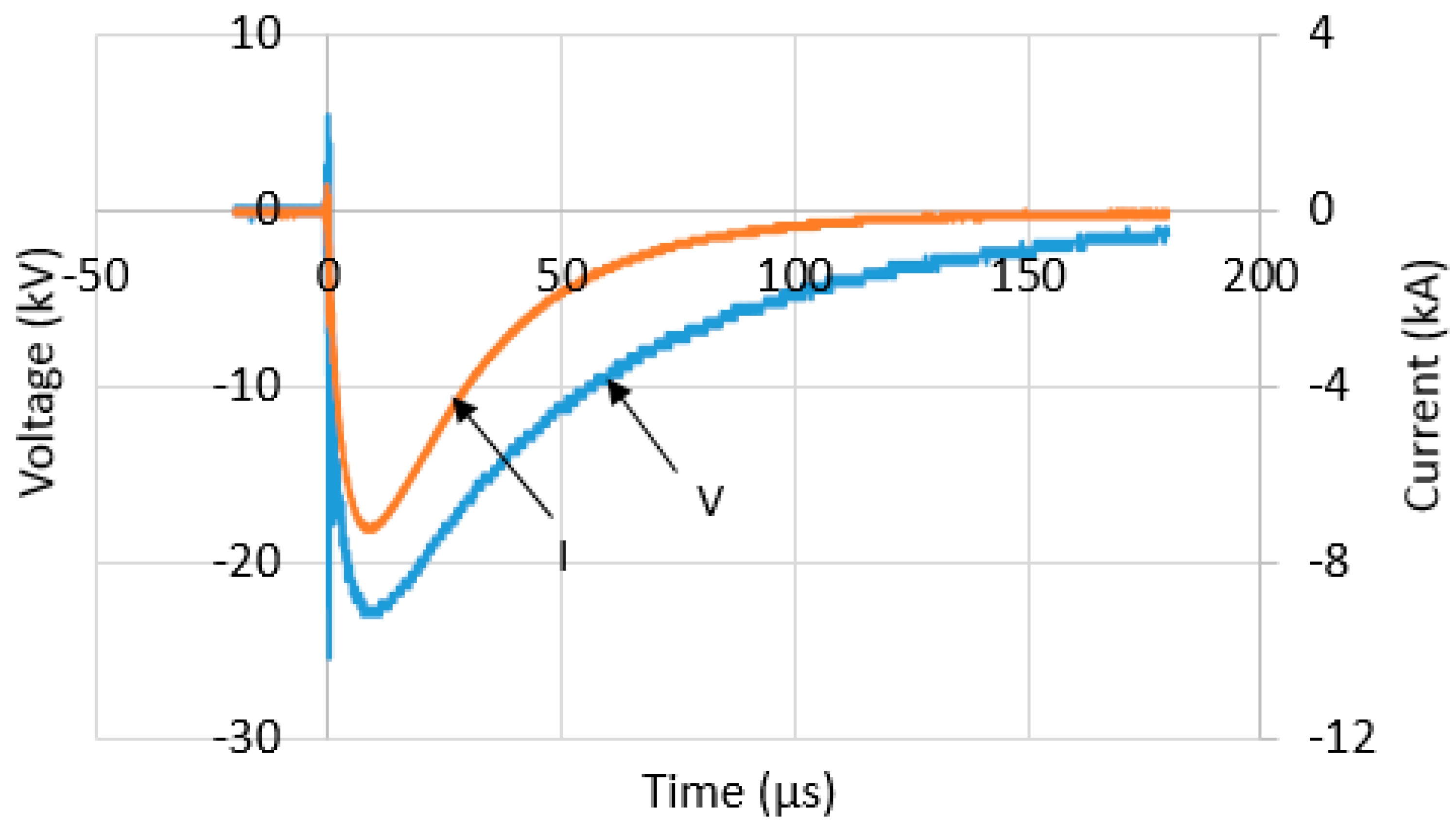
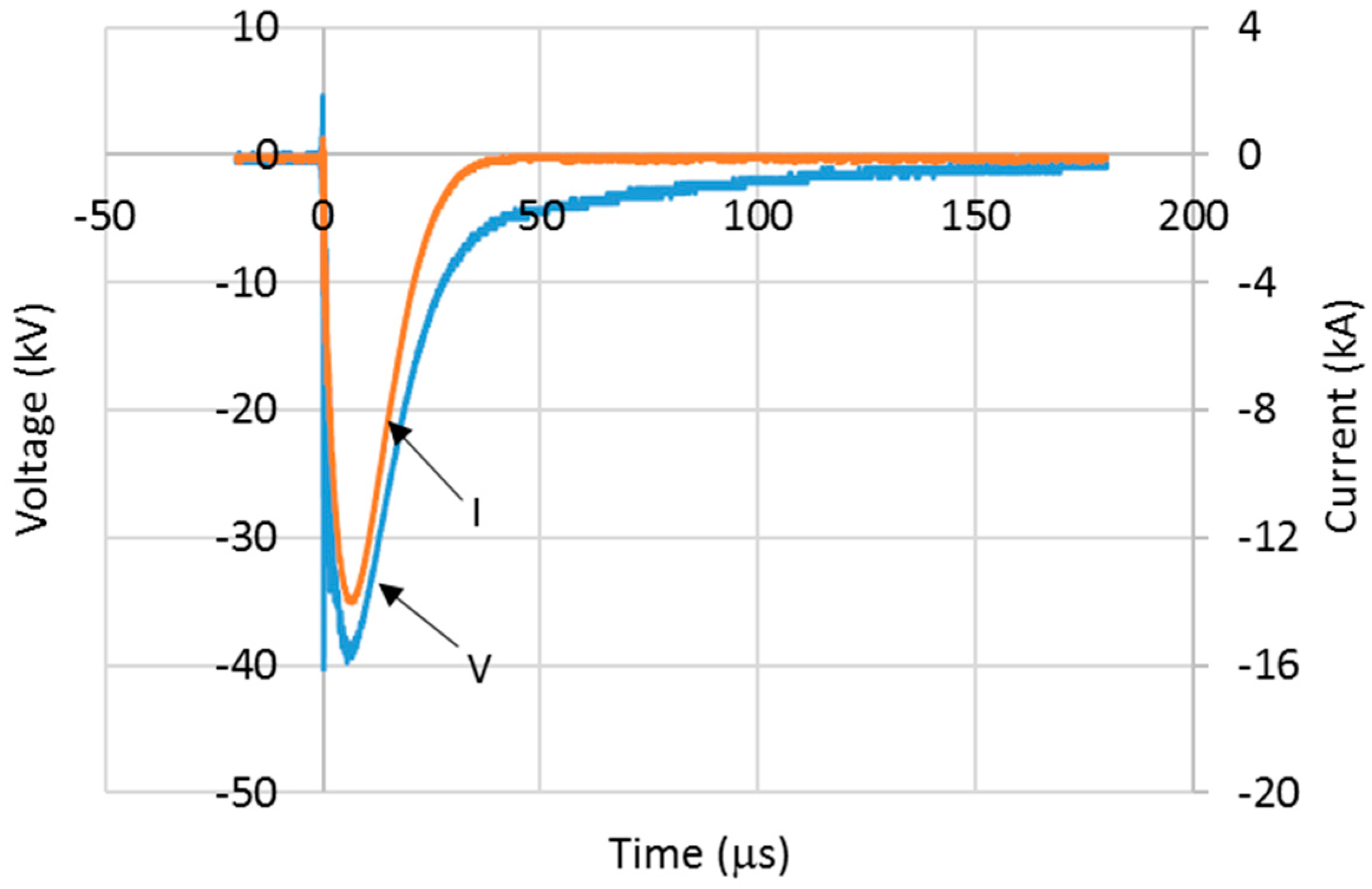
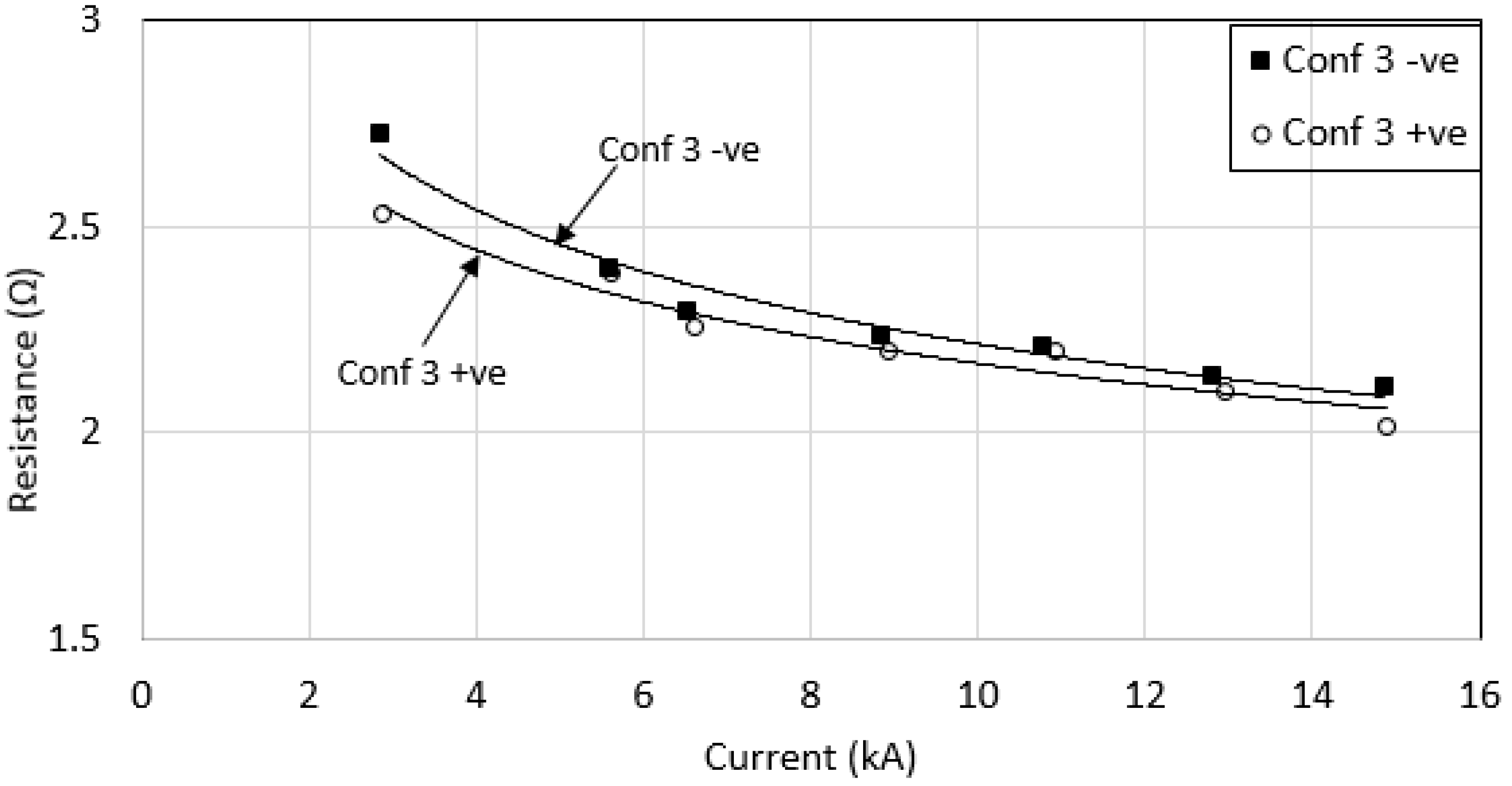
3.3. Effect of Impulse Polarity

In a previously published work [18], it was noted that an effect of impulse polarity was seen in high resistivity soil. In this work, a low soil resistivity profile was used. Figure 18 and Figure 19 show typical voltage and current traces for configuration 2 at charging voltages of 150 kV and 350 kV, respectively. Similar voltage and current traces were observed for various configurations and voltage magnitudes. As the voltage magnitudes were increased, a significant reduction in the time for current trace to discharge to zero was observed for all configurations of grounding systems (see Figure 20). This trend is found to be different than that observed for positive polarity (shown in Figure 12), where only configuration 4 has the reduction of time for current trace to discharge to zero when under positive impulse polarity. A faster time for current to discharge to zero for large sized grounding systems (configurations 3, 5 and 6) under negative impulse polarity was also noted. This could be influenced by the lower RDC in large grounding systems, thus discharging current at a faster time than that in smaller size of grounding systems. It was also noted that the trend of time taken for current trace to discharge to zero under negative polarity is more consistent, and similar to that found in other publications [19,20], than that found under positive impulse polarity. However, the inconsistent results for the time taken for current to discharge to zero under positive polarity are still not well understood.
When the voltage magnitudes under negative impulse polarity were increased, the Rimpulse was found to have small reduction with increasing current (see Figure 21). Configurations 3 and 6, with larger sized grounding systems were found to have the lowest Rimpulse, which is a similar trend to that obtained under positive impulse polarity. These measured Rimpulse values with increasing currents were also plotted together under both impulse polarities for each configuration (see Figure 22, Figure 23, Figure 24, Figure 25, Figure 26 and Figure 27). As can be seen, for configurations 1, 2, 3 and 4, a higher Rimpulse was recorded with negative impulses compared with positive impulses, as shown in Figure 22, Figure 23, Figure 24 and Figure 25, respectively. A similar trend was seen in [20,21] whom conducted laboratory tests where Rimpulse values were found to be higher for negative impulses than for positive impulses. As generally known, a decrease in Rimpulse with increasing voltage indicates the ionization process in soil, which was thought to occur in the air voids within the soil [1,2,3,19,20]. Since it is expected that the discharges in air would require higher level voltages, and less currents for negative impulses compared to positive impulses, higher Rimpulse in negative impulses than positive impulses would occur. When Reffin et al. [18] performed experiments using field measurements on practical grounding systems installed in various soil conditions, they found that higher Rimpulse with negative impulses than that positive impulses for grounding systems with high RDC (62.6 Ω). On the other hand, Rimpulse was found to be independent of impulse polarity for low RDC (4.7 Ω). In this work, the electrodes were installed at the same site, with the same soil resistivity profile. The highest RDC values are for configurations 1, 2, 3 and 4, and these configurations were found to have higher Rimpulse under negative impulses than under positive impulses. On the other hand, for lower RDC (configurations 5 and 6), the results were found to be inconsistent, where Rimpulse were found to be independent of impulse polarities for configuration 5, and Rimpulse were found higher under positive impulses than that negative impulses, as shown in Figure 26 and Figure 27 for configurations 5 and 6, respectively.

4. Conclusions

Experiments were performed on different grounding configurations using various configurations at installed in low resistivity profile soils at the same field site. It was found that under high impulse currents, more than 5 kA, less current dependence of Rimpulse was observed. The characteristics of various configurations were also investigated under lower current magnitudes, below 2 kA. High nonlinearity was observed for grounding systems with high RDC (above 313.2 Ω). The results revealed that the new GDSR earth electrode is more suitable to be used for low fault currents, such as 11 kV systems and below. When the grounding systems of various configurations were tested under negative impulse polarity, higher Rimpulse was seen in negative impulses than positive impulses for grounding systems with high RDC. This study also shows that under positive polarity conditions, only configuration 4 has a dependence on the time to discharge to zero for current trace, whereas a dependence of time to discharge to zero for current trace is not seen in the other configurations. On the other hand, for negative polarity, the measured time to discharge to zero for current traces decreases with applied voltage for all configurations, and the results are more consistent than for positive impulse polarities.

Author Contributions

A.W.A.A., M.S.R., N.M.N., and S.A.S.A. involved in setting up the experiment, A.W.A.A. and M.S.R. sorted out the data, A.W.A.A. prepared the draft and N.M.N. helped with validation of analysis. N.N.A. helped with the draft revision, N.N.A., N.M.N. secured the funding.

Funding

This research was funded by Telekom Malaysia Research and Development (TMR&D), grant number MMUE180008, MMUE170005 and MMUE180027.

Conflicts of Interest

The authors declare no conflict of interest.

References

  1. Towne, H.M. Impulse characteristics of driven grounds. Gen. Electr. Rev. 1928, 31, 605–609. [Google Scholar]
  2. Bellaschi, P.L. Impulse and 60-cycle characteristics of driven grounds. Electr. Eng. 1941, 60, 123–127. [Google Scholar] [CrossRef]
  3. Bellaschi, P.L.; Armington, R.E.; Snowden, A.E. Impulse and 60-Cycle Characteristics of Driven Grounds-II. Electr. Eng. 1942, 61, 349–363. [Google Scholar] [CrossRef]
  4. Sonoda, T.; Takesue, H.; Sekioka, S. Measurement on Surge Characteristics of Grounding Resistance of Counterpoises for Impulse Currents. In Proceedings of the 25th International Conference on Lightning Protection, Rhodes, Greece, 18–22 September 2000; pp. 411–415. [Google Scholar]
  5. Sekioka, S.; Hayashida, H.; Hara, T.; Ametani, A. Measurement of Grounding Resistance for High Impulse Currents. IEE Proc. Gener. Transm. Distrib. 1998, 145, 693–699. [Google Scholar] [CrossRef]
  6. Takeuchi, M.; Yasuda, Y.; Fukuzono, H. Impulse Characteristics of a 500 kV Transmission Tower Footing Base with Various Grounding Electrodes. In Proceedings of the 24th International Conference on Lightning Protection, Birmingham, UK, 14–18 September 1998; pp. 513–517. [Google Scholar]
  7. Yunus, M.; Nor, N.M.; Agbor, N.; Abdullah, S.; Ramar, K. Performance of Earthing systems for Different Earth Electrode Configurations. IEEE Trans. Ind. Appl. 2015, 51, 5335–5342. [Google Scholar] [CrossRef]
  8. Haddad, A.; Griffiths, H.; Ahmeda, M.; Harid, N. Experimental Investigation of the Impulse Characteristics of Practical Ground Electrode Systems. In Proceedings of the International Conference on High Voltage Engineering and Application, New Orleans, MS, USA, 11–14 October 2010. [Google Scholar]
  9. Yang, S.; Zhou, W.; Huang, J.; Yu, J. Investigation on Impulse Characteristic of Full-Scale Grounding Grid in Substation. IEEE Trans. Electromagn. Compat. 2018, 60, 1993–2001. [Google Scholar] [CrossRef]
  10. Harid, N.; Griffiths, H.; Haddad, A. Effect of Ground Return Path on Impulse Characteristics of Earth Electrodes. In Proceedings of the 7th Asia-Pacific International Conference on Lightning, Chengdu, China, 1–4 November 2011; pp. 686–689. [Google Scholar]
  11. Guo, D.; Clark, D.; Lathi, D.; Harid, N.; Griffiths, H.; Ainsley, A.; Haddad, A. Controlled Large-Scale Tests of Practical Grounding Electrodes—Part I: Test Facility and Measurement of Site Parameters. IEEE Trans. Power Deliv. 2014, 29, 1231–1239. [Google Scholar] [CrossRef]
  12. Mousa, S.; Harid, N.; Griffiths, H.; Haddad, A. Experimental Investigation on High-Frequency and Transient Performance of a Vertical Earth Electrode. In Proceedings of the Universities Power Engineering Conference (UPEC), Soest, Germany, 5–8 September 2011; pp. 1–4. [Google Scholar]
  13. Clark, D.; Guo, D.; Lathi, D.; Harid, N.; Griffiths, H.; Ainsley, A.; Haddad, A. Controlled Large-Scale Tests of Practical Grounding Electrodes—Part II: Comparison of Analytical and Numerical Predictions with Experimental Results. IEEE Trans. Power Deliv. 2014, 29, 1240–1248. [Google Scholar] [CrossRef]
  14. Guo, D.; Lathi, D.; Harid, N.; Griffiths, H.; Haddad, A.; Ainsley, A. Large-Scale Earthing Test Facilities at Dinorwig Power Station. In Proceedings of the International Conference on Conduction Monitoring and Diagnosis, Beijing, China, 21–24 April 2008; pp. 808–811. [Google Scholar]
  15. Duan, L.; Zhang, B.; He, J.; Xiao, L.; Qian, L. Experimental Study on Transient Characteristics of Grounding Grid for Substation. In Proceedings of the 25th International Conference of Lightning Protection (ICLP), Estoril, Portugal, 25–30 September 2016. [Google Scholar]
  16. Etobi, N.; Nor, N.M.; Abdullah, S.; Othman, M. Characterizations of a Single Rod Electrode under High Impulse Currents with Different Polarities. In Proceedings of the 1st IEEE International Conference on Electrical Materials and Power Equipment (ICEMPE), Xi’an, China, 14–17 May 2017. [Google Scholar]
  17. Abdullah, S.; Nor, N.M.; Ramar, K. Field measurements on Earthing Systems of Different Soil Resistivity Values under High Impulse Conditions. Electr. Eng. 2017, 99, 1005–1011. [Google Scholar] [CrossRef]
  18. Reffin, M.; Nor, N.; Ahmad, N.; Abdullah, S. Performance of Practical Grounding Systems under High Impulse Conditions. Energies 2018, 11, 3187. [Google Scholar] [CrossRef]
  19. Nor, N.M.; Haddad, A.; Griffiths, H. Factors Affecting Soil Characteristics under Fast Transients. In Proceedings of the International Conference of Power Systems Transients (IPST), New Orleans, MS, USA, 14 August 2003. [Google Scholar]
  20. Nor, N.M.; Haddad, A.; Griffiths, H. Characterization of Ionization Phenomena in Soils under fast impulses. IEEE Trans. Power Deliv. 2006, 21, 353–361. [Google Scholar] [CrossRef]
  21. Petropoulos, G.M. The High-Voltage Characteristics of Earth Resistances. J. Inst. Electr. Eng. Part II Power Eng. 1948, 95, 59–70. [Google Scholar]
  22. IEEE Standard 142: IEEE Recommended Practice for Grounding of Industrial and Commercial Power Systems; Institute of Electrical and Electronics Engineers: Piscataway, NJ, USA, 2007.
  23. Simmons, P. Electrical Grounding and Bonding, Based on 2017 National Electricity Code (NEC), 5th ed.; CENGAGE Learning: Boston, MA, USA, 2012. [Google Scholar]
Figure 1. Configuration 1 with a single vertical rod electrode.
Energies 12 01138 g001
Figure 2. Configuration 2 with two parallel vertical rod electrodes.
Energies 12 01138 g002
Figure 3. Configuration 3 with three parallel vertical rod electrodes.
Energies 12 01138 g003
Figure 4. Configuration 4, a grounding device with spike rods.
Energies 12 01138 g004
Figure 5. Configuration 5, a grounding device with spike rods and a vertical rod electrode.
Energies 12 01138 g005
Figure 6. Configuration 6, a grounding device with spike rods and 2 vertical rod electrodes.
Energies 12 01138 g006
Figure 7. Construction of a grounding device with spike rods.
Energies 12 01138 g007
Figure 8. Test arrangement for field tests on practical grounding systems.
Energies 12 01138 g008
Figure 9. Remote earth for tests on various grounding systems.
Energies 12 01138 g009
Figure 10. Voltage and current traces for configuration 2 at charging voltage of 150 kV under positive polarity.
Energies 12 01138 g010
Figure 11. Voltage and current traces for configuration 2 at a charging voltage of 350 kV under positive polarity.
Energies 12 01138 g011
Figure 12. Time taken for current trace to discharge to zero vs. applied voltage for various grounding systems under positive impulse polarity.
Energies 12 01138 g012
Figure 13. Rimpulse vs. peak current for various grounding systems under positive impulse polarity.
Energies 12 01138 g013
Figure 14. Voltage and current traces for configuration 7 at charging voltage of 25 kV under positive polarity.
Energies 12 01138 g014
Figure 15. Voltage and current traces for configuration 8 at charging voltage of 25 kV under positive polarity.
Energies 12 01138 g015
Figure 16. Time taken for current trace to discharge to zero vs. applied voltage for various grounding systems under low voltage magnitudes.
Energies 12 01138 g016
Figure 17. Rimpulse vs. peak current for various grounding systems under low voltage magnitudes.
Energies 12 01138 g017
Figure 18. Voltage and current traces for configuration 2 at charging voltage of 150 kV under negative polarity.
Energies 12 01138 g018
Figure 19. Voltage and current traces for configuration 2 at charging voltage of 350 kV under negative polarity.
Energies 12 01138 g019
Figure 20. Time taken for current trace to discharge to zero vs. applied voltage for various grounding systems under negative impulse polarity.
Energies 12 01138 g020
Figure 21. Rimpulse vs. peak current for various grounding systems under negative impulse polarity.
Energies 12 01138 g021
Figure 22. Impulse resistances versus current peak for configuration 1.
Energies 12 01138 g022
Figure 23. Impulse resistances versus current peak for configuration 2.
Energies 12 01138 g023
Figure 24. Impulse resistances versus current peak for configuration 3.
Energies 12 01138 g024
Figure 25. Impulse resistances versus current peak for configuration 4.
Energies 12 01138 g025
Figure 26. Impulse resistances versus current peak for configuration 5.
Energies 12 01138 g026
Figure 27. Impulse resistances versus current peak for configuration 6.
Energies 12 01138 g027
Table 1. Measured RDC for all configurations.
ConfigurationsEarthing SystemsRDC, Ω
1A vertical single rod electrode 75.5
22 parallel vertical rod electrodes 27.6
33 parallel vertical rod electrodes17.8
4GDSR18.5
5GDSR in parallel with vertical one rod electrode14.6
6GDSR with spike rods in parallel with two vertical rods11.4
7A vertical single rod electrode, buried at a depth of 30 cm313.2
8A vertical grounding device with spike rods85.2

