Current Li-Ion Battery Technologies in Electric Vehicles and Opportunities for Advancements


Abstract
1. Introduction
The Progression of Battery Technologies Used for EV Applications
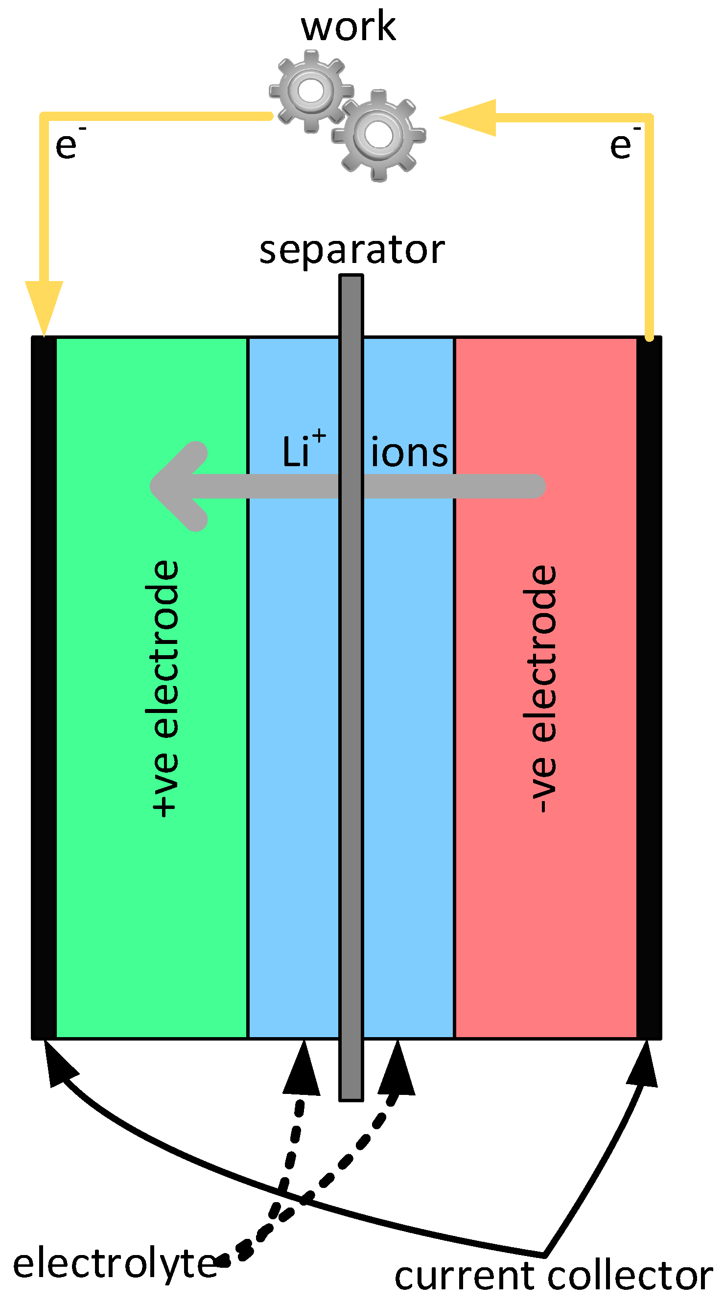
2. The Li-Ion Batteries
2.1. Positive Electrode
2.1.1. Lithium Cobalt Oxide (LiCoO2)
2.1.2. Lithium Nickel Oxide (LiNiO2)
2.1.3. Lithium Manganese Oxide (LiMn2O4)
2.1.4. Lithium Iron Phosphate (LiFePO4)
2.1.5. Lithium Nickel Manganese Cobalt Oxide (Li(NixMnyCo1−x−y)O2)
2.1.6. Lithium Nickel Cobalt Aluminum Oxide (Li(NixCoyAl1−x−y)O2)
2.2. Negative Electrode
2.2.1. Carbon Based Electrodes
2.2.2. Lithium Titanate (Li4Ti5O12)
2.2.3. Lithium Metal
2.2.4. Alloy Based Electrodes
2.2.5. Silicon Based Electrodes
2.2.6. Conversion Electrodes
2.3. Electrolytes
2.3.1. Aqueous Electrolytes
2.3.2. Organic Liquid Electrolytes
2.3.3. Polymer Electrolytes
2.3.4. Ceramic Electrolytes
2.3.5. Solid Electrolyte Interphase
2.4. Physical Implementation of Li-Ion Batteries
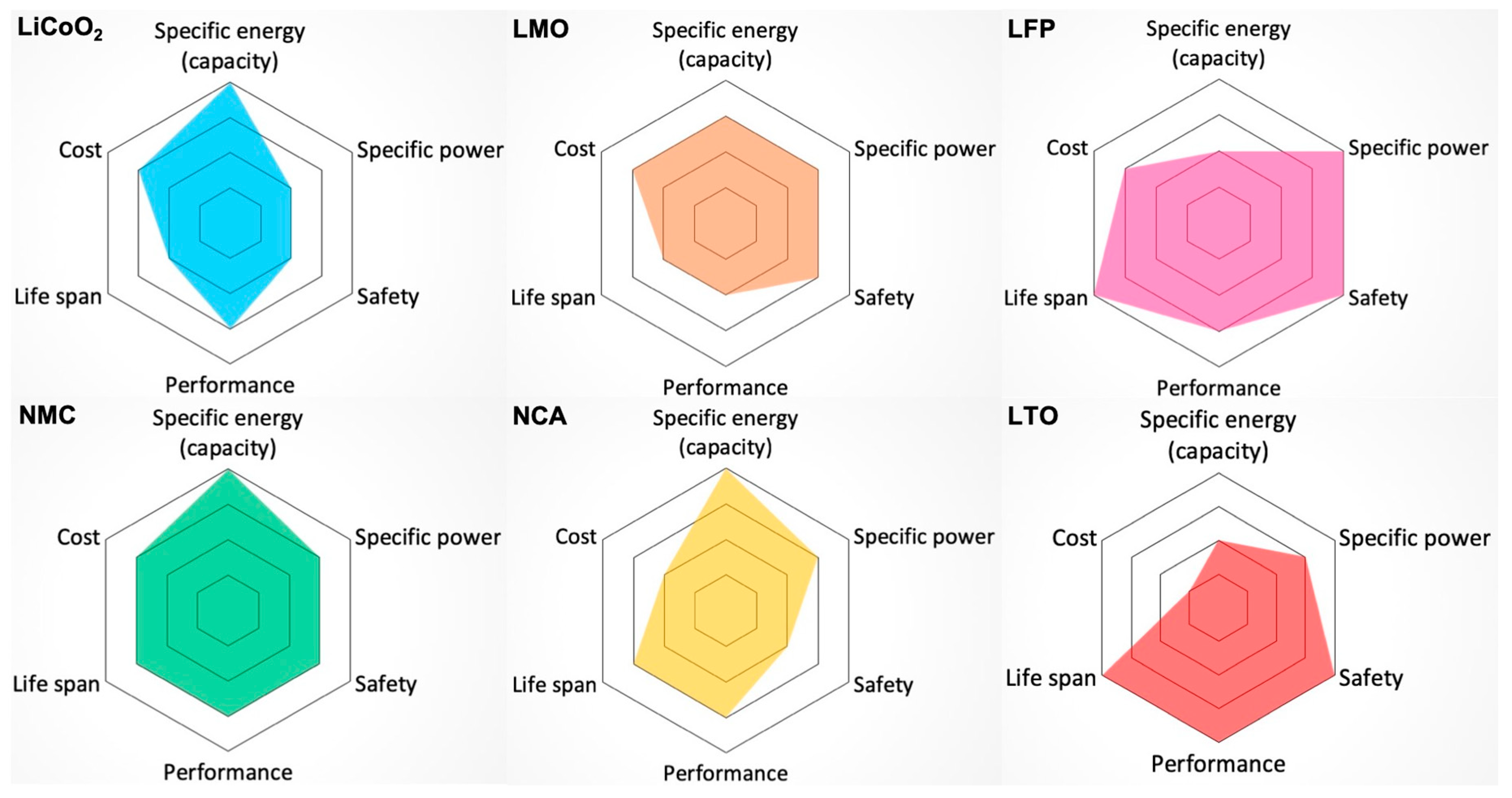
2.5. Comparisons of Different Types of Li-Ion Batteries Used in Electric Vehicles
3. Li-Ion Battery Lifespan
3.1. Temperature
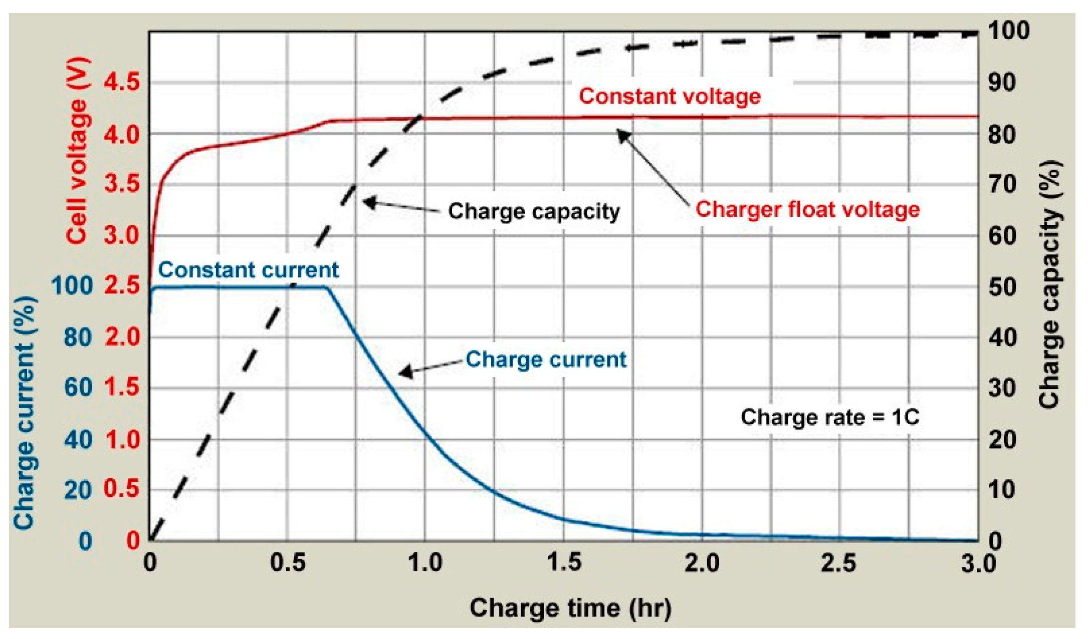
3.2. Charge/Discharge Rate
3.3. Charge/Discharge Depth
3.4. Additonal Ways to Extend the Life of Li-Ion Batteries
4. Recycling and Repurposing
4.1. Recycling
4.2. Repurposing for Power Grid
5. Conclusions
Author Contributions
Funding
Conflicts of Interest
References and Note
- Morimoto, M. Which is the first electric vehicle? Electr. Eng. Jpn. 2015, 192, 31–38. [Google Scholar] [CrossRef]
- History of the Electric Vehicle. Available online: https://en.wikipedia.org/wiki/History_of_the_electric_vehicle (accessed on 16 February 2019).
- World’s First Electric Car Built by Victorian Inventor in 1884. Available online: https://www.telegraph.co.uk/news/newstopics/howaboutthat/5212278/Worlds-first-electric-car-built-by-Victorian-inventor-in-1884.html (accessed on 16 February 2019).
- Thomas, C. Objects to “Chauffeur”. The New York Times. Available online: https://timesmachine.nytimes.com/timesmachine/1902/01/22/101930350.pdf (accessed on 11 February 2019).
- Reeves, M.O.; Reeves, M.T. Exhaust Muffler for Engines. U.S. Patent 582485A, 5 November 1897. [Google Scholar]
- Kettering, C.F. Engine Starting, Lighting and Ignition System. U.S. Patent 1254811A, 29 January 1918. [Google Scholar]
- Mitropoulos, L.K.; Prevedouros, P.D.; Kopelias, P. Total cost of ownership and externalities of conventional, hybrid and electric vehicle. Transp. Res. Proc. 2017, 24, 267–274. [Google Scholar] [CrossRef]
- Maciel, M.; Rosa, L.; Correa, F.; Maruyama, U. Energy, pollutant emissions and other negative externality savings from curbing individual motorized transportation (IMT): A low cost, low technology scenario analysis in Brazilian urban areas. Energies 2012, 5, 835–861. [Google Scholar] [CrossRef]
- Holzman, D.C. Driving up the cost of clean air. Environ. Health Perspect. 2005, 113, A246–A249. [Google Scholar] [CrossRef]
- Samaras, C.; Meisterling, K. Life cycle assessment of greenhouse gas emissions from plug-in hybrid vehicles: Implications for policy. Environ. Sci. Technol. 2008, 42, 3170–3176. [Google Scholar] [CrossRef] [PubMed]
- Holdway, A.R.; Williams, A.R.; Inderwildi, O.R.; King, D.A. Indirect emissions from electric vehicles: Emissions from electricity generation. Energy Environ. Sci. 2010, 3, 1825–1832. [Google Scholar] [CrossRef]
- Tarascon, J.-M.; Armand, M. Issues and challenges facing rechargeable lithium batteries. Nature 2001, 414, 359–367. [Google Scholar] [CrossRef]
- Ragone, D. Review of battery systems for electrically powered vehicles. SAE Tech. Pap. 1968. [Google Scholar] [CrossRef]
- Keshan, H.; Thornburg, J.; Ustun, T.S. Comparison of lead-acid and lithium ion batteries for stationary storage in off-grid energy systems. In Proceedings of the 4th IET Clean Energy and Technology Conference (CEAT 2016), Kuala Lumpur, Malaysia, 14–15 November 2016; Institution of Engineering and Technology (IET): Kuala Lumpur, Malaysia, 2016; pp. 1–7. [Google Scholar]
- Rechargeable Battery. Available online: https://en.wikipedia.org/wiki/Rechargeable_battery (accessed on 17 February 2019).
- Tarascon, J.M. The Li-Ion Battery: 25 Years of Exciting and Enriching Experiences. Electrochem. Soc. Interface 2016, 25, 79–83. [Google Scholar] [CrossRef]
- Sudworth, J.L. The sodium/nickel chloride (ZEBRA) battery. J. Power Sources 2001, 100, 149–163. [Google Scholar] [CrossRef]
- Horiba, T. Li-ion battery systems. Proc. IEEE 2014, 102, 939–950. [Google Scholar] [CrossRef]
- Because the role of anode and cathode reverses between charging (electrolytic) and discharging (galvanic) modes, we will address the electrodes in the context of this paper as the positive electrode and the negative electrode. In some work the positive electrode is generally named the cathode, and the negative electrode the anode regardless of the battery operating mode.
- Hannan, M.A.; Hoque, M.M.; Hussain, A.; Yusof, Y.; Ker, P.J. State-of-the-art and energy management systems of Li-ion batteries in EV applications: Issues and recommendations. IEEE Access 2018, 6, 19362–19378. [Google Scholar] [CrossRef]
- Tesla. Model S Owner’s Manual. Version 2018.48.12. Available online: https://www.tesla.com/sites/default/files/model_s_owners_manual_north_america_en_us.pdf (accessed on 11 February 2019).
- Arora, P.; Zhang, Z. Battery Separators. Chem. Rev. 2004, 104, 4419–4462. [Google Scholar] [CrossRef] [PubMed]
- Lagadec, M.F.; Zahn, R.; Wood, V. Characterization and performance evaluation of Li-ion battery separators. Nat. Energy 2019, 4, 16–25. [Google Scholar] [CrossRef]
- Bandhauer, T.M.; Garimella, S.; Fuller, T.F. A critical review of thermal issues in Li-ion batteries. J. Electrochem. Soc. 2011, 158, R1–R25. [Google Scholar] [CrossRef]
- BU-808c: Coulombic and Energy Efficiency with the Battery. Available online: https://batteryuniversity.com/learn/article/bu_808c_coulombic_and_energy_efficiency_with_the_battery (accessed on 26 February 2019).
- Is Li-Ion the Solution for the Electric Vehicle? Available online: https://batteryuniversity.com/learn/archive/is_li_ion_the_solution_for_the_electric_vehicle (accessed on 5 May 2019).
- Yoon, C.S.; Jun, D.-W.; Myung, S.-T.; Sun, Y.-K. Structural Stability of LiNiO2 Cycled above 4.2 V. ACS Energy Lett. 2017, 2, 1150–1155. [Google Scholar] [CrossRef]
- Kalyani, P.; Kalaiselvi, N.; Muniyandi, N. Microwave assisted synthesis of LiNiO2—A preliminary investigation. J. Power Sources 2003, 123, 53–60. [Google Scholar] [CrossRef]
- Dahn, J.R.; von Sacken, U.; Juzkow, M.W.; Al-Janaby, H. Rechargeable LiNiO2/Carbon Cells. J. Electrochem. Soc. 1991, 138, 2207–2211. [Google Scholar] [CrossRef]
- Muto, S.; Sasano, Y.; Tatsumi, K.; Sasaki, T.; Horibuchi, K.; Takeuchi, Y.; Ukyo, Y. Capacity-Fading Mechanisms of LiNiO2-Based Li-ion Batteries II. Diagnostic Analysis by Electron Microscopy and Spectroscopy. J. Electrochem. Soc. 2009, 156, A371–A377. [Google Scholar] [CrossRef]
- Delmas, C.; Saadoune, I.; Rougier, A. The Cycling Properties of the LixNi1–yCoyO2 Electrode. J. Power Sources 1993, 44, 595–602. [Google Scholar] [CrossRef]
- Reimers, J.N.; Rossen, E.; Jones, C.D.; Dahn, J.R. Structure and Electrochemistry of LixFeyNi1-yO2. Solid State Ion. 1993, 61, 335–344. [Google Scholar] [CrossRef]
- Rossen, E.; Jones, C.D.W.; Dahn, J.R. Structure and Electrochemistry of LixMnyNi1−yO2. Solid State Ion. 1992, 57, 311–318. [Google Scholar] [CrossRef]
- Ohzuku, T.; Ueda, A.; Kouguchi, M. Synthesis and Characterization of LiAl1/4Ni3/4O2(R3m) for Li-ion (Shuttlecock) Batteries. J. Electrochem. Soc. 1995, 142, 4033–4039. [Google Scholar] [CrossRef]
- Subramanian, V.; Fey, G.T.-K. Preparation and Characterization of LiNi0.7Co0.2Ti0.05M0.05O2 (M = Mg, Al and Zn) Systems as Cathode Materials for Lithium Batteries. Solid State Ion. 2002, 148, 351–358. [Google Scholar] [CrossRef]
- Pouillerie, C.; Croguennec, L.; Delmas, C. The LixNi1–yMgyO2 (y = 0.05, 0.10) System: Structural Modifications Observed upon Cycling. Solid State Ion. 2000, 132, 15–29. [Google Scholar] [CrossRef]
- Thackeray, M.M.; David, W.I.F.; Bruce, P.G.; Goodenough, J.B. Lithium insertion into manganese spinels. Mater. Res. Bull. 1983, 18, 461–472. [Google Scholar] [CrossRef]
- BU-205: Types of Li-Ion. Available online: https://batteryuniversity.com/learn/article/types_of_lithium_ion (accessed on 5 May 2019).
- Johnson, C.S.; Li, N.; Vaughey, J.T.; Hackney, S.A.; Thackeray, M.M. Lithium-manganese oxide electrodes with layered-spinel composite structures xLi2MnO3∙(1 − x)Li1+yMn2−yO4 (0 < x < 1, 0 ≤ y ≤ 0.33) for lithium batteries. Electrochem. Commun. 2005, 7, 528–536. [Google Scholar] [CrossRef]
- Sun, C.; Rajasekhara, S.; Goodenough, J.B.; Zhou, F. Monodisperse porous LiFePO4 microspheres for a high power Li-ion battery cathode. J. Am. Chem. Soc. 2011, 133, 2132–2135. [Google Scholar] [CrossRef]
- Harrison, K.L.; Bridges, C.A.; Paranthaman, M.P.; Segre, C.U.; Katsoudas, J.; Maroni, V.A.; Idrobo, J.C.; Goodenough, J.B.; Manthiram, A. Temperature dependence of aliovalent-vanadium doping in LiFePO4 cathodes. Chem. Mater. 2013, 25, 768–781. [Google Scholar] [CrossRef]
- All-electric Iridium E Mobil Motorhome Is Coming to Market. Available online: https://electrek.co/2018/12/10/electric-motorhome-iridium-e-mobil/ (accessed on 5 May 2019).
- Exciting Developments in NMC811 Lithium Battery Technology. Available online: https://cleantechnica.com/2018/03/04/exciting-developments-nmc-811-lithium-battery-technology/ (accessed on 5 May 2019).
- Six Li-ion Battery Chemistries: Not All Batteries are Created Equal. Available online: https://www.powerelectronics.com/alternative-energy/six-Li-ion-battery-chemistries-not-all-batteries-are-created-equal (accessed on 5 May 2019).
- Why Tesla’s Grid Batteries Will Use Two Different Chemistries. Available online: http://fortune.com/2015/05/18/tesla-grid-batteries-chemistry/ (accessed on 11 February 2019).
- Tesla Panasonic Quietly Outmaneuver All Lithium Battery Manufacturers. Available online: https://insideevs.com/tesla-panasonic-quietly-outmaneuvers-all-lithium-battery-manufacturers/ (accessed on 5 May 2019).
- Kinoshita, K.; Zaghib, K. Negative Electrodes for Li-ion Batteries. J. Power Sources 2002, 110, 416–423. [Google Scholar] [CrossRef]
- Mao, C.; Wood, M.; David, L.; An, S.J.; Sheng, Y.; Du, Z.; Meyer, H.M., III; Ruther, R.E.; Wood, D.L., III. Selecting the Best Graphite for Long-Life, High-Energy Li-Ion Batteries. J. Electrochem. Soc. 2018, 165, A1837–A1845. [Google Scholar] [CrossRef]
- Shuai, C. Self-supported Li4Ti5O12 nanosheet arrays for lithium ion batteries with excellent rate capability and ultralong cycle life. Energy Environ. Sci. 2014, 7, 1924–1930. [Google Scholar] [CrossRef]
- Mitsubishi Choose Super-Efficient Toshiba SCiB Battery for EVs. Available online: https://integrityexports.com/blog/mitsubishi-chooses-toshiba-scib-battery-for-evs/ (accessed on 5 May 2019).
- Toshiba’s SCiB Battery for the Fit EV. Available online: https://www.greencarcongress.com/2011/11/scib-20111117.html (accessed on 5 May 2019).
- Auge, O. TOSA concept: A full electric large capacity urban bus system. In Proceedings of the 17th European Conference on Power Electronics and Applications (EPE’15 ECCE-Europe), Geneva, Switzerland, 8–10 September 2015. [Google Scholar]
- All About Batteries, Part 12: Lithium Titanate (LTO). Available online: https://www.eetimes.com/author.asp?section_id=36&doc_id=1325358# (accessed on 5 May 2019).
- Zhang, J.; Xu, W.; Henderson, W.A. Lithium Metal Anodes and Rechargeable Lithium Metal Batteries; Springer: Basel, Switzerland, 2016; pp. 5–43. [Google Scholar]
- Cheng, X.-B.; Zhang, R.; Zhao, C.-Z.; Zhang, Q. Toward Safe Lithium Metal Anode in Rechargeable Batteries: A Review. Chem. Rev. 2017, 117, 10403–10473. [Google Scholar] [CrossRef] [PubMed]
- Xu, W.; Wang, J.; Ding, F.; Chen, X.; Nasybulin, E.; Zhang, Y.; Zhang, J.-G. Lithium Metal Anodes for Rechargeable Batteries. Energy Environ. Sci. 2014, 7, 513–537. [Google Scholar] [CrossRef]
- Cheng, X.-B.; Zhang, Q. Dendrite-Free Lithium Metal Anodes: Stable Solid Electrolyte Interphases for High-Efficiency Batteries. J. Mater. Chem. A 2015, 3, 7207–7209. [Google Scholar] [CrossRef]
- Wang, M.; Zhang, F.; Lee, C.-S.; Tang, Y. Low-Cost Metallic Anode Materials for High Performance Rechargeable Batteries. Adv. Energy Mater. 2017, 7. [Google Scholar] [CrossRef]
- Nazar, L.F.; Crosnier, O. Anodes and Composite Anodes: An Overview. In Lithium Batteries Science and Technology; Nazri, G.-A., Pistoia, G., Eds.; Springer: New York, NY, USA, 2004; pp. 112–143. [Google Scholar]
- Lai, S.-C. Solid Lithium-Silicon Electrode. J. Electrochem. Soc. 1976, 123, 1196–1197. [Google Scholar] [CrossRef]
- Obrovac, M.N.; Christensen, L. Structural Changes in Silicon Anodes during Lithium Insertion/Extraction. Electrochem. Solid-State Lett. 2004, 7, A93–A96. [Google Scholar] [CrossRef]
- Gu, M.; He, Y.; Zheng, J.M.; Wang, C.M. Nanoscale silicon as anode for Li-ion batteries: The fundamentals, promises, and challenges. Nano Energy 2015, 17, 366–383. [Google Scholar] [CrossRef]
- Ding, N.; Xu, J.; Yao, Y.X.; Wegner, G.; Fang, X.; Chen, C.H.; Lieberwirth, I. Determination of the Diffusion Coefficient of Lithium Ions in Nano-Si. Solid State Ion. 2009, 180, 222–225. [Google Scholar] [CrossRef]
- Liu, X.H.; Zhong, L.; Huang, S.; Mao, S.X.; Zhu, T.; Huang, J.Y. Size-Dependent Fracture of Silicon Nanoparticles during Lithiation. ACS Nano 2012, 6, 1522–1531. [Google Scholar] [CrossRef] [PubMed]
- Domi, Y.; Usui, H.; Yamaguchi, K.; Yodoya, S.; Sakaguchi, H. Silicon-Based Anodes with Long Cycle Life for Li-ion Batteries Achieved by Significant Suppression of their Volume Expansion in Ionic-Liquid Electrolyte. ACS Appl. Mater. Interfaces 2019, 11, 2950–2960. [Google Scholar] [CrossRef]
- Obrovac, M.N.; Krause, L.J. Reversible Cycling of Crystalline Silicon Powder. J. Electrochem. Soc. 2007, 154, A103–A108. [Google Scholar] [CrossRef]
- Schneider, D. To Boost Li-ion Battery Capacity by up to 70%, Add Silicon. 2019. Available online: https://spectrum.ieee.org/energy/renewables/to-boost-lithiumion-battery-capacity-by-up-to-70-add-silicon (accessed on 12 February 2019).
- Yu, S.-H.; Feng, X.; Zhang, N.; Seok, J.; Abruña, H.D. Understanding Conversion-Type Electrodes for Lithium Rechargeable Batteries. Acc. Chem. Res. 2018, 51, 273–281. [Google Scholar] [CrossRef] [PubMed]
- Zhang, L.; Wei, Q.; Sun, D.; Li, N.; Ju, H.; Feng, J.; Zhu, J.; Mai, L.; Cairns, E.J.; Guo, J. Conversion reaction of vanadium sulfide electrode in the Li-ion cell: Reversible or not reversible? Nano Energy 2018, 51, 391–399. [Google Scholar] [CrossRef]
- Ren, Q.-Q.; Wang, Z.-B.; Ke, K.; Zhang, S.-W.; Yin, B.-S. NiCO2O4 nanosheets and nanocones as additive-free anodes for high-performance Li-ion batteries. Ceram. Int. 2017, 43, 13710–13716. [Google Scholar] [CrossRef]
- Yu, S.-H.; Lee, S.H.; Lee, D.J.; Sung, Y.-E.; Hyeon, T. Conversion Reaction-Based Oxide Nanomaterials for Lithium Ion Battery Anodes. Small 2016, 12, 2146–2172. [Google Scholar] [CrossRef] [PubMed]
- Manthiram, A.; Yu, X.; Wang, S. Lithium battery chemistries enabled by solid-state electrolytes. Nat. Rev. Mater. 2016, 2. [Google Scholar] [CrossRef]
- Suo, L.; Borodin, O.; Gao, T.; Olguin, M.; Ho, J.; Fan, X.; Luo, C.; Wang, C.; Xu, K. “Water-in-salt” electrolyte enables high-voltage aqueous Li-ion chemistries. Science 2015, 350, 938–943. [Google Scholar] [CrossRef] [PubMed]
- Younesi, R.; Veith, G.M.; Johansson, P.; Edström, K.; Vegge, T. Lithium salts for advanced lithium batteries: Li–metal, Li–O2, and Li–S. Energy Environ. Sci. 2015, 8, 1905–1922. [Google Scholar] [CrossRef]
- MacFarlane, D.R.; Forsyth, M.; Howlett, P.C.; Kar, M.; Passerini, S.; Pringle, J.M.; Ohno, H.; Watanabe, M.; Yan, F.; Zheng, W.; et al. Ionic liquids and their solid-state analogues as materials for energy generation and storage. Nat. Rev. Mater. 2016, 1. [Google Scholar] [CrossRef]
- Eshetu, G.G.; Grugeon, S.; Laruelle, S.; Boyanov, S.; Lecocq, A.; Bertrand, J.-P.; Marlair, G. In-depth safety-focused analysis of solvents used in electrolytes for large scale lithium ion batteries. Phys. Chem. Chem. Phys. 2013, 15, 9145–9155. [Google Scholar] [CrossRef] [PubMed]
- Que, M.; Tong, Y.; Wei, G.; Yuan, K.; Wei, J.; Jiang, Y.; Zhu, H.; Chen, Y. Safe and flexible ion gel based composite electrolyte for lithium batteries. J. Mater. Chem. A 2016, 4, 14132–14140. [Google Scholar] [CrossRef]
- Zheng, F.; Masashi Kotobuki, M.; Song, S.; Lai, M.O.; Lu, L. Review on solid electrolytes for all-solid-state Li-ion batteries. J. Power Sources 2018, 389, 198–213. [Google Scholar] [CrossRef]
- Kamaya, N. A lithium superionic conductor. Nat. Mater. 2011, 10, 682–686. [Google Scholar] [CrossRef] [PubMed]
- Peled, E.; Golodnitsky, D.; Ardel, G. Advanced model for solid electrolyte interphase electrodes in liquid and polymer electrolytes. J. Electrochem. Soc. 1997, 144, L208–L210. [Google Scholar] [CrossRef]
- Aurbach, D.; Markovsky, B.; Levi, M.D.; Levi, E.; Schechter, A.; Moshkovich, M.; Cohen, Y. New insights into the interactions between electrode materials and electrolyte solutions for advanced nonaqueous batteries. J. Power Sources 1999, 81, 95–111. [Google Scholar] [CrossRef]
- Winter, M. The Solid Electrolyte Interphase—The Most Important and the Least Understood Solid Electrolyte in Rechargeable Li Batteries. Z. Phys. Chem. 2009, 223, 1395–1406. [Google Scholar] [CrossRef]
- Wang, A.; Kadam, S.; Li, H.; Shi, S.; Qi, Y. Review on modeling of the anode solid electrolyte interphase (SEI) for Li-ion batteries. Comput. Mater. 2018, 4, 15. [Google Scholar] [CrossRef]
- Choi, J.W.; Aurbach, D. Promise and reality of post-Li-ion batteries with high energy densities. Nat. Rev. Mater. 2016, 1. [Google Scholar] [CrossRef]
- Palacín, M.R.; de Guibert, A. Why do batteries fail? Science 2016, 351. [Google Scholar] [CrossRef]
- Hall, J.; Lin, T.; Brown, G.; Biensan, P.; Bonhomme, F. Decay Processes and Life Predictions for Lithium Ion Satellite Cells. In Proceedings of the 4th International Energy Conversion Engineering Conference and Exhibit (IECEC), San Diego, CA, USA, 26–29 January 2006; pp. 2006–4078. [Google Scholar]
- El Mejdoubi, A.; Chaoui, H.; Gualous, H.; Van Den Bossche, P.; Omar, N.; Van Mierlo, J. Li-ion Batteries Health Prognosis Considering Aging Conditions. IEEE Trans. Power Electron. 2019. [Google Scholar] [CrossRef]
- Vetter, J.; Novák, P.; Wagner, M.R.; Veit, C.; Möller, K.-C.; Besenhard, J.; Winter, M.; Wohlfahrt-Mehrens, M.; Vogler, C. Hammouche Ageing mechanisms in Li-ion batteries. J. Power Sources 2005, 147, 269–281. [Google Scholar] [CrossRef]
- Broussely, M.; Biensan, P.; Bonhomme, F.; Blanchard, P.; Herreyre, S.; Nechev, K.; Staniewicz, R.J. Main aging mechanisms in Li ion batteries. J. Power Sources 2005, 146, 90–96. [Google Scholar] [CrossRef]
- Redondo-Iglesias, E.; Venet, P.; Pelissier, S. Efficiency Degradation Model of Li-ion Batteries for Electric Vehicles. IEEE Trans. Ind. Appl. 2019. [Google Scholar] [CrossRef]
- Lin, Y.-X.; Liu, Z.; Leung, K.; Chen, L.-Q.; Lu, P.; Qi, Y. Connecting the irreversible capacity loss in Li-ion batteries with the electronic insulating properties of solid electrolyte interphase (SEI) components. J. Power Sources 2016, 309, 221–230. [Google Scholar] [CrossRef]
- Rahimi-Eichi, H.; Ojha, U.; Baronti, F.; Chow, M.-Y. Battery management system: An overview of its application in the smart grid and electric vehicles. IEEE Ind. Electron. Mag. 2013, 7, 4–16. [Google Scholar] [CrossRef]
- Topan, P.A.; Ramadan, M.N.; Fathoni, G.; Cahyadi, A.I.; Wahyunggoro, O. State of charge (SOC) and state of health (SOH) estimation on lithium polymer battery via Kalman filter. In Proceedings of the 2nd International Conference on Science and Technology-Computer (ICST), Yogyakarta, Indonesia, 27–28 October 2016; pp. 93–96. [Google Scholar]
- Zhao, R.; Zhang, S.; Liu, J.; Gu, J. A review of thermal performance improving methods of lithium ion battery: Electrode modification and thermal management system. J. Power Sources 2015, 299, 557–577. [Google Scholar] [CrossRef]
- Wang, Q.; Ping, P.; Zhao, X.; Chu, G.; Sun, J.; Chen, C. Thermal runaway caused fire and explosion of lithium ion battery. J. Power Sources 2012, 208, 210–224. [Google Scholar] [CrossRef]
- Boeing 787 Dreamliner Battery Problems. Available online: https://en.wikipedia.org/wiki/Boeing_787_Dreamliner_battery_problems (accessed on 17 February 2019).
- Plug-in Electric Vehicle Fire Incidents. Available online: https://en.wikipedia.org/wiki/Plug-in_electric_vehicle_fire_incidents (accessed on 17 February 2019).
- Burke, A.; Jungers, B.; Yang, C.; Ogden, J. Battery Electric Vehicles: An Assessment of the Technology and Factors Influencing Market Readiness; Advanced Energy Pathway (AEP) Project; Public Interest Energy Research (PIER) Program California Energy Commission: Sacramento, CA, USA, 2007.
- Haiying, W.; Feng, W.; Ying, F.; Ran, L.; Qian, Z. Study on key technologies of lithium battery for electric vehicle. In Proceedings of the 6th International Forum on Strategic Technology (IFOST), Harbin, China, 22–24 August 2011; pp. 291–294. [Google Scholar] [CrossRef]
- Corrigan, D.A.; Masias, A. Batteries for electric and hybrid vehicles. In Linden’s Handbook of Batteries, 4th ed.; Reddy, T.B., Ed.; McGraw-Hill: New York, NY, USA, 2011. [Google Scholar]
- Cheng, K.W.E.; Divakar, B.P.; Wu, H.; Ding, K.; Ho, H.F. Battery-management system (BMS) and SOC development for electric vehicles. IEEE Trans. Veh. Technol. 2011, 60, 76–88. [Google Scholar] [CrossRef]
- Leng, F.; Tan, C.M.; Pecht, M. Effect of Temperature on the Aging rate of Li Ion Battery Operating above Room Temperature. Sci. Rep. 2015, 5, 12967. [Google Scholar] [CrossRef]
- Zhang, C.; Jiang, J.; Zhang, L.; Liu, S.; Wang, L.; Loh, P.C. A generalized SOC-OCV model for Li-ion batteries and the SOC estimation for LNMCO battery. Energies 2016, 9, 900. [Google Scholar] [CrossRef]
- Zhang, C.; Wang, L.Y.; Li, X.; Chen, W.; Yin, G.; Jiang, J. Robust and adaptive estimation of state of charge for Li-ion batteries. IEEE Trans. Ind. Electron. 2015, 62, 4948–4957. [Google Scholar] [CrossRef]
- BU-409: Charging Li-Ion. Available online: https://batteryuniversity.com/learn/article/charging_lithium_ion_batteries (accessed on 17 February 2019).
- Al-karakchi, A.A.; Lacey, G.; Putrus, G. A method of electric vehicle charging to improve battery life. In Proceedings of the 50th International Universities Power Engineering Conference (UPEC), Stoke on Trent, UK, 1–4 September 2015; pp. 1–3. [Google Scholar] [CrossRef]
- Battery Lifetime: How Long Can Electric Vehicle Batteries Last? Available online: https://cleantechnica.com/2016/05/31/battery-lifetime-long-can-electric-vehicle-batteries-last/ (accessed on 17 February 2019).
- BU-402: What Is C-Rate? Available online: https://batteryuniversity.com/learn/article/what_is_the_c_rate (accessed on 26 February 2019).
- Collin, R.; von Jouanne, A.; Yokochi, A.; Enjeti, P. Advanced Electric Vehicle Fast-charging Technologies. Energies 2019, in press. [Google Scholar]
- Adegbohun, J.; von Jouanne, A.; Lee, K. Autonomous Battery Swapping System and Methodologies of Electric Vehicles. Energies 2019, 12, 667. [Google Scholar] [CrossRef]
- Abdel-Monem, M.; Hegazy, O.; Omar, N.; Trad, K.; Van den Bossche, P.; Van Mierlo, J. Li-ion batteries: Comprehensive technical analysis of second-life batteries for smart grid applications. In Proceedings of the 19th European Conference on Power Electronics and Applications (EPE’17 ECCE Europe), Warsaw, Poland, 11–14 September 2017; pp. 1–16. [Google Scholar]
- Croy, J.R.; Balasubramanian, M.; Gallagher, K.G.; Burrell, A.K. Review of the U.S. Department of Energy’s “Deep Dive” Effort to Understand Voltage Fade in Li- and Mn-Rich Cathodes. Acc. Chem. Res. 2015, 48, 2813–2821. [Google Scholar] [CrossRef]
- BU-808: How to Prolong Lithium-Based Batteries. Available online: https://batteryuniversity.com/learn/article/how_to_prolong_lithium_based_batteries (accessed on 17 February 2019).
- EV Tech Explained: Why Do EVs Restrict the Amount of Battery Capacity That Can Be Used for Driving? Available online: https://chargedevs.com/newswire/ev-tech-explained-why-do-evs-restrict-the-amount-of-battery-capacity-that-can-be-used-for-driving/ (accessed on 17 February 2019).
- Lead–Acid Battery. Available online: https://en.wikipedia.org/wiki/Lead–acid_battery (accessed on 17 February 2019).
- Zhou, X.; He, W.-Z.; Li, G.-M.; Zhang, X.-J.; Zhu, S.-G.; Huang, J.W.; Zhu, S.-G. Recycling of Electrode Materials from Spent Li-ion Batteries. In Proceedings of the 4th International Conference on Bioinformatics and Biomedical Engineering, Chengdu, China, 18–20 June 2010; pp. 1–4. [Google Scholar] [CrossRef]
- Ciez, R.E.; Whitacre, J.F. Examining different recycling processes for Li-ion batteries. Nat. Sustain. 2019, 2, 148–156. [Google Scholar] [CrossRef]
- Tytgat, J. The recycling efficiency of Li-ion EV batteries according to the European Commission regulation, and the relation with the end-of-life vehicles directive recycling rate. In Proceedings of the World Electric Vehicle Symposium and Exhibition (EVS27), Barcelona, Spain, 17–20 November 2013; pp. 1–9. [Google Scholar] [CrossRef]


| Shape | Cylindrical | Prismatic | Pouch |
|---|---|---|---|
| Diagram |  |  |  |
| Electrode Arrangement | Wound | Wound | Stacked |
| Mechanical Strength | ++ | + | − |
| Heat Management | − | + | + |
| Specific Energy | + | + | ++ |
| Energy Density | + | ++ | + |
| Components of BMS | Functional Details of Each Component |
|---|---|
| Measurement Block | capture individual cell voltages, battery current, and battery temperature at different points of the battery bank, as well as the ambient temperature, and convert them into digital values |
| Battery Algorithm Block | estimate state of charge (SOC) 1 and state of health (SOH) 2 using the measured battery variables such as battery voltage, current, and temperature |
| Capability Estimation Block | send information to the engine control unit (ECU) about the present safe level of charging and discharging current of the battery |
| Cell Equalization Block | compare the cell voltages, find the difference between the highest and lowest cell voltage, and apply cell balancing techniques |
| Thermal Management Block | read ambient and battery temperatures, initiate cooling or heating operation, and send an emergency signal to ECU in case of abnormal rise in temperature |
| Depth of Discharge | Discharge Cycles (NMC/LiPO4) |
|---|---|
| 100% | 300–600 |
| 80% | 400–900 |
| 60% | 600–900 |
| 40% | 1000–3000 |
| 20% | 2000–9000 |
| 10% | 6000–15,000 |
© 2019 by the authors. Licensee MDPI, Basel, Switzerland. This article is an open access article distributed under the terms and conditions of the Creative Commons Attribution (CC BY) license (http://creativecommons.org/licenses/by/4.0/).
Share and Cite
Miao, Y.; Hynan, P.; von Jouanne, A.; Yokochi, A. Current Li-Ion Battery Technologies in Electric Vehicles and Opportunities for Advancements. Energies 2019, 12, 1074. https://doi.org/10.3390/en12061074
Miao Y, Hynan P, von Jouanne A, Yokochi A. Current Li-Ion Battery Technologies in Electric Vehicles and Opportunities for Advancements. Energies. 2019; 12(6):1074. https://doi.org/10.3390/en12061074
Chicago/Turabian StyleMiao, Yu, Patrick Hynan, Annette von Jouanne, and Alexandre Yokochi. 2019. "Current Li-Ion Battery Technologies in Electric Vehicles and Opportunities for Advancements" Energies 12, no. 6: 1074. https://doi.org/10.3390/en12061074
APA StyleMiao, Y., Hynan, P., von Jouanne, A., & Yokochi, A. (2019). Current Li-Ion Battery Technologies in Electric Vehicles and Opportunities for Advancements. Energies, 12(6), 1074. https://doi.org/10.3390/en12061074