Article

Low Power Consumption Signal Detector Based on Adaptive DFSD in MIMO-OFDM Systems

uT Communication Research Institute, Sejong University, Gunja-dong 98, Gwangjin-gu, Seoul 05006, Korea
*
Author to whom correspondence should be addressed.
Energies 2019, 12(4), 599; https://doi.org/10.3390/en12040599
Submission received: 17 December 2018 / Revised: 31 January 2019 / Accepted: 11 February 2019 / Published: 14 February 2019
(This article belongs to the Section F: Electrical Engineering)

Abstract

:
For a low complexity signal detector to reduce the power consumption for multiple input and multiple output orthogonal frequency division multiplexing (MIMO-OFDM) systems, the depth-first sphere decoding (DFSD) detection scheme was proposed. However, the DFSD detection scheme still has high complexity in the hardware implementation. The complexity is especially high when the signal-to-noise ratio (SNR) is low. Therefore, this paper proposes an adaptive DFSD detection scheme. The proposed detection scheme arrays nodes, sorting by ascending order of squared Euclidean distance (ED) at the top layer of tree structure. Then, the proposed detection scheme uses the different number of nodes according to thresholds based on channel condition. In the simulation results, the proposed detection scheme has similar error performance and low complexity compared with the conventional DFSD detection scheme. Therefore, the proposed detection scheme reduces the power consumption in the signal detector.

1. Introduction

Wireless communication technology has evolved as demand for increasing the data rate has grown. Multiple input and multiple output (MIMO) based on orthogonal frequency division multiplexing (OFDM) systems can increase the capacity of wireless communication by using multiple antennas, and improve link reliability in transferring data [1,2,3]. To maximize these benefits, the design of the receiver is important. The purpose of the receiver is to detect the signal exactly and to reduce the complexity of signal detection. In 5G wireless infrastructure, because the number of antennas and the required data rate has increased, the required power consumption increases rapidly at the signal detector. So, it is needed to lower the power consumption by reducing the complexity. The linear signal detection algorithms of MIMO-OFDM systems are zero forcing (ZF) and minimum mean square error (MMSE) detection schemes [4,5]. The ZF and the MMSE detection schemes have low complexity. However, the detection performance of these schemes is not good from the bit error rate (BER) point of view. Other types of detection schemes include non-linear detection schemes such as decision feedback equalization (DFE), ordered successive interference cancellation (OSIC) detection schemes, and so on [6,7]. The DFE and the OSIC detection schemes have better error performance than the ZF and the MMSE detection schemes. In contrast, the complexity of these non-linear detection schemes is high compared to the ZF and the MMSE detection schemes. The optimal signal detection scheme for the MIMO-OFDM systems is the maximum likelihood (ML) detection scheme [8,9]. However, the complexity of the ML detection scheme is very high when the modulation order or the number of transmit antennas increases. So, many researchers have studied the schemes to detect the signal, having similar error performance and low complexity compared to the ML detection scheme. Moreover, the non-linear detection algorithm using DFSD algorithm was proposed. The DFSD detection scheme has suboptimal performance compared to the ML detection scheme [10,11,12,13]. Also, the DFSD detection scheme has lower complexity than the ML detection scheme. However, the DFSD detection scheme still has high complexity in the hardware implementation. In order to overcome these disadvantages, this paper proposes an adaptive DFSD detection scheme, which has low complexity compared to the conventional DFSD detection scheme.
The adaptive DFSD detection scheme uses thresholds based on channel condition to vary the number of top layer nodes of DFSD tree structure. When the DFSD detection scheme uses one node at the top layer, error performance is not good compared to the DFSD detection scheme using full nodes at the top layer. But, the complexity of the DFSD detection scheme using one node at the top layer is lower than the DFSD detection scheme using full nodes at the top layer. In OFDM symbols, if subcarriers suffer from a poorly conditioned channel, full nodes are used at the top layer, like the conventional DFSD detection scheme. But, one node is used at the top layer when the channel has the best condition. In the case of a general conditioned channel, the number of nodes varies depending on the channel condition. By using the proposed method, the adaptive DFSD detection scheme has little error performance degradation and significantly less complexity.

2. System Model

Figure 1 shows the MIMO-OFDM system model. At the transmitter, the data is divided into sub-streams by serial to parallel and each sub-stream is mapped to digital modulation symbols. Each symbol is transformed into the time-domain symbols by inverse fast Fourier transform (IFFT). Then, the cyclic prefix (CP) is added to reduce inter-symbol interference (ISI) and inter-carrier interference (ICI). These symbols pass through a Rayleigh fading channel. The baseband equivalent model for the MIMO-OFDM systems is as follows,
Y = H X + N ,
where Y = y 1 , y 2 , , y N r T is the N r × 1 receive symbol vector. X = x 1 , x 2 , , x N t T is the N t × 1 transmit symbol vector. N is the N r × 1 complex zero-mean Gaussian noise vector. · T denotes transpose matrix. A complex channel matrix H is denoted as follows,
H = h 11 h 12 h 1 N t h 21 h 22 h 2 N t h N r 1 h N r 2 h N r N t ,
where an element h i j ( i = 1 , 2 , , N r ) , ( j = 1 , 2 , , N t ) denotes channel coefficient from the j-th transmit antenna to the i-th receive antenna. Also, each element h i j is independent and identically distributed (i.i.d) random variables. At the receiver, CP is removed to process the reverse transmitter. Each symbol is transformed into the frequency domain symbol by fast Fourier transform (FFT). Then, these symbols pass through the detector to demodulate the original data.

3. Conventional Signal Detection Schemes

3.1. Maximum Likelihood Detection

The ML detection scheme tries to look for the optimal X ^ that has a minimum value of Y H X ^ 2 . The general equation of ML detection is as follows,
X ^ M L = arg min x S N t Y HX 2 ,
where S denotes the set of constellation points of transmitter symbols. S N t denotes the space of transmission signal vector. The ML detection scheme has optimal error performance, so we considered using this detection scheme at the receiver. But, because the complexity of ML detection scheme increases in proportion to the number of S N t , it is difficult to implement at the receiver.

3.2. Conventional Depth-First Sphere Decoding

The DFSD detection scheme has similar error performance to the ML detection scheme with a low complexity. The DFSD detection scheme is restricted to the search area of the ML detection scheme in a sphere with radius of C and centers around the received symbol. The DFSD detection scheme inequality is as follows [14,15,16],
Y HX 2 C 2 ,
where C is sphere radius. Because it is hard to determine which lattice nodes lay inside of the m-dimensional sphere, the DFSD detection scheme is represented at the tree structure. Before the DFSD detection scheme searches the received symbol Y , QR-decomposition is performed from the complex channel matrix H . The equation of channel matrix is as follows,
H = QR ,
where Q is the N r × N r unitary matrix and R is the N r × N t upper triangular matrix. To remove the elements of Q , Equation (1) is multiplied by Q H as follows,
Z = Q H Y = Q H ( HX + N ) = RX + Q H N ,
Z = r 11 r 12 r 1 N t 0 r 22 r 2 N t 0 0 0 r N t N t 0 0 0 0 0 0 0 x 1 x 2 x N t + n ˜ 1 n ˜ 2 n ˜ N r ,
where ( · ) H denotes the Hermitian transpose, Z denotes the altered received signal vector and n ˜ i ( i = 1 , 2 , , N r ) denotes the elements of the altered noise vector. The object of DFSD detection scheme is to find the first radius in a depth direction at the tree structure. So, this detection scheme uses a squared Euclidean distance (ED). The squared ED is represented as follows,
d N t ( k ) = z N t r N t N t s ( k ) 2 ,
where d N t ( k ) is the k-th squared ED at the N t -th layer, z N t is the element of altered received signal vector, r N t N t is the element of R matrix and s ( k ) ( k = 1 , 2 , , S ) is the reference symbol. At the ( N t 1 ) -th layer, to consider the exact signal estimation, the DFSD detection scheme uses the accumulated squared ED as follows,
d N t 1 t ( k ) = z N t 1 r N t 1 N t 1 s ( k ) + r N t 1 N t x ^ N t t 2 + d N t ( k ) ,
where x ^ N t t is the t-th estimated symbol among the reference symbols at the N t -th layer. The Equation (9) is generalized to express the n-th layer ( 1 n N t 1 ) as follows,
d n t ( k ) = z n r n n s ( k ) + l = n + 1 N t r n l x ^ l t 2 + d n + 1 t ( k n + 1 ) ,
where x ^ l t is the t-th estimated symbol among the reference symbols from the N t -th layer to the ( n + 1 ) -th layer and d n + 1 t ( k n + 1 ) is the k n + 1 -th accumulated squared ED from the N t -th layer to the ( n + 1 ) -th layer.
Figure 2 shows DFSD tree structure in a 4 × 4 MIMO-OFDM system with quadrature phase shift keying (QPSK) modulation. There are too many metrics to include in Figure 2. So, several metrics are omitted through the dotted lines. Real numbers at the side of each metric are accumulated squared ED. At the first stage, squared ED of Equation (8) is calculated at the N t -th layer, then, the DFSD detection scheme selects the node which has the shortest squared ED. At the next layer, this detection scheme calculates the accumulated squared ED from the selected node of the N t -th layer to the candidate symbol nodes of the ( N t 1 ) -th layer. The DFSD detection scheme selects the node that has the shortest accumulated squared ED at the ( N t 1 ) -th layer. In this way, the DFSD detection scheme repeats the approach of getting the shortest accumulated squared ED by the last layer. Finally, the shortest accumulated squared ED sets the first radius distance [17]. The first radius distance becomes the standard to compare the other accumulated squared ED of each layer for finding the shorter radius distance. If the new accumulated squared ED by the last layer is shorter than the first radius distance, the new accumulated squared ED by the last layer becomes new radius distance. So, the DFSD detection scheme reduces the complexity by updating the radius distance [10]. Also, if the accumulated squared ED at the middle of layer is longer than the updated radius distance, this path is pruned. In this way, by updating the radius distance and pruning the path when the accumulated squared ED is longer than the updated radius distance, the DFSD detection scheme finds the path of the shortest accumulated squared ED and this path includes the reference symbols of corresponding nodes. Transmit symbols are estimated through the reference symbols.

4. Proposed Adaptive DFSD Detection Scheme

The conventional DFSD detection scheme is known as a suboptimal detection scheme because it has almost the same error performance and low complexity compared to the ML detection scheme. However the DFSD detection scheme has still high complexity in the hardware implementation. This paper proposes a new adaptive DFSD detection scheme to reduce the complexity.

4.1. The Adaptive DFSD Detection Scheme According to the Number of Nodes at the N t -th Layer

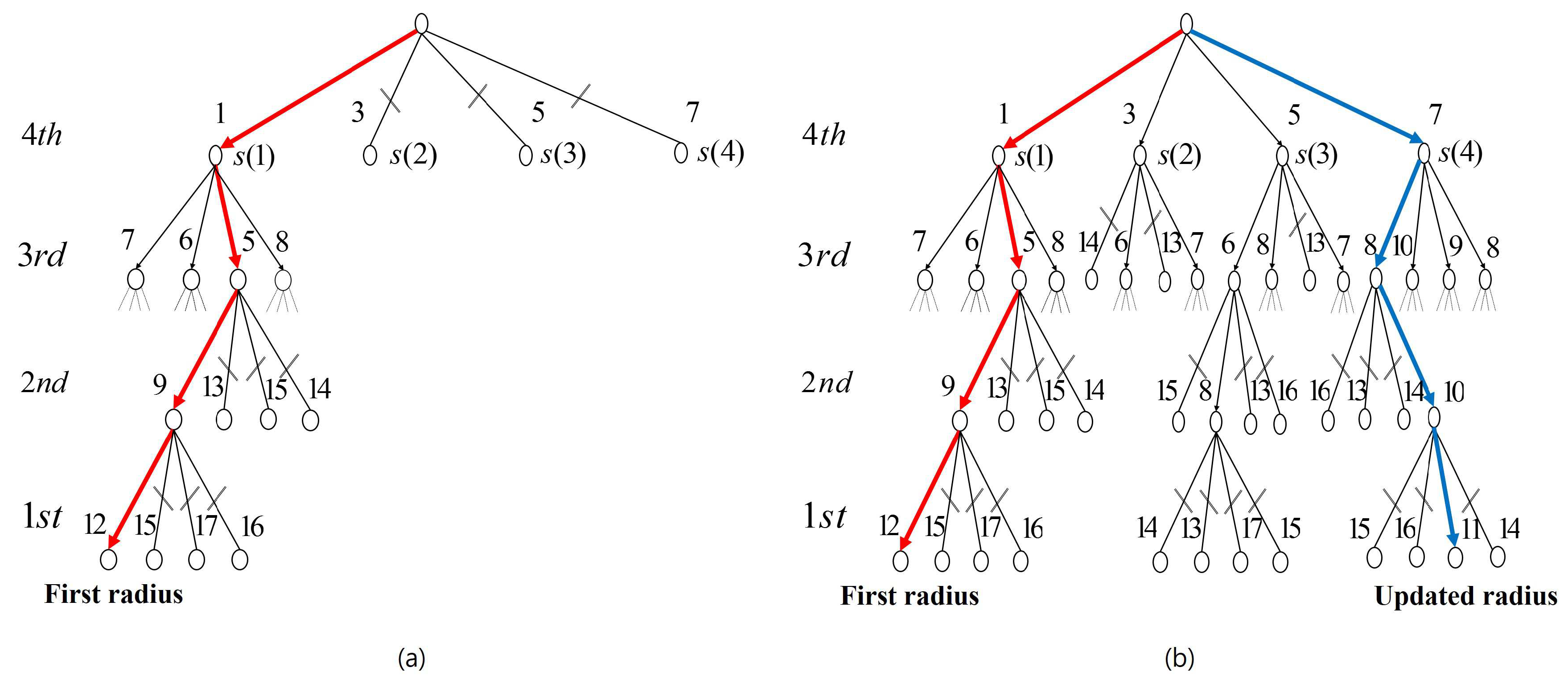
Figure 3 shows the overall adaptive DFSD tree structure in 4 × 4 MIMO-OFDM system with QPSK modulation. There are too many metrics to include in Figure 3, so several metrics are omitted through the dotted lines like in Figure 2. At the N t -th layer, the nodes are sorted according to ascending order of squared ED. The adaptive detection scheme uses an DFSD detection scheme with a different number of nodes in an ascending order of squared ED at the N t -th layer depending on the channel condition. Figure 3a shows the DFSD detection scheme using one node at the N t -th layer and Figure 3b shows the DFSD detection scheme using all nodes at the N t -th layer. A description of the DFSD detection scheme using two and three nodes at the N t -th layer is omitted. In Figure 3a, from Equation (10), the first radius distance is calculated as follows,
d 1 1 ( 1 ) = z 1 r 11 s ( 1 ) + r 12 x ^ 2 1 + r 13 x ^ 3 3 + r 14 x ^ 4 1 2 + d 2 3 ( 1 ) .
According to Figure 3a and Equation (11), the accumulated squared ED of the first radius is 12. Also, the path of the first radius includes the reference symbols of corresponding nodes. Transmit symbols are estimated through the reference symbols. On the other hand, in Figure 3b, the first radius distance is equal to that in Figure 3a. However, by updating the radius distance and pruning the path, Figure 3b shows the shortest accumulated squared ED as follows,
d 1 4 ( 3 ) = z 1 r 11 s ( 3 ) + r 12 x ^ 2 4 + r 13 x ^ 3 1 + r 14 x ^ 4 4 2 + d 2 1 ( 4 ) .
According to Figure 3b and Equation (12), the accumulated squared ED of the updated radius is 11. Finally, the path of the updated radius includes the reference symbols of corresponding nodes.
According to the Figure 3, Equations (11) and (12), the DFSD detection scheme using all nodes at the N t -th layer detects the signal more accurately than the DFSD detection scheme using one node at the N t -th layer. However, the DFSD detection scheme using all nodes at the N t -th layer passes through more nodes than the DFSD detection scheme using one node at the N t -th layer. So, when the channel has the best condition, the proposed detection scheme uses one node at the N t -th layer. On the other hand, when the channel has the worst condition, the proposed detection scheme uses all nodes at the N t -th layer.

4.2. The Thresholds Based on Channel Condition

The channel condition number is defined as follows,
Γ ( m ) σ max ( m ) σ min ( m ) ,
where Γ ( m ) is the condition number of subcarrier channel matrix, σ max ( m ) is maximum singular value, σ min ( m ) is minimum singular value, and m is the subcarrier index. The channel condition is determined by the condition number. When Γ ( m ) is close to one, it is the best channel condition but when Γ ( m ) is larger than one, it is the worst channel condition [18,19]. Through the above conditions, the complexity depends on thresholds,
θ i = m = 1 N 2 Γ ( m ) i M N
Equation (14) shows the process of determining thresholds through statistical analysis. M denotes the modulation order, i denotes the index of threshold, N is the number of subcarriers and the number of thresholds is M 1 . Since Γ ( m ) is different depending on the channel condition, the thresholds should be distributed evenly according to the number of i indexes based on minimum Γ ( m ) and maximum Γ ( m ) . For example, in QPSK modulation, θ 1 is present at a quarter of the all Γ ( m ) . Also, θ 2 is present at a half of the all Γ ( m ) , and θ 3 is present at three quarters of the all Γ ( m ) . It means that there are thresholds for each interval on the channel condition number. Therefore, the DFSD detection scheme, having a different number of nodes at the N t -th layer, is adaptively used when Γ ( m ) changes.
Figure 4 shows the relationship between the channel condition number and the thresholds in QPSK modulation. In the adaptive DFSD detection scheme, when Γ ( m ) is smaller than θ 1 , that channel has the best condition and uses one node at the N t -th layer. Then, the DFSD detection scheme is processed from the ( N t 1 ) -th layer to the last layer as shown in Figure 3a. When Γ ( m ) is between θ 1 and θ 2 , the channel has a worse condition than the former channel and uses two nodes at the N t -th layer. Then, the DFSD detection scheme is also processed from the ( N t 1 ) -th layer to the last layer. In this way, when Γ ( m ) is between θ 2 and θ 3 , the adaptive DFSD detection scheme uses three nodes at the N t -th layer. Finally, when Γ ( m ) is larger than θ 3 , the channel has the worst condition and uses all nodes at the N t -th layer as shown in Figure 3b. It means that the adaptive DFSD detection scheme uses a few number of nodes at the N t -th layer in a good channel condition to reduce the complexity. In contrast, the adaptive DFSD detection scheme uses a large number of nodes at the N t -th layer in a bad channel condition to improve the error performance.
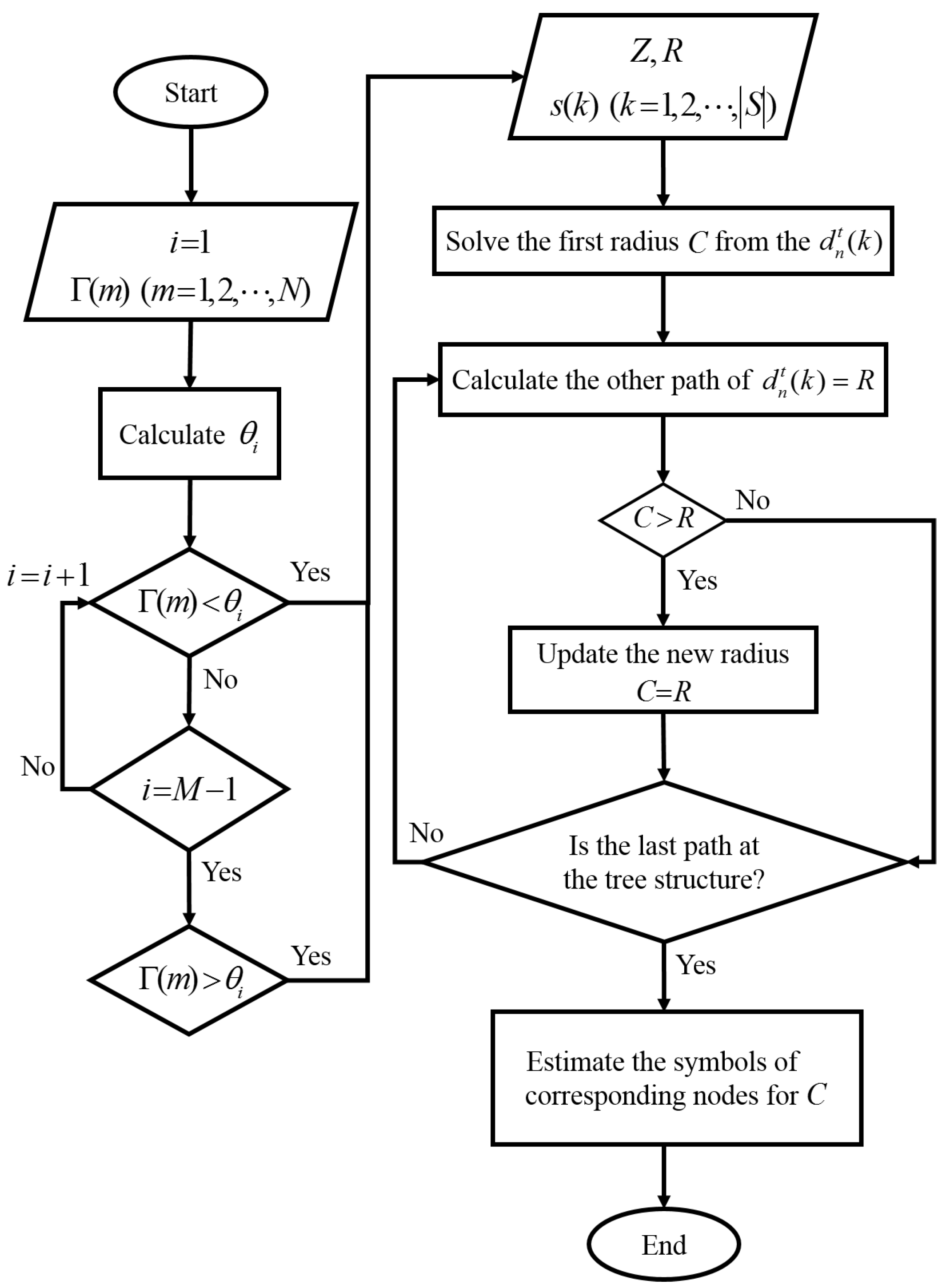
Figure 5 shows the flowchart for the adaptive DFSD detection scheme. The flowchart contains the method for determining the number of nodes at the N t -th layer and for reducing the path.

5. Simulation Results

Simulation results show the error performance and the complexity. As simulation parameters, the size of FFT was 128 and the size of CP was 32. Also, transmit symbols go through a Rayleigh fading channel with seven multi-paths and channels are modelled through the exponential power delay profile as follows,
P ( u ) = 1 P s u m e u P s u m ( u = 1 , , U ) ,
where P ( u ) is the element of exponential power delay profile, P s u m is the total exponential power delay profile, u is the index of multi-paths and U is the number of multi-paths. The simulation is conducted under the assumption that the MIMO channels are independent and identically distributed random variables. Also, the convolutional coding was used for the simulation to correct the error bits and to improve the BER performance. It consisted of the 2 × 2 and 4 × 4 MIMO-OFDM system with 16-quadrature amplitude modulation (QAM) and 64-QAM.

5.1. The Bit Error Rate Performance

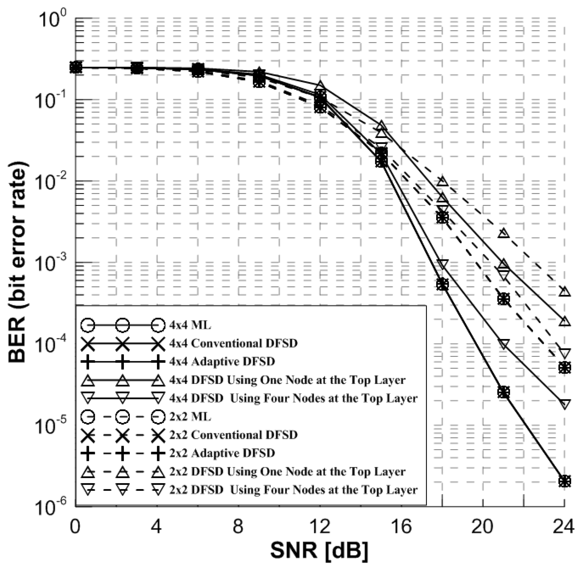
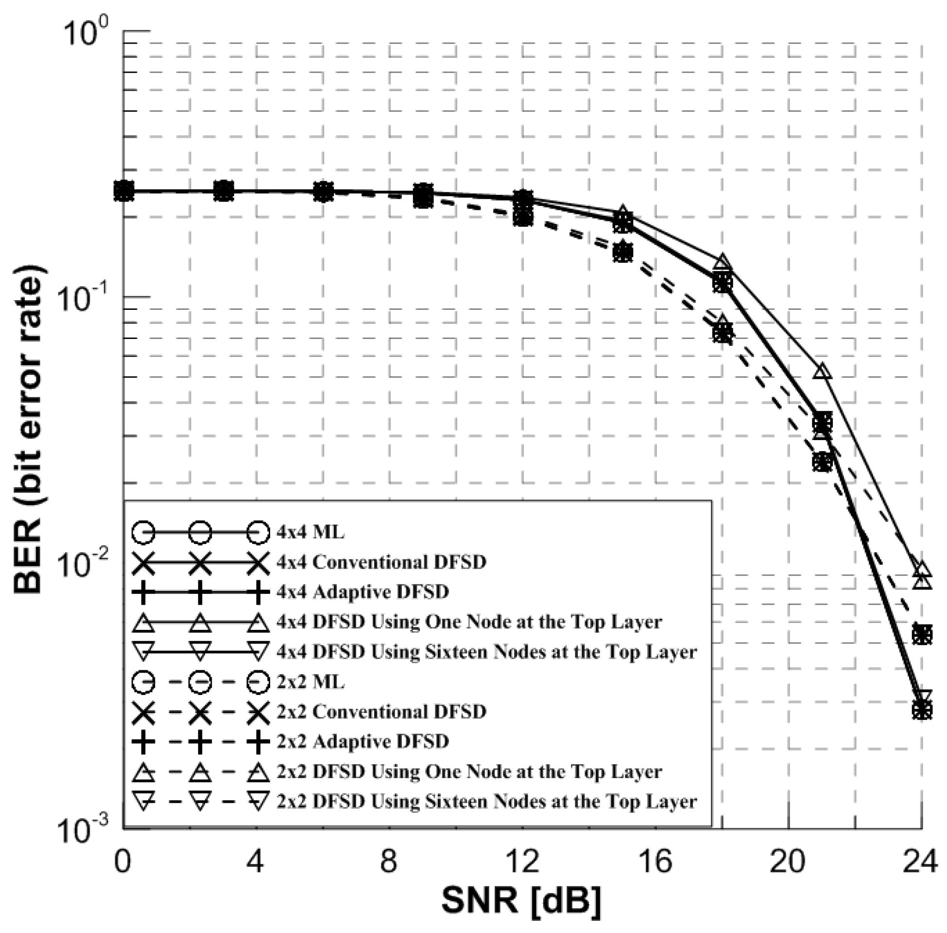
Figure 6 shows the error performance comparing the ML, conventional DFSD, adaptive DFSD and DFSD detection scheme using one and four nodes at the N t -th layer. Also, Figure 7 shows the error performance comparing the ML, conventional DFSD, adaptive DFSD and DFSD detection scheme using one and sixteen nodes at the N t -th layer.
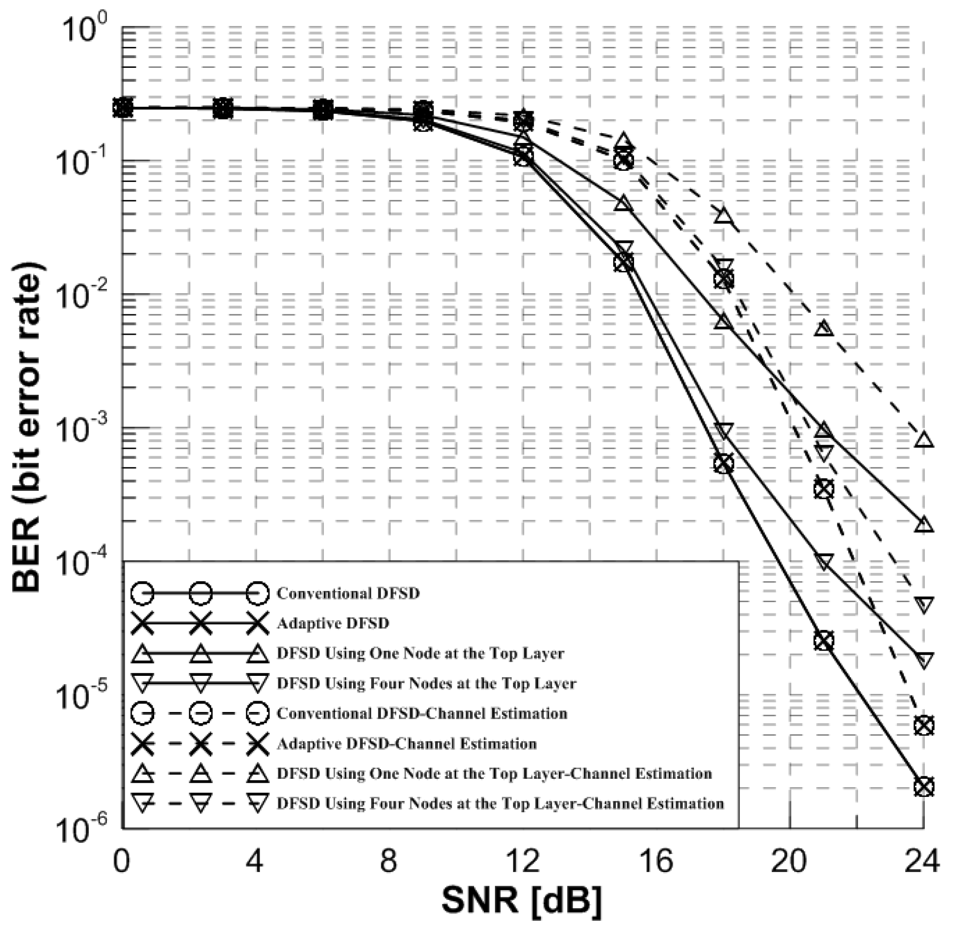
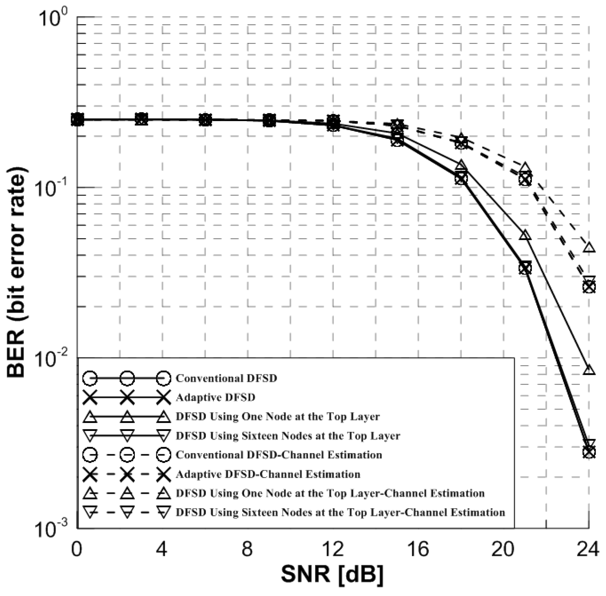
As a result of the error performance in Figure 6 and Figure 7, the adaptive DFSD detection scheme has similar error performance compared to the ML and the conventional DFSD detection scheme in the 2 × 2 and 4 × 4 MIMO-OFDM systems. Also, from the simulation results using the different modulation scheme in Figure 6 and Figure 7, it is shown that the adaptive DFSD detection scheme has suboptimal performance both 16-QAM and 64-QAM.
Additionally, Figure 6 shows the DFSD detection schemes using one and four nodes at the N t -th layer. Also, Figure 7 shows the DFSD detection schemes using one and sixteen nodes at the N t -th layer. These detection schemes have a worse error performance. Especially, the DFSD detection scheme using one node at the N t -th layer has the worst error performance among the DFSD detection schemes. So, the proposed detection scheme uses the DFSD detection scheme using one node at the N t -th layer when the channel has the best condition. On the other hand, when the channel has the worst condition, the conventional DFSD detection scheme is used. It means that all nodes are used at the N t -th layer for the worst conditioned channel. Through this process, the proposed DFSD detection scheme adaptively uses the different nodes of the N t -th layer depending on the channel condition.
Figure 8 and Figure 9 show the simulation results for the channel estimation [20]. It was assumed that channel estimation is perfect in the Figure 6 and Figure 7 and the least square (LS) channel estimation algorithm was used in Figure 8 and Figure 9. Each pilot symbol was transmitted every fourth OFDM symbol. As the simulation results show, although the detection schemes in the condition of the estimated channel using the pilot symbol have worse error performance than the condition of the completely estimated channel, the adaptive DFSD detection scheme has suboptimal error performance in the condition of the estimated channel.

5.2. The Complexity

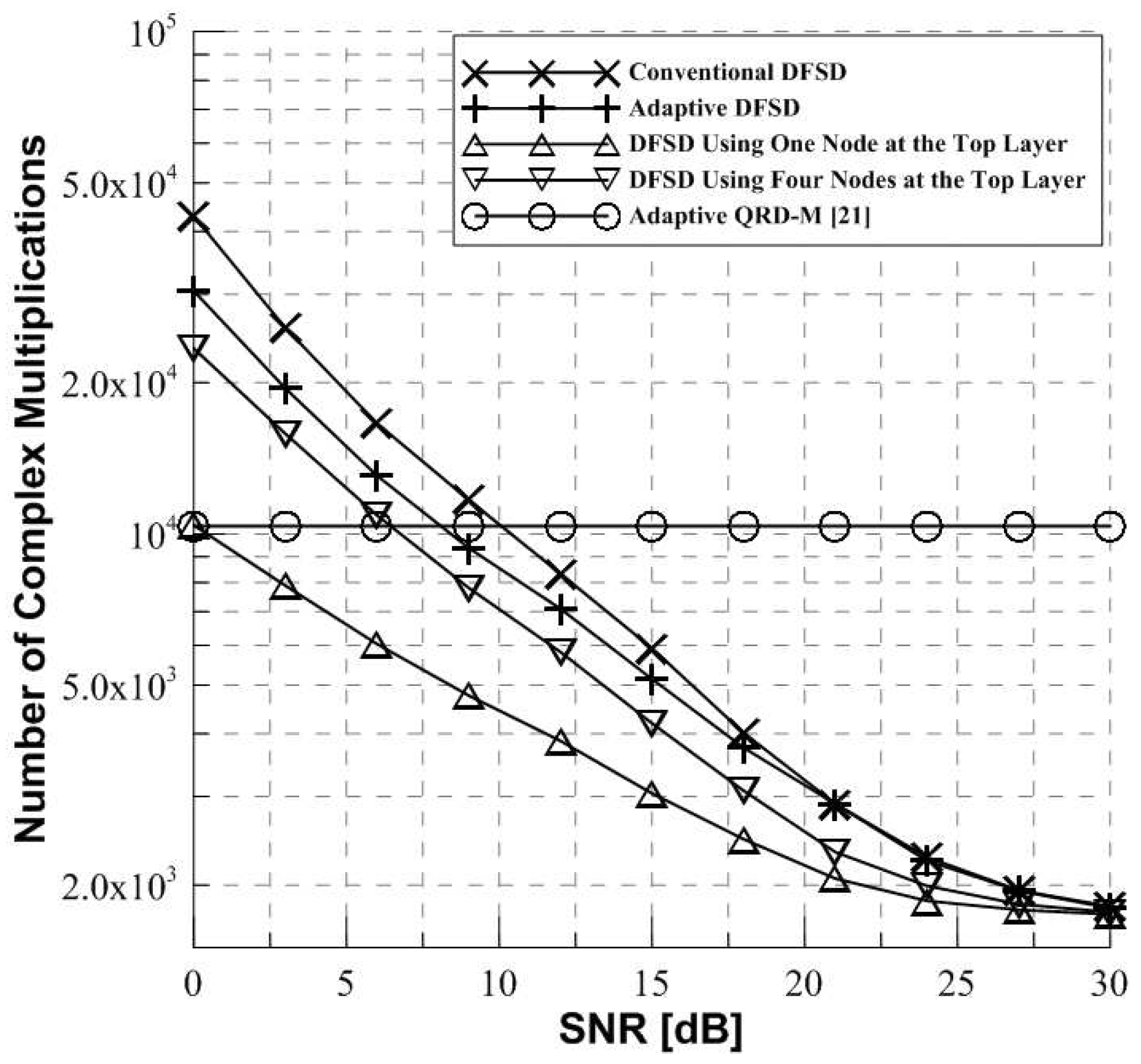
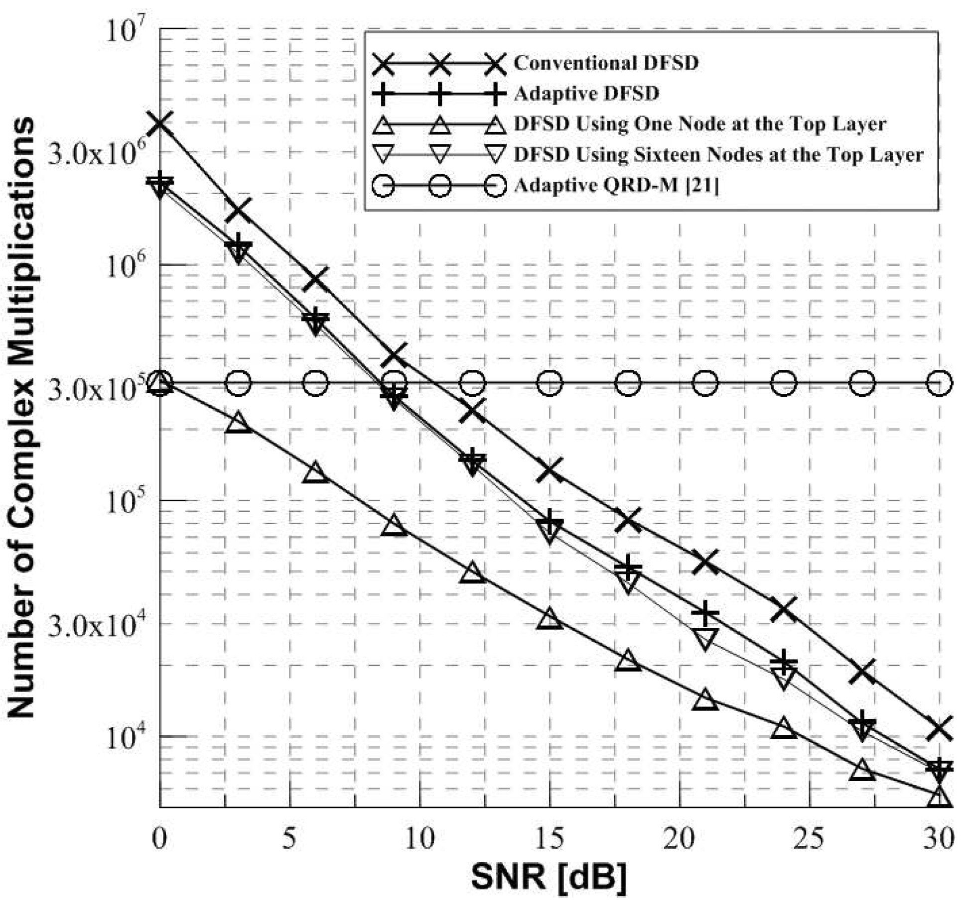
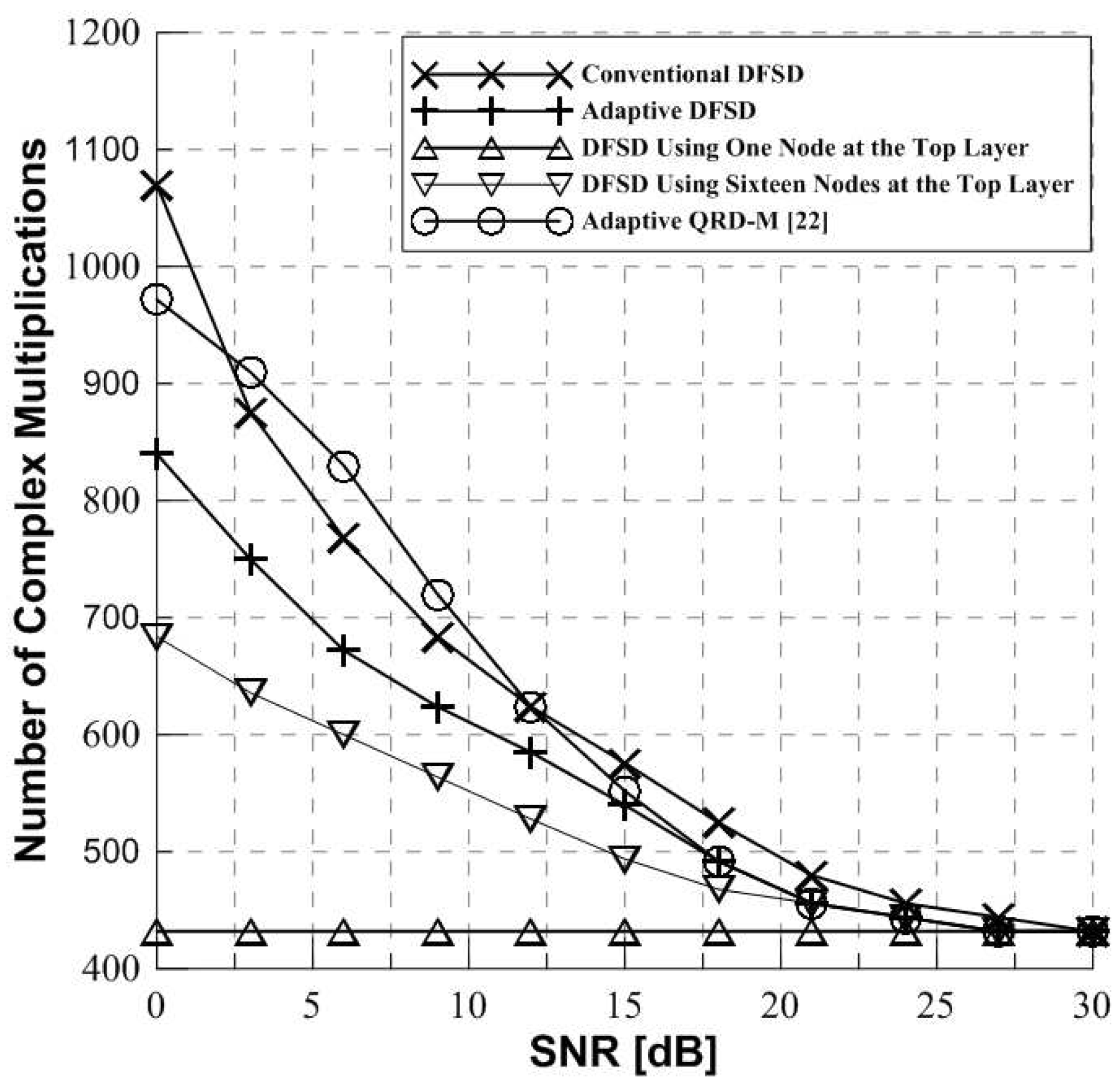
Figure 10 shows the complexity comparing the conventional DFSD, adaptive DFSD, DFSD detection scheme using one and four nodes at the N t -th layer and adaptive QR decomposition-M (QRD-M) [21] in the 4 × 4 MIMO-OFDM system with 16-QAM. Also, Figure 11 shows the complexity comparing the conventional DFSD, adaptive DFSD, DFSD detection scheme using one and sixteen nodes at the N t -th layer, and adaptive QRD-M [21] in 4 × 4 MIMO-OFDM system with 64-QAM. QRD-M is the non-linear detection algorithm. QRD-M detection scheme has suboptimal performance and lower complexity compared to the ML detection scheme. The complexity is defined as the number of complex multiplications required to obtain the received symbols at the tree structure. The complex multiplication expressions according to each detection scheme are shown in Table 1. The complex multiplication is calculated from the inverse channel matrix, process of the QR decomposition of channel matrix, multiplication of Y and Q H , and the number of nodes required per layer of tree structure. Especially, the adaptive DFSD detection scheme additionally computes the threshold based on channel condition.
It is shown in Figure 10 and Figure 11 that the DFSD detection schemes have lower complexity as the SNR increases. As the SNR increases, the influence of the noise and the initial radius becomes small, and then the complexity becomes low. Also, it can be generally seen that the proposed detection scheme has lower complexity than the conventional DFSD detection scheme. When the proposed detection scheme compares with the adaptive QRD-M [21], the proposed detection scheme has high complexity compared to the adaptive QRD-M [21] at less than 8dB of SNR. On the other hand, the proposed detection scheme has low complexity compared to the adaptive QRD-M [21] at more than 8dB of SNR. Because the adaptive QRD-M [21] has the fixed complexity. Although the proposed detection scheme has high complexity than the adaptive QRD-M [21] at low SNR, the proposed detection scheme has lower complexity than the conventional DFSD detection scheme at low SNR and lower complexity than the adaptive QRD-M [21] detection scheme at high SNR.
Figure 12 shows the complexity comparing the conventional DFSD, adaptive DFSD, DFSD detection scheme using one and four nodes at the N t -th layer and adpative QRD-M [22] in 2 × 2 MIMO-OFDM system with 16-QAM. It is shown that the proposed detection scheme has lower complexity than the adaptive QRD-M [22].
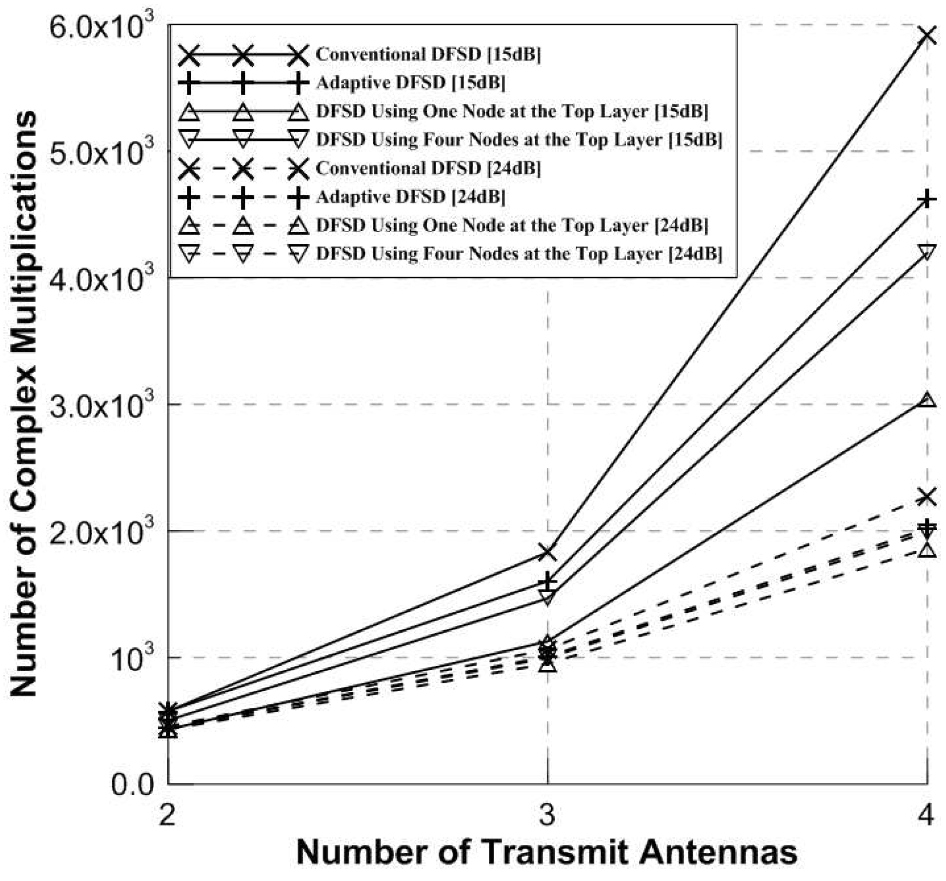
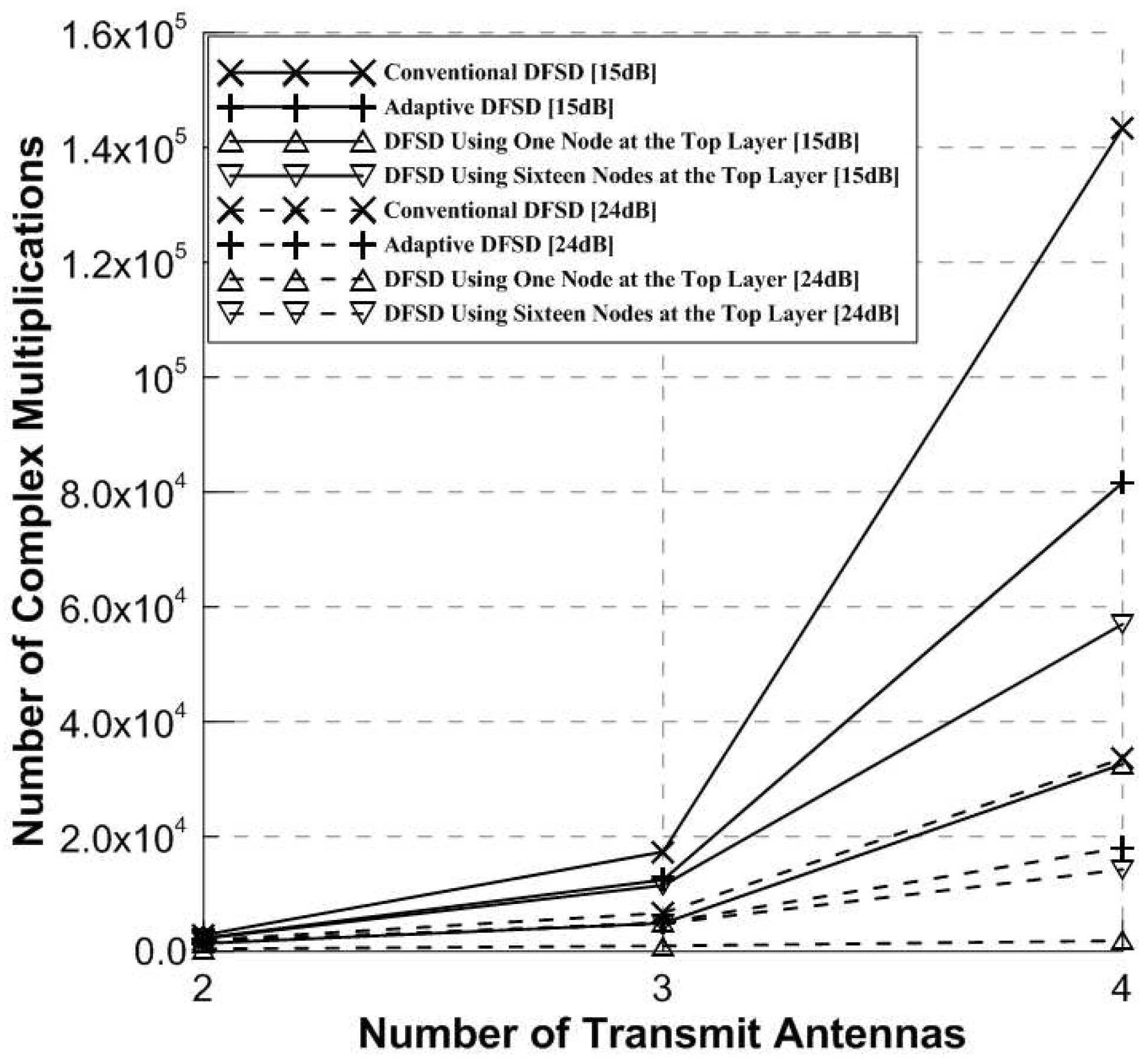
Figure 13 and Figure 14 show the complexity of the detection schemes according to number of transmit antennas and SNR with 16-QAM and 64-QAM respectively. Figure 13 and Figure 14 show the example when SNR is 15 dB and 24 dB. As a result of Figure 13 and Figure 14, the adaptive DFSD detection scheme has lower complexity than the conventional DFSD detection scheme. Also, as the number of transmit antennas increases, the increase rate of complexity for the adaptive DFSD detection scheme is lower than the increase rate of complexity for the conventional DFSD detection scheme. Especially, the increase rate of complexity for the adaptive DFSD detection scheme at the 24 dB of SNR is lower than the increase rate of complexity for the adaptive DFSD detection scheme at the 15 dB of SNR. Based on the above results, the adaptive DFSD detection scheme at low SNR has lower complexity and the lower increase rate of complexity according to the number of transmit antennas than the conventional DFSD detection scheme.

6. Conclusions

In this paper, the adaptive DFSD detection scheme is proposed in MIMO-OFDM system of wireless communication to reduce the power consumption. The proposed detection scheme uses thresholds based on channel conditions to vary the number of the N t -th layer nodes. At the N t -th layer, the nodes are sorted according to ascending order of squared ED. Then, the proposed detection scheme selects the number of nodes according to thresholds based on channel condition. Finally the DFSD detection scheme is processed from the ( N t 1 ) -th layer to the last layer.
It is shown that the proposed detection scheme is similar to the error performance of the ML detection scheme and the conventional DFSD detection scheme. Also, the proposed detection scheme has lower complexity and lower increase rate of complexity according to the number of transmit antennas than the conventional DFSD detection scheme. The proposed detection scheme has lower complexity compared to the adaptive QRD-M [21,22] detection schemes at the high SNR and all SNR ranges, respectively. Therefore, this proposed detection scheme is an efficient detection scheme to lower the power consumption by reducing the complexity.

Author Contributions

S.-J.S. proposed the adaptive DFSD detection scheme algorithm and processed the simulation; S.-J.C. analyzed the simulation results and made the figure; H.-K.S. reviewed the adaptive DFSD detection scheme algorithm and provided the experimental materials for better computational simulations and revised critical errors of the manuscript.

Acknowledgments

This research was supported by Institute for Information & communications Technology Promotion (IITP) grant funded by the Korea government (MSIT) (No. 2017-0-00217, Development of Immersive Signage Based on Variable Transparency and Multiple Layers) and was supported by the MSIT (Ministry of Science and ICT), Korea, under the ITRC (Information Technology Research Center) support program (IITP-2018-2018-0-01423) supervised by the IITP (Institute for Information & communications Technology Promotion).

Conflicts of Interest

The authors declare no conflict of interest.

References

  1. Paulraj, A.J.; Gore, D.A.; Nabar, R.U.; Bolcskei, H. An overview of MIMO communications-a key to gigabit wireless. Proc. IEEE 2004, 92, 198–218. [Google Scholar] [CrossRef]
  2. Foschini, G.J. Layered space-time architecture for wireless communication in a fading environment when using multi-element antennas. Bell Labs Tech. J. 1996, 1, 41–59. [Google Scholar] [CrossRef]
  3. Tarokh, V.; Seshadri, N.; Calderbank, A.R. Space-time codes for high data wireless communication: performance criterion and code construction. IEEE Trans. Inf. Theory 1998, 44, 744–765. [Google Scholar] [CrossRef]
  4. Jiang, Y.; Varanasi, M.K.; Li, J. Performance analysis of ZF and MMSE equalizers for MIMO systems: An in-depth study of the high SNR regime. IEEE Trans. Inf. Theory 2011, 57, 2008–2026. [Google Scholar] [CrossRef]
  5. Shao, X.; Yuan, J.; Shao, Y. Error performance analysis of linear zero forcing and MMSE precoders for MIMO broadcast channels. IET Commun. 2007, 1, 1067–1074. [Google Scholar] [CrossRef]
  6. Bei, W.; Zhu, Q. A low complex V-BLAST detection algorithm for MIMO-OFDM system. In Proceedings of the 4th International Conference on Wireless Communications, Networking and Mobile Computing, Dalian, China, 11–14 October 2008. [Google Scholar]
  7. Golden, G.D.; Foschini, C.J.; Valenzuela, R.A.; Wolniansky, P.W. Detection algorithm and initial laboratory results using V-BLAST space-time communication architecture Electron. Lett. 1999, 35, 14–16. [Google Scholar]
  8. Farhoodi, A.A.; Biguesh, M. ML detection in MIMO communication systems with imperfect channel knowledge. In Proceedings of the IEEE International Symposium on Signal Processing and Information Technology, Vancouver, BC, Canada, 27–30 August 2006. [Google Scholar]
  9. Zhu, X.; Murch, R.D. Performance analysis of maximum likelihood detection in a MIMO antenna system. IEEE Trans. Commun. 2002, 50, 187–191. [Google Scholar] [CrossRef]
  10. Viterbo, E.; Boutros, J. A universal lattice code decoder for fading channels. IEEE Trans. Inf. Theory 1999, 45, 1639–1642. [Google Scholar] [CrossRef]
  11. Li, S.P.; Wang, L.; Chen, F.C. Ordered sphere decoding detection algorithm for MIMO systems. In Proceedings of the 24th Chinese Control and Decision Conference, Taiyuan, China, 23–25 May 2012. [Google Scholar]
  12. Hassibi, B.; Vikalo, H. On the sphere-decoding algorithm I. Expected complexity. IEEE Trans. Signal Process. 2005, 53, 2806–2818. [Google Scholar] [CrossRef] [Green Version]
  13. Albreem, M.A.M.; Salleh, M.F.M. Lattice sphere decoding technique assisted optimum detection for block data transmission systems. In Proceedings of the International Conference on Cyber-Enabled Distributed Computing and Knowledge Discovery, Sanya, China, 10–12 October 2012. [Google Scholar]
  14. Barbero, L.G.; Thompson, J.S. Fixing the complexity of the sphere decoder for MIMO detection. IEEE Trans. Wirel. Commun. 2008, 7, 2131–2142. [Google Scholar] [CrossRef]
  15. Jang, H.; Nooshabadi, S.; Kim, K.; Lee, H.N. Circular Sphere Decoding: A Low Complexity Detection for MIMO Systems With General Two-dimensional Signal Constellations. IEEE Trans. Veh. Technol. 2017, 66, 2085–2098. [Google Scholar] [CrossRef]
  16. Wen, Y.; Wu, L. A modified sphere detection algorithm with lower complexity for MIMO detection. In Proceedings of the International Conference on Communication, Control, Computing and Electronics Engineering, Khartoum, Sudan, 16–18 January 2017. [Google Scholar]
  17. Rachid, M.; Daneshrad, B. A low-complexity iterative MIMO sphere decoding algorithm. In Proceedings of the 17th European Signal Processing Conference, Glasgow, UK, 24–28 August 2009. [Google Scholar]
  18. Choi, S.J.; Kim, J.K. Lattice-reduction aided signal detection method with switching detection based on channel condition. IEICE Trans. Fundam. Electron. Commun. Comput. Sci. 2017, E100-A, 2539–2542. [Google Scholar] [CrossRef]
  19. Maurer, J.; Matz, G.; Seethaler, D. Low-complexity and full-diversity MIMO detection based on condition number thresholding. In Proceedings of the IEEE International Conference on Acoustics, Speech and Signal Processing, Honolulu, HI, USA, 15–20 April 2007. [Google Scholar]
  20. Sutar, M.B.; Patil, V.S. LS and MMSE estimation with different fading channels for OFDM system. In Proceedings of the International Conference of Electronics, Communication and Aerospace Technology, Coimbatore, India, 20–22 April 2017. [Google Scholar]
  21. Yoo, H.; Jeong, J.; Lee, J. Signal position-based adaptive QR decompositionbased M detection algorithm for multiple-input multiple-output systems. IET Signal Proc. 2011, 5, 598–602. [Google Scholar] [CrossRef]
  22. Lim, H.; Park, G.; Yoon, D. Clipping method for adaptive QRD-M detection. In Proceedings of the International Conference on Information and Communication Technology Convergence, Jeju, Korea, 18–20 October 2017. [Google Scholar]
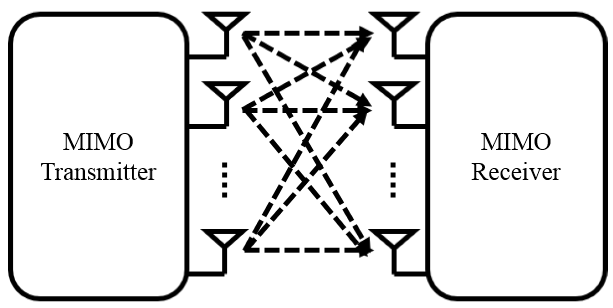
Figure 1. Multiple input and multiple output based on orthogonal frequency division multiplexing (MIMO-OFDM) system.
Energies 12 00599 g001
Figure 2. Depth-first sphere decoding (DFSD) tree structure in 4 × 4 MIMO-OFDM system with quadrature phase shift keying (QPSK) modulation.
Energies 12 00599 g002
Figure 3. Adaptive DFSD tree structure in 4 × 4 MIMO-OFDM system with QPSK modulation. (a) Proposed detection scheme in the best channel condition; (b) Proposed detection scheme in the worst channel condition.
Energies 12 00599 g003
Figure 4. The relationship between the channel condition number and the thresholds.
Energies 12 00599 g004
Figure 5. The flowchart for the proposed DFSD detection scheme.
Energies 12 00599 g005
Figure 6. The error performance of the detection schemes with 16-quadrature amplitude modulation (QAM).
Energies 12 00599 g006
Figure 7. The error performance of the detection schemes with 64-QAM.
Energies 12 00599 g007
Figure 8. The error performance of the detection schemes with 16-QAM at the estimated channel. SNR: signal-to-noise ratio; BER: bit error rate.
Energies 12 00599 g008
Figure 9. The error performance of the detection schemes with 64-QAM at the estimated channel.
Energies 12 00599 g009
Figure 10. The complexity of the detection schemes in 4 × 4 MIMO-OFDM system with 16-QAM.
Energies 12 00599 g010
Figure 11. The complexity of the detection schemes in 4 × 4 MIMO-OFDM system with 64-QAM.
Energies 12 00599 g011
Figure 12. The complexity of the detection schemes in 2 × 2 MIMO-OFDM system with 16-QAM.
Energies 12 00599 g012
Figure 13. The complexity of the detection schemes according to number of transmit antennas with 16-QAM.
Energies 12 00599 g013
Figure 14. The complexity of the detection schemes according to number of transmit antennas with 64-QAM.
Energies 12 00599 g014
Table 1. The complex multiplication expression according to detection schemes.
Detection SchemeComplex Multiplication Expression
Conventional DFSD 12 N t 3 + 4 N t 2 + 4 i = 1 N t L N t i + 1 ( i + 1 )
Adaptive DFSD 20 N t 3 + 4 N t 2 + 4 ( M 1 ) + 4 i = 1 N t L N t i + 1 ( i + 1 )
DFSD using n nodes at the top layer 12 N t 3 + 4 N t 2 + 4 i = 1 N t L N t i + 1 ( i + 1 )
Adaptive QRD-M 12 N t 3 + 4 N t 2 + 4 i = 1 N t L N t i + 1 ( i + 1 )
L i : the number of nodes at the i-th layer