Abstract
Fired equipment suffers from local overloading and fouling of heat transfer surfaces, products are not of the required quality, and operating costs are increased due to the high pressure drop of process fluids. Such operational issues are affected by the non-uniform distribution of fluid flow and heat flux variability. Detailed numerical analyses are often applied to troubleshoot these problems. However, is this common practice effective? Is it not better to prevent problems from occurring by using quality equipment design? It is, according to the general consensus. Still, the experience of designing fired apparatuses reveals that the established standards do not reflect the real maldistribution sufficiently. In addition, as found from the given overview of modelling approaches, the radiant chamber and the convection section are usually analysed separately without significant continuity. A comprehensive framework is hence introduced. The proposed procedure clearly defines the interconnection of traditional thermal-hydraulic calculations and low-cost modelling systems for radiant and convection sections. A suitable combination of simplified methods allows for the reliable design of complex equipment and fast identification of problematic areas. The utilisation of selected low-cost models, i.e., the second phase of the systematic framework, is presented regarding the example of a steam boiler.
1. Introduction
Hot utilities are the most energy-consuming and therefore the costlier apparatuses in any industrial plant. Tubular fired heaters (cylindrical and cabin type) are distinctive components of petrochemical plants, continuous furnaces are used in metal processing, and boilers produce superheated steam for process and power purposes. Recently, waste-to-energy applications have become increasingly important and the waste incinerator furnace is their key component. All these processes and power apparatuses share two main features, i.e., the arrangement and the insufficient reliability of equipment design or operation, especially in the context of strict emission limits and pressure to achieve a greater efficiency.
Despite many similarities, boilers and furnaces tend to be described by different computation models, which are employed to design the major parts: the radiant and convection sections. A limiting factor of design procedures is the lack of necessary information. Since experiments can be carried out on the fired equipment in only a very limited scale, simplified (low-cost) modelling methods and numerical analyses based on computational fluid dynamics (CFD) have an irreplaceable role in the designing process. Furthermore, the apparatus is usually not equipped with a sufficient number of measuring devices for the purpose of examining the thermal and flow behaviour [1]. While basic measurement and control devices ensure safe operation, the collected data serves only as support information for the validation of simplified or numerical models.
In this article, we want to show that it is possible to improve the efficiency of the design procedure and increase the reliability of furnaces and boilers via a comprehensive computational methodology using up-to-date, low-cost models. Of course, this approach relies not only on accurate and fast individual models but also on their precise interconnection. Hence, the main objective of this work is to introduce the unifying framework that will link calculations of the radiant and convection sections. The chief motivation, i.e., the operational problems of fired equipment and current unsystematic (inefficient) approaches to modelling, is outlined in the first two parts of this paper. The description of the novel, low-cost modelling framework follows. The last part is devoted to a case study of a steam boiler. Through this practical application of the proposed framework, the selected low-cost modelling systems are discussed in detail.
Fired Equipment and Maldistribution Issues
Industrial boilers and fired heaters (see Figure 1) consist of two parts, a radiant section (also called radiant or combustion chamber) and a convection section. The shape of the radiant chamber and the configuration of heat transfer surfaces are designed depending on the required heat duty and the properties of the process fluids and fuel (problematic ones are mainly fouling propensity and heat sensitivity). The entire apparatus is then tailor-made to the specific application [2].
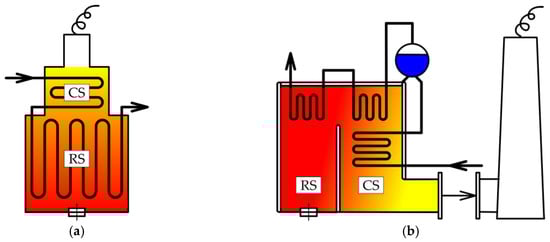
Figure 1.
Simplified schematic (a) of a cylindrical fired heater, and (b) of a two-pass boiler. Abbreviations CS and RS stand for convection and radiant sections, respectively.
In view of transferred heat, the dominant part of the equipment is the combustion chamber where the prevailing mechanism of heat transfer is radiation. Additionally, the heat transfer is the most intense in this part of the apparatus. Convective heat transfer predominates in the heat exchanger zone that follows. The heat transfer in this section may be enhanced to improve operational efficiency. The enhanced heat exchanger is even more sensitive to any non-uniformity of fluid flow than conventional equipment with plain tubes. Therefore, enhancements, e.g., tube fins, must be utilised only with regard to the flue gas temperature level and tendency to foul [3].
The exchanger section of a water-tube steam boiler possesses three parts:
- an economizer—serves to heat feed water, it is usually situated in areas with a lower flue gas temperature;
- an evaporator—tube-side fluid changes phase in this heat exchanger, which is often integrated into the membrane walls of the radiant and convection sections;
- a superheater—production of superheated steam that is used for a particular process or power application is finalised in this heat exchanger. It usually forms the first heat transfer surface in the convection section, but it is frequently installed above the radiant chamber.
For the reliable design of both parts of fired equipment (radiant and convection sections), it is necessary to identify the distribution of heat flux and process fluids. Recognition of heat flux variability crucially affects the faultless performance and service life of a tubular system in a radiant chamber. Design of the radiant chamber in fired heaters is based on established procedures, such as American Petroleum Institute (API) Standard 530 [4] and API Standard 560 [5]. Nevertheless, their calculation methods inadequately predict the longitudinal and circumferential maldistribution of heat flux. An assumption of average radiant heat flux and the neglecting of the burner’s actual thermal profile contributes to a decrease in efficiency and increased wear of the whole equipment or of some of its parts. Underestimation of this issue often causes serious operational problems of fired heaters: increased fouling of the tubular system (e.g., deposition of coke), overheating of the tube material with subsequent deformation and a dramatically increased pressure drop. In the worst-case scenario, an accident may happen [6], and in a better case, only unplanned shutdown procedure is activated, followed by cleaning and minor repairs [7].
Significant inaccuracies of the common design practice are particularly related to the recent use of low-NOx and ultralow-NOx burners. If these burners are compared with conventional burner types, thermal behaviour (flame length and width) is noticeably different [8]. Consequently, the peak thermal loading of the radiant heat transfer surfaces greatly varies [9].
The distribution of the flue gas flow, as the hot stream, is also essential in the convection section of the fired equipment. Typically, the heat exchangers contain dense tube bundles, which on the one hand increase the heat transfer, and on the other hand, complex geometry is more prone to the non-uniformity of the tube-side fluid flow [10]. The problematic flow behaviour in the tubes causes uneven loading of the heat transfer surfaces, especially when it is negatively influenced by flue gas maldistribution. An example of such a problematic area may be the turning position between the first and second pass of the steam boiler illustrated in Figure 1b.
The consequences of the described underestimation or negligence in the design procedure are addressed by equipment troubleshooting [11]. Of course, operational issues cannot be completely eliminated, but the goal of reliable design is to reduce the number and severity of problems as much as possible. An important feature of the suggested framework is the minimization of the potential operational difficulties thanks to taking the heat and fluid flow distribution into account as early as the initial phase of the design procedure. The use of the low-cost models for initial design calculations allows for fast identification of problem areas. In the next phase, a detailed but time-consuming CFD simulation can effectively analyse these bottlenecks.
2. Overview of the Modelling Approaches
In general, an increasingly prevalent trend in modelling different parts of an apparatus is the use of CFD simulations. It is the most flexible yet at the same time the most demanding approach. If the final stage of the new equipment design is to be solved or if problems of the already operating units are being investigated, the use of numerical models is undoubtedly beneficial. According to the broad overview provided by Aslam Bhutta et al. [12], the CFD thermal analyses of different heat exchangers can achieve an agreement with measured data within 5 %. The high accuracy of the results compensates for the long process of preparation and computation itself. The long time required to obtain results, of course, increases the cost of these analyses.
The basic challenges of CFD modelling involve the creation of a high-quality mesh whose size should be as small as possible [13]. In order to determine a suitable number of elements, a grid independence test is carried out. As an example, analyses of distribution systems [14] can be mentioned. Gandhi et al. [14] tested meshes consisting of hexahedral and tetrahedral elements. A similar flow geometry (with a slightly higher number of tubes) was also investigated by Zhou et al. [15] who used relatively new polyhedral cells in combination with prismatic elements. Regarding the flow system including only 14 tubes and 2 headers, the grid independence test [15] indicated that the optimal mesh should contain almost three million cells. It should be noted that these two studies did not examine heat transfer, and moreover, the maximum number of tubes was only 50 [14] and 70 [15]. In practice, heat transfer apparatuses with much larger tube bundles are employed. Typical representatives of such equipment are, for example, heat exchangers in boilers and heat recovery steam generators (HRSGs). It is apparent that the thermal analyses of large distribution systems tend to be computationally intensive and highly time-consuming. Various approaches that balance accurate data and the computing costs of CFD models will be described as follows.
Poursaeidi and Arablu [16] combined two-dimensional (2D) CFD models with three-dimensional (3D) models of one pass of a steam boiler to address both combustion and non-uniform steam distribution. First, the 2D models evaluate the division of flow in manifolds. One tube in a simplified 2D geometry stands for a row with ten tubes in real conditions [16]. Then, a 3D combustion model yields temperature fields in the combustion chamber. Finally, the boiler is divided into simpler heat exchangers. In these parts, heat transfer is analysed using 3D CFD models, which employ the results obtained previously. The combination of 3D and 2D CFD simulations was also used for analysing heat transfer in a vertical fired heater [17]. In this case, the 3D model provides an insight into the longitudinal distribution of the heat flux in the combustion chamber. The 2D models then specify the effect of geometrical imperfections on the circumferential heat flux variability.
The model described by Gómez et al. [1] calculates thermal fields on the sides of both fluids (flue gas and steam), as well as the tube wall temperature, and the shell-side flow-field in the convection section of a boiler in the power industry. This model employs the special types of elements that substitute tubes (so-called sub-grid features) and headers (virtual elements). Via modelling the entire structures that are similar in their geometry, physical properties and topology, rather than meshing the individual tubes, it is possible to significantly reduce the size of the mesh. The major advantage of this model is the interconnection of the tube banks in the convection section, which improves the accuracy of the obtained results.
Models with individual HRSG tubes were compared by Galindo-García et al. [18] with models that replaced tube bundles with porous layers. In order to decrease the number of cells, Galindo-García et al. [18] relied on a non-conformal mesh, with individual parts of HRSG being linked by an interface. Additional shortening of evaluation time brings a steady state simulation. Another example of the use of the porous layer is the work of Naď et al. [19], who focused on flue gas flow in an industrial boiler. Replacement of tube bundles with larger (porous) zones is advantageous for the evaluation of flow in the shell, but this technique causes loss of information about the local thermal loading of heat transfer surfaces. From this point of view, Gómez et al. [1] offered the most comprehensive approach, which can be modified so that, according to its authors, it can assume the non-uniform distribution of the fluid in tubes.
Most authors use various versions of a commercial software Ansys Fluent, except for, e.g., Zhou et al. [15] (Siemens’ STAR-CCM+) and Manickam et al. [20]. The last-mentioned authors [20] solved a waste heat recovery boiler problem using the software CFD-FLOW3D (now provided by Ansys as a software tool CFX).
Taking into account the before-mentioned cases, it is clear that the use of CFD in an initial design phase is rather ineffective. Contrarily, in the initial phase, it is necessary to quickly exclude completely inappropriate configurations, adjust the main dimensions and select the most suitable configuration for further detailed calculations. For the purpose of this sizing procedure, the simplified (i.e., low-cost) models and methods that will be described as follows fit much better.
Considering the convection section, the models of heat exchangers can be classified into three categories. The first category of models focuses on the distribution of the working fluids while heat transfer (convection) is neglected. For the second group, the calculations concentrate on heat transfer whilst flow distribution is always supposed to be known and usually also to be uniform (see, e.g., Lan et al. [21]). If needed, the potentially non-uniform distribution of fluid flow must be estimated by another calculation tool. This is the case, for example, for the cell method [22] or a cross flow calculation presented by Shah and Sekulić [23]. Models that capture both phenomena in a simplified manner represent the last category.
The first group includes fast isothermal models [24,25], which predict the flow rates and pressures in dividing flow manifolds. The model [24] describes the distribution systems in differential form. These equations are elegant but depend on a knowledge of actual velocity profiles in tube inlet ducts. More practical is a formulation of correction coefficients that was used in the work [25]. Here, the coefficients (the coefficient of static pressure regain and discharge coefficient) are calculated using upstream and downstream values of respective variables.
The non-uniform heating of the water–steam mixture at different levels of the distribution system was analysed by Ngoma and Godard [26]. Unlike the previous models, this parallel system contained only one row of tubes. The results revealed that in the case of non-uniform thermal loading, the process fluid flow was slightly more uniformly distributed. A similar effect of (non-uniform) heating on the flow of refrigerant was observed by Cho et al. [27] when the fluid was heated in the last third of the microchannels. The opposite effect had local heating applied in only one of the nine sections of the distribution system [27]. It caused intense evaporation of the refrigerant, which resulted in a significant reduction in the mass flow rates in the respective channels.
If maldistribution in microchannels is taken into consideration, Baek et al. [28] reported an interesting comparison of effectiveness-NTU (i.e., number of transfer units) expressions. The obtained results showed that the linear maldistribution of a hot stream in the vertical direction had a particularly negative effect on the heat exchanger effectiveness. This one-dimensional (1D) model [28] analyses the pure countercurrent configuration of the heat exchanger, which in most industrial applications is just the ideal we are trying to converge toward.
A more accurate description is offered by models and relationships that deal with crossflow exchangers. This type of flow arrangement can be further sub-divided into pure crossflow, multi-pass parallel crossflow, and multi-pass counter-crossflow as shown in Figure 2. Multi-pass crossflow exchangers with different configurations are the objectives of, e.g., Cabezas-Gómez et al. [29], who discussed the applicability of the effectiveness-NTU simplified equations. Cabezas-Gómez et al. [29] point out that heat exchangers with more than six rows (or passes in terms of our work) should not be evaluated on effectiveness by simple expressions for the purely concurrent or purely countercurrent arrangement. There is a grey area where the theoretical relationships considering the number of tubes is no longer appropriate, yet the before-mentioned substitution cannot be made either. This situation arises if the number of passes is higher than four and lower than approx. 20 and 50 in the cases of parallel and countercurrent cross exchangers, respectively.
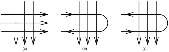
Figure 2.
Schematics illustrating different types of a cross flow arrangement: (a) pure crossflow, (b) two-pass parallel crossflow, and (c) two-pass counter-crossflow
Another unacceptable simplification that occurs in the models of multi-pass distribution systems is the creation of virtual mixing chambers at the turning points. This interconnection of the discretised parts of the heat exchanger (different types of flow geometries are sketched out, e.g., by Pignotti and Shah [30]) is frequently adopted by commercial software. The computational tools average the values of fluid properties in these virtual mixing chambers, unrealistically affecting the obtained temperature field, as well as the calculated thermal loading of the heat transfer surfaces.
As previously mentioned, calculations of fired equipment must adhere to the design standards. The design calculations of the furnace and boiler radiant section are based on the well-stirred furnace (WSF) model [31]. This model for determining radiant heat transferred to a radiant tubular system divides the furnace (or radiant chamber in general) into three zones representing the radiating flue gas, tubular system, and refractory walls. The 1D model [31] has a large number of simplifications (see, for instance, the comparison of this model with numerical simulations [32]); nevertheless it forms the basis for 2D thermal analyses in radiant section. The WSF model is still used in computational tools, for example, to optimize operating conditions [33] or to predict the fouling rate of crude oil [34].
Weaknesses of the WSF model (especially the strong underestimation of real heat flux distribution) are particularly evident in apparatuses with a significant temperature gradient due to the large difference between the two main dimensions. An example of such constructions is a cylindrical radiant chamber with its large height (or length) and relatively small diameter. The (long) radiant section of the total length L can be discretized into a series of segments of length dx. Heat transfer is then sequentially solved in each segment using a 1D plug-flow (PF) model (see, e.g., Hewitt et al. [35]). This model is sometimes called a long furnace model and can be applied in, e.g., the technical-economic analysis of possible energy savings [36]. The PF model requires the local volumetric heat release rate as a function of furnace length. If the flame is parallel to the furnace axis, the local volumetric heat release rate can be determined using an experiment or via a CFD simulation. Both ways are far from trivial. The disadvantages of the PF model were summarized by Jegla in his work [37]. Instead, he introduced a modified plug-flow (MPF) model. One of the improvements—the inclusion of the burner test results not only in the validation of the MPF model [38], but also in the calculation algorithm itself [8]—allows this model to accurately predict the distribution of heat flux in the radiant chamber.
The basic MPF model provides excellent results for cylindrical equipment with one burner, i.e., the equipment that is similar to the test combustion chamber [8]. Industrial fired equipment, however, usually contains more burners and the radiant section can have a rectangular cross-section (such as cabin furnaces), as well as the standard circular cross-section. The presence of multiple burners affects the flue gas flow (its mixing) and the overall character of the heat transfer in the radiant section. The cylindrical shape of a furnace is more favourable for the (uniformly) distributed heat and fluid flow than the cabin type [17]. These parameters are considered by the adapted modified plug-flow (hereafter AMPF) model, which was introduced by Jegla [7]. Of the models describing the design of the radiant chambers, the AMPF model is the most complex but also the most versatile low-cost technique.
On the one hand, simplified methods have, by their very nature, a good deal of limitations that the user must pay attention to. However, on the other hand, this modelling approach has a significant advantage in low computational requirements. This is the main reason for their use in design calculations. Moreover, some restrictions can be eliminated by using a suitable combination of models, as shown, for example, in the before-mentioned works [7,10]. If several simplified models (or different ways of estimation) are systematically linked, it is even possible to analyse the entire complex equipment possessing radiant and convection sections.
3. Proposed Calculation Framework
The common practice of designing fired equipment suffers from the inaccuracy of the employed empirical approximation. Therefore, the basic calculations of the established design standards are variously supplemented by the low-cost tools for modelling radiant and convection sections or these parts are being analysed in detail by CFD. In spite of the apparent interconnection of both parts, modelling activities are predominantly conducted separately. This may not be an issue if only one part of the apparatus is of interest. However, in the case of designing or rating the entire equipment, such a procedure is not systematic, and it also reduces the quality of the complete equipment design. Based on long-term experience with the design of fired equipment for process and power industries, there has been a need for a comprehensive methodology that would improve the reliability of the current design practice.
The aim of this work is to introduce such a framework that aggregates the basic thermal-hydraulic calculations of the radiant and convection section and fast and accurate low-cost computational models. Because of this systematic combination, the novel framework significantly increases the reliability of the fired equipment design. The calculation framework primarily serves the initial design of combustion equipment; however, it can be utilised for the thermal rating analysis of existing equipment.
The outline of the proposed approach is in Figure 3. In essence, this calculation procedure has two phases. In the first phase, standard thermal-hydraulic calculations are employed to obtain initial data on:
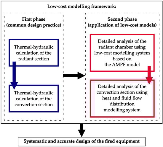
Figure 3.
Proposed systematic framework of the novel design procedure showing the interconnection between all calculations
- a radiant section—i.e., to evaluate the amount of radiant heat duty, the main dimensions of the radiant chamber and the tubular system;
- a convection section—among other things, to design the main parameters of tubular heat exchangers (number of tubes, tube geometry, etc.), average input, output temperatures and heat duty.
The second phase of the calculation procedure serves as the thorough investigation into the thermal-hydraulic behaviour of the respective equipment. It includes the analyses of heat and fluid flow maldistribution in the radiant and convection sections. The idea is to avoid CFD simulations as much as possible, despite the fact that they provide a very good insight into the heat transfer system. The considerable disadvantage of the CFD approach is its inability to flexibly respond to any modifications of the equipment dimensions that are often in the initial phase of the design procedure [38].
For the design of the radiant chamber, a low-cost modelling system using the AMPF model [7] is chosen. This universal three-step method takes into account the real local thermal load of the radiant tubular system. At first, the burner heat flux profile is experimentally determined. Then, the MPF model, which uses the results of the previous tests, is applied to identify the fuel burnt profile. In the last step, the design of the combustion chamber is completed using the AMPF model.
Information about flue gas distribution is subsequently taken over by another simplified modelling system for the exposed parts of the convection section. The heat and fluid flow distribution modelling system, which was presented by Jegla and Fialová [10], identifies locations that are potentially risky in view of thermal loading (overheating but also subcooling).
Both separate modelling systems are situated in the context of designing the complete fired equipment in order that the framework allows a continuous segue between the individual parts of the calculation. Such a homogeneous design of the complex fired equipment thus maintains a high degree of accuracy.
In the following part, the application of the calculation framework will be demonstrated, as well as a more detailed description of the utilised modelling systems, using an industrial example.
4. Case Study
The purpose of this section is to discuss the principles of the selected low-cost models in detail and to apply them to a case study of the steam boiler. In other words, the case study focuses on the second part of the suggested framework. First of all, the equipment in question will be described. The other two parts will be devoted to the modelling methods for the calculation of the heat flux distribution in the boiler radiant chamber and for the calculation of the temperature profile in the steam superheater.
At this point, it is necessary to point out that the case study did not deal with grassroots design, but with the equipment being operated. However, the use of low-cost models was the same as in the case of new designs. Since this was the investigation into the operated apparatus, the conclusions of both low-cost modelling systems were only of a recommending nature. Model results only indicated problematic locations or suggest their more appropriate configuration. Appropriate design modifications that would lead to the elimination of operational problems were not included in the case study. Also, the proposed framework did not contain a technical-economic analysis that would certainly precede the possible retrofit.
4.1. Industrial Boiler
The objective of the case study was a three-pass steam boiler with natural circulation (a schematic of the respective boiler will be shown in following subsection). The combustion chamber had a rectangular cross-section, measuring 5 × 7.2 m, and a total height of 18.4 m. At the heights of 7.5 m and 10 m, there were four burners, which enabled the combustion of liquid fuels (heavy fuel oil mixed with liquid tar waste) and natural gas. The boiler employed membrane walls with tubes of diameter 57 mm and steel strips 75 mm in width. This inbuilt tubular system served as an evaporator and cooled all walls of the combustion chamber and the second pass of the boiler (already a convection section). A total heat transfer area that ensured the production of saturated steam was 550 m2. The first heat exchanger area in the convection section was a final steam superheater. At the output of this heat exchanger, superheated steam had the following parameters: a temperature of approx. 370 °C and a mass flow of 16.7 kg/s. Downstream of the final superheater was a primary superheater. Economizers were located at the bottom of the second boiler pass and in the third pass.
Due to the previous operational problems, the whole boiler had undergone a non-destructive examination. The photograph in Figure 4 was taken during this inspection. The main overloaded heat transfer surface was identified in tubes of the final steam superheater, especially in the area before entering the collector. This was manifested as an increased material loss of these tubes. The general CFD simulation [19], which was utilised for the necessary troubleshooting, revealed that wall-thinning was induced by the non-uniform distribution of flue gas. The critical location was between the radiant chamber and the convection section where flue gas flow changed its direction. Therefore, the low-cost modelling system [10] was applied to a detailed analysis of the final steam superheater. The main topological and geometrical parameters of the heat exchanger, as well as the relevant properties of both fluids, are arranged in Table 1.
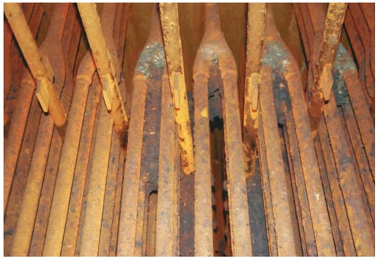
Figure 4.
Tube bundle of the final steam superheater; an orange colouration is a distinctive feature of the accumulated corrosion layer. Grey and black deposits of flue gas components are highly visible between tubes.

Table 1.
General parameters of the final steam superheater.
4.2. Low-Cost Modelling of the Radiant Section
As mentioned earlier in this paper, the MPF model [8] is sufficient only for single-burner cylindrical equipment without an inbuilt tubular heat transfer system. In contrast, the AMPF model [7] considers: (i) tube coils or membrane walls; and (ii) the rectangular, as well as circular, cross-section of a combustion chamber. Both models demonstrated extremely good accuracy regarding the modelled heat flux distribution in the radiant section. On the one hand, the low-cost AMPF model can design the industrial equipment respecting the real heat flux variability. On the other hand, the AMPF model requires information on the thermal characteristic of a burner in a suitable form, which can be provided by the MPF model. Therefore, the complete modelling procedure contained three steps, as shown in Figure 5.
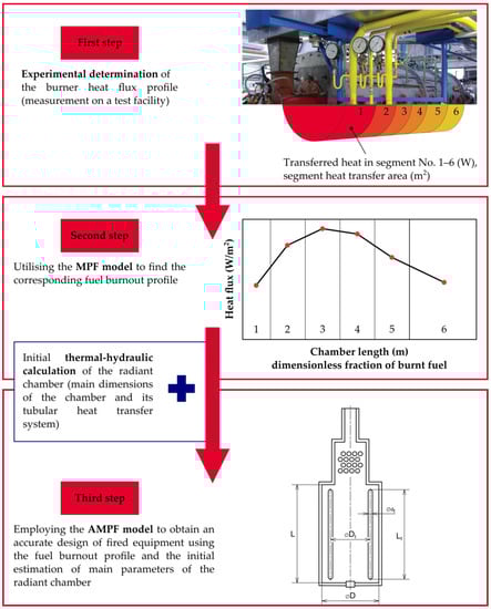
Figure 5.
Schematic flow chart of the three-step modelling system for an accurate and reliable design of fired equipment
The first step was determining the thermal characteristic of the burner, either the intended one (in case of brand-new designs or retrofit applications), or the one already installed (if rating calculations are needed). Of course, in situ measurements or the usage of a test facility was the most expensive approach as it necessitated not only specialised measurement equipment but also trained and experienced staff. The need for operating or experimental data may, therefore, appear to be a significant disadvantage of the whole modelling system. However, one cannot rely on results obtained by exact calculations with inaccurate inputs. Comparing the measured data with the results of numerical simulations indicates that the CFD approach is not able to fully capture the thermal and flow behaviour in the combustion chamber [38].
Once reliable primary data was available (from the previous measurements of the burner), the MPF model was applied to identify the real heat flux distribution. Another possibility (which is often omitted) is to ask a burner manufacturer for the heat flux profile of the respective burner (for example, as a part of tender documentation). If the thermal behaviour of the burner including the fuel burn profile is known, the first two steps (the experiment and the application of MPF model) can be skipped, passing straight to designing and evaluating the radiant chamber by the AMPF model. The AMPF model formed the final step of the low-cost modelling system for designing and analysing radiant chambers.
One of the main features of the AMPF model is the optimal 1D discretization, i.e., the size of one element, Lsegment. According to the sensitivity study [7], the choice of the suitable division into computational segments must take into account the position of burners and the maximum difference of a flue gas temperature of 100 K in each segment. This criterion can be expressed as:
where L denotes length (or height) of the radiant section.
Lsegment ≤ 0.15 × L
To satisfy this Condition (1), the discussed radiant chamber was divided into eight parts so that the length of one segment was 2.3 m. As shown in Figure 6, the burners were located in the second and third segments. Then the AMPF model iteratively evaluated the profile of the heat flux along the radiant chamber. It is important to note that the described boiler had the specific construction that allowed, at the very beginning of the calculation, the setting of 50% burnout of the combustion mixture in the two segments with burners. The experimental step and the utilisation of the MPF model (the first and second step of the modelling system) can be avoided by this initialisation in all cases where the burners are oriented orthogonally to the direction of the flue gas flow in the radiant chamber.
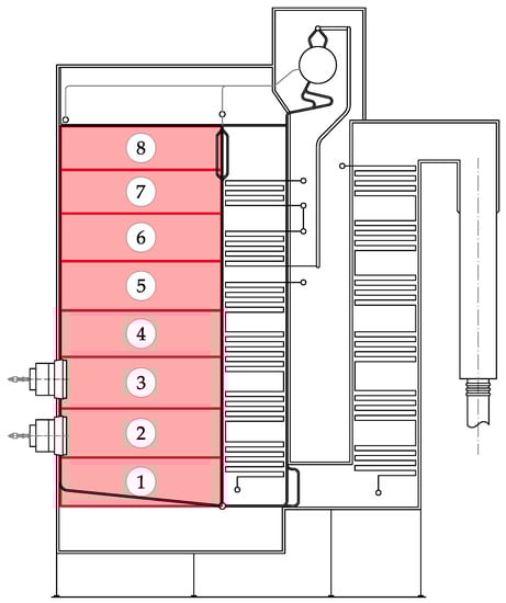
Figure 6.
Radiant chamber of the discussed steam boiler discretised via the AMPF model
In addition to the heat loading of the radiant tubes, it is possible to estimate the real state of the water–steam mixture if the real heat flux distribution is utilised for a following thermal-hydraulic calculation. By adding a standard AMPF result calculation, a critical location can be identified, e.g., where there is a risk of the so-called dry out and overheating of tubes.
4.3. Low-Cost Modelling of the Convection Tube Bank
Input data on the temperatures and flows (or speeds) of process fluids can be obtained by operational measurement or some previous simulations of the respective heat transfer equipment. However, experience of troubleshooting shows that the measured operating data is not as detailed as is necessary for equipment analysis. In the case of a new apparatus, of course, any data is completely missing and simplified or CFD models are irreplaceable. Another feasible approach is also utilisation of some of the established commercial software that is specialised for the heat exchanger modelling.
Although the CFD analysis [19] provided valuable information about the flue gas flow in the boiler space, it was not possible to model such complex fired equipment in detail. Thus, the tubular heat exchangers in the second part of the respective boiler were replaced by porous layers with the same pressure losses. This general CFD model [19] was able to investigate the flow field characteristics just above the discussed superheater. For the purpose of 2D calculations [10], the obtained velocity and temperature fields were divided by the number of tube columns. The flue gas temperatures and velocities in each of these sections (columns) serve as input data for the 2D calculation of the temperature distribution across the tube bundle. If such a CFD analysis is not available, it is possible to make use of data on flue gas thermal behaviour from the previous evaluation of the radiant chamber.
The inadequate simplification of commercial software, i.e., virtual mixing headers already mentioned in the second part of this work, was also noticed in the troubleshooting analysis of the superheater discussed here (see Figure 7). This simplification showed its impact on the steam temperature, which was averaged at the entrance of each tube pass. As an example, temperature data from the last two (the fifth and sixth) tube passes are listed in Table 2. The values at the end of the fifth pass and at the beginning of the sixth tube pass are written in italics to highlight the difference between the steam temperatures before and after averaging by the described software simplification.
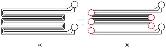
Figure 7.
Channel system of the steam superheater discussed here: (a) schematic of the real flow geometry, and (b) representation of the heat exchanger using virtual mixing headers.
Table 2.
Steam temperatures in the inlet and outlet zones of the tubes in the last two tube passes.
Information about the distribution of the fluid in the tubes was obtained using the isothermal model [25], which was fast because of its simplicity, and still sufficiently precise for calculation purposes. With respect to the location of the dividing and collecting manifold in the boiler (see Figure 8), heat transfer in these headers was neglected. Consequently, steam in the distributor (before dividing into the bundle) was assumed to be completely mixed at a constant temperature of 248.2 °C.
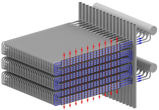
Figure 8.
The 2D method applied to a model of the tubular steam superheater. Hot fluid (flue gas) is shown in red, cold streams (steam) are outlined as blue lines.
The core of the modelling system is a 2D analysis of the heat distribution across the tube bundle. Due to the change in the direction of the steam flow, the overall calculation is divided into solutions of the so-called subexchangers, which represent the individual tube passes (also shown in Figure 8). Based on the cell method [22], the temperature field is obtained using dimensionless temperature formulae. Then, considering a general cell [i, j], the dimensionless outlet temperatures θout of both process fluids can be calculated with the following equations:
where P is temperature effectiveness and R the ratio of heat capacity rates of two fluids. Subscripts 1 and 2 denote variables related to the fluid with lower and higher heat capacity rate, respectively. In this case the hot stream (flue gas) had the lower heat capacity rate.
θout,1[i, j] = (1 − P1[i, j]) × θout,1[i − 1, j] + P1[i, j] × θout,2[i, j − 1]
θout,2[i, j] = (1 − R1[i, j] · P1[i, j]) × θout,2[i, j − 1] + R1[i, j] · P1[i, j] × θout,1[i − 1, j]
θout,2[i, j] = (1 − R1[i, j] · P1[i, j]) × θout,2[i, j − 1] + R1[i, j] · P1[i, j] × θout,1[i − 1, j]
The interconnection of the described models is represented schematically in Figure 9. As can be seen, the individual streams were kept separate across the whole tube bundle. Thus, the flow data avoided undesirable averaging. The presented technique yielded more accurate data on temperatures and mass flow rates of process fluid, thereby improving the accuracy of the predicted local overloading of heat transfer surface.
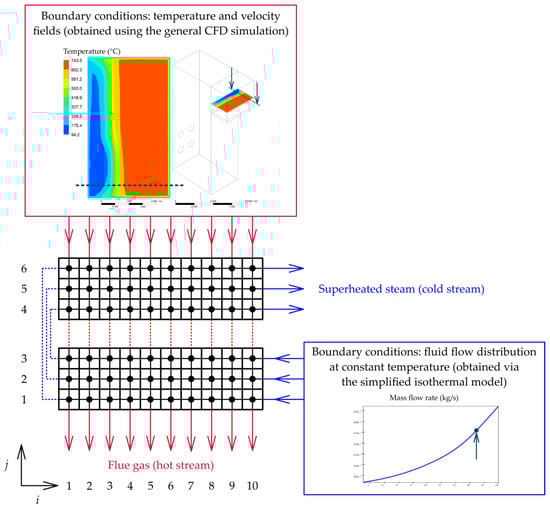
Figure 9.
Concept of the heat and fluid flow distribution modelling system illustrated on two passes of the heat exchanger in question. Flow data of the flue gas are provided by the previous general CFD analysis [19] while distribution of steam was pre-solved using a simplified model based on Bailey’s approach [25].
Not only Hewitt [22], but also other authors (e.g., Ptáčník [39] or the already-mentioned Cabezas-Gómez et al. [29]) point out that the thermal efficiency in Equation (2) is influenced by the flow arrangement (concurrent, countercurrent, and crossflow), mixing of each fluid, number of transfer units, and the ratio of heat capacity rates. Furthermore, Cabezas-Gómez et al. [29] argue that an effectiveness error of 0.01% may cause inaccuracies in the following calculations on the order of units of percent. The future research will, therefore, address the possibilities of P–NTU relationships, i.e., whether it is sufficient to use standard P–NTU formulas (a broad overview was given, e.g., by Shah and Sekulić [23]) without great inaccuracies, or it is appropriate and necessary to employ the so-called countercurrent coefficient described by Ptáčník [39]. In the current calculation, the overall heat transfer coefficient is assumed to be constant across the entire tube bundle. For that reason, the future work will also include refinements of this aspect of the calculation model, i.e., to specify the overall heat transfer coefficient in individual cells with respect to the local values of physical properties of process fluids.
5. Conclusions
In this paper, a novel framework for the efficient design of fired equipment has been introduced. The traditional thermal-hydraulic calculation of the radiant and convection section (i.e., the first phase of the calculation procedure) was supplemented by using low-cost modelling systems that take into account the real (non-uniform) distribution of heat flux and process fluids. Designing the combustion chamber was done using the AMPF model [7], the problematic heat exchanger in the convection section was analysed using the heat and fluid flow distribution modelling system [10] presented at the 21st Conference on Process Integration, Modelling and Optimisation for Energy Saving and Pollution Reduction PRES 2018. The application of these low-cost models (the second phase of calculations in the proposed framework) has been demonstrated in the industrial steam boiler case.
In the context of simplified methods, this framework is a logical outcome of the long-term development that has taken place at the Institute of Process Engineering of the Faculty of Mechanical Engineering, Brno University of Technology. First, the individual simplified models were unified for the analysis of thermal behaviour and flow distribution in combustion chambers and heat exchangers. Second, the presented framework links calculations of radiant and convection sections and offers a systematic approach to designing and fast rating calculations of complex fired equipment. It should be emphasized that the low-cost modelling procedure does not replace CFD analyses neither for purposes of troubleshooting nor for the final detailed design of the equipment. On the contrary, the described procedure enables detailed CFD analyses to concentrate effectively on critical locations identified using low-cost models.
Future work will focus on further refinement of 2D heat distribution calculations in the convection section.
Author Contributions
Conceptualization, Z.J.; methodology, Z.J. and D.F.; writing—original draft, D.F.; writing—review and editing, Z.J.; visualization, D.F.; supervision, Z.J.
Funding
This research was supported by the EU project Strategic Partnership for Environmental Technologies and Energy Production, funded as project No. CZ.02.1.01/0.0/0.0/16_026/0008413 by Czech Republic Operational Programme Research, Development and Education, Priority Axis 1: Strengthening capacity for high-quality research.
Acknowledgments
Thanks to M. Na’ who provided the authors with CDF data. Also, the authors wish to acknowledge the consultations offered by V. Turek.
Conflicts of Interest
The authors declare no conflict of interest.
References
- Gómez, A.; Fueyo, N.; Díez, L.I. Modelling and simulation of fluid flow and heat transfer in the convective zone of a power-generation boiler. Appl. Therm. Eng. 2008, 28, 532–546. [Google Scholar] [CrossRef]
- Hájek, J.; Jegla, Z. Standards for fired heater design: Analysis of two dominant heat flux variation factors. Appl. Therm. Eng. 2017, 125, 702–713. [Google Scholar] [CrossRef]
- Stehlík, P. Conventional versus specific types of heat exchangers in the case of polluted flue gas as the process fluid—A review. Appl. Therm. Eng. 2011, 31, 1–13. [Google Scholar] [CrossRef]
- API, Standard 530. Calculation of Heater-tube Thickness in Petroleum Refineries, 6th ed.; American Petroleum Institute: Washington, DC, USA, 2008. [Google Scholar]
- API, Standard 560. Fired Heaters for General Refinery Service, 4th ed.; American Petroleum Institute: Washington, DC, USA, 2007. [Google Scholar]
- Jegla, Z.; Kohoutek, J.; Stehlík, P. Design and operating aspects influencing fouling inside radiant coils of fired heaters operated in crude oil distillation plants. In Proceedings of the Heat Exchanger Fouling and Cleaning IX, Crete Island, Greece, 5–10 June 2011; Malayeri, M.R., Müller-Steinhagen, H., Watkinson, A.P., Eds.; pp. 7–14. [Google Scholar]
- Jegla, Z. Innovative adaptation of MPF model to recognition of thermal behaviour of operated industrial low emission burner system. Chem. Eng. Trans. 2016, 52, 667–672. [Google Scholar] [CrossRef]
- Jegla, Z.; Kilkovský, S.; Turek, V. Novel approach to proper design of combustion and radiant chambers. Appl. Therm. Eng. 2016, 105, 876–886. [Google Scholar] [CrossRef]
- Baukal, C.E. The John Zink Hamworthy Combustion Handbook: Volume 1—Fundamentals, 2nd ed.; CRC Press: Boca Raton, FL, USA, 2013; ISBN 9781439839621. [Google Scholar]
- Jegla, Z.; Fialová, D. Development of heat and fluid flow distribution modelling system for analysing multiple-distributed designs of process and power equipment. Chem. Eng. Trans. 2018, 70, 1471–1476. [Google Scholar] [CrossRef]
- Nekvasil, R.; Jegla, Z. Boiler reheater chamber cracking analysis. All Power 2014, 5, 11–13. [Google Scholar]
- Aslam Bhutta, M.M.; Hayat, N.; Bashir, M.H.; Khan, A.R.; Ahmad, K.N.; Khan, S. CFD applications in various heat exchangers design: A review. Appl. Therm. Eng. 2012, 32, 1–12. [Google Scholar] [CrossRef]
- Turek, V.; Fialová, D.; Jegla, Z. Efficient flow modelling in equipment containing porous elements. Chem. Eng. Trans. 2016, 52, 487–492. [Google Scholar] [CrossRef]
- Gandhi, M.S.; Ganguli, A.A.; Joshi, J.B.; Vijayan, P.K. CFD simulation for steam distribution in header and tube assemblies. Chem. Eng. Res. Des. 2012, 90, 487–506. [Google Scholar] [CrossRef]
- Zhou, J.; Sun, Z.; Ding, M.; Bian, H.; Zhang, N.; Meng, Z. CFD simulation for flow distribution in manifolds of central-type compact parallel flow heat exchangers. Appl. Therm. Eng. 2017, 126, 670–677. [Google Scholar] [CrossRef]
- Poursaeidi, E.; Arablu, M. Using CFD to study combustion and steam flow distribution effects on reheater tubes operation. J. Fluids Eng. 2011, 133, 051303:1–051303:11. [Google Scholar] [CrossRef]
- Jegla, Z.; Vondál, J.; Hájek, J. Standards for fired heater design: An assessment based on computational modelling. Appl. Therm. Eng. 2015, 89, 1068–1078. [Google Scholar] [CrossRef]
- Galindo-García, I.F.; Vázquez-Barragán, A.K.; Rossano-Román, M. CFD simulations of heat recovery steam generators including tube banks. In Proceedings of the ASME 2014 Power Conference (POWER 2014), Baltimore, MD, USA, 28–31 July 2014; POWER2014-32261. pp. 1–9. [Google Scholar] [CrossRef]
- Naď, M.; Jegla, Z.; Létal, T.; Lošák, P.; Buzík, J. Thermal load non-uniformity estimation for superheater tube bundle damage evaluation. MATEC Web Conf. 2018, 157, 02033:1–02033:10. [Google Scholar] [CrossRef]
- Manickam, M.; Schwarz, M.P.; Perry, J. CFD modelling of waste heat recovery boiler. Appl. Math. Model. 1998, 22, 823–840. [Google Scholar] [CrossRef]
- Lan, J.; Zhu, L.; Zhao, J. Modeling and Analysis of Cross-Flow Heat Exchanger Based on the Distributed Parameter Method. In Proceedings of the ASME 2012 International Mechanical Engineering Congress & Exposition (IMECE 2012), Houston, TX, USA, 9–15 November 2012; IMECE2012-86235. pp. 417–425. [Google Scholar] [CrossRef]
- Gaddis, E.S. Effectiveness of multipass shell-and-tube heat exchangers with segmental baffles (cell method). In Heat Exchanger Design Handbook; Hewitt, G.F., Ed.; Begell House: New York, NY, USA, 1998; ISBN 1-56700-094-0. [Google Scholar]
- Shah, R.K.; Sekulić, D.P. Fundamentals of Heat Exchanger Design; John Wiley & Sons: Hoboken, NJ, USA, 2003; pp. 256–258. ISBN 0-471-32171-0. [Google Scholar]
- Bajura, R.A.; Jones, E.H. Flow Distribution Manifolds. J. Fluids Eng. 1976, 98, 654–665. [Google Scholar] [CrossRef]
- Bailey, B.J. Fluid flow in perforated pipes. J. Mech. Eng. Sci. 1975, 17, 338–347. [Google Scholar] [CrossRef]
- Ngoma, G.D.; Godard, F. Flow distribution in an eight level channel system. Appl. Therm. Eng. 2005, 25, 831–849. [Google Scholar] [CrossRef]
- Cho, E.S.; Choi, J.W.; Yoon, J.S.; Kim, M.S. Modeling and simulation on the mass flow distribution in microchannel heat sinks with non-uniform heat flux conditions. Int. J. Heat Mass Transf. 2010, 53, 1341–1348. [Google Scholar] [CrossRef]
- Baek, S.; Lee, C.; Jeong, S. Effect of flow maldistribution and axial conduction on compact microchannel heat exchanger. Cryogenics 2014, 60, 49–61. [Google Scholar] [CrossRef]
- Cabezas-Gómez, L.; Navarro, H.A.; Saiz-Jabardo, J.M. Thermal performance of multipass parallel and counter-cross-flow heat exchangers. J. Heat Transf. 2007, 129, 282–290. [Google Scholar] [CrossRef]
- Pignotti, A.; Shah, R.K. Effectiveness-number of transfer units relationships for heat exchanger complex flow arrangements. Int. J. Heat Mass Transf. 1992, 35, 1275–1291. [Google Scholar] [CrossRef]
- Lobo, W.E.; Evans, J.E. Heat transfer in radiant section of petroleum heaters. Trans. Am. Inst. Chem. Eng. 1939, 35, 743–751. [Google Scholar]
- Jegla, Z.; Hájek, J.; Vondál, J. Numerical analysis of heat transfer in radiant section of fired heater with realistic imperfect geometry of tube coil. Chem. Eng. Trans. 2014, 39, 889–894. [Google Scholar] [CrossRef]
- Li, C.; Hu, G.; Zhong, W.; Cheng, H.; Du, W.; Qian, F. Comprehensive simulation and optimization of an ethylene dichloride cracker based on the one-dimensional Lobo–Evans method and computational fluid dynamics. Ind. Eng. Chem. Res. 2013, 52, 645–657. [Google Scholar] [CrossRef]
- Morales-Fuentes, A.; Polley, G.T.; Picón-Núñez, M.; Martínez-Martínez, S. Modeling the thermo-hydraulic performance of direct fired heaters for crude processing. Appl. Therm. Eng. 2012, 39, 157–162. [Google Scholar] [CrossRef]
- Hewitt, G.F.; Shires, G.L.; Bott, T.R. Process Heat Transfer, 1st ed.; CRC Press: Boca Raton, FL, USA, 1994; ISBN 9780849399183. [Google Scholar]
- Tucker, R.; Ward, J. Identifying and quantifying energy savings on fired plant using low cost modelling techniques. Appl. Energy 2012, 89, 127–132. [Google Scholar] [CrossRef]
- Jegla, Z. Development of modified plug-flow furnace model for identification of burner thermal behavior. Chem. Eng. Trans. 2013, 35, 1195–1200. [Google Scholar] [CrossRef]
- Jegla, Z.; Horsák, J.; Turek, V.; Kilkovský, B.; Tichý, J. Validation of developed modified plug-flow furnace model for identification of burner thermal behaviour. Chem. Eng. Trans. 2015, 45, 1189–1194. [Google Scholar] [CrossRef]
- Ptáčník, R. Analysis, Synthesis, and Retrofit Design of Heat Exchanger Networks Containing Multipass Crossflow Heat Exchangers. Ph.D. Thesis, Brno University of Technology, Brno, Czech Republic, 1991. [Google Scholar]


© 2019 by the authors. Licensee MDPI, Basel, Switzerland. This article is an open access article distributed under the terms and conditions of the Creative Commons Attribution (CC BY) license (http://creativecommons.org/licenses/by/4.0/).