Abstract
Due to the uncertainty of the power load and the randomness of distributed generations, low-voltage direct current (LVDC) bus voltage fluctuation will greatly affect the safety of an energy router-enabled direct current (DC) microgrid. In this paper, a power feedforward control strategy based on a dual active bridge (DAB) DC/DC converter in an energy router-based DC Microgrid is proposed. Based on this strategy, the LVDC bus voltage is controlled by virtual inertia control of the DC microgrid, instead of by the DAB converter. Thus, two benefits of the proposed strategy can be achieved: the power feedforward control can be realized, to mitigate the voltage fluctuation range of the LVDC bus; and the modulation algorithm in the DAB converter can be simplified. Experimental results verify the correctness and effectiveness of the proposed control method.
1. Introduction
In recent years, with the depletion of fossil energy resources and the increasing environmental contamination, distributed generations (DGs) have obtained large-scale development. At the same time, the proportion of direct current (DC) loads, like cell-driven vehicles, frequency conversion equipment, light emitting diode (LED) lighting, and information equipment, is increasing, and so the demand for DC power is too [1,2,3]. The proposal of energy internet concepts also promotes the development of the DC microgrid [4,5]. A DC microgrid has the advantages of high efficiency, large power supply capacity, good anti-interference, high reliability, relatively simple control, and low power loss, and so has attracted extensive attention [6,7,8].
A traditional DC microgrid uses economical and reliable line frequency transformer to achieve electrical isolation and voltage matching [9]. However, its large size and weight, low power density, and the lack of continuous regulation and integrated control of the voltage and current lead to the bottlenecks of large-scale grid connection of the DC microgrid. In this paper, the energy router (ER), which combines electrical isolation, voltage conversion, and power regulation, has attracted widespread attention from many scholars [10].
At present, research on the combination of ERs and microgrids mainly focuses on system architecture [11,12], energy management [13,14,15], and ER control strategy [16,17]. In [11], a new type of cascaded ER and DC microgrid was envisioned, and a simple master–slave control was introduced to regulate the low-voltage direct current (LVDC) bus voltage of the isolation stage, which alleviated the computational burden on the controller in stage 2. In [12], the authors proposed a novel power distribution system framework for plug-and-play deployment of DGs and distributed energy storage equipment. In [13,14], a novel DC microgrid structure based on an ER was proposed, where an energy management method for the ER that emphasized the function of distributed energy storage equipment was designed. In [15], for the sake of guaranteeing the active power sharing and autonomous operation of the hybrid microgrid, a novel hybrid microgrid droop control strategy was studied. A comparative analysis of different ER topologies was discussed in [16], incorporating the basic cascaded H-bridge-based method and modular multilevel converter (MMC)-based topologies. The structure design, control method, component level simulations, and operation strategies of MMC based ER was proposed in [17].
However, in practical applications, when the dynamic response difference between the ER and the microgrid is large, the LVDC capacitor as the energy buffer unit is prone to voltage and power imbalance, resulting in an increase in DC voltage dynamic fluctuation and a decrease of system stability. To solve this problem, Shi et al. have drawn on the experiment of cascade rectifiers, and proposed a new d–q vector control method to decrease the current distortion rate on the main grid aspect [18]. At the same time, their paper also proposes a novel voltage feedforward control strategy to achieve the voltage sharing problem of cascaded dual active bridges (DAB). Based on [18], Zhao et al. propose a new DC-side power and voltage balance method based on the d–q vector decoupling control [19]. The method is simple in control and can simultaneously achieve a balance of voltage and power. In [20], the small-signal model of the ER was given for the first time. Combined with the small signal model, a new cascaded DAB power and voltage equilibrizing control method was proposed. The proposed control strategy had a good dynamic response, and the DC voltage equilibrizing was implemented by the DAB converter. In [21], a model predictive control with a current stress-optimized (MPC-CSO) strategy based on dual-phase shift (DPS) control was proposed to gain the dynamic behavior, equilibrize the transmission power, and accomplish the current-stress strategy. However, the overall control strategy of suppressing the fluctuation of LVDC voltage and improving the dynamic response speed of the DAB converter in an ER-based DC microgrid has not been considered in the research process.
In this paper, combined with the virtual inertia control method of a DC microgrid, a novel power feedforward control method based on DAB transmission power characteristics is proposed. The proposed control strategy can effectively restrain the fluctuation range of the LVDC bus voltage. Meanwhile, the modulation algorithm of the system can be simplified, because the LVDC bus voltage is controlled by virtual inertia control of the DC microgrid. Furthermore, because no additional voltage and current sensors are added, the control strategy is easily performed by the digital signal processor (DSP), and the cost and the reliability of system are reduced and enhanced, respectively.
The structure of this paper is as follows. Section 2 gives a description of the ER-enabled DC microgrid, including the structure of the ER and DC microgrid. Section 3 describes the system control strategy, including the proposed virtual-inertia-based power feedforward control method. A small power system test prototype to verify the performance of the proposed control strategy is built in Section 4. Section 5 is devoted to the conclusions.
2. Description of an Energy Router-Based Direct Current Microgrid
Figure 1 shows the DC microgrid structure with an ER interface, which mainly consists of an AC grid, distributed power generation cell, energy storage unit, load, and ER. The ER main circuit includes a pre-stage rectification unit, a high-voltage DC side storage capacitor, a DAB converter unit, a low-voltage DC side storage capacitor, and an inverter unit. In Figure 1, 12 kV and 7.2 kV are the three-phase and single-phase AC line voltage, respectively.
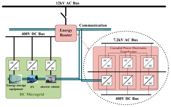
Figure 1.
Structure diagram of an energy router (ER)-based direct current (DC) microgrid.
When the DC microgrid is linked to the AC grid, the grid maintains the balance between supply and demand within the network. The grid maintains the DC voltage through the ER. DGs are in the maximum output mode. The battery was charged at the rated current when not fully charged. Among them, the DC microgrid load is mainly based on the constant power load. When the DC microgrid is operated off-grid, it can be operated through the DAB level of ER. At this time, the balance of supply and demand in the network is regulated by energy storage. When the energy storage has exceeded the adjustment range, the load shedding can be considered to keep the stability of the LVDC.
3. Control System of an Energy Router-Based Direct Current Microgrid
The proposed control strategy mainly combines the virtual inertia of a DC microgrid and DAB converter power transmission characteristics. This section first analyzes the principle of LVDC instability under traditional proportional integral (PI) control, and then proposes a power feedforward control strategy based on the power transmission characteristics of a DAB. The power loss of the converter is ignored in the calculation. It is worth mentioning that the proposed control method is still applicable under the circumstance of bidirectional flow.
3.1. Direct Current Bus Voltage Analysis of a Direct Current Microgrid with an Energy Router
Figure 2 shows a schematic diagram of the internal power balance of the ER-based DC microgrid.
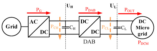
Figure 2.
Power flow diagram of an ER-based DC microgrid.
Where represents the output power of the grid. When the system is off-grid, . is the power flowing through high-voltage direct current capacitor. When it is charging, is positive; otherwise, is negative. represents the power flowing through the DAB converter. represents the power flowing through the LVDC capacitor. is the ER output power. is the power required by the DC microgrid, including the sum of the DGs, the energy storage cell, and the power consumption unit. In the case of ignoring the line impedance, = . and are the HVDC bus voltage and the LVDC bus voltage, respectively.
Although there are many control strategies for an ER-based DC microgrid, the relationship between the active power transferred by DAB and injected into the low voltage DC bus can be expressed as [22]
When the DC microgrid is operating in the steady state, = 0. In this case, = . When the DC microgrid is disturbed, the power increases or decreases (), and the unbalanced power will bring out the DC bus voltage to rise or fall . To restrain the DC bus voltage undulation, the traditional method uses the PI controller for control [19], and its control block diagram is shown in Figure 3.
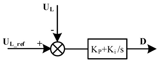
Figure 3.
Traditional control block diagram of a dual active bridge (DAB).
Where is the reference value of LVDC bus voltage, and are the PI controller parameters, and is the DAB phase shift amount.
In a traditional control strategy, by adjusting the phase shift angle between the two square waves of the primary and secondary sides, the amplitude and phase of the voltage applied across the series inductor can be controlled to control the magnitude and flow direction of the transmission power. Although the traditional PI control method can keep the LVDC bus voltage to a certain extent, its disadvantages are also obvious. In the traditional PI control method, the power and voltage control of DAB is realized only through a PI controller, resulting in a slow dynamic response. It is worth mentioning that in the ER-enabled DC microgrid, the variation of DC bus voltage will become more violent, due to the volatility and transitory of the DGs. In this case, the power exchange between the ER and DC microgrid becomes more frequent, and the traditional PI controller may not be applicable at this time.
3.2. Direct Current Microgrid Virtual Inertia Analysis
In the AC microgrid, the active power frequency control of the virtual synchronous generator (VSG) emulates the inertia, damping characteristics, and primary frequency characteristics of the synchronous generator. Assuming that the number of pole pairs of the synchronous generator is 1, the mechanical equation of the VSG can be expressed as (2) [23]
where and are the active power reference and the electromagnetic power, respectively; is the frequency damping coefficient; and are respectively the angular frequency of the VSG and the rated angular frequency of the grid; and is the virtual moment of inertia.
It can be seen from Equation (2) that due to the existence of , when the grid frequency is abrupt, the VSG can quickly adjust the active output, exhibiting a large inertia, and realizing the new energy power generation to actively support the grid frequency. describes the VSG output active power change when the frequency occurs in a unit change, so that the VSG has the ability to damp the frequency oscillation.
Comparing Equations (1) and (2), it is not difficult to find that the traditional DC microgrid control strategy has a weak ability to suppress the sudden transformation of the LVDC bus voltage, because of the lack of damping. If the DC microgrid can take virtual inertia control, the fluctuation of the LVDC bus voltage will be slowed down, and the dynamic response speed of ER will be relatively improved. Therefore, based on [23], combined with the P/V droop control of DC microgrid, a new control method that can enable DC microgrid virtual inertia is proposed. The expression is
where is the DC microgrid active power reference, is the rated LVDC bus voltage, is the DC microgrid virtual damping coefficient, and the expression of P/V droop control is [24]
where and are the required power and the output power of the DC microgrid, respectively.
3.3. Dual Active Bridge-Based Power Feedforward Virtual Inertia Control Analysis
A typical DAB converter circuit is composed of two symmetrical H-bridges and a high-frequency transformer, as shown in Figure 4. Traditional single-phase-shift (SPS) control is commonly directed at DAB converters. This control method is characterized by simple control, but there is circulating power. Furthermore, the converter has a higher efficiency only when the input voltage matches the output voltage. When the input voltage and the output voltage do not match with each other, the efficiency of the converter decreases, and the current stress increases, which increases the requirements on the switching device and the system cost. At the same time, for purpose of reducing the volume and weight of the DAB conversion, the switching frequency is usually increased, and as the current stress increases, the switching loss increases, thereby further reducing the efficiency of the system. DPS control can reduce current stress and improve converter efficiency. Therefore, this paper analyzes the power transfer characteristics of DAB converters based on DPS control.
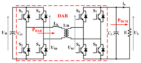
Figure 4.
DAB converter circuit.
A voltage and current schematic diagram of the DAB converter under the DPS control strategy is shown in Figure 5.
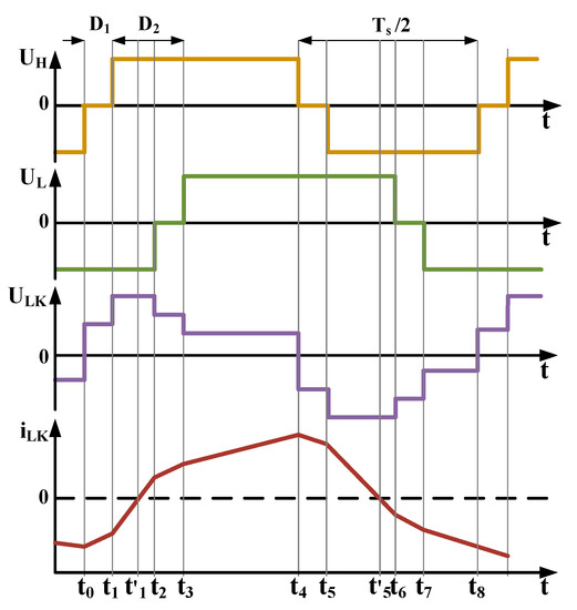
Figure 5.
Voltage and current of DAB converter in dual-phase shift (DPS) control.
From Figure 4 and Figure 5, the current run through the inductor can be expressed as
where and are the primary side and secondary side voltage of high frequency transformer, respectively, is time interval, and represents the turn ratio of the isolated transformer. Normally, .
Under DPS control, the average transmission power of the DAB converter is
where represents a switching interval.
Ignoring the system power losses, and combined with Equations (5) and (6), the transient transmission power of the DAB converter can be simplified to
where is the switching frequency of the DAB converter, is the transformation ratio, and , are the duty ratios of the high-voltage and the low-voltage H-bridges, respectively.
It can be seen from Equation (7) that in the case where the main circuit parameters are determined, the transmission power of the DAB converter is only related to , , , and , regardless of the initial current of the system. In fact, when the inductor current is biased, Equation (5) becomes
In Equation (8), is the bias of the inductor current relative to the inductor current at the steady state when it changes dynamically. In a control cycle, is exactly half of the positive and negative , so the integral of the voltage and the bias current portion is zero, and the power value of this part is also zero.
Since reducing the backflow power of the DAB converter can improve the overall system efficiency, and the proposed control method in this paper is easily implemented, the minimum backflow power constraint is added to the control strategy to improve the system efficiency.
As shown in Figure 3, and have a phase opposite to each other. The and time periods in Figure 3 have negative transmission power, indicating that the power in this phase will be sent back to the grid side.
Thus, under the DPS control, the total backflow power at the grid side of DAB converter is
The backflow power at the load side of DAB converter is
According to [25], the total backflow power is
where is the sum backflow power of the power and load sides.
According to Equation (7), when and , the DAB converter under DPS control can achieve maximum transmitted power:
where is the maximum transmitted power of DAB converter under DPS control.
Thus, the per-unit-value normalization of backflow power is
As can be seen from Equation (13), in order to achieve the minimum of , we should try to minimize .
However, the transmission power required by DAB should be satisfied before the power backflow is minimized. According to Equations (7) and (12), when , the per-unit-value normalization transmitted power of DAB converter can be expressed as
From Equation (14), The DPS control subscript per-unit value normalization transmitted power is only related to and , and the three-dimensional (3-D) per-unit-value normalization transfer power curve is shown in Figure 6.
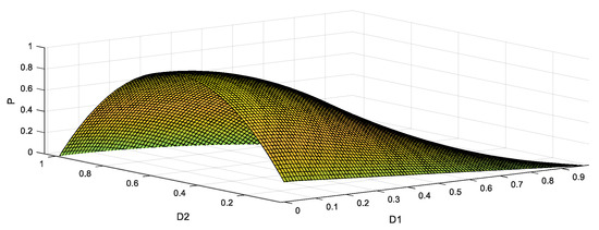
Figure 6.
The three-dimensional (3-D) per-unit-value normalization transfer power curve in DPS control.
As can be seen from Figure 6, when the DAB converter is controlled by DPS and transmits the same power, there are many different combinations of (, ) that can realize it. However, under each combination of (, ), the current stress of the converter is different. By analyzing the current stress characteristics of various combinations (, ) of the DAB converter at the same transmission power, the optimal combination of (, ) that can minimize the current stress of the converter at a certain power transmission can be obtained.
In the existing DAB output power and voltage control methods, the high volatility and indirectness of the DC microgrid are ignored [26], so the traditional control methods are often unable to be effectively implemented. For purpose of overcoming the inherent shortcomings of the traditional control strategies, this paper proposed a novel control strategy for an ER-enabled DC microgrid, on account of the virtual inertia control of DC microgrid. The proposed control strategy can simplify the DAB modulation algorithm while effectively inhibiting the LVDC bus voltage variation range.
When , according to Equation (7),
Substitute Equation (15) into Equation (4), and there is
Based on (4), (9), (15), and (16), the virtual inertia-based direct power feedforward control method proposed in this paper can be obtained. The control block diagram is shown in Figure 6.
In Figure 7, the block rectifier (black block) is the block diagram of the control strategy for the AC/DC converter [27]. The pulse width modulation (PWM) control strategy is mainly used for fast and stable regulation of DC bus voltage to ensure the stability of the AC/DC converter stage and DAB power exchange. However, in the rotating coordinate system, decoupling control is required due to the existence of coupling. Therefore, the block diagram of the AC/DC converter control strategy adopted in this paper is shown in the left part of Figure 6. and are the d-axis component and q-axis component value, respectively, after the grid side voltage is decoupled by dq transformation. In addition, and are the d-axis component and q-axis component value after the grid side current is decoupled by dq transformation, and and are the d-axis and q-axis component reference values, respectively. is the HVDC bus voltage reference, and is the synchronous rotation angular frequency.
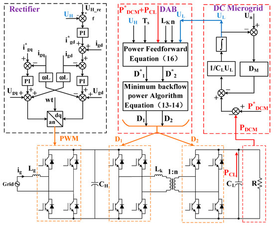
Figure 7.
Block diagram of the overall control of an ER-based DC microgrid.
The proposed control method is shown at the right part (red block) in Figure 7. The proposed control method contains two modules, “DC Microgrid” and “DAB”. “DAB” contains two submodules: “Power Feedforward control” and “Minimum backflow power algorithm”.
The “DC Microgrid” module refers to the fact that according to the change of the DC microgrid power, by combining with virtual inertial control and P/V droop control, the LVDC bus voltage can be obtained. Then, the information is passed to DAB block. In the case of ignoring switching losses, the power transmitted by the DAB shall be equal to the sum of the power required by the DC Microgrid and the LVDC capacitor.
With regard to the “Power Feedforward control” submodule, in combination with Equations (15) and (16), since the converter is operated with equivalent inductance parameter , the transformer ratio and switching frequency are basically stable. The variation of these quantities is not considered in this paper. In addition, for most energy conversion systems [17], the change of input voltage is relatively slow, so this paper does not consider the abrupt change of for the time being. Then, the simplified DAB output power can be written
According to the “DC Microgrid” block, and can be obtained by a DC microgrid and LVDC bus capacitance. Thus, the initial and can be obtained directly from Equation (17). In this case, and refer to values that are not optimized by the minimum backflow algorithm. It is worth mentioning that the power feedforward control proposed in this paper directly introduces the power of a DC microgrid into the control strategy of DAB.
In the “Minimum backflow power algorithm” submodule, with the “Power Feedforward control” block, the initial and can be obtained. According to Equations (13) and (14), and optimized by the minimum back-flow power algorithm are and . Thus, and are the final duty ratios, which transfer to the control strategy of the DAB converter.
Combined with the above analysis, the proposed virtual inertia power feedforward control method can be performed through the following steps:
- (1)
- According to the variation power of the DC microgrid, the value of LVDC bus voltage can be obtained by using the virtual inertia and P/V droop control method in the block “DC Microgrid”.
- (2)
- In the block “Power Feedforward control”, the initial duty ratio ( and ) of the DAB converter is calculated by Equations (15) and (16).
- (3)
- According to the block “Minimum backflow power algorithm”, the initial duty ratios ( and ) are optimized. Then, the optimal combination ( and ) that can minimize the current stress of the converter at a certain power transmission can be obtained.
- (4)
- The optimized duty ratios ( and ) are transformed into the driving pulse acting on the DAB converter by the DPS.
4. Experimental Results and Analysis
In order to validate the correctness of the proposed virtual–inertial direct-power feedforward control method for the ER-based DC microgrid, a low-power ER micro-network test prototype with DSP_TMS320F28335+FPGA_XC6SLX9 as the main controller was designed and constructed, as shown in Figure 8. The experimental setup parameters are shown in Table 1. Furthermore, the communication circuit is , and the system switch frequency is 19.2 kHz. The models of the IGBTs in the AC/DC front-end side stage and back-end side stage are , and the model of the IGBTs in DAB stage is .
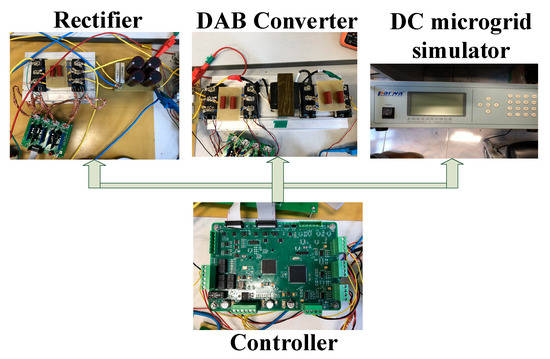
Figure 8.
The photo of ER-based DC microgrid.

Table 1.
Experimental setup parameters.
4.1. AC/DC Converter Verification
The AC current waveform and the DC side voltage waveform of the AC/DC rectifier stage are important indicators for verifying the control characteristics of the AC/DC rectifier stage. Figure 9a shows the DC bus voltage and the grid side current waveform. The grid side current presents a perfect sine waveform. For the distribution network, the AC/DC converter stage is equivalent to a purely resistive load. There is no harmonic pollution in the main power grid. The total harmonic distortion (THD) of the grid side voltage in the actual measurement is 4.2%, which is lower than the upper limit for the grid side voltage, and the THD of the grid-connected converter in the grid upper limit is less than 5%. The DC bus voltage waveform is shown in Figure 9b. According to the actual measurements, the DC bus voltage is stable at 400 V, its peak value is 410 V, its valley value is 390 V, and the DC voltage fluctuation is lower than 10 V, which is the design index of the system. The double frequency (100 Hz) ripple exhibited by the DC bus voltage is also consistent with the instantaneous power theory. Figure 9c,d shows the voltage transient waveforms under abrupt DC bus voltage change. According to the actual waveform, the DC bus voltage has good dynamic characteristics under fluctuation, and there is almost no overshoot. The transient process is short.
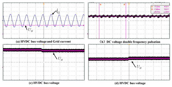
Figure 9.
The experimental waves of AC/DC converter.
4.2. Dual Active Bridge Converter Virtual Inertia-Based Power Feedforward Control Method Verification
Figure 10a shows the waveform of without the proposed virtual inertia-based power feedforward control strategy. From Figure 10a, after the power of DC microgrid drops suddenly at 0.07 s, and quickly rises to an unstable value of 605 V. Then, after a period of oscillation, stabilizes to 540 V. As can be seen from the figure, when the proposed control strategy is not adopted, has a large overshoot process. Figure 10b shows the waveform of with the proposed virtual inertia-based power feedforward control strategy. From Figure 10b, after the power of the DC microgrid drops suddenly at 0.07 s, slowly and smoothly rises to the desired value of 540 V. As can be seen from the figure, there is no overshoot with the proposed virtual inertia-based power feedforward control strategy.
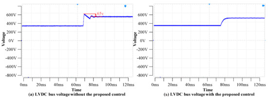
Figure 10.
The experimental waves of a DAB converter.
Figure 11a shows the waveform of without the proposed virtual inertia-based power feedforward control strategy. From Figure 11a, after the required power of the DC microgrid suddenly increases at 0.07 s, quickly drops to an unstable value of 280 V. Then, after a period of oscillation, stabilizes to 350 V. As can be seen from the figure, when the proposed control strategy is not adopted, has a large overshoot process. Figure 11b shows the waveform of with the proposed virtual inertia-based power feedforward control strategy. From Figure 11b, after the required power of DC microgrid suddenly increases at 0.07 s, slowly and smoothly drops to the desired value of 350 V. As can be seen from the figure, there is no overshoot with the proposed virtual inertia-based power feedforward control strategy.
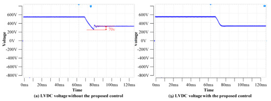
Figure 11.
The experimental waves of a DAB converter.
According to the experiment results, two kinds of control strategies can be adopted. First, there is the traditional droop control strategy. When the system power is unbalanced, the LVDC bus voltage changes rapidly, due to the change of the LVDC bus voltage set value. Because there is no inertia link in the controller, the LVDC bus voltage will have a large overshoot in the transient process, but its dynamic response is faster and the transient time is shorter. The second control strategy is the proposed virtual inertia-based power feedforward control method. Since there is a large inertia link in the control strategy, the dynamic adjustment of LVDC bus voltage will not have a large overshoot, but the transient time is longer than that of the traditional control strategy. By selecting appropriate control parameters, the control with no overshoot but a fast, dynamic response can be achieved.
4.3. Dual Active Bridge Converter Current/Switching Stress of the Switching Verification
Figure 12 shows the current and voltage waves of DAB converter under the DPS control strategy. It can be seen from Figure 12a that when the minimum backflow power algorithm is not adopted, the peak current of the inductance current is large and has a certain distortion rate. From Figure 12b, when the minimum backflow power algorithm is adopted, the maximum inductance current is lower than that when the algorithm is not adopted. Thus, the overall efficiency of the converter system can be improved by adopting the DPS control strategy of minimum backflow power compared with the traditional DPS control method.
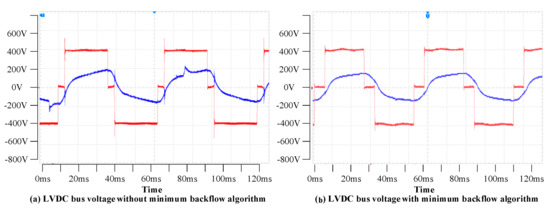
Figure 12.
The current and voltage waves of a DAB converter.
5. Conclusions
The problem of the low inertia of the ER-based DC microgrid and large fluctuation of LVDC bus voltage will endanger the reliable and stable manipulation of the DC microgrid and reduce the operating potency of the system. This paper proposes a power feedforward control strategy for ER-based DC microgrid applications. The main idea is to use DC microgrid virtual inertia control combined with DAB power transmission characteristics to slow down the change of LVDC bus voltage, and to simplify the modulation algorithm of DAB converter, for the purpose of improving system potency and stability. The DC microgrid virtual inertia control strategy combines the functions of virtual inertia and DC power-voltage droop, effectively enhancing the inertia of the DC microgrid and suppressing DC bus voltage fluctuations. The power feedforward control strategy based on the DAB power transmission characteristics can simplify the modulation algorithm, and the reliability of the system can be enhanced. The validity and efficacy of the proposed virtual inertia-based power feedforward control method can be verified by experimental results.
Future research directions will consider extending the proposed control strategy to a cascade structure. Due to the limitation of ER capacity, the cascading structure will become the trend of the future. The solid-state transformer experimental platform designed in this paper is only a theoretical verification platform, because its voltage level is 220 V AC. This voltage level is not sufficient for practical applications, so solid-state transformers that achieve high- to low-voltage conversion can be considered in the future.
Author Contributions
All the authors conceived and designed the study. Y.L. performed the experiment and wrote the manuscript, with guidance from Q.S. Q.S., D.W., and S.L. reviewed the manuscript and provided valuable suggestions.
Acknowledgments
This work was supported by the National Natural Science Foundation of China (NSFC) under Grant No. 61433004, No. 61573094, and No. 61773109.
Conflicts of Interest
The authors declare no conflict of interest.
References
- Nejabatkhah, F.; Li, Y.W. Overview of Power Management Strategies of Hybrid AC/DC Microgrid. IEEE Trans. Power Electron. 2015, 30, 7072–7089. [Google Scholar] [CrossRef]
- Xia, Y.; Wei, W.; Yu, M.; Wang, X.; Peng, Y. Power Management for a Hybrid AC/DC Microgrid with Multiple Subgrids. IEEE Trans. Power Electron. 2018, 33, 3520–3533. [Google Scholar] [CrossRef]
- Li, Y.S.; Zhang, H.G.; Liang, X.D.; Huang, B.N. Event-triggered based distributed cooperative energy management for multi-energy systems. IEEE Trans. Ind. Inform. 2018. [Google Scholar] [CrossRef]
- Sun, Q.Y.; Zhang, Y.B.; He, H.B. A Novel Energy Function Based Stability Evaluation and Nonlinear Control for Energy Internet. IEEE Trans. Smart Grid 2017, 8, 1195–1210. [Google Scholar] [CrossRef]
- Sun, Q.Y.; Han, R.K.; Zhang, H.G.; Zhou, J.G.; Guerrero, J.M. A Multi-Agent-based Consensus Algorithm for Distributed Coordinated Control of Distributed Generators in the Energy Internet. IEEE Trans. Smart Grid 2015, 6, 3006–3019. [Google Scholar] [CrossRef]
- Guerrero, J.M.; Loh, P.C.; Lee, T.; Chandorkar, M. Advanced Control Architectures for Intelligent Microgrids—Part II: Power Quality, Energy Storage, and AC/DC Microgrids. IEEE Trans. Ind. Electron. 2013, 60, 1263–1270. [Google Scholar] [CrossRef]
- Chang, Y.C.; Chang, H.C.; Huang, C.Y. Design and Implementation of the Battery Energy Storage System in DC Micro-Grid Systems. Energies 2018, 11, 1566. [Google Scholar] [CrossRef]
- Wang, R.; Sun, Q.Y.; Cheng, Q.F.; Ma, D.Z. The Stability Analysis of a Multi-Port Single-Phase Solid-State Transformer in the Electromagnetic Timescale. Energies 2018, 11, 2250. [Google Scholar] [CrossRef]
- Rodrigues, W.A.; Oliveira, T.R.; Morais, L.M.F.; Rosa, A.H.R. Voltage and Power Balance Strategy without Communication for a Modular Solid State Transformer Based on Adaptive Droop Control. Energies 2018, 18, 1802. [Google Scholar] [CrossRef]
- Liserre, M.; Buticchi, G.; Andresen, M.; Carne, G.D.; Costa, L.F.; Zou, Z.X. The Smart Transformer: Impact on the Electric Grid and Technology Challenges. IEEE Ind. Electron. Mag. 2016, 10, 46–58. [Google Scholar] [CrossRef]
- Wang, L.; Zhang, D.L.; Wang, Y.; Wu, B.; Athab, H.S. Power and Voltage Balance Control of a Novel Three-Phase Solid-State Transformer Using Multilevel Cascaded H-Bridge Inverters for Microgrid Applications. IEEE Trans. Power Electron. 2016, 31, 3289–3301. [Google Scholar] [CrossRef]
- Huang, A.Q.; Crow, M.L.; Heydt, G.T.; Zheng, J.P.; Dale, S.J. The Future Renewable Electric Energy Delivery and Management (FREEDM) System: The Energy Internet. Proc. IEEE 2011, 99, 133–148. [Google Scholar] [CrossRef]
- Yu, X.W.; She, X.; Zhou, X.H.; Huang, A.Q. Power Management for DC Microgrid Enabled by Solid-State Transformer. IEEE Trans. Smart Grid 2014, 5, 954–965. [Google Scholar] [CrossRef]
- Yu, X.W.; She, X.; Ni, X.J.; Huang, A.Q. System Integration and Hierarchical Power Management Strategy for a Solid-State Transformer Interfaced Microgrid System. IEEE Trans. Power Electron. 2014, 29, 4414–4425. [Google Scholar] [CrossRef]
- Loh, P.C.; Li, D.; Chai, Y.K.; Blaabjerg, F. Autonomous Operation of Hybrid Microgrid With AC and DC Subgrids. IEEE Trans. Power Electron. 2013, 28, 2214–2223. [Google Scholar] [CrossRef]
- López, M.; Briz, F.; Saeed, M.; Arias, M.; Rodríguez, A. Comparative analysis of modular multiport power electronic transformer topologies. In Proceedings of the 2016 IEEE Energy Conversion Congress and Exposition (ECCE), Milwaukee, WI, USA, 18–22 September 2016; pp. 1–8. [Google Scholar]
- Wang, X.Y.; Liu, J.J.; Ouyang, S.D.; Xu, T.T.; Meng, F.; Song, S.G. Control and Experiment of an H-Bridge-Based Three-Phase Three-Stage Modular Power Electronic Transformer. IEEE Trans. Power Electron. 2016, 31, 2002–2011. [Google Scholar] [CrossRef]
- Shi, J.J.; Gou, W.; Yuan, H.; Zhao, T.F.; Huang, A.Q. Research on Voltage and Power Balance Control for Cascaded Modular Solid-State Transformer. IEEE Trans. Power Electron. 2011, 26, 1154–1166. [Google Scholar] [CrossRef]
- Zhao, T.F.; Wang, G.Y.; Bhattacharya, S.; Huang, A.Q. Voltage and Power Balance Control for a Cascaded H-Bridge Converter-Based Solid-State Transformer. IEEE Trans. Power Electron. 2013, 28, 1523–1532. [Google Scholar] [CrossRef]
- Pugliese, S.; Andresen, M.; Mastromauro, R.A.; Buticchi, G.; Stasi, S.; Liserre, M. A New Voltage Balancing Technique for a Three-Stage Modular Smart Transformer Interfacing a DC Multibus. IEEE Trans. Power Electron. 2018. [Google Scholar] [CrossRef]
- An, F.; Song, W.S.; Yu, B.; Yang, K.X. Model Predictive Control with Power Self-Balancing of the Output Parallel DAB DC–DC Converters in Power Electronic Traction Transformer. IEEE J. Emerg. Sel. Top. Power Electron. 2018, 6, 1806–1818. [Google Scholar] [CrossRef]
- Wang, R.; Sun, Q.Y.; Ma, D.Z.; Liu, Z.W. The Small-Signal Stability Analysis of the Droop-Controlled Converter in Electromagnetic Timescale. IEEE Trans. Sustain. Energy 2019. [Google Scholar] [CrossRef]
- Wu, W.H.; Chen, Y.D.; Luo, A.; Zhou, L.M.; Zhou, X.P.; Yang, L.; Dong, Y.T.; Guerrero, J.M. A Virtual Inertia Control Strategy for DC Microgrids Analogized With Virtual Synchronous Machines. IEEE Trans. Ind. Electron. 2017, 64, 6005–6016. [Google Scholar] [CrossRef]
- Vandoorn, T.L.; De Kooning, J.D.M.; Meersman, B.; Vandevelde, L. Improvement of active power sharing ratio of P/V droop controllers in low-voltage islanded microgrids. In Proceedings of the 2013 IEEE Power & Energy Society General Meeting, Vancouver, BC, Canada, 21–25 July 2013; pp. 1–5. [Google Scholar]
- Zhao, B.; Song, Q.; Liu, W.H. Efficiency Characterization and Optimization of Isolated Bidirectional DC–DC Converter Based on Dual-Phase-Shift Control for DC Distribution Application. IEEE Trans. Power Electron. 2013, 28, 1711–1727. [Google Scholar] [CrossRef]
- Hou, N.; Song, W.S.; Wu, M.Y. Minimum-current-stress scheme of dual active bridge DC-DC converter with unified phase-shift control. IEEE Trans. Power Electron. 2016, 31, 8552–8561. [Google Scholar] [CrossRef]
- Vladimir, B.; Vikram, K. A New Mathematical Model and Control of a Three-Phase AC–DC Voltage Source Converter. IEEE Trans. Power Electron. 1997, 12, 116–123. [Google Scholar]
© 2019 by the authors. Licensee MDPI, Basel, Switzerland. This article is an open access article distributed under the terms and conditions of the Creative Commons Attribution (CC BY) license (http://creativecommons.org/licenses/by/4.0/).