Abstract
In this paper, a class of mixed controller is designed for an energy router (ER) within the scenario of an energy Internet (EI). The considered ER is assumed to have access with photovoltaic panels, wind turbine generators, micro-turbines, fuel cells, diesel engine generators, battery energy storage devices, flywheel energy storage devices, loads, and other ERs. Two types of control targets are considered. First, due to the access of large-scale renewable energy sources, the DC bus voltage deviation within the ER system shall be regulated. Second, an optimal energy management strategy shall be achieved, such that the autonomous power supply-demand balance within each ER is achieved with priority and the rational utilization of controllable power generation devices and energy storage devices are realized. When these objectives are considered simultaneously, the control issues with respect to ER is formulated as a mixed robust control problem with analytical solutions provided. Several numerical examples are given, and the feasibility and effectiveness of the proposed method are demonstrated.
1. Introduction
1.1. Motivation
In recent years, with the deterioration of the global environmental issues and the development of renewable energy technology, researchers are increasingly inclined to use renewable energy, e.g., wind power, solar power, hydro power, etc. However, power generated by renewable energy sources (RESs) is flexible and unpredictable, resulting in great obstacles to access to traditional power systems. Being regarded as a new version of the smart grid, energy Internet (EI) integrates the most advanced energy technology and communication technology, providing a basic platform for energy control and transmission [1,2].
Power network nodes, composed of distributed energy acquisition devices, distributed energy storage devices, and various types of loads, can be interconnected within EI scenarios. Besides, energy peer-to-peer exchange and bi-directional energy flow can be realized simultaneously in EI [3]. As a new energy architecture, EI can be compatible with conventional power grids and can make full use of distributed RESs [4]. It also provides a common energy exchange and sharing platform for energy consumers [5]. It is suggested that EI can help to integrate the energy industry chain and form the mechanism of supply-demand interaction and trade [6]. Short-term load forecasting can be achieved in real time to achieve demand response management [7].
Compared with other forms of power systems, EI has many key technical characteristics. A large number of distributed renewable power generation devices are interconnected in EI. Within the scope of high permeability of RESs, there is a great difference between energy control and management of EI and those of traditional power grids [8]. Notably, distributed RESs shall be the main body of future EI and they have disadvantages such as uncertain and intermittent power output [9]. Meanwhile, the changes of real-time electricity price and operation mode are also random [10]. In this sense, stochastic characteristics appear in EI systems and the related control, optimization, and scheduling are becoming challenging [11]. More importantly, EI operates in a highly informative environment. The implementation of distributed power generation, energy storage, and demand side response lead to huge data, including meteorological information, electricity usage custom and energy storage status [12]. With the popularization and application of advanced measurement technology, the number of intelligent terminals with measurement function in EI would increase greatly, and the amount of the generated data would also increase dramatically [13]. Finally, EI is a deeply coupled system of material, energy and information [14]. As a super-large-scale complex network with interdependence of society, information, and physics, EI has broader openness and greater system complexity than traditional power grids, showing complex dynamical characteristics [15].
In order to realize the interconnection and scheduling of energy networks and to upgrade the energy production and distribution, a new type of electrical device, called energy router (ER), has been proposed and designed [16]. Similar to the role of routers in the Internet, ERs can be viewed as energy forwarding and caching nodes in EI. More importantly, ERs can also effectively control the power quality and optimize the energy transmission cost by collecting and processing energy information.
1.2. Literature Review
The concept of ER was first proposed by American researchers. In 2008, a project called the future renewable electric energy delivery and management (FREEDM) system [17] studied a new grid structure based on renewable energy generation and distributed energy storage devices. Following the core of network technology in the field of information, FREEDM researchers put forward the concept of ER and implemented its prototype design [18]. In the same year, a Swiss research team developed the so-called energy hub [19]. The hubs are derived from the concept of hubs in computer science, also known as energy control centers. In 2013, Japanese researchers put forward the concept of power router which is able to dispatch and manage the power of a certain area.
Power conversion is an indispensable function of ER that connects various forms of RESs. The terminals in the energy network are connected, such that the controllability of energy transmission is greatly enhanced. For power energy, an ER structure composed of communication platform, controller, and solid-state transformer is proposed in [20]. The functions of ER in the current energy environment are summarized in [21], while the structure composed of system controller, network adaptive model, DC bus and sockets, and circuit breakers with multiple interface standards is also introduced. A hierarchical ER design is proposed in [22], where information support layer provides information support for the energy control layer, and it is able to integrate with the protection and other basic components to form the unique security function of ER. Furthermore, functional layer can realize energy control, optimization management, safety protection, maintenance, etc. Moreover, there are extensive studies on ER architecture, most of which are based on solid-state transformers and other power electronic conversion devices [23,24,25,26,27].
The research related with energy routing has been popular. A class of energy routing algorithm based on graph theory within local area energy network has been studied in [28]. In reference [29], stochastic optimal controllers are designed in ERs and micro-turbines (MT), such that the bottom-up energy management principle in EI is achieved. In reference [30], energy routing for delay-tolerant loads and mobile energy buffers has been investigated. Based on economic dispatching requirement, the corresponding energy routing strategy is reported in [31]. For low-voltage distribution power grids, an open energy routing network has been investigated in [32]. For an islanded microgrid (MG), non-fragile controllers are designed for ERs and other controllable power generation devices, such that the DC bus voltage deviation is regulated [33]. For other related research outputs on ERs, readers can refer to [34,35,36], and the references therein. It is notable that in the field of EI, there has been few work focusing on both problems of frequency/voltage regulation and optimal operation cost management for ERs from the control perspective. In addition, when power dynamics of various electrical devices are considered, most of the works focus on control issues within a short time scale only, which is restrictive [33].
1.3. Contribution
In this paper, we consider the problems of voltage regulation and optimal operation cost management simultaneously for the ER system that is designed based on the DC bus topology. The considered ER system is assumed to have access to renewable power generation devices (i.e., photovoltaics (PVs) and wind turbine generators (WTs)), controllable power generation devices (i.e., MTs, diesel engine generators (DEGs), and fuel cells (FCs)), energy storage devices (i.e., battery energy storages (BES) and flywheel energy storages (FES)), as well as other ERs. The similar connection topology has been used in many works; see, [33,36]. The power dynamics of ER system are modelled as ordinary differential equations (ODEs) and parameter uncertainty is taken into consideration, due to unavoidable modelling errors. For the considered ER system, we formulate the voltage alleviation issue as a robust control problem (the definition of control is introduced in Appendix A), whereas the energy management optimization issue is formulated as an optimal control (also known as control) problem. Our purpose is to design a controller for the ER system such that both and performances are satisfied simultaneously. Next, a mixed control problem is formulated and solved analytically. From the control perspective, two theorems are presented as the main results. Simulations based on different scenarios are performed to show the feasibility and effectiveness of the proposed method. It is notable that restriction of this article is that our research is focused on new ER system based on future EI infrastructure, in the sense that there exists no current grid regulation or grid code regarding EI scenario.
The main contribution of this paper can be outlined as follows.
This is the first time that a mixed robust controller is designed for ER system within an EI scenario, considering norm bounded parameter uncertainties. In this sense, the following targets are achieved simultaneously. (1) The DC bus voltage deviation of the studied ER system is regulated. (2) The considered ER system is robust against parameter uncertainty. (3) The autonomous power supply-demand balance within each ER is achieved with priority. (4) The rational utilization of controllable power generation devices and energy storage devices is achieved. (5) We are able to adjust the weighting factors in the objective functions, which leads to a more flexible solution for the operation of the ER system. (6) Although the considered ER system is expressed with short-term power dynamics, a long-term operation target can be achieved technically. (7) Based on real-world data, different scenarios are considered for simulations and the advantage of our proposed approach over the conventional ones is demonstrated.
2. System Modelling
In this paper, a general type of ER is considered within an EI scenario. The physical structure of the considered ER system is presented in Figure 1.
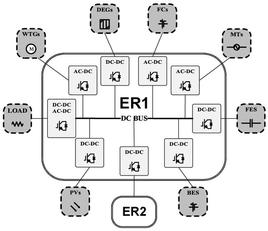
Figure 1.
The studied energy router (ER) system.
Let us denote the considered ER system as which has access to loads, PVs, WTs, MTs, DEGs, FCs, BESs, FESs and another ER system (denoted as energy router 2 ()). For energy router 1 (), we assume that power input mainly relies on power generation by massive PVs and WTs, whereas distributed controllable devices MTs, DEGs and FCs are considered to be complementary power generation devices. Influenced by changeable weather conditions, such as solar radiation and wind speed, the varying power outputs of PVs, WTs and loads may cause excessive ER’s DC bus voltage deviation. In order to compensate power deviations and to absorb surplus electric power, BESs and FESs are equipped and connected to .
The balance of power supply and demand within the considered ER system is expressed as (time omitted):
in which represents the surplus power which is transmitted from to .
Linearized state-space model has been widely used in the application of the robust MG control issues. Within a relatively small-scale time period, power dynamics of RESs, energy storage devices, distributed controllable power generation devices and loads can be expressed as ODEs. Such linearized state-space model is mostly used for the controller designing. (For illustrations, readers can refer to [33,37,38]).
The power utilization of load devices and power generated by PVs and WTs are heavily affected by time-varying environmental conditions, such as customer behaviors at demand side, solar radiation, and wind speed. Besides, the parameter measurement errors of the considered ER system are inevitable. Thus, parameter uncertainties are considered for the dynamical model of .
Then, the power dynamics of the considered ER system in Figure 1 can be presented with ODEs as follows.
where , are system coefficients in the linearized voltage deviation equation.
Let us denote vector vector and vector .
Then, the power dynamics in (2) can be rewritten in the following elaborated expression (time omitted),
In the state-space control system (3), is system state, is system control input, is system disturbance input. The coefficient matrices and in system (3) are presented in Appendix B. The parameter uncertainties and in (3) are of the form given in (4).
where is an unknown time-varying matrix, satisfying
where is the identity matrix, and , and are real constant matrices whose values are obtained from engineering practice. The uncertainties formulated in (4) and (5) are widely used [33,39].
3. Problem Formulation
In this section, we formulate the hybrid problem of maintaining ER’s DC bus voltage stability and realizing an optimal energy dispatching strategy of ER into a robust mixed control problem.
3.1. Robust Control Problem Formulation
In the field of power systems, robust control theory has been applied to voltage alleviation problems [33] and frequency regulation issues [37,38]. For the considered DC-type ER, to alleviate its bus voltage deviation, proper control input signals have to be designed for MTs, FCs, and DEGs. In this section, a robust control problem is formulated to achieve the desired DC bus voltage stability.
To maintain the voltage stability, both system internal parameter uncertainty and system external disturbance inputs shall be considered. First, the definition of robustly stable is given.
Definition 1.
For all system parameter uncertainties and , if is achieved for , then ER system (3) with and is said to be robustly stable.
Second, for the considered ER system, in order to guarantee the DC bus voltage stability against external disturbance input, we apply the definition of the time domain performance [39] to describe the desired anti-interference performance against changeable output power of PVs, WTs and loads. The DC bus voltage deviation in (2) is viewed as the controlled output of the ER system, which is denoted as . Then, we have , where matrix
The definition of performance is presented as follows.
Definition 2.
[39] Given a scalar , the performance of the ER system is defined as , where norm is defined as The scalar is known as disturbance attenuation. The cost functional can be formulated as
As long as an ER dynamical system satisfies both Definition 1 and Definition 2, we claim that the robust performance is achieved. Apart from the robust performance, the operation cost optimization issue for the ER shall be considered, which is known as performance from the control perspective and is presented in the next subsection.
3.2. Control Problem Formulation
Based on the operational principle of EI, the target of autonomous power supply-demand balance of each ER is expected to be achieved with priority [2,29]. Thus, the event of power imbalance within any ER would lead to complicated energy dispatching issues within the whole ER network, which brings extra time and operational cost. Generally, the operational costs of the considered ER system could be affected by many factors, such as the adjustments of controllable distributed generators and the power exchange among different ERs.
In order to realize a flexible power management solution for the considered ER system, the corresponding system observation is designed as a vector, denoted as , and we define where the coefficients and are used to adjust the weights of the concerned factors, which would influence operational costs of the ER system. The discussion for the influences brought by these factors are given below.
Firstly, it is remarkable that, if two interconnected ERs are far away from each other, the energy transmission cost may be relatively high. Besides, it is costly if power is frequently transmitted between multiple connection nodes within ER network [1,29]. Typically, in this note, since we are focusing on one specified ER system, i.e., , it is important to restrict power transmitted between and .
Furthermore, distributed generators and energy storage devices in the ER system can also affect the operational costs. The collaborative functioning of MTs, FCs, DEGs, BESs and FESs is the premise of the desired energy management approach. Nevertheless, extra operation and maintenance costs would be raised from the irrational utilization of these devices. Thereby, when designing control strategies, additional costs from power outputting adjustment for MTs, FCs, and DEGs, and charging/discharging of BESs and FESs should also be taken into consideration.
From (1)–(3), we can easily find that there exist a matrix , such that where is given in Appendix B. With the observation , the cost function is formulated as follows.
Definition 3.
Considering all the parameter uncertainties, the cost functional is formulated as an upper bound of the performance of the studied system (3) when the worst case disturbance input is implemented, defined by:
3.3. Mixed Control Problem Formulation
So far, both of the objective functions for the robust control and control are formulated. Thus, we are able to rewrite the considered ER system as follows,
The definition of the mixed control for the considered ER system is presented as follows.
Definition 4.
The target of the mixed control problem is to find a controller , such that two statements below can be realized.
- (i)
- The controlled system is stable for all parameter uncertainties, and the performance is satisfied;
- (ii)
- defined by (7) is minimized for performance.
4. Solutions to the Mixed Control Problem
Based on the results introduced in [39,40], two mathematical theorems are utilized to obtain the desired controller for the considered ER system. In this manner, the proposed mixed control problem can be solved by searching solutions for the LMIs introduced in Theorem 1 and Theorem 2.
Theorem 1.
(See, e.g., [39]) For a given constant and system (8), there exists a controller , such that both system robust stability and performance are satisfied, if there exist two scalars , , a symmetric positive definite matrix and a matrix , such that the following LMI holds,
where and
Moreover, if (9) has a feasible solution , then the state feedback controller can be chosen as
Meanwhile, an upper bound of the performance , which is obtained by substituting the controller (10) into (8), can be calculated by , where denotes the trace function.
Theorem 2.
[40] Consider a robustly stable system, if there exist two symmetric positive definite matrices , , a matrix , and two scalars , , such that the problem
has a pair of solution , then is the controller.
The details of proofs for both theorems are omitted.
In this paper, due to the stochastic nature of the distributed energy resources and the uncertainties in environmental factors, the power dynamics for PVs, WTs, and loads described in (2) would only be valid for a short time period. In this sense, to achieve the long-term operation target of the considered ER system, the entire time horizon should be divided into a series of smaller time intervals, such that the linearized modelling (8) can be utilized to obtain a proper mixed controller for each individual time interval.
Although there are certain limitations for linear models, in short time periods they are generally popular, since approximated solutions can be obtained with less computational complexity. Additionally, we are able to adjust the weighting factors in the performance based on the system states, which leads to a more flexible solution for the operation of the ER system. More specifically, the detailed procedures of the proposed mixed control approach are illustrated in Figure 2.
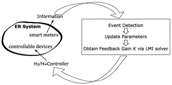
Figure 2.
The detailed procedures of the proposed mixed control approach.
From Figure 2, we can find that in iteration, parameters in are designed based on the information obtained from smart meters in previous interval, such that different events occur in the ER system can be properly tackled. Then, with system (8) and the control method, the controller can be obtained via convex optimization techniques. Thereby, the calculated controller is applied to the ER system for current time interval until the next iteration. By repeating such iteration, the long-term operation for the ER system can be achieved.
5. Simulation Results and Analysis
In this section, three case studies under different senarios are provided to show the efficacy and feasibility of the propsoed mixed control appraoch. The parameters for the considered ER system are generated based on parameter estimation methods from real-world engineering practice, given in Table 1.

Table 1.
System parameters.
In this paper, the LMI in Theorem 1 and the convex optimization problem in (11) are solved with the CVX toolbox of MATLAB R2018b. In this manner, the feedback gain for the mixed controller is obtained. According to (7), by minimizing the performance , the cumulative deviations of would be restricted. In this sense, in order to meet the demands under different scenarios, the weighting factors in are adjusted, such that different objectives could be achieved. For the simulation, Python packages, i.e., Numpy, Scipy, etc., are utilized to calculate the trajectory of the considered system. The effectiveness of the proposed approach is demonstrated via the results in the following scenarios.
5.1. Scenario I
The voltage regulation performance of the proposed controller is evaluated in this scenario. The parameters in are set to be , . The simulation results are shown in Figure 3.
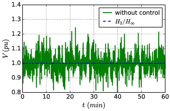
Figure 3.
Dynamics of the DC bus voltage deviation.
We can observe that in Figure 3, when the proposed mixed controller is applied to the ER system, dynamics of the DC bus voltage deviation are successfully restricted within a small range. Apparently, the voltage regulation performance under the mixed control approach is better than that without control (control output ). It is clear that the proposed control approach has satisfactory performance for the voltage stabilization target.
5.2. Scenario II
In this scenario, we focus on the rational utilization of FCs. As introduced above, the output power of FCs can be adjusted to match the power deviations of PVs, WTs and loads, such that the voltage regulation for the ER system could be achieved. However, unnecessary frequent power adjustment would lead to extra fuel consumption. Supposing that during the considered time period, a temporary fuel shortage of FCs is encountered. Thus, unnecessary frequent power adjustment in FCs is expected to be avoided. In order to maintain the normal operation of the ER system, the control for FC output power ought to be restricted. To achieve this target, the weighting factor for FCs in should be increased. More specifically, the parameters in are set to be . Additionally, in order to show the advantage of the proposed mixed control approach over the controller in Theorem 1, their performances are compared in the simulation results provided in Figure 4 and Figure 5.
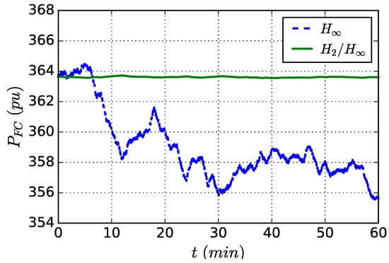
Figure 4.
Power output curves of fuel cells (FC) under mixed control and control methods.
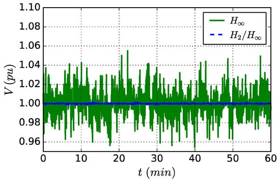
Figure 5.
Voltage deviation curves under mixed controller and controller.
It is easy to find that, under the mixed control, the fluctuations of the power dynamics for FCs in Figure 4 are smaller than that under control significantly. Additionally, the voltage deviation curves in Figure 5 indicate that the controller obtained from the proposed method has better voltage regulation performance than that of the approach in Theorem 1. Thus, in this scenario, the proposed mixed control approach is evaluated to be more flexible and satisfactory.
5.3. Scenario III
To further demonstrate the flexibility of the proposed method, a different scenario for the ER system is considered within a longer time period. Here, we take the assumption that within the considered three hours, part of the generators in MTs, DEGs, and FCs have experienced certain failure, which leads to a decrease in the adjustment range of total power outputs of MTs, FCs and DEGs. In order to ensure the normal operation of the ER system, the objectives for controller designing should also be adjusted accordingly. For the considered time period, the parameters for are set to be , .
To evaluate the efficacy of the proposed control approach, during the simulation, the results with controller are used for comparison. The power dynamics of MTs, FCs and DEGs in the considered three hours are illustrated in Figure 6, Figure 7 and Figure 8, respectively.
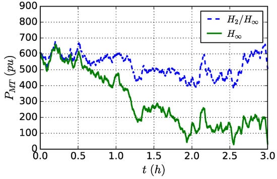
Figure 6.
Power dynamics of micro-turbines (MT) under mixed control and control schemes.
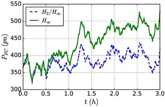
Figure 7.
Power dynamics of FCs under mixed control and control schemes.
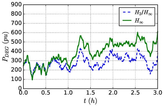
Figure 8.
Power dynamics of diesel engine generators (DEG) under mixed control and control schemes.
We can find that in Figure 6, the magnitude of output power deviation of MTs under the proposed mixed control scheme is smaller than that with the controller. In this sense, the impacts of failures occur in MTs are properly considered in the proposed approach. On the other hand, the controller might lead to system failure since such impacts are not fully considered.
Similar conclusions can be drawn for the control effect for FCs and DEGs. With Figure 7 and Figure 8, it is clear that the adjustments for power output of FCs and DEGs in the studied time period are successfully restricted according to system situations, i.e., failures occur in some of these devices. Additionally, from the dynamics of voltage deviation shown in Figure 9, we can find that the proposed mixed controller is able to take different system conditions into consideration as well as ensuring almost the same voltage regulation performances as the control scheme introduced in Theorem 1.
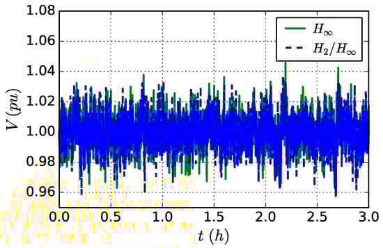
Figure 9.
Voltage deviation curves under mixed controller and controller.
Through the comparative analysis of the considered scenarios above, the mixed approach proposed in this paper is shown to be satisfactory. Additionally, by taking different constraints of the ER system into consideration, the proposed approach is able to achieve a more flexible management of the concerned devices, which leads to a steady and efficient operation of the ER system.
6. Conclusions
A typical ER system within an EI scenario has been investigated in this paper. To ensure the robust stability of the DC bus voltage and the rational energy managemnet strategy, ODEs are used to describe power dynamics of the considered ER system, and a mixed robust control problem is formulated and solved.
It is notable that voltage stabilization of the ER’s DC bus can be naturally obtained with a capacitor directly connected to the DC bus, which is regarded as possible future complementary work. Directly connecting the capacitor to the DC bus is a major improvement for the short-term transient stability of the ER system. Here, one of the interesting problems is that how long it takes for the DC bus stability to be achieved when supercapacitors are connected to DC bus. If an immediate system stabilization is desired to be achieved, instead of simply waiting for the natrural stabilization, how to design a class of control strategy is remain an open problem.
Currently, apart from joining some academic and engineering projects in the field EI, we are participating in drafting relevant national standards in China. For this paper, referencing to current grid regulations or grid code is beyond the scope. Indeed, for our future work, these issues shall be addressed.
Author Contributions
Conceptualization, H.H., C.H. and J.C.; Funding acquisition, J.C.; Methodology, H.H., Y.Q. and J.G.; Project administration, J.C.; Writing–original draft, H.H., Y.Q., J.G. and C.H.
Funding
This work was funded by the National Natural Science Foundation of China (Grant No. 61472200).
Conflicts of Interest
The authors declare no conflict of interest.
Nomenclature
| BES | Battery energy storage |
| DEG | Diesel engine generator |
| EI | Energy Internet |
| ER | Energy router |
| FC | Fuel cell |
| FES | Flywheel energy storage |
| LMI | Linear matrix inequality |
| MG | Microgrid |
| MT | Micro-turbine |
| ODE | Ordinary differential equation |
| PV | Photovoltaic |
| RES | Renewable energy source |
| WT | Wind turbine generator |
| Energy router 1 | |
| Energy router 2 | |
| System parameter of MTs | |
| System parameter of FCs | |
| System parameter of DEGs | |
| Uncertainties of factor | |
| Uncertainties of factor | |
| Uncertainties of factor | |
| Uncertainties of the reciprocal of time constants of PVs | |
| Uncertainties of the reciprocal of time constants of WTs | |
| Uncertainties of the reciprocal of time constants of loads | |
| Power transmission from to | |
| BES output power change | |
| DEG output power change | |
| FC output power change | |
| Load output power change | |
| MT output power change | |
| PV output power change | |
| FES output power change | |
| WT output power change | |
| System parameter of BESs | |
| System parameter of FESs | |
| Uncertainties of factor | |
| Uncertainties of factor | |
| Time constants of PVs | |
| Time constants of WTs | |
| Time constants of loads | |
| Time constants of MTs | |
| Time constants of DEGs | |
| Time constants of FCs | |
| Time constants of BESs | |
| Time constants of FESs | |
| Control input signal of MTs | |
| Control input signal of FCs | |
| Control input signal of DEGs | |
| DC bus voltage deviation | |
| Change of solar irradiation | |
| Power of wind | |
| Load power disturbances |
Appendix A
According to [41], the basics of is briefly given here. In control theory, (i.e., H-infinity) methods are used to synthesize controllers, such that system stabilization with guaranteed performance is achieved. When method is applied, such system stabilization problem can be formulated as a mathematical optimization problem and one is required to find the controller which solves this control problem. For the term , the letter stands for Hardy space, and the symbol stands for infinity norm. The classic control therory is investigated in frequency domain and the moderen control therory is studied in time domain. In this paper, a time domain approach is applied to solve the formulated problem. The detailed definition for our specified control problem is given in Definition 2.
Appendix B
The coefficient matrices and in system (3) are presented with (A1)–(A4).
The coefficient matrix is presented with (A5)
References
- Rifkin, J. The Third Industrial Revolution: How Lateral Power Is Transforming Energy, the Economy, and the World; Palgrave Macmillan: New York, NY, USA, 2013; pp. 31–46. [Google Scholar]
- Cao, J.; Hua, H.; Ren, G. Energy Use and the Internet; The SAGE Encyclopedia of the Internet; SAGE Publications: Delhi, India, 2018; pp. 344–350. [Google Scholar] [CrossRef]
- Madhja, A.; Nikoletseas, S.; Raptopoulos, C.; Tsolovos, D. Energy Aware Network Formation in Peer-To-Peer Wireless Power Transfer. In Proceedings of the ACM International Conference on Modeling, Analysis and Simulation of Wireless and Mobile Systems, Malta, 13–17 November 2016; pp. 43–50. [Google Scholar]
- Zhong, Q.C.; Weiss, G. Static synchronous generators for distributed generation and renewable energy. In Proceedings of the Power Systems Conference and Exposition, Seattle, WA, USA, 15–18 March 2009; pp. 1–6. [Google Scholar]
- Aalami, H.A.; Nojavan, S. Energy storage system and demand response program effects on stochastic energy procurement of large consumers considering renewable generation. IET Gener. Transm. Distrib. 2016, 10, 107–114. [Google Scholar] [CrossRef]
- Jane, D.; Nitin, J. Supply chain integration, product modularity, and market valuation: Evidence from the solar energy industry. Prod. Oper. Manag. 2013, 22, 1494–1508. [Google Scholar]
- Zhang, W.; Hua, H.; Cao, J. Short term load forecasting based on IGSA-ELM algorithm. In Proceedings of the 1st IEEE International Conference on Energy Internet, Beijing, China, 17–21 April 2017; pp. 296–301. [Google Scholar]
- Zhang, W.Q.; Zhang, X.Y.; Huang, S.W.; Xia, Y.K.; Fan, X.C.; Mei, S.W. Evolution of a transmission network with high proportion of renewable energy in the future. Renew. Energy 2016, 102, 372–379. [Google Scholar] [CrossRef]
- Kuang, Y.; Zhang, Y.; Zhou, B.; Li, C.; Cao, Y.; Li, L. A review of renewable energy utilization in islands. Renew. Sustain. Energy Rev. 2016, 59, 504–513. [Google Scholar] [CrossRef]
- Qian, L.P.; Zhang, Y.J.A.; Huang, J.; Wu, Y. Demand response management via real-time electricity price control in smart grids. IEEE J. Sel. Areas Commun. 2013, 31, 1268–1280. [Google Scholar] [CrossRef]
- Zhang, Y.; Chen, Z.; Cai, Z.; Licheng, L.I.; Song, W. New generation of cyber-energy system:energy internet. Electr. Power Autom. Equip. 2016, 36, 1–7. [Google Scholar]
- Guo, C.; Wang, Z.; Jian-Wei, J.I.; Fang-Jing, M.A.; Management, D.O. Model simulation of electricity characteristics in power user data based on data mining. Comput. Simul. 2016, 33, 447–450. [Google Scholar]
- Shenhang, Y.U.; Ying, S.; Niu, X.; Zhao, C. Energy internet system based on distributed renewable energy generation. Electr. Power Autom. Equip. 2010, 30, 104–108. [Google Scholar]
- Shah, S.T.; Choi, K.W.; Hasan, S.F.; Chung, M.Y. Energy harvesting and information processing in two-way multiplicative relay networks. Electron. Lett. 2016, 52, 751–753. [Google Scholar] [CrossRef]
- Chen, Z.X.; Zhang, Y.J.; Cai, Z.X.; Li, L.C.; Liu, P. Characteristics and technical challenges in energy Internet cyber-physical system. In Proceedings of the Pes Innovative Smart Grid Technologies Conference Europe, Torino, Italy, 26–29 September 2017; pp. 1–5. [Google Scholar]
- Ma, Y.; Wang, X.; Zhou, X.; Gao, Z. An overview of energy routers. In Proceedings of the 29th Chinese Control and Decision Conference, Chongqing, China, 28–30 May 2017; pp. 4104–4108. [Google Scholar]
- Huang, A.Q.; Crow, M.L.; Heydt, G.T.; Zheng, J.P.; Dale, S.J. The Future Renewable Electric Energy Delivery and Management (FREEDM) System: The Energy Internet. Proc. IEEE 2010, 99, 133–148. [Google Scholar] [CrossRef]
- Xu, Y.; Zhang, J.H.; Wang, W.Y. Energy router: Architectures and functionalities toward energy internet. In Proceedings of the 2011 IEEE International Conference on Smart Grid Communication, Brussels, Belgium, 17–20 October 2011; pp. 31–36. [Google Scholar]
- Geidl, M.; Koeppel, G.; Favre-Perrod, P.; Klockl, B.; Andersson, G.; Frohlich, K. Energy hubs for the future. Power Energy Mag. IEEE 2007, 5, 24–30. [Google Scholar] [CrossRef]
- Fu, W.; Song, T.; Wang, S.; Wang, X. Dynamic frequency scaling architecture for energy efficient router. In Proceedings of the Eighth ACM/IEEE Symposium on Architectures for Networking & Communications Systems, Austin, TX, USA, 29–30 October 2012. [Google Scholar]
- Zhang, J.; Wang, W.; Bhattacharya, S. Architecture of solid state transformer-based energy router and models of energy traffic. In Proceedings of the Innovative Smart Grid Technologies, Washington, DC, USA, 16–20 January 2012. [Google Scholar]
- Junwei, C.; Kun, M.; Jiye, W.; Mingbo, Y.; Zhen, C.; Wenzhuo, L.I. An energy internet and energy routers. Sci. Sin. (Inf.) 2014, 44, 714. [Google Scholar]
- Zhao, T.; Wang, G.; Bhattacharya, S. Voltage and power balance control for a cascaded H-bridge converter-based solid-state transformer. IEEE Trans. Power Electron. 2013, 28, 1523–1532. [Google Scholar] [CrossRef]
- Bifaretti, S.; Zanchetta, P.; Watson, A.; Tarisciotti, L.; Clare, J.C. Advanced power electronic conversion and control system for universal and flexible power management. IEEE Trans. Smart Grid 2011, 2, 231–243. [Google Scholar] [CrossRef]
- Zhao, T.F. Design and Control of a Cascaded H-Bridge Converter Based Solid State Transformer (SST); North Carolina State University: Raleigh, NC, USA, 2010; pp. 20–21. [Google Scholar]
- Huber, J.E.; Kolar, J.W. Common-mode currents in multi-cell solid-state transformers. In Proceedings of the Power Electronics Conference (ECCE Asia), Hiroshima, Japan, 18–21 May 2014. [Google Scholar]
- Grider, D.; Das, M.; Agarwal, A. 10 kV/120 A SiC DMOSFET half H-bridge power modules for 1 MVA solid state power substation. In Proceedings of the IEEE Electric Ship Technologies Symposium (ESTS), Alexandria, VA, USA, 10–13 April 2011. [Google Scholar]
- Wang, R.; Wu, J.; Qian, Z.; Lin, Z. A graph theory based energy routing algorithm in energy local area network. IEEE Trans. Ind. Inf. 2017, 13, 3275–3285. [Google Scholar] [CrossRef]
- Hua, H.; Qin, Y.; Hao, C.; Cao, J. Stochastic optimal control for energy Internet: A bottom-up energy management approach. IEEE Trans Ind. Inf. 2018. [Google Scholar] [CrossRef]
- Erol-Kantarci, M.; Sarker, J.H.; Mouftah, H.T. Energy routing in the smart grid for delay-tolerant loads and mobile energy buffers. In Proceedings of the 2013 IEEE Symp. on Computers and Communications, Split, Croatia, 7–10 July 2013; pp. 149–154. [Google Scholar]
- Hambridge, S.; Huang, A.Q.; Yu, R. Solid state transformer (SST) as an energy router: Economic dispatch based energy routing strategy. In Proceedings of the 2015 IEEE Energy Conversion Congress and Exposition, Montreal, QC, Canada, 20–24 September 2015; pp. 2355–2360. [Google Scholar]
- Han, X.; Yang, F.; Bai, C.; Xie, G.; Ren, G.; Hua, H. An open energy routing network for low-voltage distribution power grid. In Proceedings of the 1st IEEE International Conference on Energy Internet, Beijing, China, 17–21 April 2017; pp. 320–325. [Google Scholar]
- Hua, H.; Cao, J.; Yang, G.; Ren, G. Voltage control for uncertain stochastic nonlinear system with application to energy Internet: Non-fragile robust H∞ approach. J. Math. Anal. Appl. 2018, 463, 93–110. [Google Scholar] [CrossRef]
- Liu, Y.; Fang, Y.; Li, J. Interconnecting microgrids via the energy router with smart energy management. Energies 2017, 10, 1297. [Google Scholar]
- Yi, P.; Zhu, T.; Jiang, B.; Jin, R.; Wang, B. Deploying energy routers in an energy Internet based on electric vehicles. IEEE Trans. Veh. Technol. 2016, 65, 4714–4725. [Google Scholar] [CrossRef]
- Hua, H.; Hao, C.; Qin, Y.; Cao, J. A class of control strategies for energy Internet considering system robustness and operation cost optimization. Energies 2018, 11, 1593. [Google Scholar] [CrossRef]
- Hua, H.; Qin, Y.; Cao, J. Coordinated frequency control for multiple microgrids in energy Internet: A stochastic H∞ approach. In Proceedings of the 2018 IEEE PES Innovative Smart Grid Technologies Asia, Singapore, 22–25 May 2018; pp. 810–815. [Google Scholar]
- Bevrani, H.; Feizi, M.R.; Ataee, S. Robust frequency control in an islanded microgrid: H∞ and μ-Synthesis Approaches. IEEE Trans. Smart Grid 2016, 7, 706–717. [Google Scholar] [CrossRef]
- Xu, S.; Chen, T. Robust H∞ control for uncertain stochastic systems with state delay. IEEE Trans. Autom. Contr. 2002, 47, 2089–2094. [Google Scholar]
- Chen, G.; Yang, M.; Yu, L. Mixed H2/H∞ optimal guaranteed cost control of uncertain linear systems. J. Syst. Sci. Inf. 2004, 2, 409–416. [Google Scholar]
- Zhou, K.; Doyle, J.C.; Glover, K. Robust and Optimal Control; Prentice Hall: Englewood Cliffs, NJ, USA, 1995. [Google Scholar]
© 2019 by the authors. Licensee MDPI, Basel, Switzerland. This article is an open access article distributed under the terms and conditions of the Creative Commons Attribution (CC BY) license (http://creativecommons.org/licenses/by/4.0/).