Article

Profitability Analysis and Capital Cost Estimation of a Thermochemical Energy Storage System Utilizing Fluidized Bed Reactors and the Reaction System MgO/Mg(OH)2

1
Institute for Energy Systems and Thermodynamics, TU Wien, Getreidemarkt 9, A-1060 Vienna, Austria
2
Institute of Chemical, Environmental and Bioscience Engineering, TU Wien, Getreidemarkt 9, A-1060 Vienna, Austria
3
AMMAG GmbH, Dahlienstraße 11, A-4623 Gunskirchen, Austria
*
Author to whom correspondence should be addressed.
Energies 2019, 12(24), 4788; https://doi.org/10.3390/en12244788
Submission received: 24 November 2019 / Revised: 10 December 2019 / Accepted: 11 December 2019 / Published: 16 December 2019
(This article belongs to the Special Issue Development in Thermochemical Energy Storage)

Abstract

:
The storage of industrial waste heat through thermochemical energy storage (TCES) shows high potential to reduce the dependency on fossil fuels. In this paper the capital cost investment of a TCES system utilizing fluidized bed reactors and the reaction system MgO/Mg(OH) 2 is estimated and a profitability analysis is performed. The study estimate is based on a simulation study that considers the mass and energy balance of the proposed preliminary heat storage and release processes utilizing fluidized bed reactors. Furthermore, transport, operation and maintenance as well as utility costs were estimated in order to evaluate the profitability of the system. It is concluded that for the selected boundary conditions, the specific investment costs per kW stored heat are approximately 900 €/kW and that the systems should not be installed at sites where less than around 5 MW of waste heat are available. Finally, a sensitivity analysis was conducted, to identify the key process and economic parameters critical for a positive net present value.

1. Introduction

Industrial waste heat recovery is considered as an efficient method to counteract against the ever increasing energy demand and also to reduce the carbon footprint [1]. In many processes, heat is produced as a by-product that is not required on site. An example where high heat recovery potential exists, are gas compressor stations. These facilities are used to maintain the gas pressure in natural gas pipelines. Typically they are placed every 100– 200 km along the pipeline and consist of a gas turbine that is fuelled by a portion of the transported gas stream driving a gas compressor [2]. The temperature of the arising exhaust gases is above 645 K. The available waste heat in the USA is estimated to be on average 610 TJ/day, which has the potential to avoid emissions of 47.000 metric tonnes of CO 2 eq / day , [3].
Through thermochemical energy storage (TCES) the decentralized produced heat can be stored by means of reversible chemical reactions and transported to sites with heat demand. In the schematically illustrated TCES concept of Figure 1, the heat is stored and released by means of reversible gas-solid reaction systems of the type:
ν A A ( s ) + Δ H R ν B B ( s ) + ν C C ( g ) .
During the charging process, the heat is stored in terms of an endothermic reaction, releasing the gaseous reactant. The thermochemical material (TCM) is subsequently transported or stored on site. Discharge occurs when the gaseous reaction partner is fed to the TCM, triggering the exothermic reaction and releasing the stored heat.
Amongst the existing thermal energy storage (TES) technologies [4,5,6], only TCES is site independent. It also enables storage at ambient temperature, which leads to a nearly loss-free storage process. Furthermore it shows higher gravimetric and volumetric energy density compared to latent or sensible heat storage systems [7,8,9,10,11,12,13].
A lot of effort has been put into the characterization and improvement of metal oxide/hydroxide systems [14,15,16,17,18,19] as well as the process integration and application of TCES-systems [20,21,22,23,24,25,26]. Also, the reaction kinetics which are important for the precise modelling of reactors [27,28] have been identified for various materials [18,29,30,31,32].
An essential problem that has not been addressed in literature elaborately is the capital cost estimation and economic feasibility of TCES-concepts. In general, accurately estimating any investment of new plants is a great challenge due to the lack of comparable data. Yet it is possible to perform a study estimate based on a process design with a mass and energy balance and equipment sizing. In this work a TCES-process, utilizing fluidized bed reactors and the reaction system MgO/Mg(OH) 2 for waste heat recovery of a gas compressor station is proposed. The total capital investment based on the overall factor method of Lang [33], and the operating expenses and earnings, are calculated. In order to determine, if the investment is profitable, the net present value (NPV) of the proposed plant is calculated. Also a sensitivity analysis by varying key process parameters is performed to evaluate the effect of fluctuating values on the process and to determine the minimum requirements that yield a positive NPV.

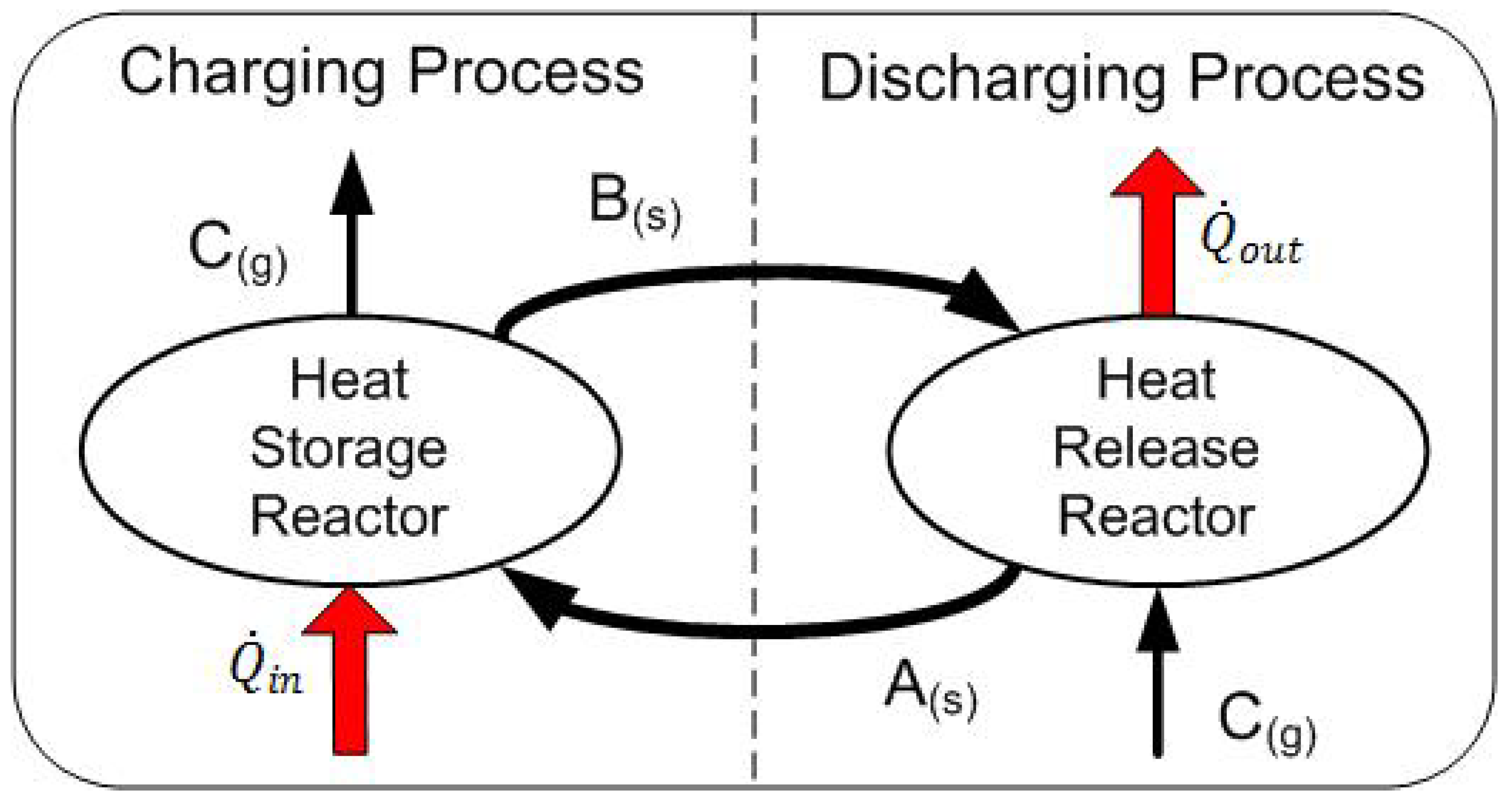
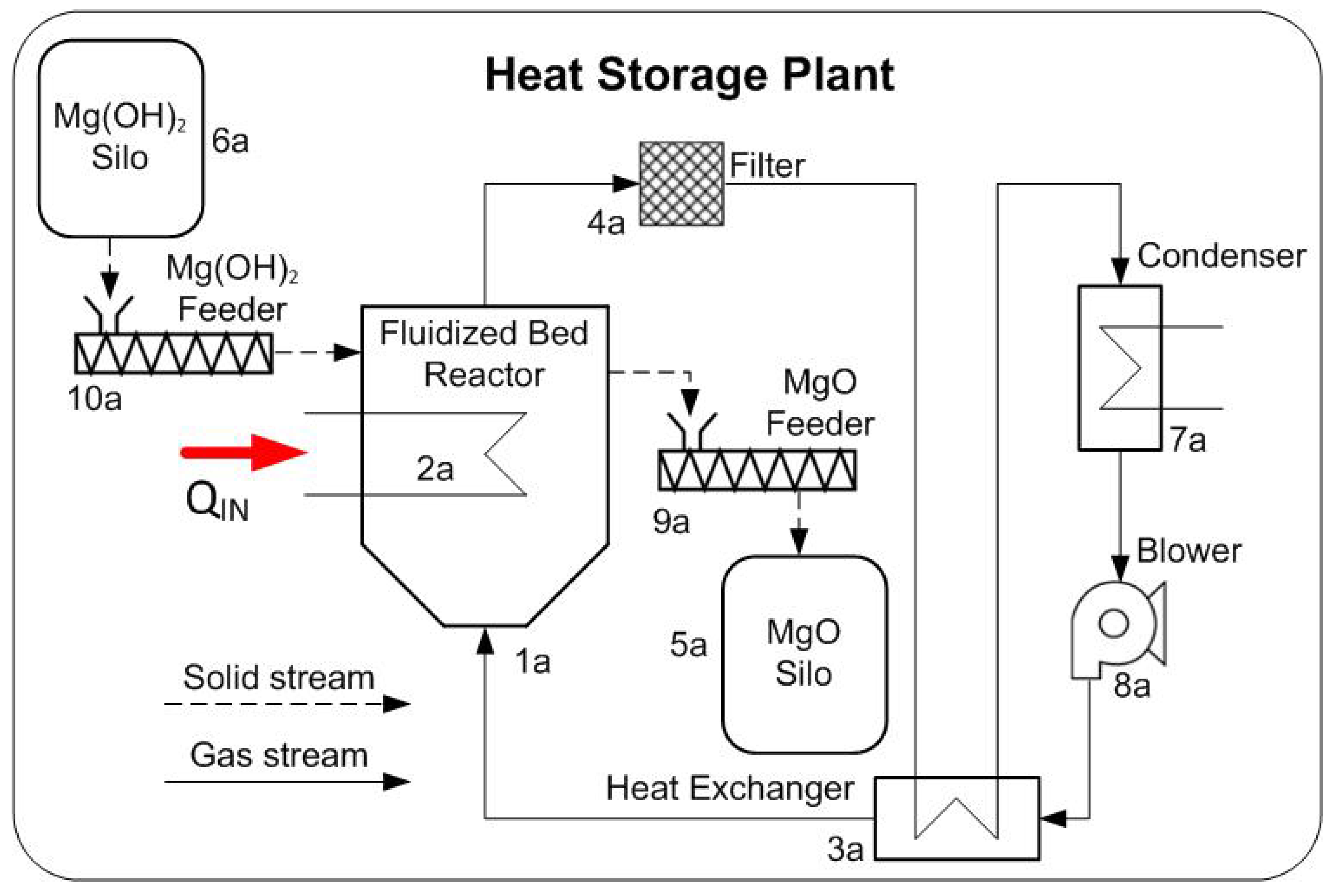
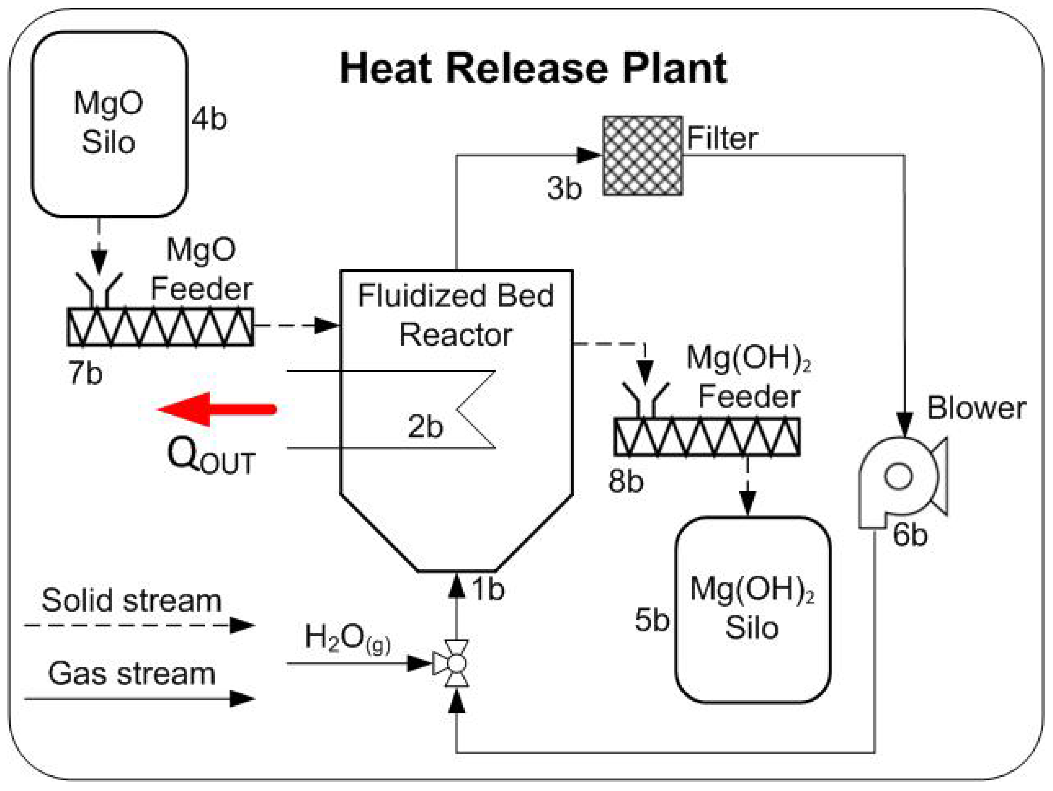
2. System Description

The reaction system MgO / Mg ( OH ) 2 was chosen for the study as it is well established and often considered for TCES-applications. The materials are available as intermediate size particles (Geldart AB or B). The reaction shows good reversibility at ambient pressure and a theoretical storage capacity of 380 kWhm−3. Furthermore the materials are widely available at a competitive price. On the other hand the reactivity of the reaction is low and the materials show low thermal conductivity [9].
From the different available continuous reactor types for gas-solid reactions [34], fluidized bed reactors (FBR) were selected for this application, because they offer constant temperature distribution in the bed, high heat and mass transfer rates and are capable of handling large material flows [35].
The proposed heat storage and release plants are illustrated in Figure 2 and Figure 3 respectively. The waste heat from the gas compressor stations is transferred into the heat storage reactor via the internal heat exchanger tubes. The feeders ensure the continuous operation, by supplying and removing TCM from the reactors from and to the storage bins. The particle residence time is adjusted by the particle feed rate and the role of the bins is to ascertain the independent plant operation for a defined period of time, thus decoupling supply and demand. The reactors are dimensioned so that they can store 5.5 MW operating at atmospheric conditions. The temperature of the waste heat is assumed to be 450 °C.
The main difference between the heat storage and release plant, is that in the storage plant, the water content of the fluidization gas has to be removed from the inert gas stream in order for the dehydration reaction to occur under advantageous kinetic conditions. The sensible heat from the stream is recovered in the heat exchanger and the water is subsequently removed in the condenser. A recuperator is not required in the heat release plant because it is not required to remove any components from the fluidization gas. The steam portion that is absorbed by the reaction is replenished by the injection of the on-site available steam.
Flegkas et al. [28] discussed extensively the impact of the availability of steam on the heat release site. It is concluded that it plays a major role for the overall feasibility of TCES systems. Due to the reaction enthalpy range of the TCM, it is not profitable to use the released heat for the supply of the the required steam mass flow in order to uphold the exothermic reaction for the reaction system MgO / Mg ( OH ) 2 . Hence, without an external steam supply, TCES systems would be rendered inefficient and uneconomical. Therefore it is assumed that steam is available on the heat release site and that no additional charges occur for its usage. This would also be the case in technological sectors where low grade heat, sufficient for the supply of steam arises, hence enabling the implementation of a thermochemical heat pump system.

3. Economic Analysis

3.1. Capital Cost Estimation

The total capital investment estimation is based on a preliminary process design, hence the method initially developed by Lang [33] was used for the assessment. This method requires a complete process design with solved mass and energy balances, as well as estimations about the size of the equipment and yields the total capital investment.
The free on board (f.o.b.) purchase costs C P of the most widely used process equipment, required for the calculation of the total capital investment, can be extracted from a plethora of published literature [33,36,37], either from a graph or by an equation that requires a size parameter S for each component. These values have to be adjusted to the current date, by the ratio of the latest cost index I c (for May 2017, I c = 567.3 , [38]) to the cost index of the year in which the cost equation was published I B a s e . The sum of the updated purchased costs, multiplied by 1.05 to account for the delivery of the equipment, amounts to the total f. o. b. costs.
In order to obtain the total capital investment C T C I , including an estimate of the working capital at 15% of the purchased equipment costs, an appropriate Lang factor f L must be taken into account. This factor takes into account additional direct and indirect costs like the installation of the equipment, piping, instrumentation and engineering as well as construction expenses. The recommended Lang factor according to Peters et al. [37] for solid processing plants is 4.67 . Additionally site dependent costs have to be included in the calculation. For Western Europe, the investment site factors F I S F is 1.2 [33]. The capital investment must also consider the costs of the initially acquired thermochemical material C T C M . The material mass results from the the volume of the TCM storage bins. Finally the total capital investment amounts to:
C T C I = 1.05 f L F I S F i I c , i I B a s e , i C P , i + C T C M .
The error in a cost estimate is determined by the degree of design detail. In the presented study, based on the available knowledge about the utilized equipment, the probable accuracy of the estimates is up to ± 30 % .

3.2. Component Design
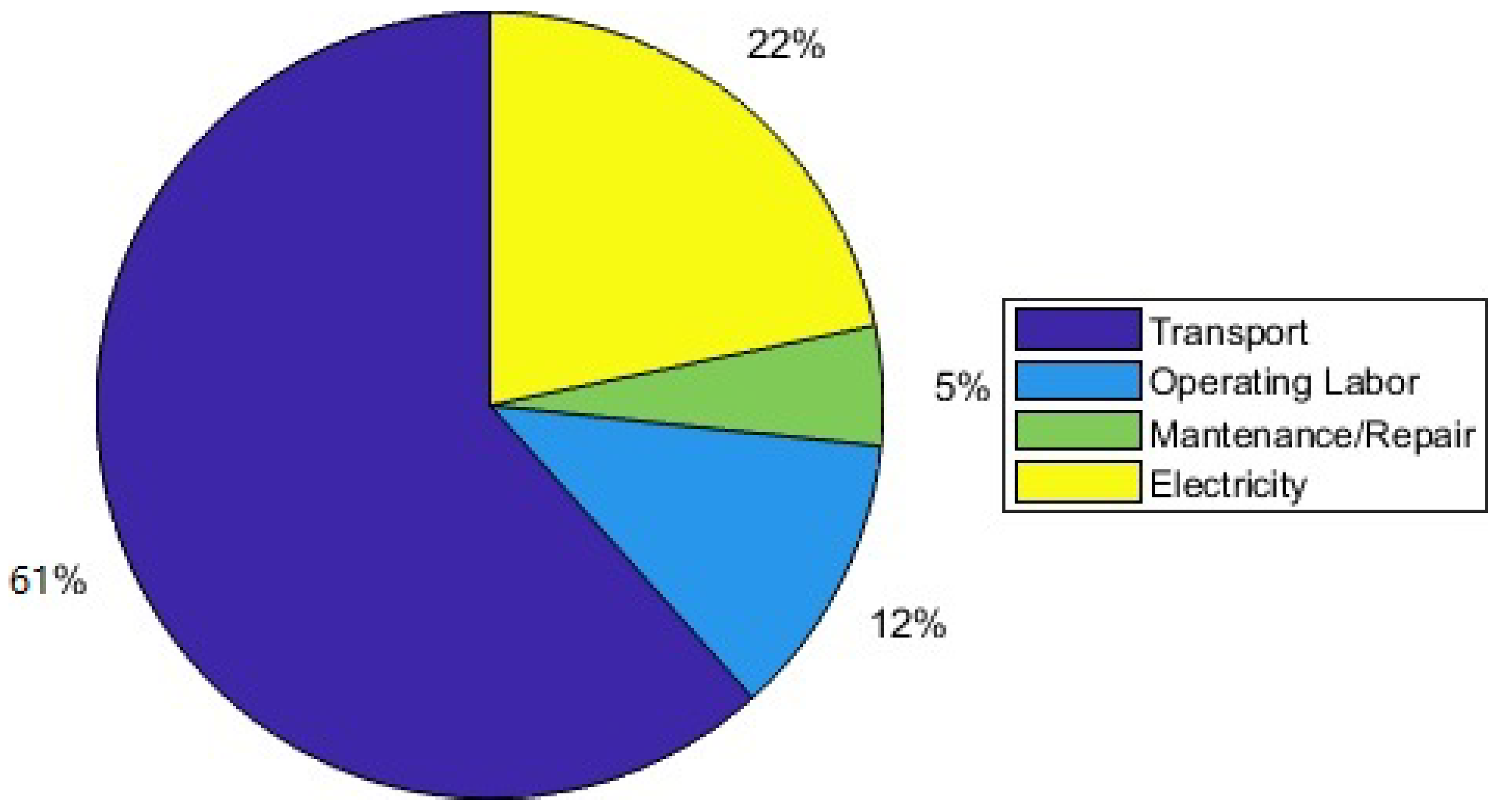
Reactor
No capital cost estimations of atmospheric operating fluidized bed reactors are available in literature. Nonetheless the component costs can be calculated as in the case of a pressure vessel since it operates under similar heat and atmospheric conditions [36]. The relevant size parameters for this component is the reactor volume as well as the total reactor mass. In this application the bed volume, heat exchanger volume and the freeboard need to be taken into account. The operating temperature of the storage and release reactor is 330 °C and 130 °C respectively, in order to provide favourable kinetic conditions for the reactions.
In order to determine the volume of the reactor V R , the absorbed or released heat flow Q ˙ defines the required solid material stream m ˙ s :
Q ˙ = Δ H R m ˙ s .
The particle residence time τ p yields the particle mass M T C M inside the reactor:
M T C M = τ p m ˙ s .
The required residence time for full conversion is ruled by the kinetics of the reaction. A detailed description of its calculation in FBR, regarding the particle residence time distribution is provided by Flegkas et al. [28].
The bed volume V b e d can be obtained through the particle bulk density ρ b u l k :
V B e d = M T C M ρ b u l k .
Additionally the volume of the in bed heat exchanger V H E X has to be taken into account in order to yield the total volume of the storage reactor. The heat transfer area of the in bed heat exchanger A I B H E X is calculated with:
Q ˙ = k I B H E X A I B H E X Δ θ m , I B H E X ,
where Δ θ m , I B H E X is the the mean temperature difference between the heat transfer fluid and the reactor bed. Typical values for the heat transfer coefficient k I B H E X in fluidised bed reactors lie between 200– 400 W/m2K [35]. Since no cost function for in-bed heat exchangers is available in literature, a correlation for shell-and-tube heat exchangers, provided by Reference [33] is used.
The freeboard over the bed is assumed to amount to 50 % of the bed and in-bed heat exchanger volume. Finally, the total volume of the reactor is given by:
V R = 1.5 ( V b e d + V I B H E X ) .
Assuming a carbon steel cylindrical reactor with an inner diameter of 5 m and a wall thickness of 20 mm, geometrical calculations yield the reactor mass M R .
Filters, Heat Exchangers and Blowers
The reactor size as well as the TCM properties determine the required gas stream through the minimum fluidization velocity u m i n , f l . The correlation proposed by Wen et al. [39] is used for its calculation:
u m i n , f l = μ ρ g d p ( 33.7 2 + 0.0408 A r 33.7 ) ,
where d p is the diameter of the particles, A r the Archimedes number, μ the dynamic viscosity and ρ g the density of the fluidization gas respectively. If the reactor cross-section A C S is given, it returns the required gas mas stream m ˙ g , which is the size factor of the filters, the heat exchangers and blowers. For this study it is assumed that the reactors operate at twice the minimum fluidization velocity, in order to ensure a bubbling bed without increasing the auxiliary energy required for the fluidization gas blowers.
m ˙ g = 2 ρ g u m i n , f l A C S .
The fluidization velocity and subsequently the gas bubbles inside the reactor bed, have an impact on the mixing conditions, temperature uniformity and in-bed heat transfer coefficients. In general higher fluidization velocities amplify these phenomena [28].
The heat transfer area A H E X of the heat exchanger and condenser is determined according to Equation (6). Typical values for the heat transfer coefficient k H E X of gas-gas (pressure ≈ 1 bar) shell-and-tube heat exchangers lie between 5– 35 W/m2K and for liquid-gas condensers between 15– 70 W/m2K [40].
The capital costs of the blowers, including an electric motor drive, can be determined by calculating the the blower power through the gas mass stream under the assumption of typical pressure drops within the atmospheric operating fluidized bed reactors. The mechanical efficiency of the blowers is set to η m = 0.75 .
Bins and Feeders
The produced solid mass stream of the reactors is the sizing factor for the screw feeders. It also determines the required bin volume V B i n in order to provide the reaction material for a given period of time τ S t without resupply:
V B i n = m ˙ s τ S t .
The bins are dimensioned for a supply period of 2 days.

3.3. Expenses

Transport Costs
Since the heat storage and heat release plants are located at different sites, the TCM has to be transported between the sites after each release and storage process. Transportation via road is chosen. The transportation costs C T r are determined according to a calculation method for freight traffic, published by the German federal ministry of transportation [41].
The correlation considers fuel C F , variable C Var and fixed C F i x transportation costs and personnel costs C P e r as a function of the travel distance T D and travel time T T between the sites. The total mass of transported TCM, yields the required amount of journeys per annum assuming a transportation load of 24 t/journey. It is calculated by the product of the operating hours per annum and the produced solid mass stream of the heat release plant, which is higher than the mass stream of the heat storage plant, due to the higher molecular weight of the Mg ( OH ) 2 compared to the MgO .
C T r = T D ( C F + C V a r ) + ( 1.2 T T + 1.5 ) C P e r + 1.2 T T C F i x .
The equation is simplified because it is assumed that no costs from the usage of freight containers and no additional infrastructure usage like tunnels or bridges arise. Furthermore it is assumed that no toll charges apply on the route.
Operating Labor and Maintenance
Both the heat storage and the heat release plants have to be located next to existing industrial sites. In the considered case, the waste heat provided by a gas compressor station is stored and released into a district heating network. This means that no dedicated personnel is required for the operation of the thermochemical plants, hence it is assumed personnel is only present for 30% of the operation time T O p . Hence with a given workers wage C W a g e the operating labour costs C O for the two plants are:
C O = 2 × 0.3 T O p C W a g e .
Annual costs for equipment maintenance and repairs can be determined as a percentage (2–20%) of the equipment costs [37], here a percentage value of 10% was assumed. Additionally the costs for the operating supplies is about 15% of the total cost for maintenance and repairs. Consequently the total maintenance costs C M amount to:
C M = 1.15 × 0.10 i I c , i I B a s e , i C P , i .
The electricity costs mainly consist of the required blower power. The direct power requirements are increased by a factor of 1.25 as suggested by Peters et al. [37], in order to cover the supply for lighting, motors and other various process-equipment demands. The price of electricity is set to 0.042 €/kWh. No additional costs for the supply of steam are considered, because the heat release site is assumed to be at locations, where either steam or low grade heat is available.

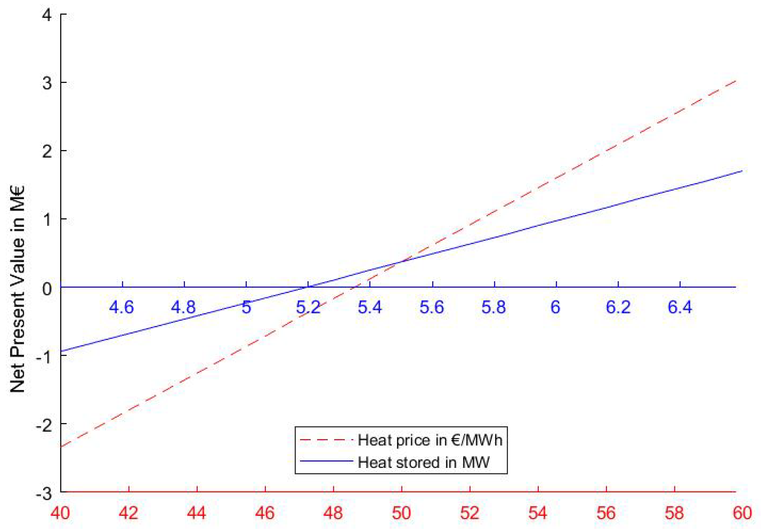
3.4. Income and Economic Performance Evaluation

The net earnings p.a. E t of the process are determined by the amount of the produced heat of the heat release plant. It was extensively discussed in References [23,28] that it is not possible to recover the whole amount of the stored heat. This is attributed to process limitations like particle pre-heating and not utilizing the sensible heat of the solids after they exit the reactor. Therefore a round trip efficiency η r t , which is the fraction of the released heat per the initially stored heat is considered in the earnings equation:
E t = η r t C H T O p Q ˙ ,
where C H is the price charged per M W h . The value range of η r t has been extensively discussed in Reference [23]. For the considered system, η r t is set to 70 %.
As an indicator of the plant profitability the net present value (NPV) is calculated:
N P V = C T C I + t = 1 t = n E t A t ( 1 + i / 100 ) t ,
where A t are the total operating expenses, consisting mainly of the transport, labour and maintenance costs. The value of the NPV, depends greatly upon the assumed interest rate i and service life t, which are set to to 7.5% and 15 years respectively. In order for the investment to be profitable the NPV has to be positive.

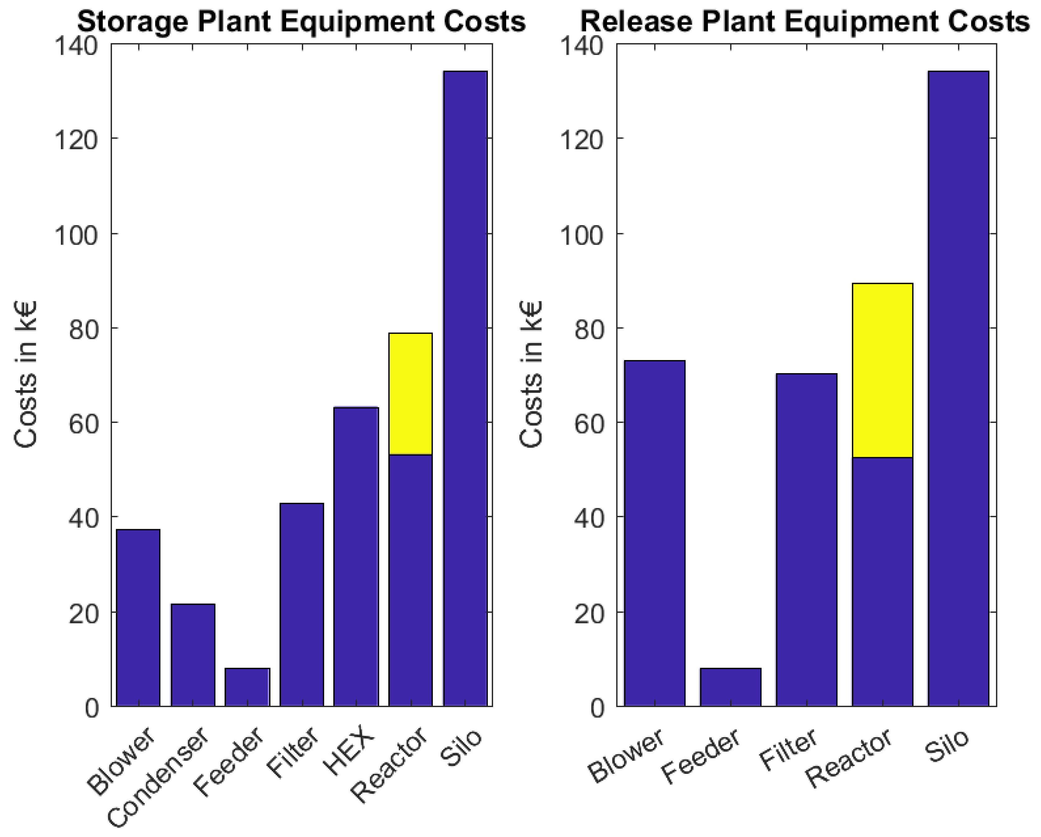
4. Results and Discussion

Table 1 summarizes the key process and economic parameters that were used for the estimation of the investment costs. The results for the total capital investment as well as operating costs p.a. and income p.a. are outlined in Table 2. Since the NPV is positive, the investment would be profitable under the assumptions that were made.
The purchased equipment costs of the storage and release plants are depicted in Figure 4 and are listed alongside the the size factors of the process components for the heat storage and the heat release plant in Table 3 and Table 4, respectively. The two most expensive components are the reactors including the in-bed heat exchangers (marked in yellow in the bar graph) and the solid storage bins, which are dimensioned so that they provide material for the process for 2 days without supply. The total investment costs of the two plants and the initial material costs are depicted in Table 1. It is evident that although fewer components are utilized in the heat release than in the storage plant, the total equipment costs are nearly equal. This can be attributed to the fact that the particle density of the MgO is higher than that of Mg ( OH ) 2 , leading to higher fluidization gas streams which result in higher blower and filter costs.
The operating costs are illustrated in Figure 5. Transport costs make up the biggest portion, namely 61%, operation and maintenance costs amount to 17% while electricity costs constitute the remaining 22%. This means that the profitability of the process greatly depends upon both the distance between the hydration and dehydration plant and the time that the truck requires to transport the TCM between the two locations. Ideally both plants would be located on the same site, thus no transport costs would arise.
In order to store the assumed amount of heat, a mass flow of 2.74 kg/s Mg ( OH ) 2 is required. This amount of TCM has to be transported between the two sites resulting into approximately 9500 truck rides per year. In other words, at least 4 trucks, which make multiple rides per day, are required to keep the operation running. As a consequence about 250 tons of CO 2 eq , or 8.1 gCO2/kWh of recovered heat, are produced per annum. Taking into account the total capital cost investment under the assumed conditions and the amount of the produced heat per annum, the costs for one kWh of heat are 0.16 €.
A critical property of TCM that also has to be considered, is the cycle stability. Since the particle stay for two days in each of the four solid bins it is concluded that the TCM must withstand approximately 40 cycles per annum.

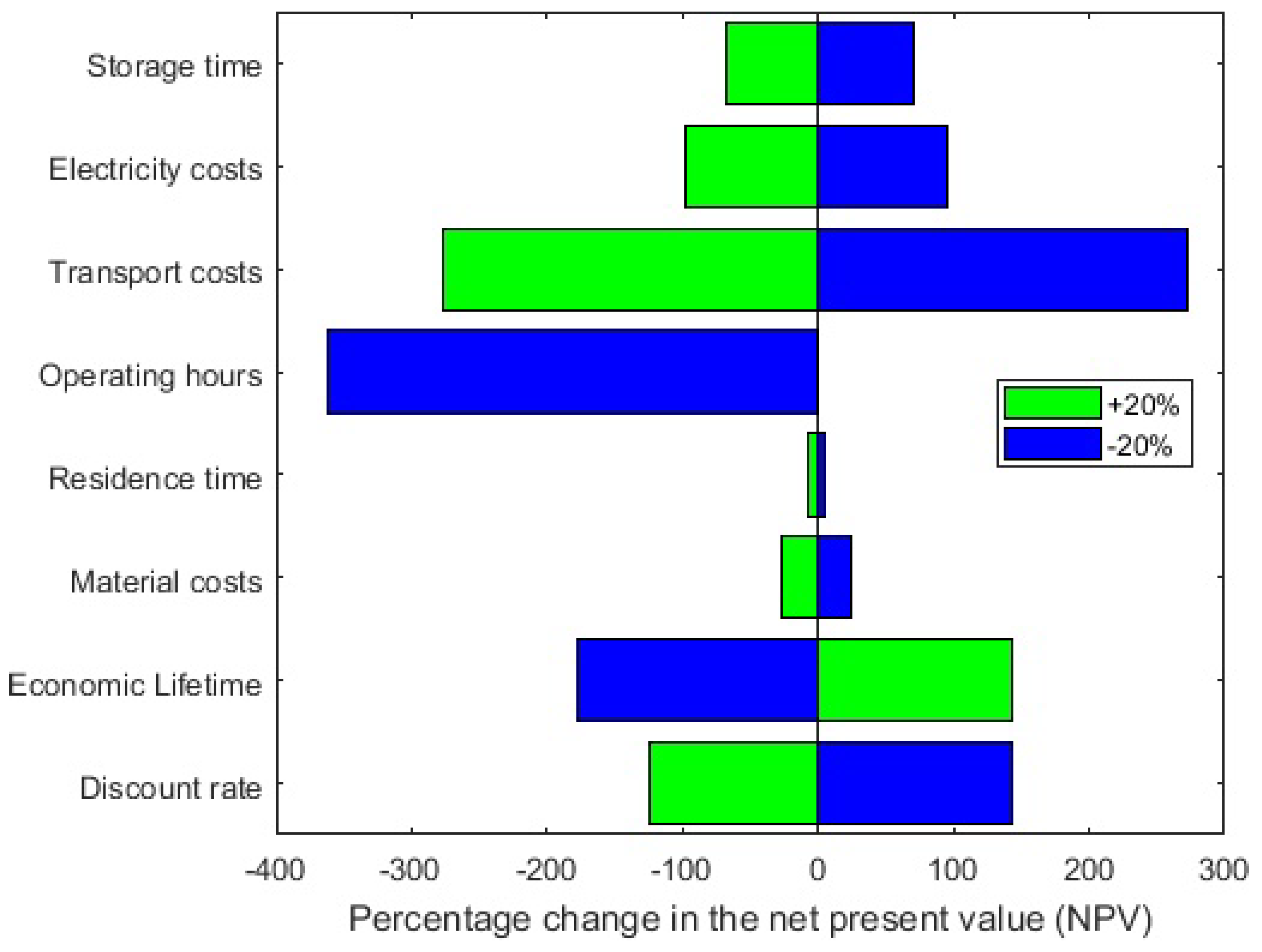
Sensitivity Analysis

In order to evaluate the profitability of a thermochemical energy storage concept with the reaction pair MgO Mg ( OH ) 2 , a sensitivity analysis was performed to rank the influence of key economic and process parameters.
The study showed that the dominating parameters that influence the economic feasibility of the TCES system are the amount of heat that is available for storage, the process efficiency and the price at which the heat can be sold. The last two factors have the same impact on the earnings as stated in Equation (14). The minimum value of these parameters that is required to yield a positive NPV under the given conditions are depicted in Figure 6. These values should be seen as the rough lower limits at which TCES systems can be installed profitably.
Furthermore, the impact of less influential parameters is depicted in Figure 7. From the listed parameters, the transport costs and the operating hours have the biggest impact on the NPV.
The plant is assumed to operate 8000 h per annum, a reduction of this time, would lead to a decrease of the NPV rendering the system uneconomic. An increase of the transport costs of 20% has a similar effect. Similarly, reducing or even omitting the transport costs, greatly benefits the feasibility of the TCES-system. This would be the case for example, if the heat release and storage plant are located on the same site.
Economic parameters like the real interest rate and economic lifetime have a similar but lesser impact. Both render the process unprofitable if they reach the maximum negative value of the variation. On the contrary, the costs of the raw materials does not influence the process to the same extent. This can be attributed to their generally low price and the fact that only a few material cycles are required per year which means that small quantities of new TCM have to be purchased to replace chemically inactive materials. The particle residence time, which ultimately determines the size of the reactors, also has a low impact on the NPV. An increase in the reactor equipment costs does not have a big effect on the overall capital investment since it only constitutes a small portion of the overall equipment costs as illustrated in Figure 4.

5. Conclusions

A method to estimate the capital costs and the profitability of thermochemical energy storage systems was applied. A preliminary process design of a TCES system including a mass and energy balance as well as equipment sizing has been developed to set the basis for the study estimate. Additionally, the operating labour, maintenance costs and earnings have been estimated to yield the net present value and determine the profitability of the process.
The results show that for the considered system, a minimum heat price of 48.68€ per MWh should be charged and that the system should not be installed at sites where less than 5.2 MW of waste heat are available for storage, in order to ensure an economic viable operation. These values, are calculated under the assumption that the heat for the endothermic reaction is acquired for free and that steam or low grade heat is available at the hydration site. Furthermore, it was shown that the transport costs constitute the largest portion, specifically 68%, of the operating costs. Hence, the distance and travel time between the heat storage and release sites are determining factors for the profitability of the system. Taking into account the total capital cost investment and the amount of the installed heat storage capacity, it is concluded that the specific investment costs per MW stored heat are 900 €/kW.
In order to provide a more precise estimation of the capital investment, a detailed plant design including detailed equipment drawings, construction material selection and the development of a process control configuration as incorporated into a P&ID is required. Furthermore, the reaction kinetic expression that influences the residence time of the particles should be adapted to take into account the additional effects that occur in a FBR. Finally, factors like powder attrition, particle size distribution as well as cycle stability and reversibility have to be taken into consideration, in order to obtain a more precise estimation of the equipment sizing.

Author Contributions

Conceptualization, S.F.; Methodology, S.F.; Project administration, A.W.; Resources, A.W.; Supervision, A.W.; Writing – original draft, S.F.; Writing – review & editing, S.F., F.B., F.W., H.G. and A.W. All authors have read and agreed to the published version of the manuscript.

Funding

This research was funded by the Austrian Research Promotion Agency (FFG), projects Tes4seT (# 845020) and SolidHeat Kinetics (# 848876).

Conflicts of Interest

The authors declare no conflict of interest.

Nomenclature

Symbols
AHeat transfer aream 2
A C S Reactor cross sectionm 2
A r Archimedes number-
A t Total operating expenses p. a.
C F Fuel costs km
C F i x Fix transportation costs h
C H Charged heat price MWh
C M Total maintenance costs
C O Operating labour costs
C P Equipment purchase costs
C P e r Personal transportation costs h
C T C I Total capital investment
C T C M Initial material costs
C T r Transportation costs
C V a r Variable transportation costs km
C W a g e Workers wage h
dDiameterm
E t Net earnings p. a.
F I S F Investment site factor-
f L Lang factor-
HHeightm
iInterest rate-
I B a s e Base cost index-
I c Current cost index-
kHeat transfer coefficient W m 2 K
m ˙ Material stream kg s
MMasskg
Q ˙ Heat flowkW
SWall thicknessm
tPlant service timeyears
T D Travel distancekm
T O p Operation timeh
T T Travel timeh
u m i n , f l Minimum fluidization velocity m s
VVolumem m 3
Δ θ m Mean temperature differenceK
Δ H R Reaction enthalpy kJ mol
η m Mechanical efficiency-
η r t Round trip efficiency-
μ Dynamic viscosity kg ms
ν Stoichiometric factor-
ρ Density kg m 3
τ Particle residence times
Abbreviations
CO 2 eq Carbon dioxide equivalent
FBRFluidized bed reactor15
MgO Magnesium oxide
Mg ( OH ) 2 Magnesium hydroxide
NPVNet present value
TCESThermochemical energy storage
TCMThermochemical material
TESThermal energy storage
Subscripts
b e d Reactor bed
C o n d Condenser
gGas
H E X Heat exchanger
I B H E X In bed heat exchanger
pParticle
RReactor
R e Release
sSolid
S t Storage
W H Waste Heat

References

  1. Forman, C.; Muritala, I.K.; Pardemann, R.; Meyer, B. Estimating the global waste heat potential. Renew. Sustain. Energy Rev. 2016, 57, 1568–1579. [Google Scholar] [CrossRef]
  2. Campana, F.; Bianchi, M.; Branchini, L.; de Pascale, A.; Peretto, A.; Baresi, M.; Fermi, A.; Rossetti, N.; Vescovo, R. ORC waste heat recovery in European energy intensive industries: Energy and GHG savings. Energy Convers. Manag. 2013, 76, 244–252. [Google Scholar] [CrossRef]
  3. Tavakkoli, S.; Lokare, O.R.; Vidic, R.D.; Khanna, V. Systems-Level Analysis of Waste Heat Recovery Opportunities from Natural Gas Compressor Stations in the United States. ACS Sustain. Chem. Eng. 2016, 4, 3618–3626. [Google Scholar] [CrossRef]
  4. Zhang, H.; Baeyens, J.; Cáceres, G.; Degrève, J.; Lv, Y. Thermal energy storage: Recent developments and practical aspects. Progress Energy Combust. Sci. 2016, 53, 1–40. [Google Scholar] [CrossRef]
  5. Alva, G.; Lin, Y.; Fang, G. An overview of thermal energy storage systems. Energy 2018, 144, 341–378. [Google Scholar] [CrossRef]
  6. Xu, J.; Wang, R.Z.; Li, Y. A review of available technologies for seasonal thermal energy storage. Sol. Energy 2014, 103, 610–638. [Google Scholar] [CrossRef]
  7. Cot-Gores, J.; Castell, A.; Cabeza, L.F. Thermochemical energy storage and conversion: A-state-of-the-art review of the experimental research under practical conditions. Renew. Sustain. Energy Rev. 2012, 16, 5207–5224. [Google Scholar] [CrossRef]
  8. Aydin, D.; Casey, S.P.; Riffat, S. The latest advancements on thermochemical heat storage systems. Renew. Sustain. Energy Rev. 2015, 41, 356–367. [Google Scholar] [CrossRef]
  9. Pardo, P.; Deydier, A.; Anxionnaz-Minvielle, Z.; Rougé, S.; Cabassud, M.; Cognet, P. A review on high temperature thermochemical heat energy storage. Renew. Sustain. Energy Rev. 2014, 32, 591–610. [Google Scholar] [CrossRef] [Green Version]
  10. Yan, T.; Wang, R.Z.; Li, T.X.; Wang, L.W.; Fred, I.T. A review of promising candidate reactions for chemical heat storage. Renew. Sustain. Energy Rev. 2015, 43, 13–31. [Google Scholar] [CrossRef]
  11. Prieto, C.; Cooper, P.; Fernández, A.I.; Cabeza, L.F. Review of technology: Thermochemical energy storage for concentrated solar power plants. Renew. Sustain. Energy Rev. 2016, 60, 909–929. [Google Scholar] [CrossRef] [Green Version]
  12. André, L.; Abanades, S.; Flamant, G. Screening of thermochemical systems based on solid-gas reversible reactions for high temperature solar thermal energy storage. Renew. Sustain. Energy Rev. 2016, 64, 703–715. [Google Scholar] [CrossRef]
  13. Pan, Z.H.; Zhao, C.Y. Gas-solid thermochemical heat storage reactors for high-temperature applications. Energy 2017, 130, 155–173. [Google Scholar] [CrossRef]
  14. Mastronardo, E.; Bonaccorsi, L.; Kato, Y.; Piperopoulos, E.; Milone, C. Efficiency improvement of heat storage materials for MgO/H2O/Mg(OH)2 chemical heat pumps. Appl. Energy 2016, 162, 31–39. [Google Scholar] [CrossRef]
  15. Shkatulov, A.; Ryu, J.; Kato, Y.; Aristov, Y. Composite material “Mg(OH)2/vermiculite”: A promising new candidate for storage of middle temperature heat. Energy 2012, 44, 1028–1034. [Google Scholar] [CrossRef]
  16. Ishitobi, H.; Uruma, K.; Takeuchi, M.; Ryu, J.; Kato, Y. Dehydration and hydration behavior of metal-salt-modified materials for chemical heat pumps. Appl. Therm. Eng. 2013, 50, 1639–1644. [Google Scholar] [CrossRef]
  17. Criado, Y.A.; Alonso, M.; Abanades, J.C. Enhancement of a CaO/Ca(OH)2 based material for thermochemical energy storage. Sol. Energy 2016, 135, 800–809. [Google Scholar] [CrossRef] [Green Version]
  18. Schaube, F.; Koch, L.; Wörner, A.; Müller-Steinhagen, H. A thermodynamic and kinetic study of the de- and rehydration of Ca(OH)2 at high H2O partial pressures for thermo-chemical heat storage. Thermochim. Acta 2012, 538, 9–20. [Google Scholar] [CrossRef]
  19. Roßkopf, C.; Haas, M.; Faik, A.; Linder, M.; Wörner, A. Improving powder bed properties for thermochemical storage by adding nanoparticles. Energy Convers. Manag. 2014, 86, 93–98. [Google Scholar] [CrossRef]
  20. Ishitobi, H.; Ryu, J.; Kato, Y. Combination of Thermochemical Energy Storage and Small Pressurized Water Reactor for Cogeneration System. Energy Procedia 2015, 71, 90–96. [Google Scholar] [CrossRef] [Green Version]
  21. Kato, Y.; Yamada, M.; Kanie, T.; Yoshizawa, Y. Calcium oxide/carbon dioxide reactivity in a packed bed reactor of a chemical heat pump for high-temperature gas reactors. Nuclear Eng. Des. 2001, 210, 1–8. [Google Scholar] [CrossRef]
  22. Criado, Y.A.; Alonso, M.; Abanades, J.C.; Anxionnaz-Minvielle, Z. Conceptual process design of a CaO/Ca(OH)2 thermochemical energy storage system using fluidized bed reactors. Appl. Therm. Eng. 2014, 73, 1087–1094. [Google Scholar] [CrossRef] [Green Version]
  23. Flegkas, S.; Birkelbach, F.; Werner, A.; Freiberger, N.; Haider, M.; Winter, F.; Weinberger, P. Thermochemical Energy Storage Concept Based on a Reactor Cascade with Different Storage Materials. Int. J. Contemp. Energy 2018, 4, 40–49. [Google Scholar] [CrossRef]
  24. Schmidt, M.; Szczukowski, C.; Roßkopf, C.; Linder, M.; Wörner, A. Experimental results of a 10 kW high temperature thermochemical storage reactor based on calcium hydroxide. Appl. Therm. Eng. 2014, 62, 553–559. [Google Scholar] [CrossRef] [Green Version]
  25. Angerer, M.; Djukow, M.; Riedl, K.; Gleis, S.; Spliethoff, H. Simulation of Cogeneration-Combined Cycle Plant Flexibilization by Thermochemical Energy Storage. J. Energy Resour. Technol. 2018, 140, 1–12. [Google Scholar] [CrossRef] [Green Version]
  26. Angerer, M.; Becker, M.; Härzschel, S.; Kröper, K.; Gleis, S.; Vandersickel, A.; Spliethoff, H. Design of a MW-scale thermo-chemical energy storage reactor. Energy Rep. 2018, 4, 507–519. [Google Scholar] [CrossRef]
  27. Darkwa, K.; Ianakiev, A.; O’Callaghan, P.W. Modelling and simulation of adsorption process in a fluidised bed thermochemical energy reactor. Appl. Therm. Eng. 2006, 26, 838–845. [Google Scholar] [CrossRef]
  28. Flegkas, S.; Birkelbach, F.; Winter, F.; Freiberger, N.; Werner, A. Fluidized bed reactors for solid-gas thermochemical energy storage concepts - Modelling and process limitations. Energy 2018, 143, 615–623. [Google Scholar] [CrossRef]
  29. Kato, Y.; Yamashita, N.; Kobayashi, K.; Yoshizawa, Y. Kinetic Study of the Hydration of Magnesium Oxide for a Chemical Heat Pump. Appl. Therm. Eng. 1996, 16, 853–862. [Google Scholar] [CrossRef]
  30. Nahdi, K.; Rouquerol, F.; Trabelsi Ayadi, M. Mg(OH)2 dehydroxylation: A kinetic study by controlled rate thermal analysis (CRTA). Solid State Sci. 2009, 11, 1028–1034. [Google Scholar] [CrossRef]
  31. Criado, Y.A.; Alonso, M.; Abanades, J.C. Kinetics of the CaO/Ca(OH) 2 Hydration/Dehydration Reaction for Thermochemical Energy Storage Applications. Ind. Eng. Chem. Res. 2014, 53, 12594–12601. [Google Scholar] [CrossRef] [Green Version]
  32. Vlaev, L.; Nedelchev, N.; Gyurova, K.; Zagorcheva, M. A comparative study of non-isothermal kinetics of decomposition of calcium oxalate monohydrate. J. Anal. Appl. Pyrolysis 2008, 81, 253–262. [Google Scholar] [CrossRef]
  33. Seider, W.D.; Lewin, D.R.; Seader, J.; Widagdo, S.; Gani, R. Product and Process Design Principles: Synthesis, Analysis and Evaluation, 4th ed.; Wiley: New York, NY, USA, 2017. [Google Scholar]
  34. Solé, A.; Martorell, I.; Cabeza, L.F. State of the art on gas-solid thermochemical energy storage systems and reactors for building applications. Renew. Sustain. Energy Rev. 2015, 47, 386–398. [Google Scholar] [CrossRef] [Green Version]
  35. Kunii, D.; Levenspiel, O. Fluidization Engineering, 2nd ed.; Butterworth-Heinemann: Boston, MA, USA, 1991. [Google Scholar]
  36. Towler, G.P.; Sinnott, R.K. Chemical Engineering Design: Principles, Practice, and Economics of Plant and Process Design, 2nd ed.; Butterworth-Heinemann: Boston, MA, USA, 2013. [Google Scholar]
  37. Peters, M.S.; Timmerhaus, K.D. Plant Design and Economics for Chemical Engineers, 5th ed.; McGraq-Hill Higher Education: New York, NY, USA, 2003. [Google Scholar]
  38. Chemical Engineering Plant Cost Index: (17.10.2017). Available online: www.chemengonline.com (accessed on 16 December 2019).
  39. Wen, C.Y.; Yu, Y.H. A generalized method for predicting the minimum fluidization velocity. AIChE J. 1966, 12, 610–612. [Google Scholar] [CrossRef]
  40. VDI-Gesellschaft (Ed.) VDI Heat Atlas, 2nd ed.; VDI Buch, Springer: Berlin/Heidelberg, Germany, 2010. [Google Scholar] [CrossRef]
  41. Bundesministeriums für Verkehr und Digitale Information (Ed.) Entwicklung eines Modells zur Berechnung von modalen Verlagerungen im Güterverkehr für die Ableitung konsistenter Bewertungsansätze für die Bundesverkehrswegeplanung: Endbericht; Bundesministeriums für Verkehr und digitale Information: Berlin, Germany, 2016. [Google Scholar]
Figure 1. Scheme a thermochemical energy storage concept based on reversible gas-solid reactions.
Energies 12 04788 g001
Figure 2. Scheme of a dehydration process for thermochemical energy storage.
Energies 12 04788 g002
Figure 3. Scheme of a hydration process for thermochemical energy storage.
Energies 12 04788 g003
Figure 4. Total purchase equipment costs of the storage and release plants dimensioned to store a waste heat stream of 5.5 MW, in yellow the costs of the in bed heat exchanger.
Energies 12 04788 g004
Figure 5. Operating cost distribution.
Energies 12 04788 g005
Figure 6. Minimum value of key parameters for an economic operation and their effect on the net present value (NPV).
Energies 12 04788 g006
Figure 7. Sensitivity analysis of the effect of different parameters on the NPV.
Energies 12 04788 g007
Table 1. Values of the process and economic parameters assumed for the estimation of the investment costs.
Heat Storage PlantHeat Release Plant
Storage processRelease Process
Q ˙ W H = 5.5 MW -
τ S t = 1.5 h τ R e = 2.5 h
ρ b u l k , S t = 546   kg / m 3 ρ b u l k , R e = 680   kg / m 3
d p , S t = 400   μ m d p , R e = 400   μ m
Heat Storage ReactorHeat Release Reactor
d R , S t = 5   m d R , R e = 5   m
H R , S t = 3.19   m H R , R e = 3.1   m
S S t = 6   mm S R e = 6   mm
k I B H E X , S t = 250   W / m 2 K k I B H E X , R e = 250   W / m 2 K
Δ θ m , I B H E X , S t = 85   K Δ θ m , I B H E X , R e = 50   K
Heat Exchanger -
k H E X = 20   W / m 2 K  -
Δ θ m , H E X = 60   K  -
Condenser -
k C o n d = 40   W / m 2 K  -
Δ θ m , C o n d = 55   K  -
Economic ParametersTransport Parameters
 Operating hours p. a.: 8000 h Distance between sites: 30 km
 Heat price: 50 €/MWh Transport time: 1 h
 Real interest rate: 7.5 %Material Parameters
 Economic lifetime: 15 years Material costs: 200 €/t
η r t = 70 %  Required Material: 2360 t
Table 2. Results of the profitability analysis and the capital cost estimation.
Capital investment4.95 M€
Operating costs p. a.0.93 M€
Earnings p. a.1.53 M€
NPV0.37 M€
Table 3. Size factors and purchase costs of the heat storage plant equipment.
Component (No.)Size FactorSize Factor Value (S)Purchase Costs ( C P , i )
Reactor (1a)Mass, kg
Diameter, m
Height, m
6872 kg
5 m
3.19 m
67.3 k €
Reactor heat exchanger (2a)Surface area, m2 258.8 m225.6 k €
Heat exchanger (3a)Surface area, m2 850.2 m263 k €
Bag filter (4a)Gas flow rate, m3/h3 m3/h42.8 k €
Bin
MgO Bin (5a)Volume, m3695 m358 k €
Mg ( OH ) 2 Bin (6a)Volume, m31253 m376.1 k €
Condenser (7a)Surface area, m2 195.6 m222 k €
Blower (8a)Drive power, kW 144.3 kW37.3 k €
Screw conveyor
MgO feeder (9a)Volumetric flow rate, m3/h 14.5 m3/h3.7 k €
Mg ( OH ) 2 feeder (10a)Volumetric flow rate, m3/h 26.1 m3/h4.2 k €
Total heat storage plant equipment costs:400 k €
Table 4. Size factors and purchase costs of the heat release plant equipment.
Component (No.)Size FactorSize Factor Value (S)Purchase Costs ( C P , i )
Reactor (1b)Mass, kg
Diameter, m
Height, m
4061 kg
5 m
3.1 m
52.5 k €
Reactor heat exchanger (2b)Surface area, m2438 m236.9 k €
Bag filter (3b)Gas flow rate, m3/h 7.1 m3/h70.2 k €
Bin
MgO Bin (4b)Volume, m31253 m376.1 k €
Mg ( OH ) 2 Bin (5b)Volume, m3695 m358 k €
Blower (6b)Drive power, kW337 kW73 k €
Screw conveyor
MgO feeder (7b)Volumetric flow rate, m3/h 26.1 m3/h4.2 k €
Mg ( OH ) 2 feeder (8b)Volumetric flow rate, m3/h 14.5 m3/h3.7 k €
Total heat release plant equipment costs:374.6 k €

