1. Introduction
In a three-phase electric power distribution system, a large power capacity of single-phase load (e.g., an electrical railway traction system) absorbs unbalanced (negative-sequence) load current and reactive power. The unbalanced load current produces an unbalanced voltage drop on the electric power distribution line. The resulting unbalanced voltage affects other sensitive loads connected to the distribution system. For example, AC rotary machines will induce extra losses, and rectifier loads will generate ripples in their DC links. Moreover, the unbalanced current will disturb the normal operation of an electric power generator. To keep good power quality, the unbalanced current from the single-phase load should be improved [
1,
2].
Traditionally, the delta connection of passive inductive/capacitive reactances, also known as a “Steinmetz compensator”, was employed for single-phase load compensations in three-phase power systems [
3,
4,
5]. The operation principle of the Steinmetz compensator has been used in many applications of unbalanced load compensations [
6]. Presently, static var compensators (SVC) are widely used in the load compensations of high-power, single-phase traction systems [
7,
8,
9]. The thyristor-controlled reactor with fixed capacitor (TCR–FC) type of SVC is applied in these traction systems. A drawback of the TCR–FC type of SVC is that it demands large space for installation. Two-level converters can also be used for single-phase load compensations in three-phase power systems [
10,
11,
12]. However, the power ratings of two-level converters are limited.
Recently, static synchronous compensators (STATCOMs) have been introduced as the next-generation shunt compensators [
13,
14,
15,
16]. Compared to traditional SVCs, STATCOMs have quicker response times, more compact structures, wider compensation ranges, and smaller installation space demand. Therefore, distribution-level static synchronous compensators (DSTATCOMs) are highly suitable for unbalanced load compensations in modern three-phase electric power distribution systems. Various types of converters can be employed to construct the main circuit of a DSTATCOM. Due to lower voltage stress and modular structure, single-delta bridge-cell, modular multilevel cascade converters (SDBC-MMCCs) are very suitable for the main circuits of DSTATCOMs in high-voltage and high-power applications [
17,
18,
19,
20]. Hence, the SDBC-MMCC-based DSTATCOMs can replace the SVCs in single-phase load compensations.
In this paper, a new concept of applying an SDBC-MMCC-based DSTATCOM for real-time single-phase load compensation in a three-phase, three-wire power distribution system is proposed. Applications of multilevel full-H-bridge (FHB) converters and staircase modulation in the DSTATCOM main circuit can achieve high-efficiency operation in practical applications. A feedforward compensation algorithm derived from the symmetrical components method was designed for the DSTATCOM, which was constructed using the MATLAB/SimuLink program for preliminary verification. Finally, a hardware prototype test system was built using a multi-TMS320F2812 digital signal processor (DSP)-based control system. Experimental results show that the proposed SDBC-MMCC-based DSTATCOM has a rapid response and a satisfactory compensation effect. This paper is a further development of the SDBC-MMCC-based DSTATCOM for three-phase unbalanced load compensation that we previously described [
21]. In single-phase load compensation, the control algorithm of the DSTACOM is more compact, and the sizing of the DSTATCOM is more precisely defined.
2. DSTATCOM Load Compensation Algorithm
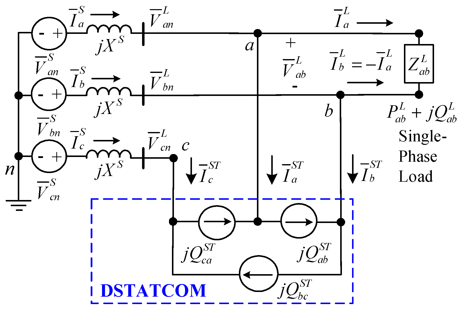
Figure 1 illustrates the study system for deriving the DSTATCOM compensation algorithm. A shunt type of DSTATCOM is installed for the on-site single-phase load compensation. The feedforward compensation algorithm detects the load power parameters,
and
, and sends three reactive power compensation commands,
, to the DSTATCOM’s main circuit arms. The three DSTATCOM arms independently regulate their reactive power inputs, then the synthesized DSTATCOM line current compensates the unbalanced single-phase load current. Consequently, the source currents are balanced with a unity power factor. Using the symmetrical components method, we derived the feedforward compensation algorithm.
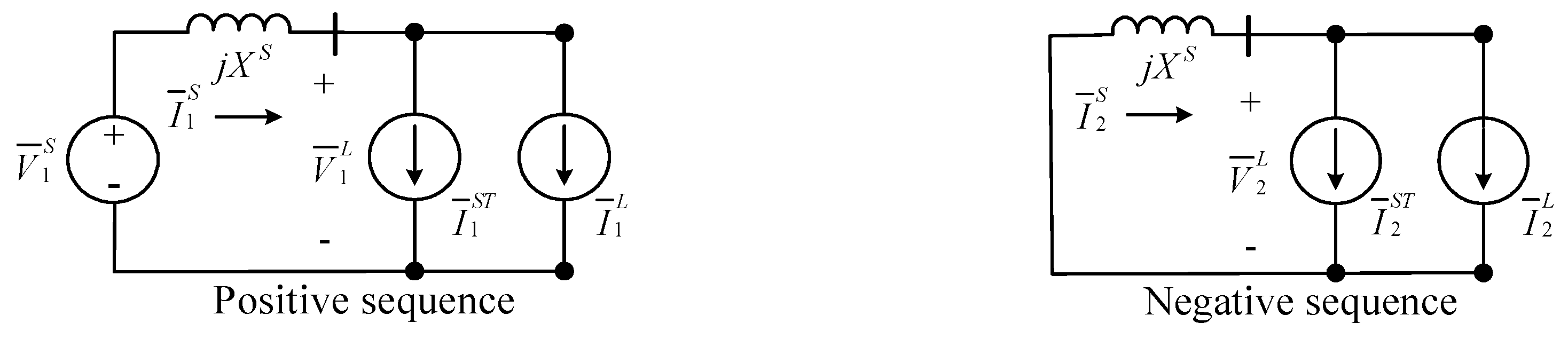
Figure 2 shows the phase-sequence circuits of
Figure 1.
Equation (1) expresses the line voltage of the load bus illustrated in
Figure 1, where
represents the line voltage. The phase-
a load current is shown in Equation (2), in which the relationship of
is used. The symmetrical components of the load current are then calculated using Equation (3).
Equation (3) can be rewritten as rectangular forms, as indicated in Equations (4) and (5). The zero-sequence component of the load current is zero. Equation (6) gives the three arm currents of the DSTATCOM, where the relationship of
is used. Equation (7) shows the DSTATCOM line currents. Using the symmetrical components transformation in Equation (8), Equation (9) shows the symmetrical components of the DSTATCOM line current in terms of the reactive power flows of the three DSTATCOM arms. For a DSTATCOM with a delta-connected main circuit, the zero-sequence current,
, in Equation (8) is zero.
As shown in
Figure 2, for the single-phase load compensation, the DSTATCOM should compensate the entire negative-sequence component and imaginary part of the positive-sequence component currents generated by the single-phase load, as revealed in Equation (10) [
21,
22]. The source current only supplies the real part of the positive-sequence load current. As a result, with the assistance of the DSTATCOM compensation, the source current is balanced with a unity power factor.
Finally, combining Equations (4), (5) and (9), (10), we obtained the required load compensation algorithm of each DSTATCOM arm for real-time single-phase load compensation, as indicated by Equation (11). Equation (11) is very compact and suitable for the SDBC-MMCC-based DSTATCOM. The sizing of the DSTATCOM can easily be calculated using Equation (11). The DSTATCOM is treated as a reactive power load in the compensation. The reactive power flow of each DSTATCOM arm, which can be inductive or capacitive, is independently controlled by the compensation algorithm in Equation (11). By using power calculation definitions,
and
, in the time domain, Equation (12) shows another version of Equation (11) for the DSATCOM, where
T is the period of the fundamental frequency. Equation (12) can easily be digitized and implemented in a digital controller. Finally, Equation (13) shows the three-phase source current with DSTATCOM compensation.
3. DSTATCOM Main Circuit
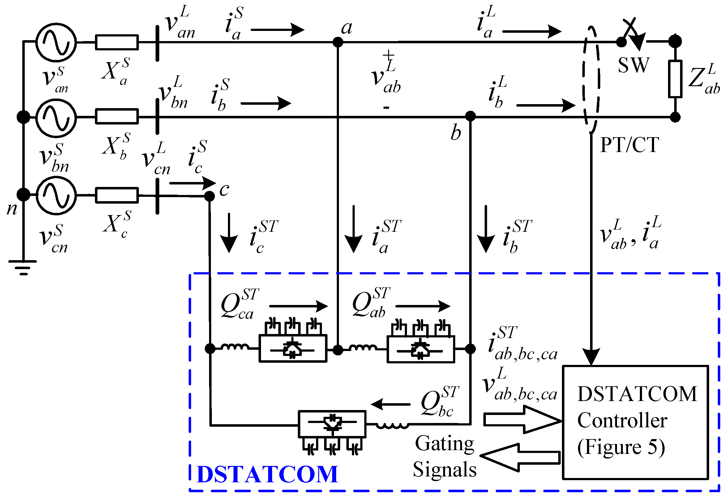
Figure 3 shows a three-phase power distribution system, a single-phase load, and the proposed seven-level, SDBC-MMCC-based DSTATCOM as the test system in the paper. Each STATCOM arm consists of an internal voltage source,
, modulated by a seven-level, cascade full-H-bridge converter and a commutation reactor,
. In this study, each DSTATCOM arm is equivalent to a purely reactive power load.
The reactive power flows of these three DSTATCOM arms are regulated independently for the single-phase load compensation. The power inputs of each DSTATCOM arm in
Figure 3 are expressed in Equations (14) and (15), respectively. An indirect phasor-domain power angle regulation method is used for the reactive power control in the DSTATCOM. For a reactive power demand, the DSTATCOM controller regulates the power angle,
, to absorb or release the active power from the power source according to Equation (14). The active power flow charges or discharges the DC-link capacitors and then regulates the DC-link voltages. Finally, the cascaded DC-link voltages synthesize the internal voltage,
, then the DSTATCOM absorbs capacitive or inductive reactive power according to Equation (15). When the reactive power response is completed, the power angle returns to near-zero values. With the delta-connected main circuit, the three DSTATCOM arms achieve phase-independent operation. Hence, much like a traditional SVC, the DSTATCOM can easily compensate the unbalanced load current and correct the power factor caused by a single-phase load.
A typical staircase modulation scheme, depicted in
Figure 4, enables the DSTATCOM main circuit to operate with high efficiency. Each level and internal voltage waveform of the DSTATCOM arm
a-b in
Figure 3 are also shown [
21]. The internal voltage
shows a staircase waveform. The three switching angles,
–
, should be determined to minimize the harmonics generated. The internal voltage
in
Figure 4 can be represented as a Fourier series, as detailed in Equation (16), where
is the harmonic order (
). Ideally, the harmonic order contains only odd-order components. Equation (17) shows the harmonic components in Equation (16).
In Equation (17), setting
produces the fundamental component
, which consists of the DC-link voltage
and three switching angles,
–
. The fundamental component
is used for the reactive power regulation. To eliminate the specified harmonic orders, a harmonic-minimizing method is used [
23]. Assigning
for the fundamental-component modulation and setting
for the 5th and 7th orders’ harmonic cancellation produces Equation (18). Subsequently, solving Equation (18) results in the required switching angles, namely,
=
,
=
,
=
.
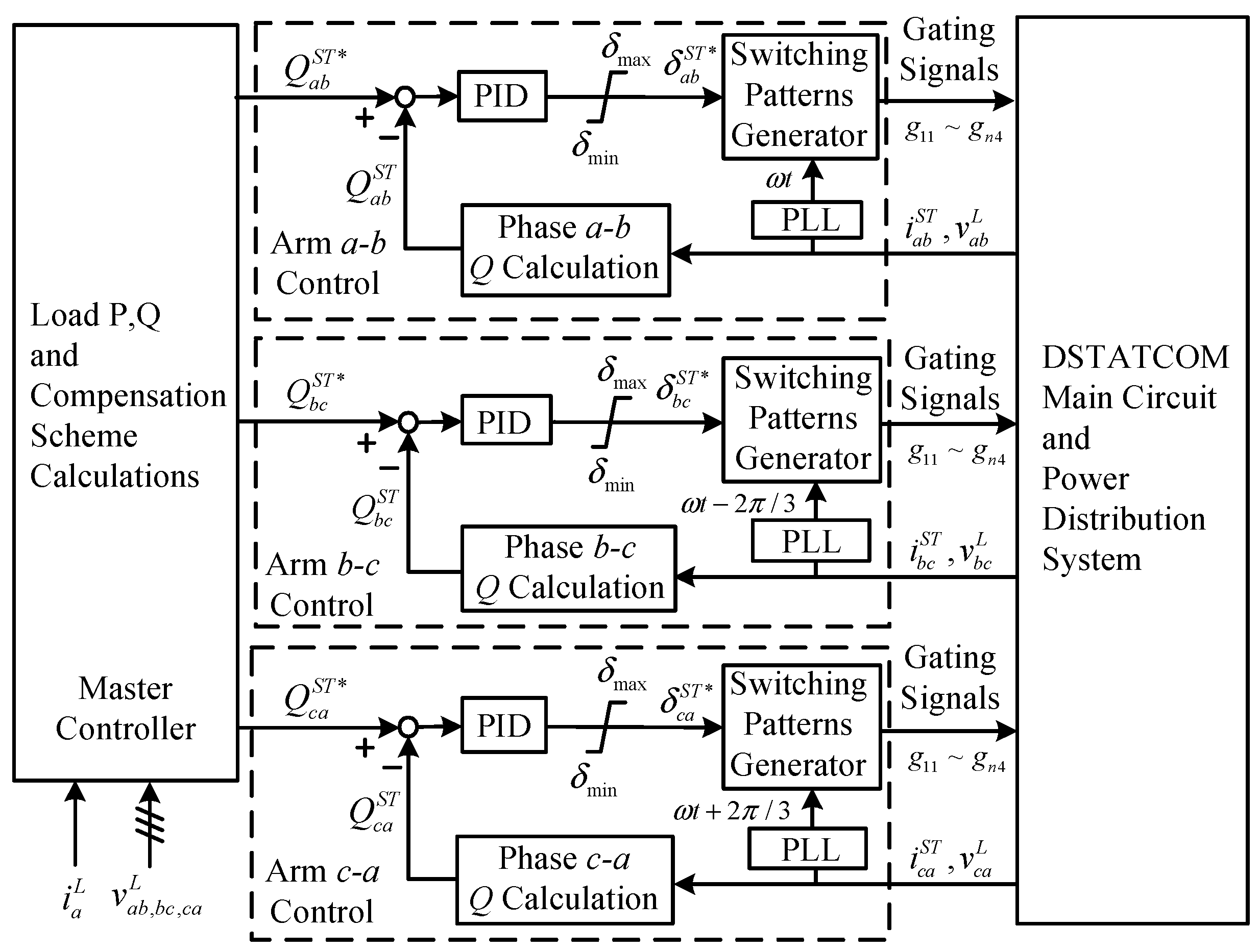
Figure 5 depicts the functional block diagram of the DSTATCOM controller proposed in this paper. As noted, the control algorithm using Equation (11) calculates the required reactive power values of the three DSTATCOM arms in real time. Three well-tuned proportional integral derivative (PID) feedback controllers in the inner loops regulate the reactive power inputs of the three DSTATCOM arms independently, as shown in Equation (19). The three output commands of the PID controllers,
, generate the gating signals, as shown in
Figure 4 for these switching elements in the three DSTATCOM arms. With the proposed controller shown in
Figure 5, the DSTATCOM completes the single-phase load compensation in real time. The DSTATCOM controller in
Figure 5 requires a fast power detection method.
Figure 6 schematizes the fast calculation method of active and reactive powers that applies the single-phase
reference axis method. Applying this fast calculation results in the load power values for Equation (11) and the reactive power inputs of the three DSTATCOM arms in real time.
4. Simulation Verification
Figure 7 shows the simulation system, which was developed in the MATLAB/SimuLink program for a preliminary verification of the proposed DSTATCOM. A single-phase inductive load was used in the testing. First, the DSTATCOM main circuit was built according to
Figure 3. In the simulation, the switch (SW) in
Figure 7 was closed at t = 0.605 s to make a step response caused by the single-phase load. With the setting, the transient and steady-state performances of the DSTATCOM compensation were observed from the simulation results.
Appendix A lists the system parameters.
Figure 8 and
Figure 9 are the simulation results.
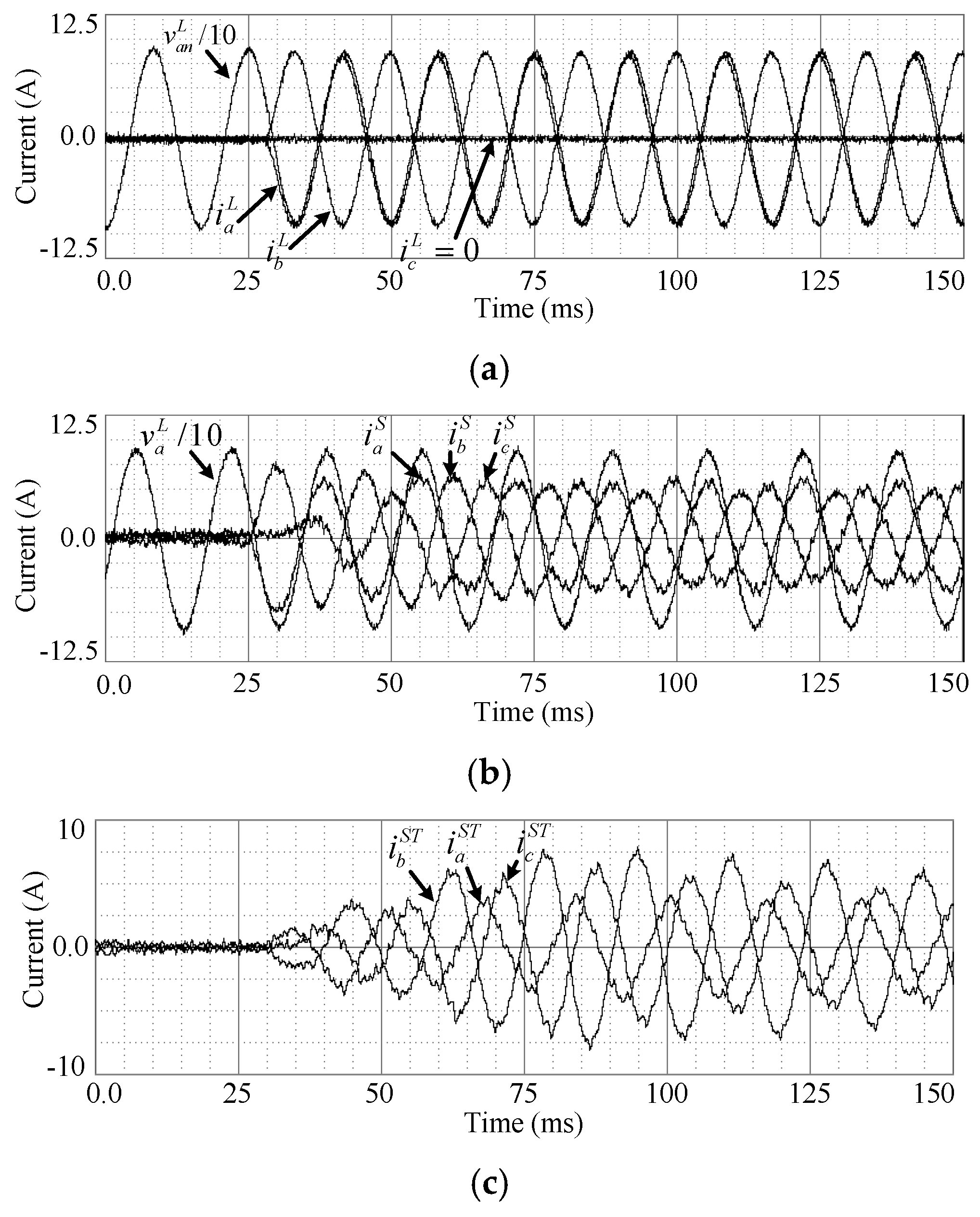
Figure 8a shows the transient load current response. With the assistance of the DSTATCOM, the three-phase source current was corrected to be balanced with a unity power factor, as shown in
Figure 8b.
Figure 8c depicts the synthesized line current of the DSTATCOM.
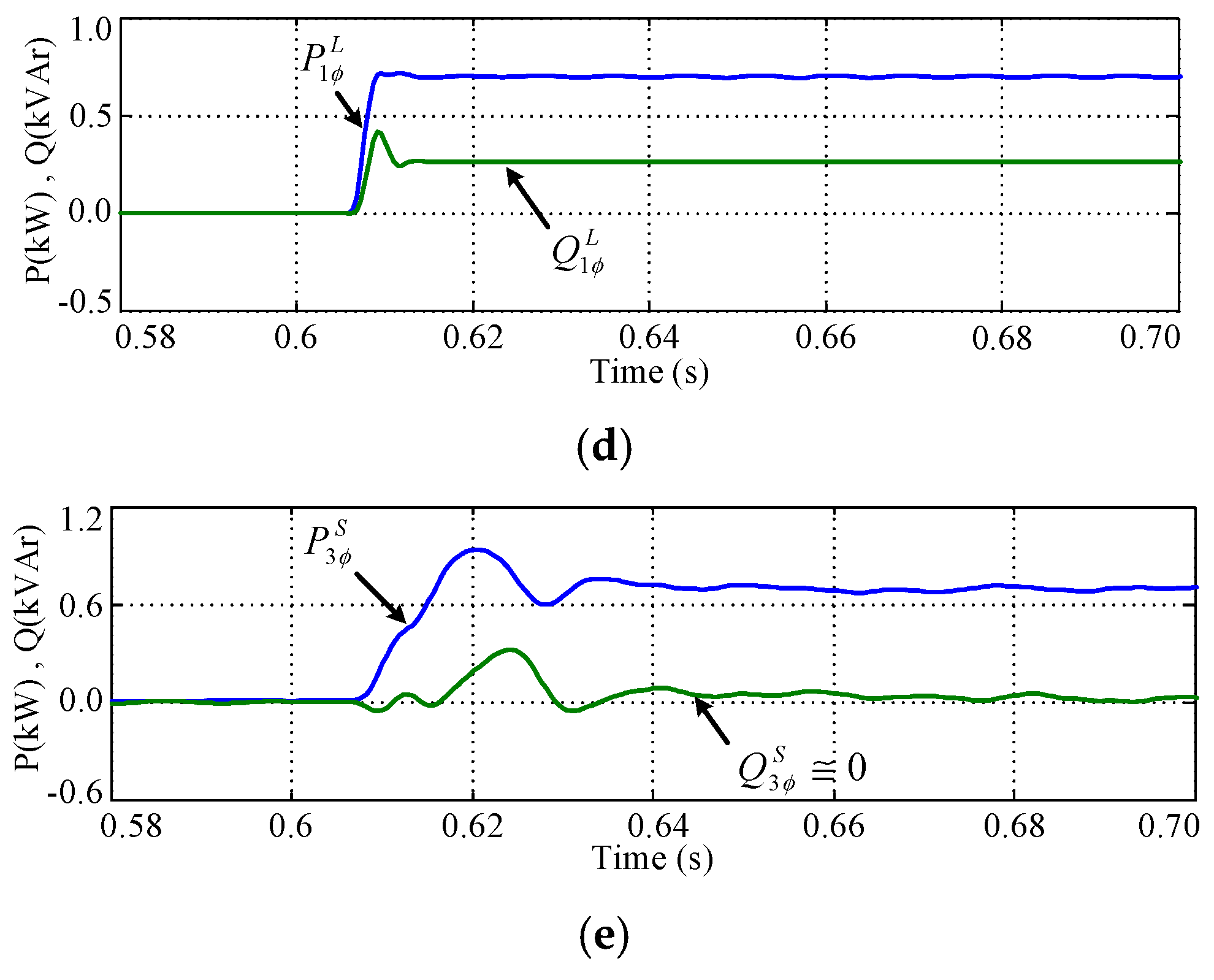
Figure 8d,e show the power flows from the power source to the load, which reveal that the DSTATCOM very rapidly compensated the reactive power demand of the load.
Figure 9 shows the compensation response in the DSTATCOM.
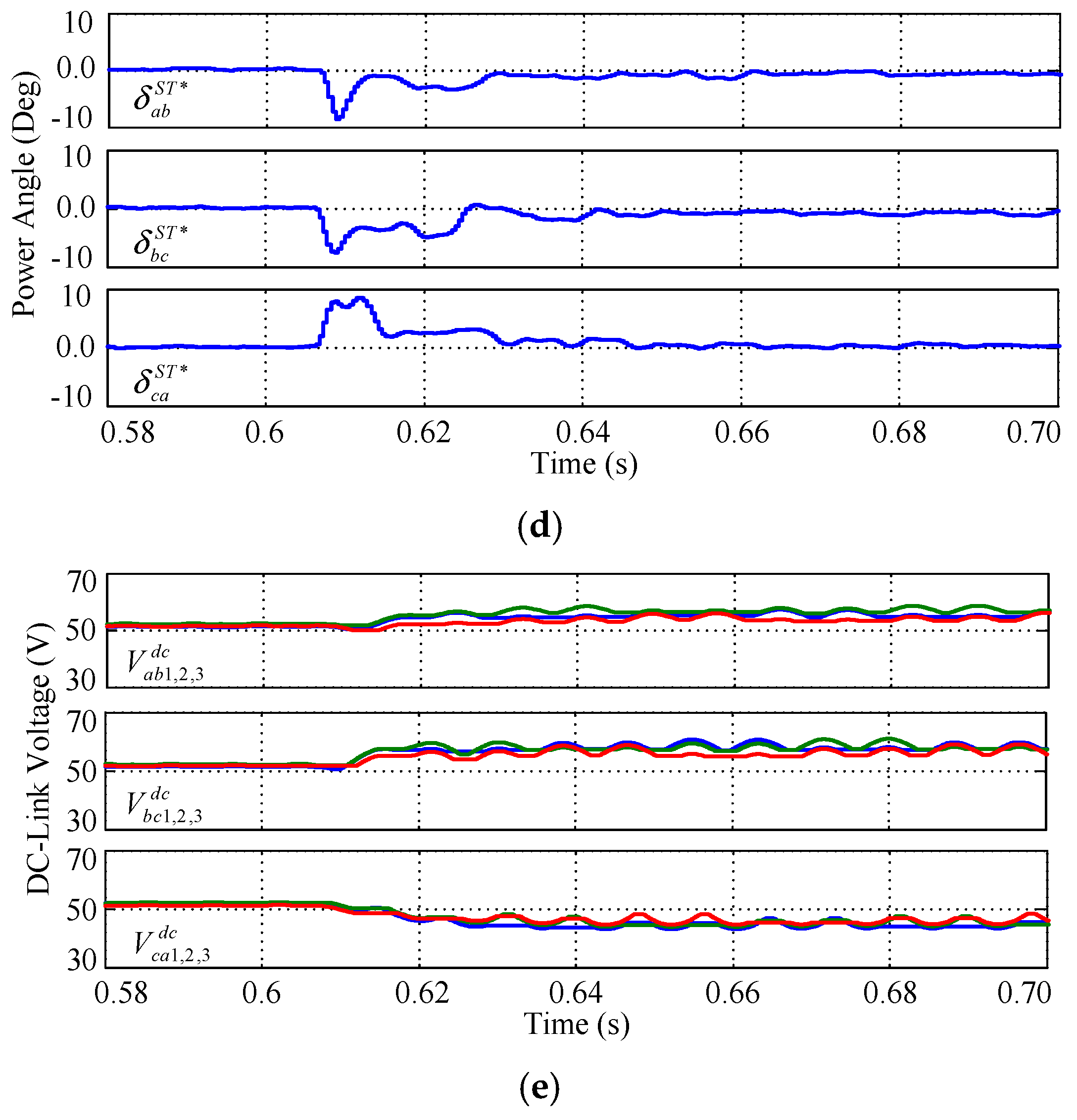
Figure 9a is a recording of the internal voltage responses in the three DSTATCOM arms. When the single-phase load was switched in, the three DSTATCOM arms changed to phase-independent operation, as shown in
Figure 9a,b.
Figure 9c–e reveal other DSTATCOM responses in the single-phase load compensation for reference.
The simulation results in
Figure 8 and
Figure 9 clearly indicate that the proposed DSTATCOM discussed in this paper is suitable for single-phase load compensation. It is also observed that the unbalanced operation of the three DSTATCOM arms produce high-order harmonic currents. The harmonic currents tend to flow into the system and aggravate the electric power quality. An adequate front-end filter can be installed to lessen the harmonic current pollution. Increasing the cascade numbers of the FHB cells in the DSTATCOM main circuit can markedly reduce the high-order harmonic currents.
Figure 10 shows the steady-state power flow with the DSTATCOM compensation. It can be observed that the DSTATCOM offers a path to rearrange the power flow for single-phase load compensation.
5. Hardware Experimental Results
Figure 11 shows the hardware prototype test system constructed in the laboratory, and
Appendix B lists the system parameters used. A single-phase load was used for verification testing in the physical experiment. The SDBC-MMCC-based DSTATCOM main circuit had a seven-level, transformerless configuration with a delta connection. In the hardware implementation of the DSTATCOM main circuit, insulated-gate bipolar transistors (IGBTs) were used. The DSTATCOM controller was a multi-TMS320F2812 DSP-based system with a sampling time of 0.52 ms to digitize the three PID controllers in
Figure 5. The control program in the multi-DSP-based controller was first developed in C language on a host PC. The execution file was downloaded to the multi-DSP-based controller through Joint Test Action Group (JTAG) data links. Two multi-channel digital scopes were employed to record the transient responses of the DSTATCOM. During the DSTATCOM operation, some selected on-line calculation results in the controller were sent to the host PC for further evaluation.
Figure 12 and
Figure 13 reveal the hardware experimental results.
Figure 12 shows the current responses with DSTATCOM compensation. In
Figure 12a, the switching-in of the single-phase load created an unbalanced operation. The single-phase load operation requires active power with a lagging power factor.
Figure 12b illustrates the source current response; the phase-
a-to-ground voltage waveform was recorded at the same time for reference. With the real-time compensation of the DSTATCOM, the source current was corrected very quickly to be balanced with a unity power factor.
Figure 12c shows the transient response of the synthesized DSTATCOM line current in the compensation.
Table 1 records the steady-state DSTATCOM compensation result in
Figure 12. The current unbalanced ratio
, expressed in Equation (20) indicates the effect of current balancing in the power source. The unbalanced ratio of the load current,
, was 100%. With DSTATCOM compensation, the unbalanced ratio of the source current,
, was substantially improved to a nearly perfect value of 3.26%.
Figure 13 shows other responses in the DSTATCOM main circuit. The three DSTATCOM arms changed to phase-independent operation when the single-phase load was switched in. The physical test results agreed with the simulation results presented in
Figure 9. The transient compensation response of the DSTATCOM was quite fast. The delta-connected DSTATCOM main circuit and the harmonics-minimizing method eliminated the specified harmonic components in the synthesized DSTATCOM line currents, as shown in
Figure 13b,c. However, high-order harmonic currents were unavoidably generated in the three DSTATCOM arms.
The hardware experimental results verified that the proposed SDBC-MMCC-based DSTATCOM is suitable for real-time phase balancing and power factor correction of single-phase loads in three-phase, three-wire power distribution systems.


