Integration of Stationary Batteries for Fast Charge EV Charging Stations


Abstract
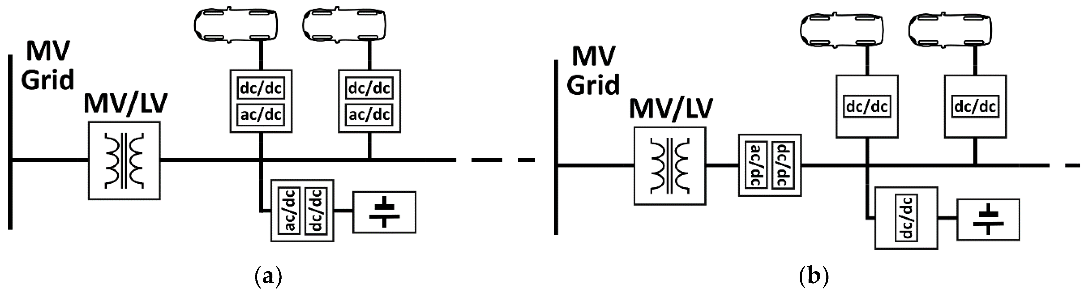
1. Introduction
2. Materials and Methods
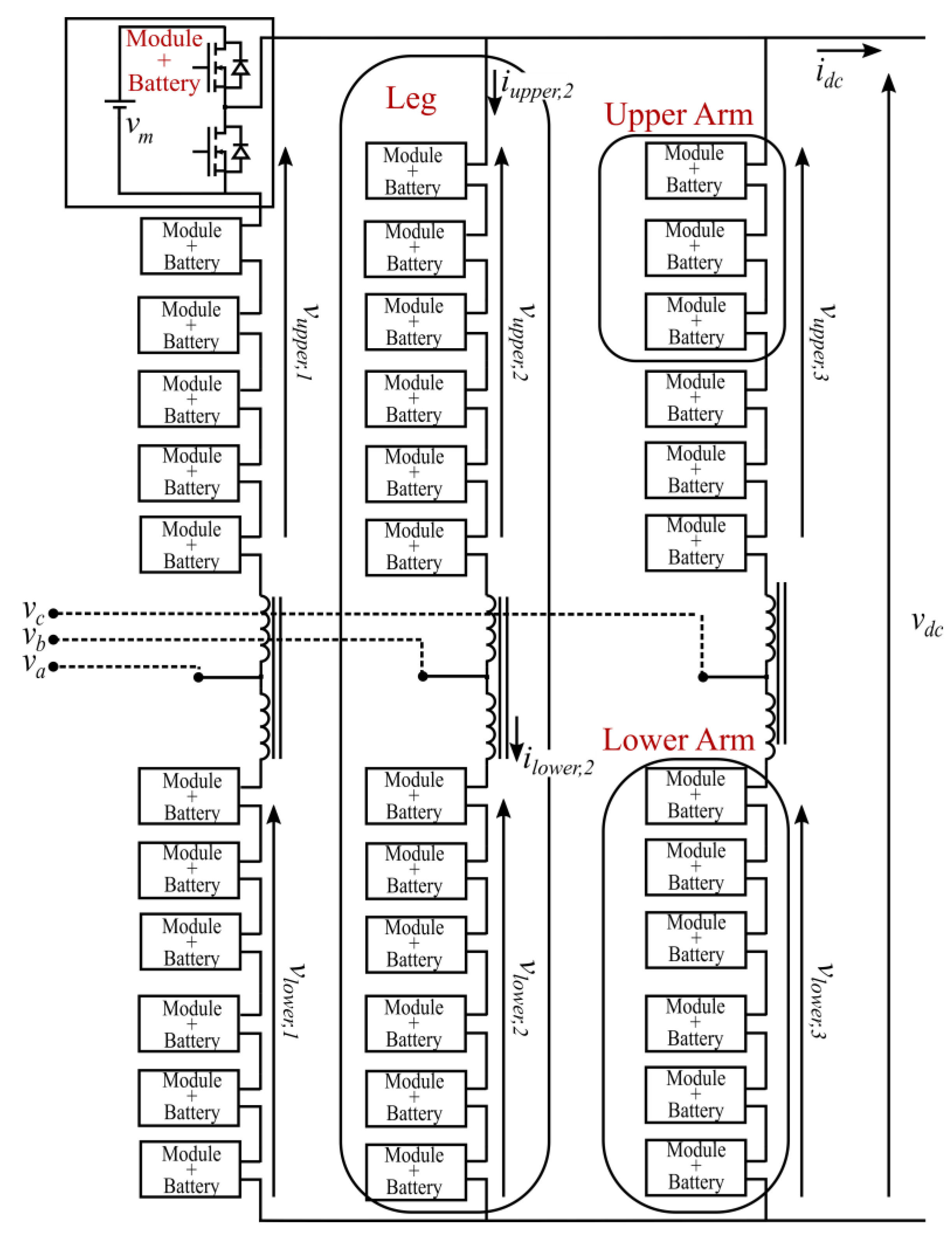
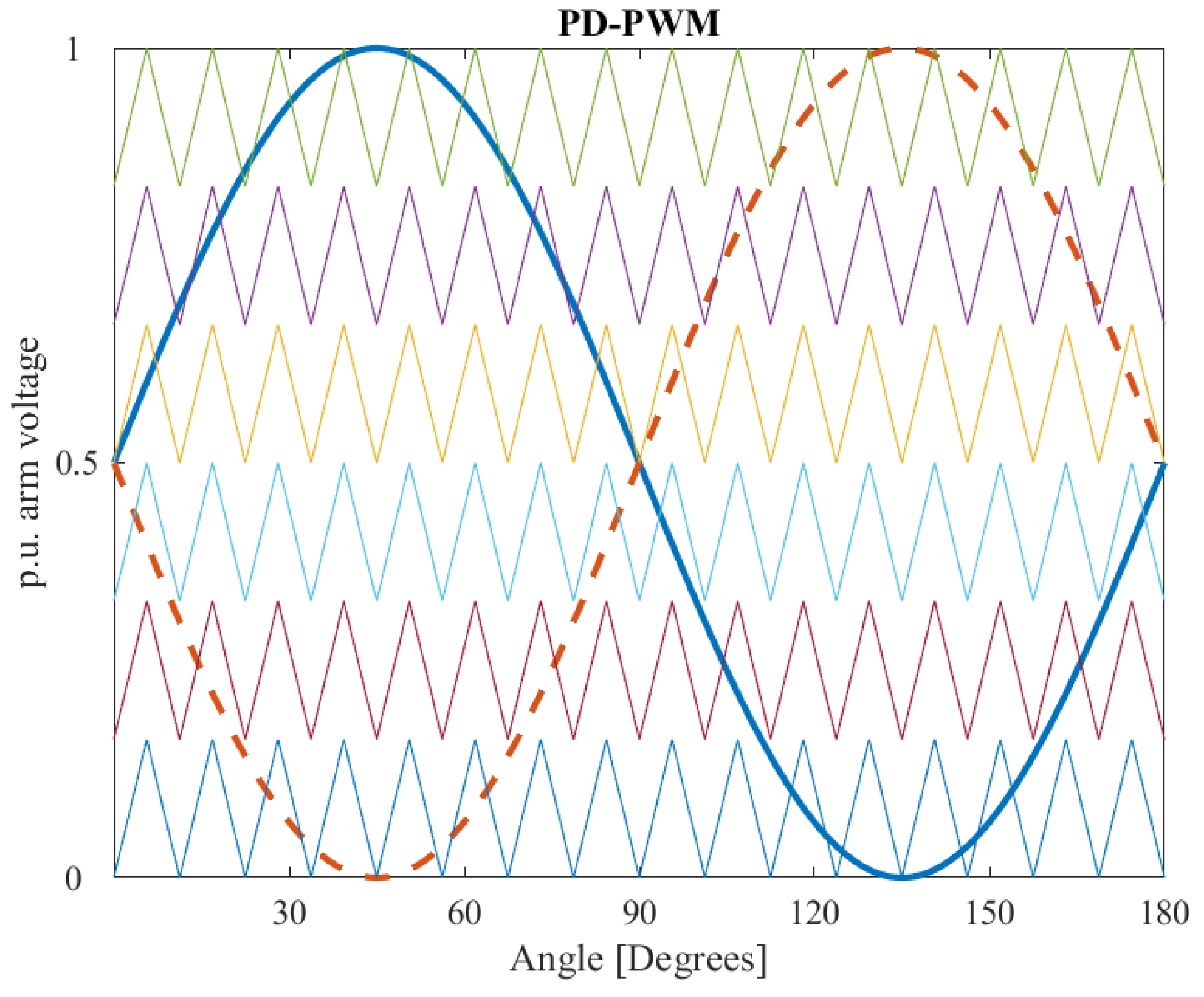
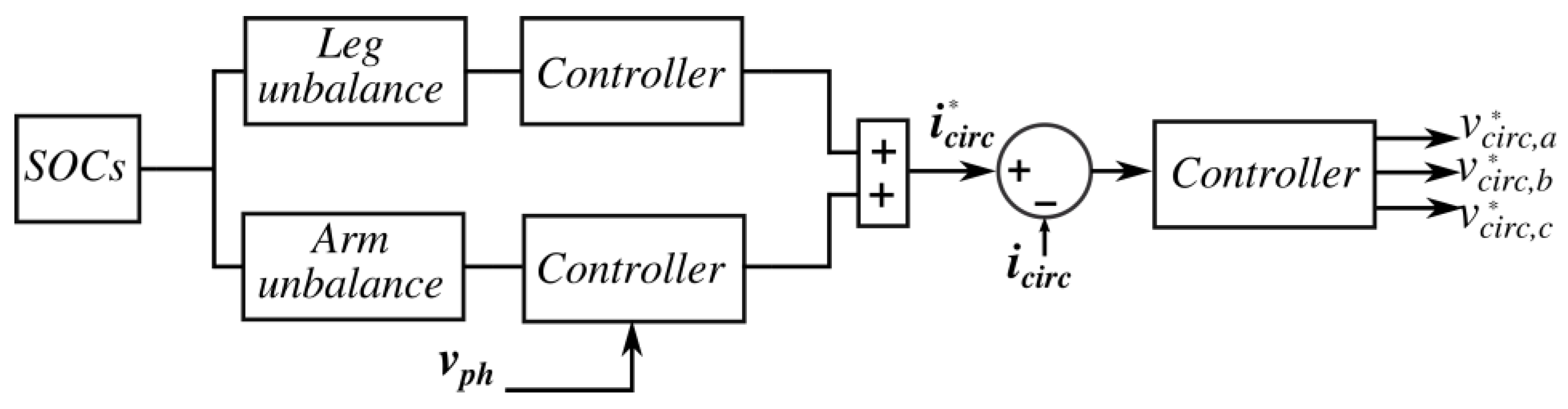
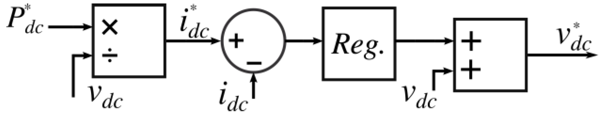
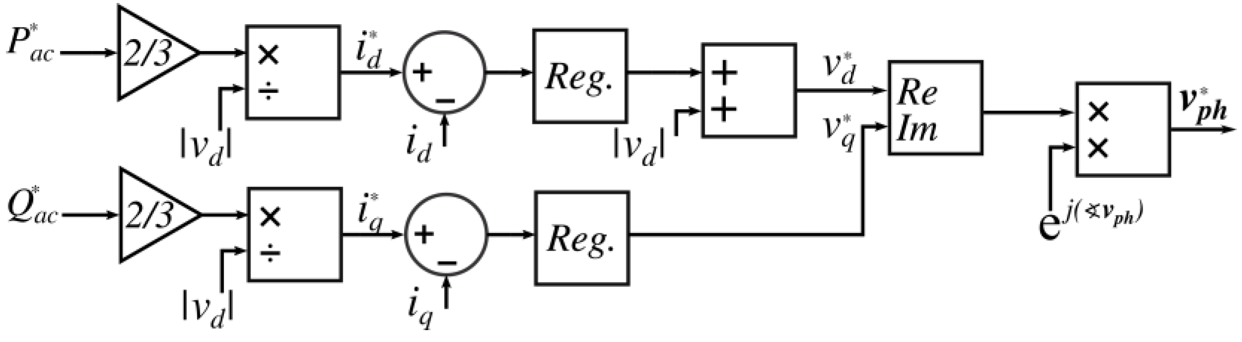
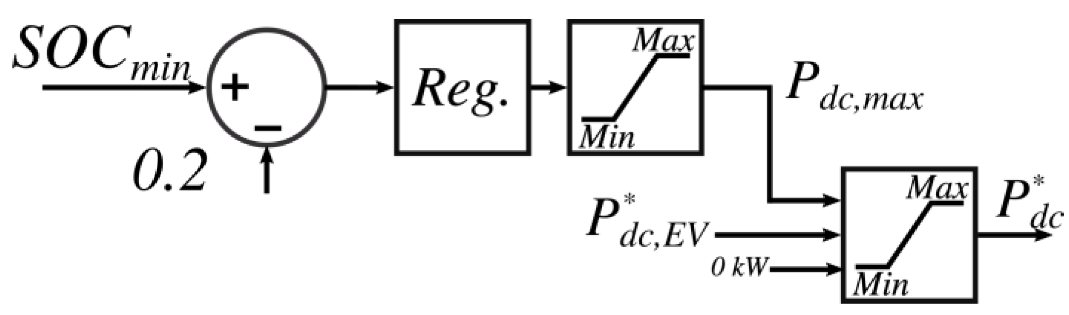
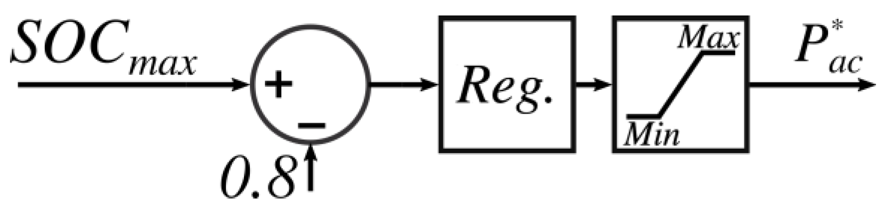
2.1. Converter Control
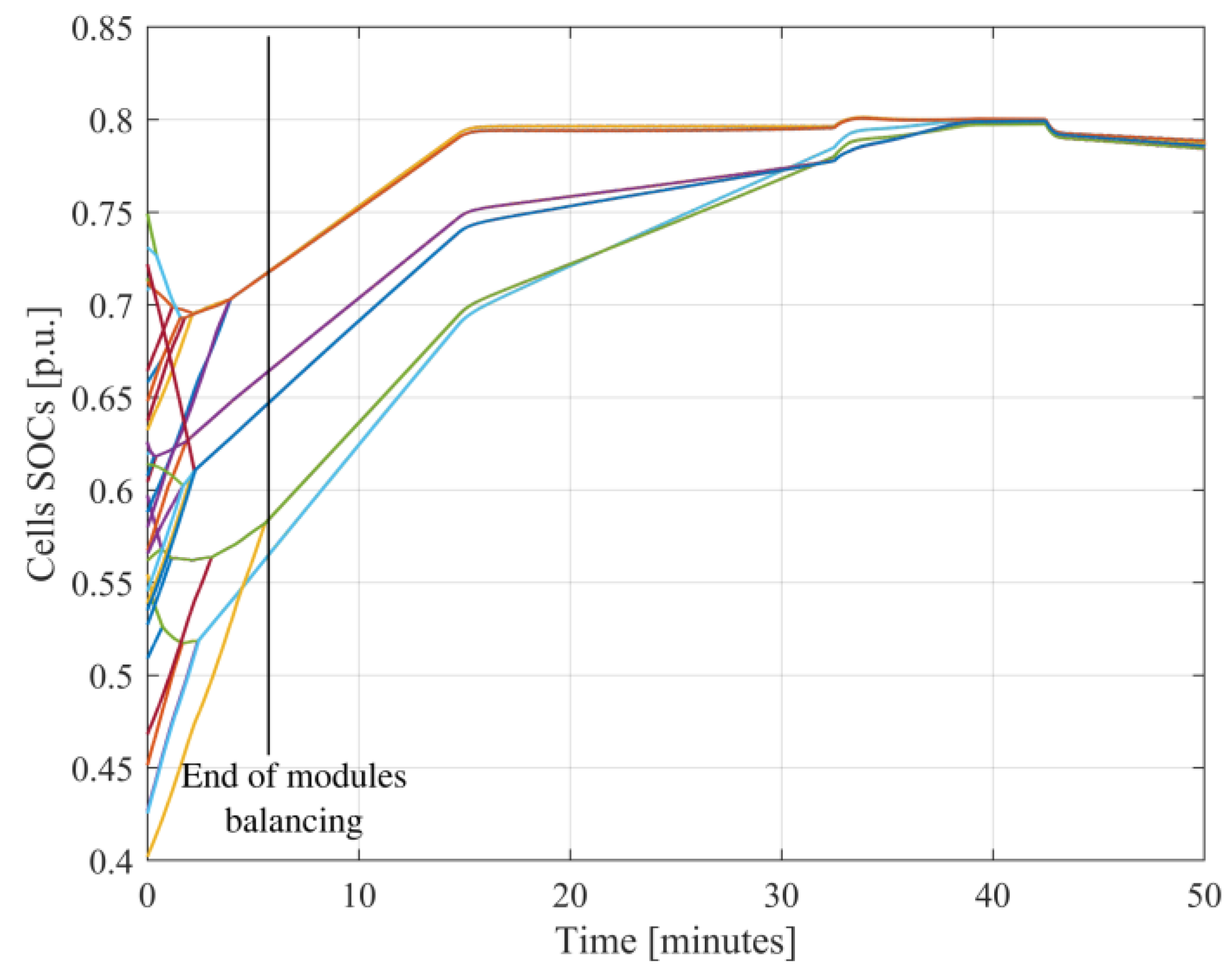
- Balancing among battery modules belonging to same arm is achieved by sorting the cells on the basis of their SOC and using the most charged (discharged) when the current is discharging (charging) them;
- Balancing among battery modules belonging to different legs is achieved by changing the dc reference voltage of each leg allowing the circulation of a dc current among the legs (this current does not interest the load);
- Balancing among upper and lower arms is achieved using an oscillating zero-sequence current (equal on each phase) that takes more energy from the lower (upper) arm if this is the more charged.
2.2. Converter Sizing
2.3. Test Setup
3. Results
4. Discussion
Author Contributions
Funding
Conflicts of Interest
References
- Hoimoja, H.; Rufer, A.; Dziechciaruk, G.; Vezzini, A. An ultrafast EV charging station demonstrator. In Proceedings of the International Symposium on Power Electronics Power Electronics, Electrical Drives, Automation and Motion, Sorrento, Italy, 20–22 June 2012; pp. 1390–1395. [Google Scholar]
- Overview of Battery Cell Technologies, Marcel MEEUS. Energy Materials Industrial Research Initiative (EMIRI). Available online: https://europa.eu/sinapse/webservices/dsp_export_attachement.cfm?CMTY_ID=0C46BEEC-C689-9F80-54C7DD45358D29FB&OBJECT_ID=230DABFD-90AB-8F7D-083EF5BD909DD025&DOC_ID=9C5B91FE-01BC-5F72-79D01E1939A9EE53&type=CMTY_CAL (accessed on 8 October 2019).
- Richard, L.; Petit, M. Fast charging station with battery storage system for EV: Grid services and battery degradation. In Proceedings of the 2018 IEEE International Energy Conference (ENERGYCON), Limassol, Cyprus, 3–7 June 2018; pp. 1–6. [Google Scholar]
- Voelcker, J. Porsche’s fast-charge power play: The new, all-electric Taycan will come with a mighty thirst. This charging technology will slake it. IEEE Spectr. 2019, 56, 30–37. [Google Scholar] [CrossRef]
- Jochem, P.; Landes, P.; Reuter-Oppermann, M.; Fichtner, W. Workload Patterns of Fast Charging Stations Along the German Autobahn. World Electr. Veh. J. 2016, 8, 936–942. [Google Scholar] [CrossRef]
- Srdic, S.; Lukic, S. Toward Extreme Fast Charging: Challenges and Opportunities in Directly Connecting to Medium-Voltage Line. IEEE Electrif. Mag. 2019, 7, 22–31. [Google Scholar] [CrossRef]
- Martinez-Rodrigo, F.; Ramirez, D.; Rey-Boue A., B.; de Pablo, S.; Herrero-de Lucas L., C. Modular Multilevel Converters: Control and Applications. Energies 2017, 10, 1709. [Google Scholar] [CrossRef]
- Van Hertem, D.; Gomis-Bellmunt, O.; Liang, J. HVDC Grids: For Offshore and Supergrid of the Future; John Wiley & Sons: New York, NY, USA, 2016. [Google Scholar]
- Li, J.; Bhattacharya, S.; Huang, A.Q. A New Nine-Level Active NPC (ANPC) Converter for Grid Connection of Large Wind Turbines for Distributed Generation. IEEE Trans. Power Electron. 2011, 26, 961–972. [Google Scholar] [CrossRef]
- Ruderman, A.; Reznikov, B. Time domain evaluation of filterless grid-connected multilevel PWM converter voltage quality. In Proceedings of the 2010 IEEE International Symposium on Industrial Electronics, Bari, Italy, 4–7 July 2010; pp. 2940–2945. [Google Scholar]
- D’Arco, S.; Piegari, L.; Tricoli, P. A modular converter with embedded battery cell balancing for electric vehicles. In Proceedings of the 2012 Electrical Systems for Aircraft, Railway and Ship Propulsion, Bologna, Italy, 16–18 October 2012; pp. 1–6. [Google Scholar]
- D’Arco, S.; Quraan, M.; Tricoli, P.; Piegari, L. Battery charging for electric vehicles with modular multilevel traction drives. In Proceedings of the 7th IET International Conference on Power Electronics, Machines and Drives (PEMD 2014), Manchester, UK, 8–10 April 2014; p. 2. [Google Scholar]
- Quraan, M.; Yeo, T.; Tricoli, P. Design and Control of Modular Multilevel Converters for Battery Electric Vehicles. IEEE Trans. Power Electron. 2015, 31, 507–517. [Google Scholar] [CrossRef]
- De Simone, D.; Piegari, L.; D’Areo, S. Comparative Analysis of Modulation Techniques for Modular Multilevel Converters in Traction Drives. In Proceedings of the 2018 International Symposium on Power Electronics, Electrical Drives, Automation and Motion (SPEEDAM), Amalfi, Italy, 20–22 June 2018; pp. 593–600. [Google Scholar]
- Ouerdani, I.; Bennani, A.; Ben, A.; Slama, B.; Montesinos Miracle, D. Phase Opposition Disposition PWM Strategy and Capacitor Voltage Control for Modular Multilevel Converters. In Proceedings of the International Conference on Recent Advances in Electrical Systems, Hammamet, Tunisia, 20–22 December 2016. [Google Scholar]
- Brando, G.; Dannier, A.; Spina, I.; Tricoli, P. Integrated BMS-MMC Balancing Technique Highlighted by a Novel Space-Vector Based Approach for BEVs Application. Energies 2017, 10, 1628. [Google Scholar] [CrossRef]
- Zahoor, W.; Zaidi, S.H. Synchronization and dq current control of grid-connected voltage source inverter. In Proceedings of the 17th IEEE International Multi Topic Conference 2014, Karachi, Pakistan, 8–10 December 2014; pp. 462–466. [Google Scholar]
- Piegari, L.; Tricoli, P. A control algorithm of power converters in smart-grids for providing uninterruptible ancillary services. In Proceedings of the 14th International Conference on Harmonics and Quality of Power - ICHQP 2010, Bergamo, Italy, 26–29 September 2010; pp. 1–7. [Google Scholar]
- Electric Vehicle Database. Available online: https://ev-database.org/car/1145/BMW-i3-120-Ah (accessed on 30 September 2019).
- Electric Vehicle Database. Available online: https://ev-database.org/car/1144/Nissan-Leaf-eplus (accessed on 30 September 2019).
- Electric Vehicle Database. Available online: https://ev-database.org/car/1116/Porsche-Taycan-Turbo-S (accessed on 30 September 2019).


| System | kW | Availability |
|---|---|---|
| Combined Charging System (CCS) | 50–350 | United States European Union Australia, Korea |
| China GB/T | 237.5 | China, India |
| Tesla Supercharger | 135 | Global |
| CHAdeMO | 50–100 | Global |
| Vehicle | Usable Battery Capacity (kWh) | Charging Power (kW) | |
|---|---|---|---|
| EV1 | BMW i3 | 37.9 | 46 |
| EV2 | Nissan Leaf e+ | 56 | 100 |
| EV3 | Porsche Taycan | 83.7 | 350 |
| Converter Parameters | ||
|---|---|---|
| Parameter | Value | Meas. Unit |
| vph,rated | 311 | V |
| vcell,min | 3 | V |
| vdc,min | 828 | V |
| 6 | ||
| 46 | ||
| vmodule,min | 138 | V |
| Estorage | 69 | kWh |
© 2019 by the authors. Licensee MDPI, Basel, Switzerland. This article is an open access article distributed under the terms and conditions of the Creative Commons Attribution (CC BY) license (http://creativecommons.org/licenses/by/4.0/).
Share and Cite
De Simone, D.; Piegari, L. Integration of Stationary Batteries for Fast Charge EV Charging Stations. Energies 2019, 12, 4638. https://doi.org/10.3390/en12244638
De Simone D, Piegari L. Integration of Stationary Batteries for Fast Charge EV Charging Stations. Energies. 2019; 12(24):4638. https://doi.org/10.3390/en12244638
Chicago/Turabian StyleDe Simone, Davide, and Luigi Piegari. 2019. "Integration of Stationary Batteries for Fast Charge EV Charging Stations" Energies 12, no. 24: 4638. https://doi.org/10.3390/en12244638
APA StyleDe Simone, D., & Piegari, L. (2019). Integration of Stationary Batteries for Fast Charge EV Charging Stations. Energies, 12(24), 4638. https://doi.org/10.3390/en12244638