Article

Experimental Investigation of Productivity, Specific Energy Consumption, and Hole Quality in Single-Pulse, Percussion, and Trepanning Drilling of IN 718 Superalloy

1
Manufacturing Department, School of Aerospace, Transport and Manufacturing, Cranfield University, Cranfield, Bedfordshire MK43 0AL, UK
2
School of Engineering and Digital Sciences, Nazarbayev University, Nur-Sultan 010000, Kazakhstan
*
Author to whom correspondence should be addressed.
Energies 2019, 12(24), 4610; https://doi.org/10.3390/en12244610
Submission received: 7 October 2019 / Revised: 28 November 2019 / Accepted: 3 December 2019 / Published: 4 December 2019
(This article belongs to the Special Issue Energy Efficiency of Manufacturing Processes and Systems)

Abstract

:
Laser drilling is a high-speed process that is used to produce high aspect ratio holes of various sizes for critical applications, such as cooling holes in aero-engine and gas turbine components. Hole quality is always a major concern during the laser drilling process. Apart from hole quality, cost and productivity are also the key considerations for high-value manufacturing industries. Taking into account the significance of improving material removal quantity, energy efficiency, and product quality, this study is performed in the form of an experimental investigation and multi-objective optimisation for three different laser drilling processes (single-pulse, percussion, and trepanning). A Quasi-CW fibre laser was used to produce holes in a 1 mm thick IN 718 superalloy. The impacts of significant process parameters on the material removal rate (MRR), specific energy consumption (SEC), and hole taper have been discussed based on the results collected through an experimental matrix that was designed using the Taguchi method. The novelty of this work focuses on evaluating and comparing the performance of laser drilling methods in relation to MRR, SEC, and hole quality altogether. Comparative analysis revealed single-pulse drilling as the best option for MRR and SEC as the MRR value reduces with percussion and trepanning by 99.70% and 99.87% respectively; similarly, percussion resulted in 14.20% higher SEC value while trepanning yielded a six-folds increase in SEC as compared to single-pulse drilling. Trepanning, on the other hand, outperformed the rest of the drilling processes with 71.96% better hole quality. Moreover, optimum values of parameters simultaneously minimising SEC and hole taper and maximising MRR are determined using multi-objective optimisation.

Graphical Abstract

1. Introduction

Machining is a fundamental method to transform raw material into a finished product. Machining processes of various types are involved in crafting the solid structure into intricate parts of desired geometry. Despite the usage of advanced conventional machining technologies, manufacturing of complex parts with high accuracy has remained a challenge for the manufacturing industry. For instance, certain complex parts, such as gas turbine or aero-engine components need highly accurate and miniature-sized machining, which can be of microsize, such as holes in nozzle guide vane, turbine blade, fuel injector, and combustion chamber, are mainly in milli to microsize; therefore, the accomplishment of these complex holes warrants the selection of a highly accurate drilling process.
Inconel 718 is extensively used in the aerospace industry, particularly for manufacturing of aero-engine components that operate under high-temperatures. Conventional machining is difficult for this material because of its high strength and work hardening properties [1]. The machinability of superalloys can be improved using different machining methods, such as ultrasonic machining, electrochemical machining, water jet machining, and laser-assisted machining [2,3,4]. Laser drilling is a high power, high speed, and non-contact machining process, which is specified for the drilling of holes of various shapes and sizes in almost any material, such as composites, metals and non-metals [5]. During recent years, the laser drilling method has been proven as an important industrial process for producing cooling holes for aero-engine components where the size of hole ranges between 0.25 and 1.0 mm [
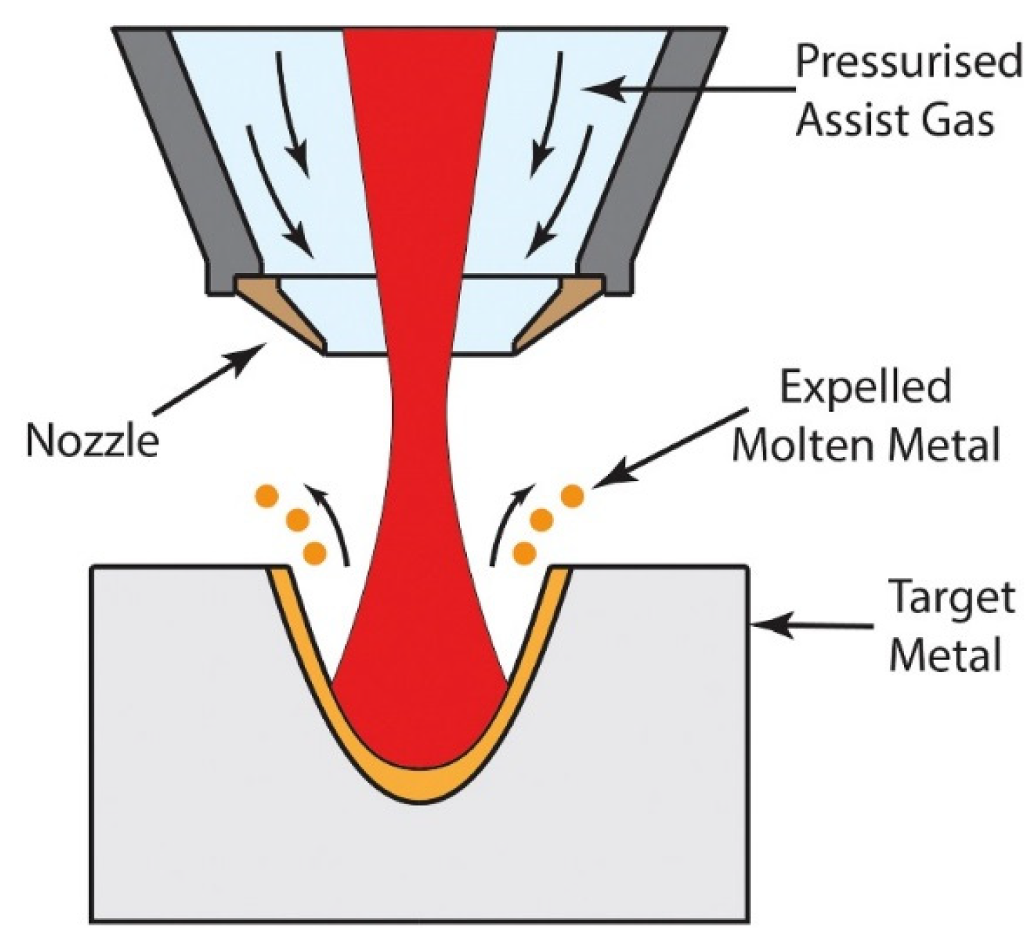
6]. During this method, a laser beam is focused on the workpiece surface, where the thermal energy transforms the substrate material into a molten metal that can be removed easily using the pressurised assist gas, as shown in Figure 1. In addition to that, the laser beam can heat the material instantly to its vaporisation temperature, and the vaporised material exits out of the hole. At this stage, vapour pressure may also be produced, which contributes to the expulsion of molten metal out of the hole cavity [7]; at the same time, the holes produced by the laser reveal some defects, such as recast layer, heat affected zone (HAZ), and hole taper, which may limit the utilisation of the laser drilling process in the industry. From the manufacturing perspective, product quality is always important. In the laser drilling process, the drilled hole quality is assessed by examining its geometrical and metallurgical features, such as circularity, hole taper, microcracks, HAZ, and recast layer thickness [
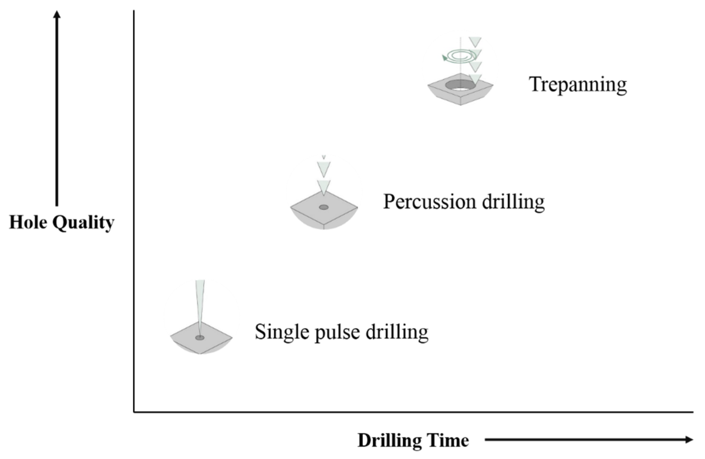
8]. Different drilling methods can be used to produce a particular hole geometry. Depending upon the application requirements, a distinctive method will be selected, as shown in Figure 2.
Methods that are commonly used for laser drilling include single-shot laser drilling, percussion, and trepan laser drilling. Single-shot laser drilling, also known as single-pulse drilling, is the most basic method in which a single high-energy pulse from the laser produces a hole throughout the material thickness. High productivity can be achieved with this simple drilling method. Single-shot drilling is preferable when production throughput has priority over quality. The percussion laser drilling method is quite similar to single-shot drilling and is directed by delivering consecutive laser pulses to a particular spot of the material. Using percussion drilling, high-quality holes are achieved as compared to single-pulse drilling. The fact is that less energy is applied to the material every time the pulse is fired; hence, avoiding the thermal defects, such as HAZ. Higher dimensional accuracy can be achieved with percussion drilling; however, this process is slower in contrast with single-pulse drilling. Trepan laser drilling or trepanning is used when the required shape has a size of large diameter. In this process, the hole is initially pierced into the substrate in the same way as percussion drilling followed by spiral configuration to cut a circular disc or cylindrical core from the material by rotating the laser beam around the circumference of the hole. The cylindrical core falls out after the required hole size is created. The drilling time is relatively longer as compared to other methods [10]. The relationship between drilling time and hole quality for different laser drilling processes is presented in Figure 3.
The laser drilling process is complex, and there are several parameters that affect the quality of manufactured holes. For improved drilling performance, researchers have been experimenting with various approaches, including different laser drilling methods and with process parameters of various levels. Panda et al. [11] investigated the influence of laser drilling process parameters on hole quality during percussion drilling of high carbon steel and found laser pulse width/duration as a critical parameter that increases the heat affected zone at higher values. Yilbas [12] employed a parametric study to observe the effects of different laser machining parameters on the drilled hole quality. This study revealed that pulse energy, pulse duration, pulse frequency, and laser focus position control the hole quality. In another study, Yilbas and Aleem [13] found that pulse energy, assist gas pressure, and focal position are the important parameters that influence the overall quality of the laser drilled hole. Ng and Li [7] found that high peak power and short pulse width combination improve the repeatability of holes. The Taguchi method was used by Chien and Hou [14] to analyse the impacts of different laser drilling process parameters on hole quality during trepanning. It was observed that improved hole quality could be obtained when higher pulse energy and lower trepan speed is used. An experimental investigation was performed by Morar et al. [15] to investigate the hole quality during laser trepanning of nickel-based superalloy; pulse width, pulse energy, and trepan speed were observed as the most influencing parameters affecting the quality of the drilled hole. Rajesh et al. [16] examined the effects of several laser drilling parameters on drilled hole quality and reported that pulse duration significantly influences the hole taper. Dhaker and Pandey [17] investigated the parameters influencing hole quality during laser trepanning. They concluded that the hole quality could be significantly improved by the proper control of laser drilling parameters.
Furthermore, productivity is an important attribute of the laser drilling process that is defined by the material removal rate (MRR). In the laser drilling process, MRR is influenced by the applied laser drilling parameters, i.e., pulse width, pulse frequency, pulse energy, and assist gas [11,18,19,20,21]. Higher productivity is always desirable for manufacturing industries as it reduces the cost of manufacturing of a component [2,22].
Energy consumption, needed for the manufacturing of products, is also the major concern of the manufacturing community because of the constant increase in energy cost and due to ecological effect linked with the production of energy and its use [23]. Reducing energy consumption is one of the top priorities of both national and international policies. The hefty CO2 emissions are the result of extensive use of energy in various manufacturing processes and are responsible for climatic changes. It is found that a large proportion (20–40%) of energy is wasted when performing industrial operations [24]. The International Energy Agency (IEA) underlined the necessity of energy efficiency evaluation in the direction of two-thirds energy intensity reduction of the world economy before 2050 [25]. Consequently, there is a need to evaluate the energy consumed during the manufacturing processes.
The energy efficiency of a laser-based process is low, but on the other hand, the material can be removed more precisely. Dahmen et al. [26] revealed that lasers could impart to sustainable manufacturing because of the minimal use of consumables, confined heat input even at low energy, saving of cost and energy for heat treatment, and with the aid of hybrid methods. Utilising more economical laser sources, for instance, disc or fibre lasers can also be examined as a possible energy efficient method. Similar findings were reported by Kaierle et al. [27]. An investigation was performed by Apostolos et al. [28] and Franco et al. [29] to evaluate laser drilling process energy efficiency by examining different process parameters using CO2 and femtosecond-pulsed fibre laser respectively. The results revealed that optimising the process parameters could lead to reducing the energy consumption of the process. Reduction in energy consumption will provide a great advantage to the industries by alleviating the cost of energy and at the same time reducing the energy crisis and air pollution problems.
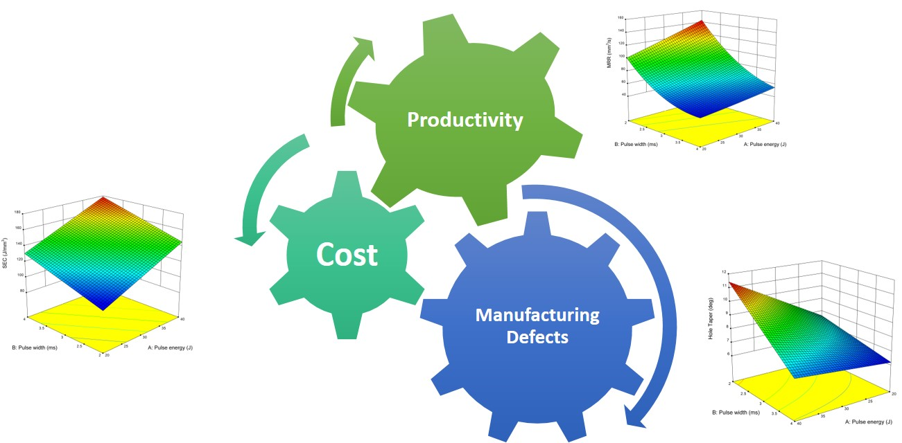
Manufacturing industries are continuously striving to enhance their competitive position through improved productivity and quality at a minimum possible cost that shows the importance of these factors for the industrial sector. From the literature, it has been found that little or no research is reported that characterise the laser drilling methods in terms of MRR, SEC, and hole quality altogether. Therefore, the objective of the presented study is to deliver a clear understanding of the impacts of different laser drilling methods and process parameters on productivity (material removal rate), cost (specific energy consumption), and hole quality (hole taper) in laser drilling of IN 718 superalloy. Three different laser drilling processes have been investigated, i.e., single-pulse, percussion, and trepanning. Further analysis has been performed using multi-objective optimisation to achieve the optimum levels of process parameters for maximum MRR, with minimum SEC and hole taper.

2. Materials and Methods

2.1. Experimental Setup

Laser drilling of nickel superalloy was performed at 90° to the material surface using three different methods, i.e., single-pulse, percussion, and trepanning. Inconel® alloy 718 (Goodfellow, UK) was used as a base material in this study. The size of the specimen was 100 × 100 × 1 mm (Figure 4a). Energy dispersive X-ray (EDX) analysis was performed to verify the chemical composition of the material and is provided in Table 1.
A Quasi-CW fibre laser (Model YLS-2000/20000-QCW) from IPG Photonics, UK, was used for this study. The laser drilling setup prepared for the experiments is presented in Figure 4b. The specification of laser system includes wavelength: 1070 nm, maximum average power: 2000 W, peak power: 20,000 W, maximum pulse energy: 200 J, pulse duration: 0.2–10 ms, and maximum pulse frequency: 2 kHz. The hole pitch was set at 5 mm to prevent the potential effects from adjacent holes. The laser beam was directed at the workpiece material using an optical lens with 200 mm focal length. The diameter of fibre used and laser beam spot size was 200 µm and 285 µm, respectively. The lens was equipped with a gas nozzle co-axially to deliver and assist gas and get protection from the flushing material.

2.2. Experimental Design

Three different laser drilling methods were performed in this study, namely, single-pulse drilling, percussion, and trepanning. Therefore, different input parameters were selected for each method. For assessing the performance of single-pulse drilling, pulse energy and pulse duration with selected ranges were used as input parameters. Three process variables namely pulse energy, pulse width and number of pulses (NOP) per hole were used for percussion drilling. Moreover, for trepanning, the process parameters used were pulse energy, pulse width, pulse frequency, and trepan speed. Some of the parameters were held constant during the entire experimentation and are presented in Table 2. In this study, the input variables were chosen because of their significant impact on hole quality, material removal rate, and specific energy consumption [29,30,31,32,33,34,35,36]. The ranges of input parameters were selected after the trial experimentation so that drilling of holes gives better hole quality and material removal rate with minimum energy consumption. For each method, nine experiments in total were designed using the Taguchi L9 orthogonal array. The process parameters with levels for the employed drilling methods are provided in Table 3.

2.3. Response Measurements

The productivity, cost and quality of each laser drilling method were measured using material removal rate (MRR), specific energy consumption (SEC), and hole taper (HT), respectively. Each experimental run was performed four times, and the average value was considered to minimise the error defects during experimentation and measurement.

2.3.1. Productivity

The productivity of the laser drilling process was determined by the material removal rate, which specifies the amount of material removed per unit time. For the employed drilling techniques, MRR was determined using Equation (1).
MRR = V t
where MRR denotes the material removal rate in mm3/s, V represents the volume of material removed in mm3, and t is the drilling time measured in seconds during the process. The final geometry of drilled holes was assumed as a frustum of the cone because of hole taper. Therefore, the volume of material removed (V) was computed employing Equation (2) [18].
V = 1 3 π T ( R e n t 2 + R e n t 2 R e x 2 + R e x 2 )
where V expresses the volume of material removed in mm3, Rent and Rex are the entry and exit side radii of the drilled hole, respectively, in millimetres, and T is the workpiece thickness in mm.
For each hole, a total of seven measurements were recorded for both entry and exit diameters ensuring coverage of minimum, maximum, and average values (Figure 5a). The arithmetic mean of these measurements was calculated to get the average value of hole diameter for both entry and exit sides. These measurements were taken using an optical microscope (LEICA CTR6000, Leica, Germany), as presented in Figure 5b. Before the measurements, all samples were cleaned using a series of 240, 1200, and 2500 grade silicon carbide papers to make sure that the debris from the surface of the specimen had been eliminated.

2.3.2. Cost

Specific energy consumption determines the energy consumed to remove a unit volume of material. SEC shows how efficiently the material is removed in terms of energy utilization, and it affects the cost of energy. For the single-pulse drilling method, Equation (3) was used for the calculation of SEC, while Equations (4) and (5) were used for percussion and trepanning methods, respectively [18,29].
S E C s i n g l e   p u l s e   d r i l l i n g = E V ,
S E C p e r c u s s i o n = N O P × E V ,
S E C t r e p a n n i n g = P a v g M R R ,
P a v g = A p p l i e d   p u l s e   e n e r g y × p u l s e   f r e q u e n c y ,
where SEC denotes the specific energy consumption in J/mm3, E is the applied pulse energy in joules (J), V is the volume of material removed in mm3, NOP is the number of pulses, Pavg is the average laser power in watts (W), and MRR is the material removal rate in mm3/s. The expression used for Pavg calculation is given in Equation (6) where the applied pulse energy is measured in joules (J) and pulse frequency in hertz (Hz).

2.3.3. Quality

The quality of the produced hole was defined by the hole taper, which is the ratio of the difference between the entry and exit hole diameter and the plate thickness. The taper angle was measured in degrees. The following relation (Equation (7)) was used to determine the hole taper angle.
HT ( ° ) =   tan 1 ( D e n t D e x 2 × T )
where HT represents the hole taper in degrees, Dent and Dex are the entry and exit side diameters of the drilled hole, respectively, both measured in millimetres, and T denotes the workpiece thickness in mm.

3. Results and Discussion

3.1. Development of Mathematical Models

For the mathematical modelling of response variables, a regression analysis was conducted using statistical software (Design-Expert®version10, Stat-Ease, USA). Analysis of variance (ANOVA) was applied to examine the significance level of process parameters concerning the output responses and to verify the accuracy of developed models.

3.1.1. Single-Pulse Drilling

For single-pulse drilling, the fit summary for MRR suggested a quadratic model as the best fit model. For SEC and hole taper, a 2 Factorial Interaction (FI) model was suggested for both responses. The ANOVA results indicate that both input variables pulse energy and pulse width contributed significantly in all responses. The ANOVA table, including significant terms along with adequacy measures (R2, adjusted R2, and predicted R2), are listed in Table 4. It is clearly evident that all the models are significant, with p values less than 0.05. The adequacy measures for all developed models are approximately 1, which affirms the adequacy of the mathematical models. Moreover, the low values of coefficient of variation (CoV) 3.11%, 2.04%, and 4.91% (for MRR, SEC, and hole taper, respectively) specifies the reliability and improved precision. The concluding empirical models for responses MRR, SEC, and hole taper are provided in Equations (8)–(10).
MRR = + 208.30078 + ( 3.59646 × p u l s e   e n e r g y ) ( 105.05632 × p u l s e   w i d t h ) ( 0.73563 × p u l s e   e n e r g y × p u l s e   w i d t h ) + ( 15.01390 × P u l s e   w i d t h 2 )
SEC = + 59.55444 + ( 0.99583 × p u l s e   e n e r g y ) + ( 2.00667 × p u l s e   w i d t h ) + ( 0.46150 × p u l s e   e n e r g y × p u l s e   w i d t h )
HT = + 2.23639 + ( 0.34358 × p u l s e   e n e r g y ) + ( 0.81917 × p u l s e   w i d t h ) ( 0.077250 × p u l s e   e n e r g y × p u l s e   w i d t h )

3.1.2. Percussion

Fit summary for percussion indicated 2FI relationship as the best fit model for all responses. All the process parameters contributed significantly in MRR, SEC, and hole taper. The p values (<0.05) shows that all models for the percussion are significant. The ANOVA results (Table 5) revealed the adequacy of developed models with all adequacy measure values close to unity. The developed empirical models for MRR, SEC, and hole taper are presented in Equations (11)–(13) respectively.
MRR = + 0.52756 + ( 0.022800 × p u l s e   e n e r g y ) ( 0.13907 × p u l s e   w i d t h ) ( 0.033580 × N O P h o l e ) + ( 0.00864 × p u l s e   w i d t h × N O P h o l e )
SEC = + 204.12578 ( 50.19433 × p u l s e   e n e r g y ) ( 417.90267 × p u l s e   w i d t h ) + ( 33.48080 × N O P h o l e ) + ( 81.91600 × p u l s e   e n e r g y × p u l s e   w i d t h )
HT = + 9.53556 ( 0.37667 × p u l s e   e n e r g y ) ( 0.7 × p u l s e   w i d t h ) ( 0.16767 × N O P h o l e ) + ( 0.02 × p u l s e   e n e r g y × N O P h o l e )

3.1.3. Trepanning

Fit summary results suggested a linear relation as the best fit model for all response variables. The main effects of pulse energy (A), pulse width (B), pulse frequency (C), and trepan speed (D) are found as significant model terms. ANOVA results for all the output responses are provided in Table 6. The adequacy measure (~1) and adequate precision (>4) values specify that the models are adequate. The empirical models developed for MRR, SEC, and hole taper are given in Equations (14)–(16) respectively.
MRR = + 0.036617 + ( 0.00135 × p u l s e   e n e r g y ) ( 0.025200 × p u l s e   w i d t h ) + ( 0.000315 × p u l s e   f r e q u e n c y ) + ( 0.00295 × t r e p a n   s p e e d )
SEC = 627.29167 + ( 273.15833 × p u l s e   e n e r g y ) + ( 222.11667 × p u l s e   w i d t h ) + ( 43.85617 × p u l s e   f r e q u e n c y ) ( 31.86150 × t r e p a n   s p e e d )
HT = + 6.84056 ( 0.53167 × p u l s e   e n e r g y ) ( 0.90333 × p u l s e   w i d t h ) ( 0.038500 × p u l s e   f r e q u e n c y ) + ( 0.036167 × t r e p a n   s p e e d )

3.2. Validation of Developed Models

The developed empirical models have been validated by confirmation through validation experiments. For each method, three additional confirmatory tests were conducted with input parameter values selected randomly (other than used for model development) within the design space. The results obtained from the confirmatory tests have been presented in Table 7. The predicted and measured values of the confirmatory tests were used to calculate the percentage error (using Equation (17)). It can be observed from Table 7 that all the percentage error values lie between 1% and 5%, which establishes the accuracy and validity of developed models.
P e r c e n t a g e   e r r o r = | m e a s u r e d   v a l u e p r e d i c t e d   v a l u e p r e d i c t e d   v a l u e | × 100

3.3. Response Surface Plots

The effects of input variables (single-pulse drilling: pulse energy and pulse width; percussion: pulse energy, pulse width, and number of pulses per hole; trepanning: pulse energy, pulse width, pulse frequency, and trepan speed) on MRR, SEC, and HT for single-pulse, percussion, and trepanning have been analysed using 3D response surface graphs as provided in the sections below. It is important to mention that these graphs represent the simultaneous effects of two input variables while keeping other input variables at the centre level.

3.3.1. Single-Pulse Drilling

Figure 6a shows the material removal rate (MRR) achieved during single-pulse drilling for different pulse energies at the three different pulse widths used. It is evident that MRR increases slightly with the increase in pulse energy. On the other hand, a significant decrease in MRR is observed with an increase in pulse width because of the increase in drilling time, which is directly dependent on the applied pulse width. The combination of minimum pulse width and maximum pulse energy results in maximum MRR because of high power intensity availability, which promotes the melting rate of the material and produces less heat loss, and as a result, enhances the material removal phenomenon [30].
The impacts of pulse energy and pulse width on the SEC are presented in Figure 6b. An increasing trend is observed with an increment in pulse width and pulse energy. The graph demonstrates that keeping the pulse width constant a significant increase in SEC value is observed with an increase in pulse energy because of the high energy consumed during the process [29]. It is also evident that keeping the pulse energy constant, SEC increases with the increase in pulse width because of longer pulse duration, which consumes more energy to transfer into the workpiece material.
Figure 6c depicts the effects of pulse energy and pulse width on hole taper. The graph demonstrates that there is a substantial decrease in the value of hole taper when the pulse width is increased from 2 ms to 4 ms because it permits enough interaction time between the workpiece and laser beam to allow the expulsion of molten material from the hole (bottom side) more effectively [35]. On the other hand, a small increase in hole taper value is observed when pulse energy is changed from 20 J to 40 J. When a laser beam with high pulse energy interacts with the top side of the workpiece, it melts and vaporizes the material instantly and increases the mean (entrance) hole diameter [12]; however, the intensity of the laser beam decreases as it passes through the thickness, which results in a small exit hole diameter, less material removal, and produces a high hole taper. This variation is consistent with the findings of Chatterjee et al. [37] and Yilbas [12].

3.3.2. Percussion

The effects of pulse energy and pulse width on MRR and SEC for percussion are presented in Figure 7a and Figure 8a, respectively. Similar effects have been observed for pulse energy and pulse duration on MRR and SEC as in the case of single-pulse drilling; however, this process is a multi-pulse process.
Figure 7b shows the impacts of pulse energy and NOP per hole on MRR. It is noted that MRR decreases with the increase in NOP per hole and increases with the increase in pulse energy. It is also revealed that the combination of minimum NOP and high pulse energy results in maximum MRR. This is due to the fact that higher NOP need more time for drilling, whereas, high pulse energy increases the transfer rate of heat energy into the substrate without affecting the drilling time, resulting in a rapid increase in melt volume and eventually results in higher MRR.
The surface plot (Figure 7c) presents the inverse effect of pulse width and NOP per hole on MRR. It can also be observed that MRR is affected more by NOP than the pulse width.
Figure 8b depicts the impacts of pulse energy and NOP per hole on the SEC. The figure indicates that SEC increases with the increment in pulse energy and NOP. It can also be noted that SEC is affected more by NOP than pulse energy. Both pulse energy and NOP has a direct relation with SEC and therefore results in higher SEC value. Similar findings have been reported by Bandyopadhay et al. [38].
The effects of pulse width and NOP per hole on SEC have been provided in Figure 8c. The SEC is maximum at higher values of pulse width and NOP per hole. It is also evident that the impact of NOP on SEC is higher as compared to pulse width. Pulse width is the duration during which energy is provided to the drilling zone. The increase in pulse width consumes more energy to supply at the drilling zone [39], resulting in a higher SEC value.
Figure 9a demonstrates the impacts of pulse energy and pulse width on hole taper for percussion drilling. It is clear that the hole taper is less sensitive to variation in pulse energy as compared to pulse width. Furthermore, hole taper decreases with the increase in values of both parameters. This reason is that an increase in pulse energy and pulse width results in high energy availability per pulse, which enhances the penetration capability of the laser beam into the workpiece. As a result, large hole size is produced at the exit side of the hole, and the difference between entry and exit side hole diameters decreases, thus reducing the hole taper [39].
The impacts of pulse energy and NOP per hole on hole taper are presented in Figure 9b. It can be observed that the hole taper decreases with the increase in pulse energy and NOP per hole. The decrease in hole taper at higher NOP value is the result of additional laser pulses that assist in removing material from the hole on the bottom side after the formation of the through-hole, thereby enlarging the exit hole diameter, which eventually produces lower hole taper [40]. It is also evident that the effect of NOP on the hole taper is large as compared to pulse energy.
The 3D relationship of pulse width and NOP per hole on hole taper is illustrated in Figure 9c. It is noted that the minimum hole taper can be obtained at high levels of pulse width and NOP per hole. Moreover, hole taper decreases with the increase in pulse width. This behaviour is because of an increase in radiation time with the pulse width, which results in a longer interaction time between the workpiece and laser beam and provides sufficient heat at the exit hole side, and consequently increases the melted volume at the exit hole surface and produces lower hole taper [41].

3.3.3. Trepanning

Figure 10a and Figure 11a illustrate the impacts of pulse energy and pulse width on MRR and SEC for trepanning. The trends are similar to singe pulse and percussion drilling.
Figure 10b shows the direct influence of pulse energy and pulse frequency on MRR. It can be observed that the combination of maximum pulse frequency and pulse energy results in high MRR value. This is because high pulse frequency and pulse energy values result in a short time gap between pulses and allow more energy to enter into the workpiece material. Consequently, more amount of material is removed. Similar findings have been reported by Mishra and Yadava [39].
The 3D response surface plot shown in Figure 10c presents the direct influence of pulse energy and trepan speed on MRR. It can also be observed that MRR is affected more by trepan speed than pulse energy. Pulse energy has a direct relation with heat flow. Increase in pulse energy allows a large amount of heat to enter into the material and consequently increases the melt front temperature to produce a large-melt volume. Furthermore, the increase in trepan speed removes the material faster, which eventually results in higher MRR.
The impacts of pulse width and pulse frequency on MRR exhibit that MRR decreases by increasing pulse width (Figure 10d). On the contrary, a positive trend is noticed with the increase in pulse frequency. It is also clear that MRR is more sensitive to pulse width in comparison with pulse frequency.
Figure 10e describes the influence of pulse width and trepan speed on MRR. It is evident from the graph that pulse width has less effect on MRR as compared to trepan speed. Moreover, maximum MRR is achieved at a lower level of pulse width and a higher level of trepan speed. This is because, at fast trepan speed, the laser beam overlap increases, which removes the material more effectively [10], and heat energy produced at low pulse width (high peak power) produces more melt volume, thus higher MRR.
The 3D relationship of pulse frequency and trepan speed on MRR is presented in Figure 10f. The combination of minimum pulse frequency and trepan speed results in a lower MRR value. MRR increases with the increase in pulse frequency and trepan speed because of high laser power availability and large beam overlap.
The impacts of pulse energy and pulse frequency on SEC exhibit that SEC increases by increasing pulse energy (Figure 11b). SEC also increases with the increment in pulse frequency. This is due to the fact that the average power of laser increases at higher values of pulse energy and pulse frequency and, therefore, consumes more energy [29].
Figure 11c depicts the effects of pulse energy and trepan speed on SEC. The surface plot shows a direct influence of pulse energy on SEC. On the contrary, a negative trend is observed with an increase in trepan speed. An increase in the trepan speed can decrease the drilling time, which eventually reduces the energy consumption value [29].
The 3D response surface plot shown in Figure 11d presents the effects of pulse width and pulse frequency on SEC. It can be identified that the SEC value increases with the increase in pulse width and pulse frequency. It is also clear that pulse frequency influences SEC more than the pulse width. The reason for this is that at higher pulse frequency, the laser consumes more power [28].
Figure 11e describes the influence of pulse width and trepan speed on SEC. It is clear from the surface plot that pulse width has less effect on SEC as compared to trepan speed. Moreover, minimum SEC is achieved at a lower level of pulse width. At higher pulse width, the heat energy transferred to the workpiece material is for a longer duration, which ultimately consumes more energy [39].
The response surface plot in Figure 11f describes the effects of pulse frequency and trepan speed on SEC. The graph demonstrates that SEC is minimum at low levels of pulse frequency and high levels of trepan speed and maximum at high levels of pulse frequency and low levels of trepan speed. Furthermore, SEC is found more sensitive to variation in pulse frequency as compared to the trepan speed.
The impacts of pulse energy and pulse width on hole taper for trepanning are presented in Figure 12a. Similar trends have been found as in the case of percussion drilling.
Figure 12b represents the effects of pulse energy and pulse frequency on hole taper. A decreasing trend is observed with the increase in pulse energy and pulse frequency. The laser power increases at higher values of pulse frequency, which impart more heat into the substrate material and therefore results in efficient melting (removal) of material, particularly at the exit side of the hole. As a result, the difference between entry and exit hole diameters decreases and lower hole taper is produced [39].
The impacts of pulse energy and trepan speed on hole taper exhibit that hole taper decreases by increasing pulse energy (Figure 12c). On the contrary, an increase in the trepan speed results in increased hole taper. It is also evident that hole taper is less sensitive to trepan speed as compared to pulse energy. The reason for this behaviour is that an increase in trepan speed does not provide enough time to distribute the required heat into the work material and eventually results in higher hole taper.
The effects of pulse width and pulse frequency on hole taper have been described in Figure 12d. It can be identified that minimum hole taper is observed at the maximum level of pulse width and pulse frequency because of high laser power availability.
Figure 12e depicts the influence of pulse width and trepan speed on hole taper. It is clearly seen that the combination of maximum pulse width and minimum trepan speed results in smaller hole taper value.
Figure 12f shows the effects of pulse frequency and trepan speed on hole taper. At a low level of trepan speed, hole taper increases with an increase in pulse frequency. A similar effect is observed at high levels of trepan speed.

3.4. Performance Comparison of Single-Pulse, Percussion, and Trepanning Drilling

One of the objectives of this research was to compare the performance of single-pulse, percussion, and trepanning drilling; therefore, the effectiveness of each method in terms of maximum values of MRR and minimum values of SEC and hole taper has been summarized, as shown in Figure 13. Single-pulse drilling is taken as a reference to compare the corresponding values of different drilling methods. The increment and decrement in corresponding drilling method values from single-pulse drilling are presented with positive and negative percentages. It is evident from the figure that the performance of single-pulse drilling is better in case of MRR as the MRR reduces by 99.70% when using percussion drilling and 99.87% when trepanning was employed. SEC increases by 14.20% and 626.50% when using percussion and trepanning, respectively, indicating that single-pulse drilling outperformed the others with minimum SEC value. In the case of hole taper, trepanning yields better results by decreasing it by 72.92%, whereas percussion gives the second best value with 11.22% reduction.

4. Multi-Objective Optimisation

For the manufacturing industries, optimum levels of process parameters are very important aimed at maximising productivity and quality while minimising the energy cost. Maximising the MRR makes the process faster, which means a higher amount of material can be removed in minimum (drilling) time, and minimising the SEC results in higher efficiency of the process because, at this stage, a higher amount of material is removed with minimum energy consumption. Therefore, a multi-objective optimization based on desirability function was used for simultaneous optimisation of these conflicting responses, i.e., MRR, SEC, and hole taper. The purpose of the desirability function was to combine the effects of multiple responses into a single desirability value using mathematical transformation. The range of desirability lies between 0 and 1, where 0 indicates least desirable, and 1 depicts most desirable. The steps are discussed in detail in [42]. The following optimisation criteria were applied:
Pulse energy = in range; pulse width = in range; NOP/hole = in range; pulse frequency = in range; trepan speed = in range; MRR = maximize; SEC = minimize; hole taper = minimize.
The achieved desirability, along with optimum process parameters and predicted response values are summarised in Table 8. It is evident from the table that multi-objective optimisation provides maximum desirability of 74.8%, 79.9%, and 68.9% for single-pulse, percussion, and trepanning drilling, respectively, when the full range of process parameters is used and all responses possess equal weights. It can also be observed that single-pulse drilling is the best option if the productivity and cost are given the priority over quality, as it results in maximum MRR with a lower SEC value. On the other hand, the best hole quality is obtained with trepanning, but at the expense of higher energy consumption and lower MRR.

5. Conclusions

This research was aimed to investigate the productivity, cost, and quality during fibre laser drilling of IN 718 superalloy. Three different laser drilling processes, namely single-pulse, percussion, and trepanning drilling were employed to examine and model the impacts of laser drilling process parameters on material removal rate, specific energy consumption, and hole taper. Taguchi L9 orthogonal array was employed for the design of experiments, and empirical models were developed to predict the output responses. Finally, a multi-objective optimisation was performed to attain the optimum levels of process parameters for maximum MRR with minimum SEC and hole taper. The following concluding remarks are found from this investigation:
  • In single-pulse drilling, pulse width is the main driver for MRR (productivity); for percussion and trepanning, NOP/hole and trepan speed are the most significant input parameters influencing the MRR.
  • Pulse energy, NOP/hole, and pulse frequency are the most influencing parameters affecting the SEC (cost) in single-pulse, percussion, and trepanning, respectively.
  • The process parameters significantly affecting the hole taper (quality) are pulse width during single-pulse drilling and percussion and pulse energy during trepanning.
  • The developed mathematical models are reliable and adequate for predicting the response variables at a 95% confidence interval.
  • Single-pulse drilling presents better MRR and SEC as compared to percussion and trepanning. Taking single-pulse drilling as a reference, 99.70% less MRR was attained using percussion drilling, and the value further reduced by 99.87% through trepanning. Similarly, percussion drilling yielded 14.20% more SEC while trepanning resulted in a six-fold increase in SEC (626.50%) as compared to single-pulse drilling.
  • Concerning the hole taper, trepanning outperformed the rest of the drilling processes with 72.92% better hole quality, where percussion only resulted in 11.22% improvement.
  • Multi-objective optimisation results in desirability values of 74.8%, 79.9%, and 68.9% for single-pulse, percussion, and trepanning drilling, respectively.
This research will serve as a guide for the practitioners to select a suitable laser drilling method with optimum levels of laser drilling process parameters for the required MRR, SEC, and hole taper values.
Further research is in progress to evaluate the response variables for pulsed Nd:YAG laser drilling. The surface integrity of generated holes will be analysed along with other response variables to improve the drilling performance.

Author Contributions

Conceptualization, S.S., E.S., K.S. and W.S.; data curation, S.S.; formal analysis, S.S.; funding acquisition, E.S.; investigation, S.S.; methodology, S.S.; project administration, E.S., K.S. and W.S.; resources, E.S and W.S.; software, S.S.; supervision, E.S., K.S. and W.S.; validation, S.S, E.S. and W.S.; visualization, S.S., E.S., K.S. and W.S.; writing—original draft, S.S.; writing—review, editing, layout formatting S.S., E.S., K.S. and W.S.

Funding

The work was supported by the Punjab Educational Endowment Fund (PEEF, Pakistan) and Cranfield University (United Kingdom).

Acknowledgments

The authors would like to thank Dr Jeferson Araujo de Oliveira (StressMap—The Open University, UK) for providing the microscope facility. Laser drilling facilities provided by IPG Photonics Corporation, coordinated by Mr Stan Wilford (Senior Sales Manager IPG Photonics, UK) are also gratefully acknowledged.

Conflicts of Interest

The authors declare no conflict of interest.

References

  1. Donachie, M.J.; Donachie, S.J. Superalloys: A Technical Guide, 2nd ed.; ASM International: Materials Park, OH, USA, 2002. [Google Scholar]
  2. Sarfraz, S.; Shehab, E.; Salonitis, K.; Suder, W.; Zahoor, S. Evaluation of productivity and operating cost of laser drilling process—a case study. In Proceedings of the 16th International Conference on Manufacturing Research, Skövde, Sweden, 11–13 September 2018; pp. 9–14. [Google Scholar]
  3. Wojciechowski, S.; Przestacki, D.; Chwalczuk, T. The evaluation of surface integrity during machining of inconel 718 with various laser assistance strategies. MATEC Web Conf. 2017, 136, 01006. [Google Scholar] [CrossRef] [Green Version]
  4. Chwalczuk, T.; Przestacki, D.; Szablewski, P.; Felusiak, A. Microstructure characterisation of Inconel 718 after laser assisted turning. MATEC Web Conf. 2018, 188, 02004. [Google Scholar] [CrossRef]
  5. Sarfraz, S.; Shehab, E.; Salonitis, K. A review of technical challenges of laser drilling manufacturing process. In Proceedings of the 15th International Conference on Manufacturing Research, London, UK, 5–7 September 2017; pp. 51–56. [Google Scholar]
  6. Yilbas, B.S. Laser Drilling: Practical Applications; SpringerBriefs in Applied Sciences and Technology; Springer Science & Business Media: Berlin/Heidelberg, Germany, 2013; ISBN 978-3-642-34981-2. [Google Scholar]
  7. Ng, G.K.L.; Li, L. Repeatability characteristics of laser percussion drilling of stainless-steel sheets. Opt. Lasers Eng. 2003, 39, 25–33. [Google Scholar] [CrossRef]
  8. Gautam, G.D.; Pandey, A.K. Pulsed Nd:YAG laser beam drilling: A review. Opt. Laser Technol. 2018, 100, 183–215. [Google Scholar] [CrossRef]
  9. Abidou, D.; Yusoff, N.; Nazri, N.; Omar Awang, M.A.; Hassan, M.A.; Sarhan, A.A.D. Numerical simulation of metal removal in laser drilling using radial point interpolation method. Eng. Anal. Bound. Elem. 2017, 77, 89–96. [Google Scholar] [CrossRef]
  10. Marimuthu, S.; Antar, M.; Dunleavey, J.; Hayward, P. Millisecond fibre laser trepanning drilling of angular holes. Int. J. Adv. Manuf. Technol. 2019, 102, 2833–2843. [Google Scholar] [CrossRef]
  11. Panda, S.; Mishra, D.; Biswal, B.B. Determination of optimum parameters with multi-performance characteristics in laser drilling—A grey relational analysis approach. Int. J. Adv. Manuf. Technol. 2011, 54, 957–967. [Google Scholar] [CrossRef]
  12. Yilbas, B.S. Parametric study to improve laser hole drilling process. J. Mater. Process. Technol. 1997, 70, 264–273. [Google Scholar] [CrossRef]
  13. Yilbas, B.S.; Aleem, A. Laser hole drilling quality and efficiency assessment. Proc. Inst. Mech. Eng. Part B J. Eng. Manuf. 2004, 218, 225–233. [Google Scholar] [CrossRef]
  14. Chien, W.T.; Hou, S.C. Investigating the recast layer formed during the laser trepan drilling of Inconel 718 using the Taguchi method. Int. J. Adv. Manuf. Technol. 2007, 33, 308–316. [Google Scholar] [CrossRef]
  15. Morar, N.I.; Roy, R.; Mehnen, J.; Marithumu, S.; Gray, S.; Roberts, T.; Nicholls, J. Investigation of recast and crack formation in laser trepanning drilling of CMSX-4 angled holes. Int. J. Adv. Manuf. Technol. 2018, 95, 4059–4070. [Google Scholar] [CrossRef] [Green Version]
  16. Rajesh, P.; Nagaraju, U.; Gowd, G.H.; Vardhan, T.V. Experimental and parametric studies of Nd:YAG laser drilling on austenitic stainless steel. Int. J. Adv. Manuf. Technol. 2015, 93, 65–71. [Google Scholar] [CrossRef]
  17. Dhaker, K.L.; Pandey, A.K. Particle swarm optimisation of hole quality characteristics in laser trepan drilling of inconel 718. Def. Sci. J. 2019, 69, 37–45. [Google Scholar] [CrossRef]
  18. Mishra, S.; Yadava, V. Prediction of hole characteristics and hole productivity during pulsed Nd:YAG laser beam percussion drilling. Proc. Inst. Mech. Eng. Part B J. Eng. Manuf. 2013, 227, 494–507. [Google Scholar] [CrossRef]
  19. Ghoreishi, M.; Low, D.K.Y.; Li, L. Comparative statistical analysis of hole taper and circularity in laser percussion drilling. Int. J. Mach. Tools Manuf. 2002, 42, 985–995. [Google Scholar] [CrossRef]
  20. Mishra, S.; Yadava, V. Prediction of material removal rate due to laser beam percussion drilling in aluminium sheet using the finite element method. Int. J. Mach. Mach. Mater. 2013, 14, 342. [Google Scholar] [CrossRef]
  21. Dietrich, J.; Brajdic, M.; Engbers, S.; Klinkmueller, L.; Kelbassa, I. Enhancing the quality and productivity of laser drilling by changing process gas parameters while processing. In Proceedings of the 28th International Congress on Applications of Lasers & Electro-Optics, Orlando, FL, USA, 2–5 November 2009; pp. 729–732. [Google Scholar]
  22. Sarfraz, S.; Shehab, E.; Salonitis, K.; Suder, W.; Muhammad, S. Towards cost modelling for laser drilling process. In Proceedings of the 25th ISPE Inc. International Conference on Transdisciplinary Engineering, Modena, Italy, 3–6 July 2018; pp. 611–618. [Google Scholar]
  23. Owodunni, O. Awareness of energy consumption in manufacturing processes. Procedia Manuf. 2017, 8, 152–159. [Google Scholar] [CrossRef]
  24. Allen, D.; Bauer, D.; Bras, B.; Gutowski, T.; Murphy, C.; Piwonka, T.; Sheng, P.; Sutherland, J.; Thurston, D.; Wolff, E. Environmentally benign manufacturing: Trends in Europe, Japan, and the USA. J. Manuf. Sci. Eng. 2002, 124, 908. [Google Scholar] [CrossRef]
  25. IEA (International Energy Agency). Energy Technology Perspectives 2012: Pathways to a Clean Energy System; OECD/IEA: Paris, France, 2012. [Google Scholar]
  26. Dahmen, M.; Güdükkurt, O.; Kaierle, S. The ecological footprint of laser beam welding. Phys. Procedia 2010, 5, 19–28. [Google Scholar] [CrossRef]
  27. Kaierle, S.; Dahmen, M.; Güdükkurt, O. Eco-Efficiency of Laser Welding Applications. In Proceedings of the International Society for Optical Engineering (SPIE), SPIE Eco-Photonics, Strasbourg, France, 28–30 March 2011; p. 80650T. [Google Scholar]
  28. Apostolos, F.; Panagiotis, S.; Konstantinos, S.; George, C. Energy efficiency assessment of laser drilling process. Phys. Procedia 2012, 39, 776–783. [Google Scholar] [CrossRef] [Green Version]
  29. Franco, A.; Rashed, C.A.A.; Romoli, L. Analysis of energy consumption in micro-drilling processes. J. Clean. Prod. 2016, 137, 1260–1269. [Google Scholar] [CrossRef]
  30. Tam, S.C.; Yeo, C.Y.; Jana, S.; Lau, M.W.S.; Lim, L.E.N.; Yang, L.J.; Noor, Y.M. Optimization of laser deep-hole drilling of Inconel 718 using the Taguchi method. J. Mater. Process. Technol. 1993, 37, 741–757. [Google Scholar] [CrossRef]
  31. Ng, G.K.L.; Li, L. The effect of laser peak power and pulse width on the hole geometry repeatability in laser percussion drilling. Opt. Laser Technol. 2001, 33, 393–402. [Google Scholar] [CrossRef]
  32. Goyal, R.; Dubey, A.K. Modeling and optimization of geometrical characteristics in laser trepan drilling of titanium alloy. J. Mech. Sci. Technol. 2016, 30, 1281–1293. [Google Scholar] [CrossRef]
  33. Bahar, N.D.; Marimuthu, S.; Yahya, W.J. Pulsed Nd: YAG laser drilling of aerospace materials (Ti-6Al-4V). IOP Conf. Ser. Mater. Sci. Eng. 2016, 152, 012056. [Google Scholar] [CrossRef] [Green Version]
  34. Marimuthu, S.; Antar, M.; Dunleavey, J.; Chantzis, D.; Darlington, W.; Hayward, P. An experimental study on quasi-CW fibre laser drilling of nickel superalloy. Opt. Laser Technol. 2017, 94, 119–127. [Google Scholar] [CrossRef]
  35. Goyal, R.; Dubey, A.K. Quality improvement by parameter optimization in laser trepan drilling of superalloy sheet. Mater. Manuf. Process. 2014, 29, 1410–1416. [Google Scholar] [CrossRef]
  36. Tagliaferri, F.; Genna, S.; Leone, C.; Palumbo, B.; De Chiara, G. Experimental study of fibre laser microdrilling of aerospace superalloy by trepanning technique. Int. J. Adv. Manuf. Technol. 2017, 93, 3203–3210. [Google Scholar] [CrossRef] [Green Version]
  37. Chatterjee, S.; Mahapatra, S.S.; Bharadwaj, V.; Choubey, A.; Upadhyay, B.N.; Bindra, K.S. Drilling of micro-holes on titanium alloy using pulsed Nd:YAG laser: Parametric appraisal and prediction of performance characteristics. Proc. Inst. Mech. Eng. Part B J. Eng. Manuf. 2018, 233, 1872–1889. [Google Scholar] [CrossRef]
  38. Bandyopadhyay, S.; Sarin Sundar, J.K.; Sundararajan, G.; Joshi, S.V. Geometrical features and metallurgical characteristics of Nd:YAG laser drilled holes in thick IN718 and Ti-6Al-4V sheets. J. Mater. Process. Technol. 2002, 127, 83–95. [Google Scholar] [CrossRef]
  39. Mishra, S.; Yadava, V. Modeling and optimization of laser beam percussion drilling of nickel-based superalloy sheet using Nd: YAG laser. Opt. Lasers Eng. 2013, 51, 681–695. [Google Scholar] [CrossRef]
  40. Ghoreishi, M.; Low, D.K.Y.; Li, L. Statistical modelling of laser percussion drilling for hole taper and circularity control. Proc. Inst. Mech. Eng. Part B J. Eng. Manuf. 2002, 216, 307–319. [Google Scholar] [CrossRef]
  41. Mishra, S.; Yadava, V. Modeling and optimization of laser beam percussion drilling of thin aluminum sheet. Opt. Laser Technol. 2013, 48, 461–474. [Google Scholar] [CrossRef]
  42. Derringer, G.; Suich, R. Simultaneous Optimization of Several Response Variables. J. Qual. Technol. 1980, 12, 214–219. [Google Scholar] [CrossRef]
Figure 1. Laser drilling process—schematic diagram [9].
Energies 12 04610 g001
Figure 2. Laser drilling methods and the application requirements.
Energies 12 04610 g002
Figure 3. Drilling time and hole quality relationship using different laser drilling methods. Source: [8].
Energies 12 04610 g003
Figure 4. (a) Dimensions of work material used in the experiment. (b) Laser drilling experimental setup.
Energies 12 04610 g004
Figure 5. (a) Strategy for measuring hole diameter. (b) Leica optical microscope.
Energies 12 04610 g005
Figure 6. Surface plot showing the effects of pulse energy and pulse width on (a) MRR, (b) SEC, and (c) hole taper for single-pulse drilling.
Energies 12 04610 g006
Figure 7. Effects of parameters on MRR for percussion.
Energies 12 04610 g007
Figure 8. Effects of parameters on SEC for percussion.
Energies 12 04610 g008
Figure 9. Effects of parameters on hole taper for percussion.
Energies 12 04610 g009
Figure 10. Effects of parameters on MRR for trepanning.
Energies 12 04610 g010
Figure 11. Effects of parameters on SEC for trepanning.
Energies 12 04610 g011
Figure 12. Effects of parameters on hole taper for trepanning.
Energies 12 04610 g012
Figure 13. Comparison plot of single-pulse, percussion and trepanning for MRR, SEC, and hole taper.
Energies 12 04610 g013
Table 1. Chemical composition (wt%) of IN 718 superalloy.
CrFeNbMoTiAlMnSiNi
1918.55.133.050.90.50.180.18Rest
Table 2. Constant parameters during experiment.
S. No.ParametersValues
1Frequency (percussion)10 Hz
2Programmed radius (trepanning)0.125 mm
3Gas pressure100 psi
4Assist gasAir
5Focal plane positionOn top surface
Table 3. Variable parameters.
Drilling Method(s)Process VariablesUnitLevels
Low LevelMedium LevelHigh Level
Single-pulse drillingPulse energy J203040
Pulse widthms234
PercussionPulse energy J567
Pulse widthms0.511.5
NOP/hole 51015
TrepanningPulse energy J567
Pulse widthms0.511.5
Pulse frequencyHz203040
Trepan speedmm/min304050
Table 4. Analysis of variance for material removal rate (MRR), specific energy consumption (SEC), and hole taper (single-pulse drilling).
SourceSSdfMSF ValueP Value
For MRR
Model10,058.3742514.59406.50<0.0001significant
A-pulse energy1158.5711158.57187.290.0002
B-pulse width8232.5118232.511330.83<0.0001
AB216.461216.4634.990.0041
B2450.831450.8372.880.0010
Residual24.7446.19
Cor Total10,083.118
Mean79.95 R20.9975
Std. Dev.2.49 Pred R20.9849
CoV%3.11 Adj R20.9951
PRESS151.92 Adeq Precision54.954
For SEC
Model4992.4431664.15212.55<0.0001significant
A-pulse energy3399.5913399.59434.21<0.0001
B-pulse width1507.6511507.65192.56<0.0001
AB85.19185.1910.880.0215
Residual39.1557.83
Cor Total5031.588
Mean136.98 R20.9922
Std. Dev.2.80 Pred R20.9626
CoV%2.04 Adj R20.9876
PRESS188.17 Adeq Precision42.516
For HT
Model23.3637.7949.930.0004significant
A-pulse energy7.5017.5048.110.0010
B-pulse width13.47113.4786.370.0002
AB2.3912.3915.300.0113
Residual0.7850.16
Cor Total24.148
Mean8.05 R20.9677
Std. Dev.0.39 Pred R20.8698
CoV%4.91 Adj R20.9483
PRESS3.14 Adeq Precision19.877
SS: Sum of squares, MS: Mean square.
Table 5. Analysis of variance for MRR, SEC, and hole taper (percussion).
SourceSSdfMSF ValueP Value
For MRR
Model0.09940.025282.52<0.0001significant
A-pulse energy1.949 × 10−311.949 × 10−322.140.0093
B-pulse width4.161 × 10−314.161 × 10−347.260.0023
C-NOP/hole0.09310.0931059.75<0.0001
BC1.166 × 10−311.166 × 10−313.250.0220
Residual3.522 × 10−448.804 × 10⁻⁵
Cor Total0.1008
Std. Dev.9.383 × 10−3 R20.9965
Mean0.28 Pred R20.9673
CoV %3.40 Adj R20.9929
PRESS3.268 × 10−3 Adeq Precision43.191
For SEC
Model1.479 × 105436,969.30531.68<0.0001significant
A-pulse energy6037.5816037.5886.830.0007
B-pulse width8123.9718123.97116.840.0004
C-NOP/hole1.051 × 10511.051 × 1051511.37<0.0001
AB4193.8914193.8960.320.0015
Residual278.13469.53
Cor Total1.482 × 1058
Mean311.36 R20.9981
Std. Dev.8.34 Pred R20.9857
CoV%2.68 Adj R20.9962
PRESS2120.22 Adeq Precision58.303
For HT
Model1.5140.38251.95< 0.0001significant
A-pulse energy0.1910.19124.730.0004
B-pulse width0.4610.46305.97< 0.0001
C-NOP/hole0.3410.34227.000.0001
AC0.02510.02516.650.0151
Residual6.006 × 10−341.501 × 10⁻³
Cor Total1.528
Mean6.10 R20.9960
Std. Dev.0.039 Pred R20.9745
CoV%0.64 Adj R20.9921
PRESS0.039 Adeq Precision48.186
SS: Sum of squares, MS: Mean square.
Table 6. Analysis of variance for MRR, SEC, and hole taper (trepanning).
SourceSSdfMSF ValueP Value
For MRR
Model6.245 × 10−341.561 × 10−31638.98<0.0001significant
A-pulse energy1.094 × 10−511.094 × 10−311.480.0276
B-pulse width9.526 × 10−419.526 × 10−41000.06<0.0001
C-pulse frequency5.954 × 10−515.954 × 10−562.500.0014
D-trepan speed5.222 × 10−315.222 × 10−35481.89<0.0001
Residual3.810 × 10−649.525 × 10⁻⁷
Cor Total6.248 × 10−38
Mean0.15 R20.9994
Std. Dev.9.760 × 10−4 Pred R20.9960
CoV%0.66 Adj R20.9988
PRESS2.507 × 10−5 Adeq Precision113.893
For SEC
Model2.285 × 10645.712 × 10577.600.0005significant
A-pulse energy4.477 × 10514.477 × 10560.820.0015
B-pulse width74003.72174003.7210.050.0338
C-pulse frequency1.154 × 10611.154 × 106156.780.0002
D-trepan speed6.091 × 10516.091 × 10582.750.0008
Residual29443.4047360.85
Cor Total2.314 × 1068
Mean1275.00 R20.9873
Std. Dev.85.80 Pred R20.9229
CoV%6.73 Adj R20.9746
PRESS1.784E+005 Adeq Precision19.724
For HT
Model4.5941.1546.550.0013significant
A-pulse energy1.7011.7068.740.0012
B-pulse width1.2211.2249.610.0021
C-pulse frequency0.8910.8936.050.0039
D-trepan speed0.7810.7831.810.0049
Residual0.09940.025
Cor Total4.698
Mean3.04 R20.9790
Std. Dev.0.16 Pred R20.7887
CoV%5.17 Adj R20.9579
PRESS0.99 Adeq Precision20.087
SS: Sum of squares, MS: Mean square.
Table 7. Confirmation test results.
Drilling Method (s)Trial No.Input ParametersOutput Responses
Pulse Energy (J)Pulse Width (ms)NOP/HolePulse Frequency (Hz)Trepan Speed (mm/min)MRR (mm3/s)SEC (J/mm3)Taper (°)
Single-pulse drilling1223.5 Me45.84128.106.58
Pr47124.026.71
% error2.473.292.0
2253.5 Me47.64134.096.62
Pr50.07131.856.93
% error4.851.704.52
3342.5 Me101.5131.579.74
Pr99.25137.669.40
% error2.274.423.62
Percussion45.50.76 Me0.409157.426.32
Pr0.390151.796.63
% error4.763.714.64
55.50.88 Me0.334230.26.75
Pr0.328222.016.44
% error1.723.694.77
66.51.212 Me0.228427.105.62
Pr0.230417.095.80
% error1.012.403.02
Trepanning75.50.7 2332Me0.13410403.43
Pr0.1281019.693.56
% error4.491.993.54
86.51.2 3447Me0.1701424.362.81
Pr0.1641408.402.69
% error3.641.134.40
95.51.2 2347Me0.1532671.723.59
Pr0.160652.823.65
% error4.072.901.56
Me: Measured value, Pr: Predicted value
Table 8. Optimisation results.
Drilling Method (s)Optimum Input ParametersPredicted ResponsesDesirability
Pulse Energy (J)Pulse Width (ms)NOP/HolePulse Frequency (Hz)Trepan Speed (mm/min)MRR (mm3/s)SEC (J/mm3)Hole Taper (°)
Single-Pulse202 100.75101.947.660.748
Percussion70.985 0.426171.556.080.799
Trepanning71.5 20500.162901.942.800.689

