Article

Large-Eddy Simulation of Yawed Wind-Turbine Wakes: Comparisons with Wind Tunnel Measurements and Analytical Wake Models

Wind Engineering and Renewable Energy Laboratory (WIRE), École Polytechnique Fédérale de Lausanne (EPFL), EPFL-ENAC-IIE-WIRE, CH-1015 Lausanne, Switzerland
*
Author to whom correspondence should be addressed.
Energies 2019, 12(23), 4574; https://doi.org/10.3390/en12234574
Submission received: 21 October 2019 / Revised: 18 November 2019 / Accepted: 24 November 2019 / Published: 30 November 2019
(This article belongs to the Special Issue Fluid Mechanics and Turbulence in Wind Farms)

Abstract

:
In this study, we validated a wind-turbine parameterisation for large-eddy simulation (LES) of yawed wind-turbine wakes. The presented parameterisation is modified from the rotational actuator disk model (ADMR), which takes account of both thrust and tangential forces induced by a wind turbine based on the blade-element theory. LES results using the yawed ADMR were validated with wind-tunnel measurements of the wakes behind a stand-alone miniature wind turbine model with different yaw angles. Comparisons were also made with the predictions of analytical wake models. In general, LES results using the yawed ADMR are in good agreement with both wind-tunnel measurements and analytical wake models regarding wake deflections and spanwise profiles of the mean velocity deficit and the turbulence intensity. Moreover, the power output of the yawed wind turbine is directly computed from the tangential forces resolved by the yawed ADMR, in contrast with the indirect power estimation used in the standard actuator disk model. We found significant improvement in the power prediction from LES using the yawed ADMR over the simulations using the standard actuator disk without rotation, suggesting a good potential of the yawed ADMR to be applied in LES studies of active yaw control in wind farms.

1. Introduction

The potential of applying unconventional control strategies seeking globally optimal power production for an entire wind farm has recently drawn increasing interest among researchers. Active yaw control (AYC) is one of those strategies, in which certain wind turbines in a wind farm are subjected to yaw control to redirect their wakes from downstream wind turbines. While the yawed wind turbines no longer operate at their locally optimal conditions, their power losses could be compensated by gains in the total wind farm power production due to weaker wake losses in the wind farm. One of the main challenges for applying the AYC is related to the fact that yawed wind turbine wakes are markedly different in their structure, dynamics and interactions, compared to their more-studied non-yawed counterparts. Therefore, to further exploit the potential of the AYC in wind farm optimisation, it is crucial to establish and validate modelling approaches that are capable of capturing the wakes behind yawed wind turbines with high fidelity.
Among a broad spectrum of methods used to study wind turbine wakes [1,2], large-eddy simulation (LES) is a widely-used approach among researchers as it delivers higher fidelity than the Reynolds-averaged Navier–Stokes (RANS) approach. Due to the significant difference in scale between the largest turbulent eddies (∼ 10 3 m) in the atmospheric boundary layer (ABL) and the chord length of wind turbine blades (1–5 m), it is still computationally too expensive to perform blade-resolved LES of ABL flows through wind turbines [3]. Therefore, most of the LES studies on wind turbine wakes represent the forces induced by wind turbines in ABL flows with various parameterisations.
The standard actuator disk model (ADM) without rotation is the simplest wind turbine parameterisation, in which a wind turbine is modelled as a permeable disk with uniformly-distributed normal thrust forces applied on it [4]. A thrust coefficient C T is required by the standard ADM a priori to determine the magnitude of the thrust force. Wu and Porté-Agel [5] later proposed the rotational ADM parameterisation (ADMR), in which the wind turbine thrust and tangential forces are modelled by the blade-element theory. Using aerodynamic and geometric data of the blade as inputs, the ADMR accounts for the wake rotation and non-uniform force distribution on the wind turbine disk. Comparing to the LES results using the standard ADM, Wu and Porté-Agel [5] found that using the ADMR improves the prediction of the main wake flow statistics, such as the mean streamwise velocity and the turbulence intensity.
The actuator line model (ALM) parameterisation, developed by Sørensen and Shen [6], was also applied in previous LES studies of wind turbine wakes (e.g., [7,8,9,10]). The ALM represents each blade of a wind turbine as a rotating line source of body forces and computes the corresponding blade-induced forces along the actuator line dynamically in the simulation. As the ALM computes the forces induced by each wind turbine blade, it can resolve more flow structures in the wake, such as tip vortices, than the standard ADM and the ADMR parameterisations. Using the ALM in LES also requires finer mesh resolution and time step to capture the moving blades. Such requirements often lead to greater computational cost than using the ADMR to produce similar predictions of wake profiles and wind turbine power [7,9,11].
The first effort to study yawed wind turbine wakes in LES was made by Jiménez et al. [12]. Using the velocity component normal to the rotor disk, Jiménez et al. [12] parameterised the thrust force of a yawed wind turbine in a similar fashion to the standard ADM. This parameterisation was further applied by Munters et al. [13] and Boersma et al. [14] to investigate control strategies for yaw and axial induction in wind farms for power optimisation. In their studies [13,14], the wind turbine power is obtained indirectly from the turbine-induced thrust and the local velocity. Fleming et al. [15] applied the ADMR to study the large-scale trailing vortices in the wake behind a yawed wind turbine. The ALM parameterisation was also adopted by Fleming et al. [16] and Wang et al. [17] to model the wake redirection behind yawed wind turbines in LES. As the ALM resolves the local aerodynamic forces acting on the turbine blade sections, the power and thrust of a yawed wind turbine are extracted directly from the parameterisation. Wang et al. [17] also indicated that the AYC is a more effective control method to mitigate wake-induced power losses in wind farms than other proposed approaches, such as down-rating through pitch control.
Besides high-fidelity LES, researchers in the wind energy community have also developed several reduced-order models for yawed wind turbine wakes for engineering applications requiring fast predictions, e.g., wind farm layout optimisation and real-time control. An analytical model of yawed wind turbine wakes was first derived by Jiménez et al. [12], in a similar fashion to the classical Jensen wake model [18], assuming top-hat distributions of the velocity deficit and the wake skew angle in the wake. Later, Bastankhah and Porté-Agel [19] developed a Gaussian analytical model for predicting the wake behind a yawed wind turbine based on the self-similarities of the velocity deficits and the wake skew angles. Similar to its non-yawed counterpart [20], the Gaussian model is derived from the conservation of mass and momentum in the wake. Shapiro et al. [21] developed a lifting line approach to predict the skew angle of the wake in the near-wake region behind a yawed wind turbine, and adopted the same Gaussian profile for the wake velocity deficit in the far wake as in Bastankhah and Porté-Agel [19]. Qian and Ishihara [22] derived a different Gaussian model for the velocity deficit with the assumption of a top-hat distribution for the skew angle, in contrast with the Gaussian distribution for the same quantity in Bastankhah and Porté-Agel [19]. In the same work, Qian and Ishihara [22] formulated a bimodal Gaussian parametric model for the added turbulence intensity in yawed wind turbine wakes. Recent efforts were also made by Martinez et al. [23] and Bay et al. [24] to develop a reduced-order model that captures the presence of a counter-rotating vortex pair (CVP) in the vertical y-z cross-section plane of yawed wind turbine wakes, which has been observed in previous wind tunnel studies [19,25].
Through reviewing the existing literature, we conclude that the yawed ADMR could potentially be a good option for AYC-oriented LES, as it combines the favorable properties of the standard ADM, which is computationally cheap, and the ALM, which explicitly calculates the turbine–rotor torque. Such an advantage of using the ADMR in LES has been previously shown in the studies of non-yawed turbines [7,9], but has not been validated in the context of yawed wind turbines. In the following sections, we present the implementation of the yawed rotational actuator disk model in LES and validate it through comparisons of contours and profiles of the main wake flow statistics (the mean velocity deficit and the turbulence intensity) obtained from LES results, wind-tunnel measurements and analytical models [12,19,22]. Furthermore, we evaluate the ability of the yawed ADMR to predict the power output of yawed wind turbines. In Section 2, we first discuss the LES framework for simulating yawed wind turbine wakes, including the governing equations, numerical setup and wind turbine parameterisation. In Section 3, we present the simulation results of yawed wind turbine wakes from LES and compare them with wind-tunnel measurements and predictions obtained from analytical wake models. Finally, we summarise the conclusions drawn from this investigation and possible future work in Section 4.

2. Large-Eddy Simulation Framework

2.1. Governing Equations

The simulations in this study were carried out using the in-house LES code developed at Wind Engineering and Renewable Energy Laboratory (WIRE) of the École Polytechnique Fédérale de Lausanne (EPFL). It solves the spatially-filtered incompressible Navier–Stokes equations:
u ˜ i x i = 0 , u ˜ i t + u ˜ j u ˜ i x j u ˜ j x i = p ˜ * x i τ i j x j f i ρ + F p ρ δ i 1
where u ˜ i is the filtered velocity component in the i direction (with i = 1 , 2 , 3 representing the streamwise, spanwise and vertical directions, respectively), p ˜ * = p ˜ / ρ + 1 2 u ˜ i u ˜ i is the modified kinematic pressure, in which p ˜ is the filtered pressure and ρ is the constant air density. f i is a body force exerted by the wind turbine on the flow, F p is an pressure gradient imposed to drive the flow, and τ i j = u i u j ˜ u ˜ i u ˜ j is the kinematic sub-grid scale (SGS) stress, which is parameterised using the scale-dependent dynamic model with Lagrangian averaging [26,27].

2.2. Wind Turbine Parameterisation

To parameterise the body forces induced by a yawed wind turbine, we implement a rotational actuator disk model for yawed wind turbines, which is a modified version of the ADMR proposed by Wu and Porté-Agel [5]. As in its non-yawed counterpart, the wind turbine rotor disk in the yawed ADMR is subdivided into axisymmetrically-arranged blade elements. The local flow velocity U at a given blade element with respect to a mesh-aligned reference frame ( x , y , z ) is interpolated in 3D from the velocity of the adjacent computational cells. The wind turbine-induced force is then computed on each blade element with the infinite blade number assumption.
In the next step, the local velocity U is transformed from the mesh-aligned reference frame ( x , y , z ) to the rotor-normal reference frame ( x , y , z ) (Figure 1a). With the transformed local velocity, the rotor-normal force F x and tangential force F θ induced by a yawed wind turbine can be computed in a similar manner as in the non-yawed ADMR discussed by Wu and Porté-Agel [5]:
F x = 1 2 ρ | U ref | 2 B c 2 π r Φ ( C L cos ( ϕ ) + C D sin ( ϕ ) ) ,
F θ = 1 2 ρ | U ref | 2 B c 2 π r Φ ( C D cos ( ϕ ) C L sin ( ϕ ) ) ,
where B is the number of blades, c is the blade chord length at the location of the blade element center, and r is the distance of the blade element center to the rotor hub. U ref is the resultant velocity that the blade element experiences with respect to a non-inertial reference frame fixed to a blade rotating at angular velocity Ω in the flow:
U ref = u x e i + ( Ω r u θ ) e j ,
where u x and u θ are the axial and tangential components of the transformed flow velocity at the blade element. ϕ is the angle between the axial and the relative tangential velocity components at the blade element:
ϕ = arctan ( u x Ω r u θ ) .
Φ is the Prandtl’s tip loss factor introduced to correct the assumption of an infinite number of blades in the ADMR:
Φ = 2 π arccos ( exp ( B 2 R r r sin ϕ ) ) .
The angle of attack α of the blade element is calculated from ϕ and the local pitch angle β :
α = ϕ β .
Given | U ref | and α , the lift coefficient C L and drag coefficient C D at the blade element are interpolated from the tabular aerodynamic data of the WiRE-01 blade profile [28].
Finally, the turbine-induced forces F computed in the rotor-normal reference frame are projected back to the original mesh-aligned reference frame ( x , y , z ) . Then, the projected forces F are distributed to the neighboring Cartesian computational nodes using a 3D radial Gaussian smoothing kernel (shown in Figure 1b), as proposed by Sørensen et al. [29] and Mikkelsen [30]:
g ( r ) = 1 ϵ 3 π 3 / 2 exp ( r 2 ϵ 2 ) ,
where r is the distance from the Cartesian nodes to the blade element center and ϵ is the smearing parameter. Therefore, the actual forcing applied on the computational nodes is:
f = F g ( r ) M c e l l ,
where ∗ denotes the convolution operation and M c e l l is the volume of the cell.
The forces induced by the wind turbine tower and nacelle are parameterised as drag forces with the same formulation of the thrust in the standard ADM:
f t o w e r = 1 2 ρ A t o w e r u ¯ i n 2 C D , t o w e r , f n a c = 1 2 ρ A n a c u ¯ h 2 C D , n a c .
u ¯ i n is the mean incoming streamwise velocity at different heights and u ¯ h is the mean incoming streamwise velocity at the hub. A t o w e r is the frontal area of the turbine tower section at different heights and A n a c is the total frontal area of the nacelle and the accessories on the nacelle. The drag coefficient of the tower is chosen as C D , t o w e r = 1.2 , modelled as a cylinder perpendicular to the inflow. The nacelle is modelled as a front-facing yawed cylinder, and its drag coefficient C D , n a c is chosen as 0.81, 0.87 and 0.92 for yaw angles of 10 , 20 and 30 , respectively. Such a choice of C D , n a c values is obtained by interpolating the results of previous experimental studies of the aerodynamic performance of a yawed cylinder [31,32].

2.3. Numerical Setup

The filtered governing equations (Equation (1)) are solved numerically by the pseudospectral method in the horizontal directions and by a second-order finite difference scheme in the vertical direction. The grid points are staggered in the vertical direction, i.e., the horizontal velocity components u ˜ , v ˜ and the modified pressure p ˜ * are located at the cell centre, while the vertical velocity component w ˜ is located at the centre of the bottom of the cell. Such a choice of numerical schemes is similar to the one used in previous classical studies of turbulent boundary layer flows [33,34,35] and has also been applied in previous studies of wind turbine and wind farm flows using the same LES code [5,7,36,37].
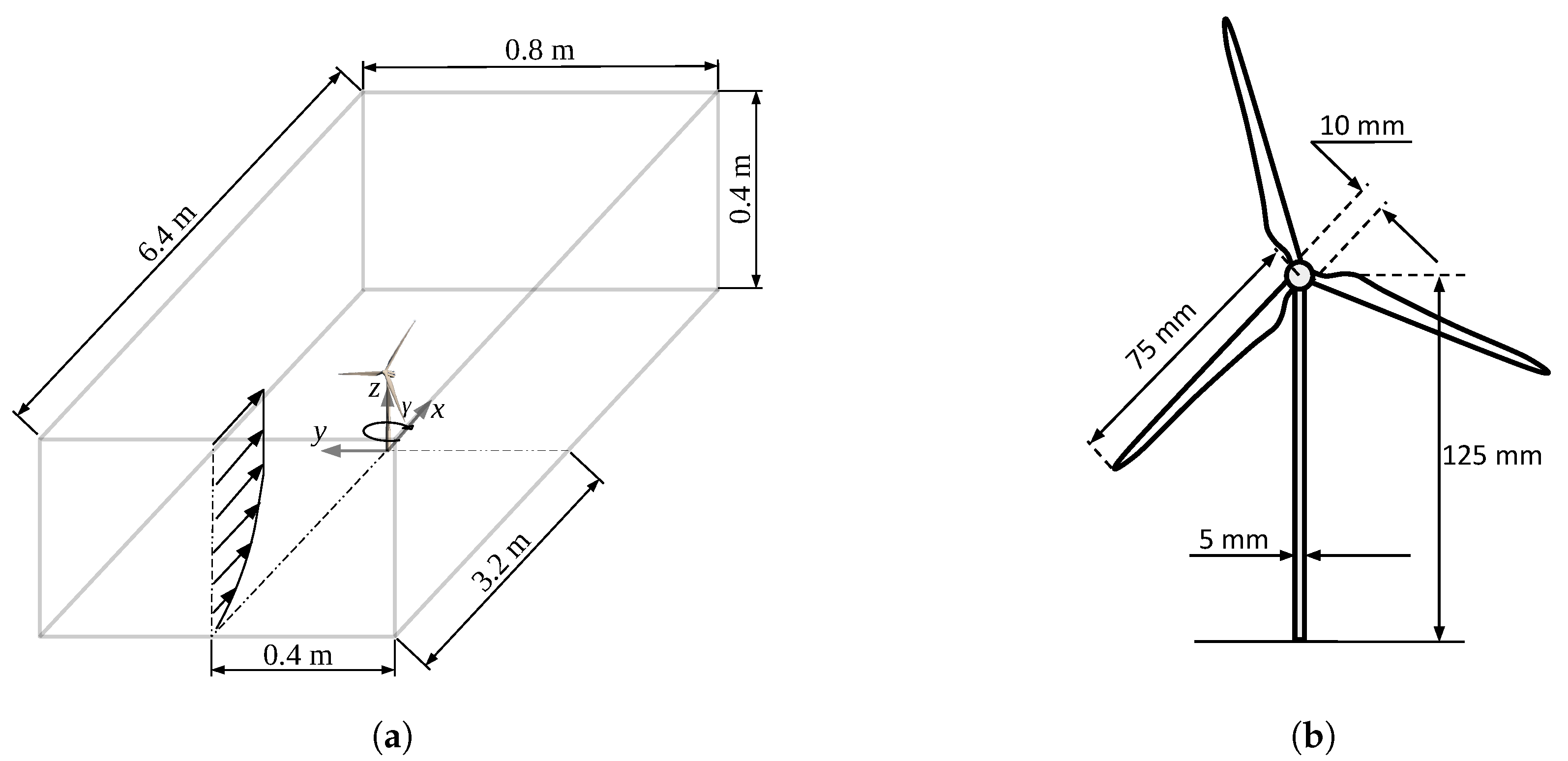
The simulation configuration consists of a fully-developed neutral boundary-layer flow through a stand-alone wind turbine on a flat surface (shown in Figure 2a), which matches the experimental conditions in the wind-tunnel study performed by Bastankhah and Porté-Agel [19]. The main characteristic quantities of the incoming boundary-layer flow measured in the wind tunnel are summarised in Table 1.
The geometric parameters of the miniature wind turbine, WiRE-01 [38], used in the wind-tunnel experiments [19] are shown in Figure 2b. The number of the computational cells in the streamwise (x), spanwise (y) and vertical (z) directions for four cases with different mesh resolution are summarised in Table 2. For all cases, the cells are equidistantly arranged in each direction, which results in 9–24 nodes along the diameter of the wind turbine rotor disk. In the following sections, if not specified, the presented simulation results were obtained from Case 3, with an intermediate resolution.
Periodic boundary conditions are imposed on the lateral boundaries in the x and y directions. On the upper surface of the domain, a frictionless slip-wall boundary condition is applied. On the lower surface, the wall shear stress is specified using the logarithmic law of the wall with local filtered variables, as commonly done in LES studies of ABL flows (e.g., [26,34,39,40]). Specifically, the wall shear stress is computed using the instantaneous filtered velocity at the first u ˜ node above the surface as follows:
τ i 3 | w = u * 2 u ˜ i U a v g = U a v g κ ln ( z / z o ) 2 u ˜ i U a v g , i = 1 , 2 ,
where τ i 3 | w is the instantaneous spatially-filtered wall stress, u * is the local friction velocity, U a v g is the plane-averaged spatially-filtered horizontal velocity, κ = 0.4 is the von Kármán constant, z 0 is the aerodynamic surface roughness length, and z = Δ z / 2 is the vertical distance of the first level of u nodes from the lower surface.
A turbulent inflow condition is generated by a precursor simulation of a fully-developed pressure-driven neutral boundary-layer flow without any wind turbine. The velocity fields of the precursor simulation are enforced as the inflow condition of another simulation, referred to as the “main simulation”. The main simulation has the same numerical setup as the precursor one, but with the wind turbine parameterisation included. A smooth transition function is applied in a buffer zone in front of the enforced inlet in the main simulation to prevent numerical artefacts induced by abrupt changes in the flow. By doing so, the periodic boundary conditions in the horizontal directions can still be used in the main simulation while avoiding re-entries of the wind turbine wake. This method for inflow turbulence generation has been successfully applied in previous LES studies of turbine wakes (e.g., [5,37,41]).

3. Results

3.1. Inflow Conditions

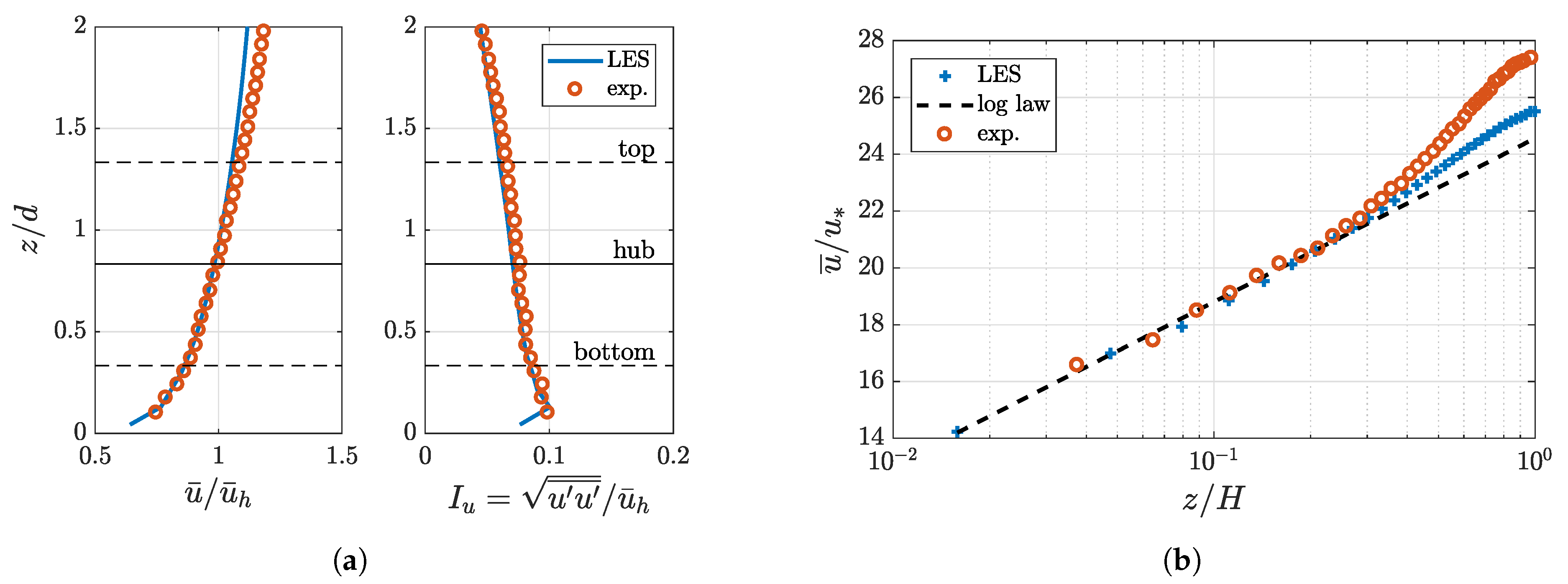
In Figure 3, the vertical profiles of the normalised mean streamwise wind speed and streamwise turbulence intensity obtained from the precursor LES are compared with the wind-tunnel measurements of Bastankhah and Porté-Agel [19]. A good agreement is found between the simulation results and the measurements, proving that inflow conditions similar to the wind-tunnel experiments in Bastankhah and Porté-Agel [19] are created by the precursor simulation.

3.2. Velocity Deficit and Turbulence Intensity Contours

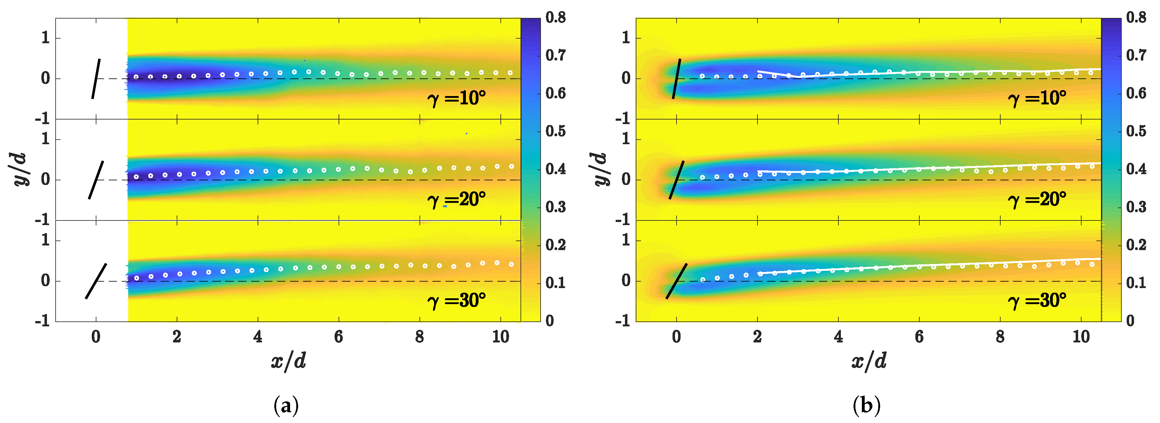
Contours of the normalised mean streamwise velocity deficit Δ u ¯ / u ¯ h u b in the spanwise x-y cross-section plane at the hub height are shown in Figure 4 for yaw angles of 10 , 20 and 30 , respectively. In agreement with the wind-tunnel measurements (Figure 4a), the simulated wakes behind a yawed wind turbine parameterised by the yawed ADMR (Figure 4b) are deflected towards the downstream-inclined side of the rotor disk, and the wake deflection increases with the wind turbine yaw angle. Good agreement is also found between the wake-centre trajectories (defined as the locations of the maximum velocity deficit) obtained from wind-tunnel measurements and those computed from LES results for all yaw angles considered here.
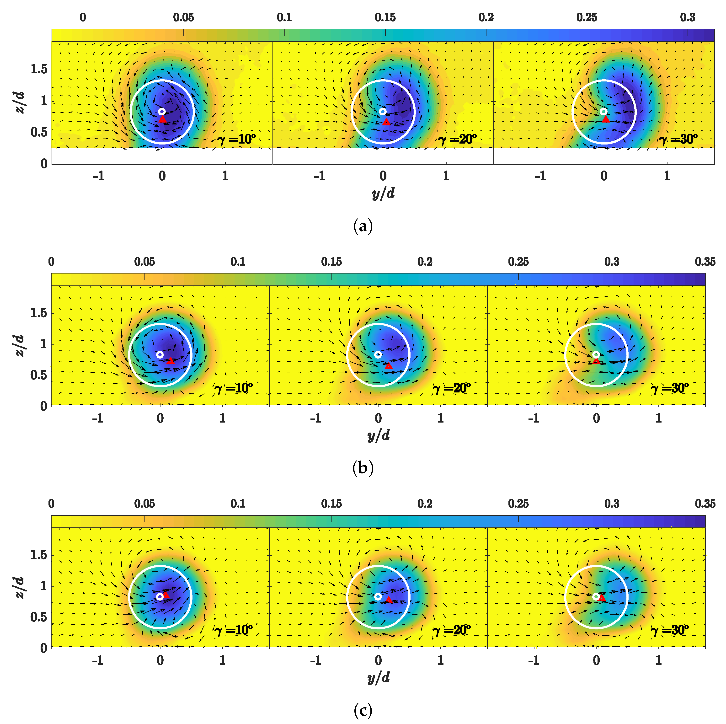
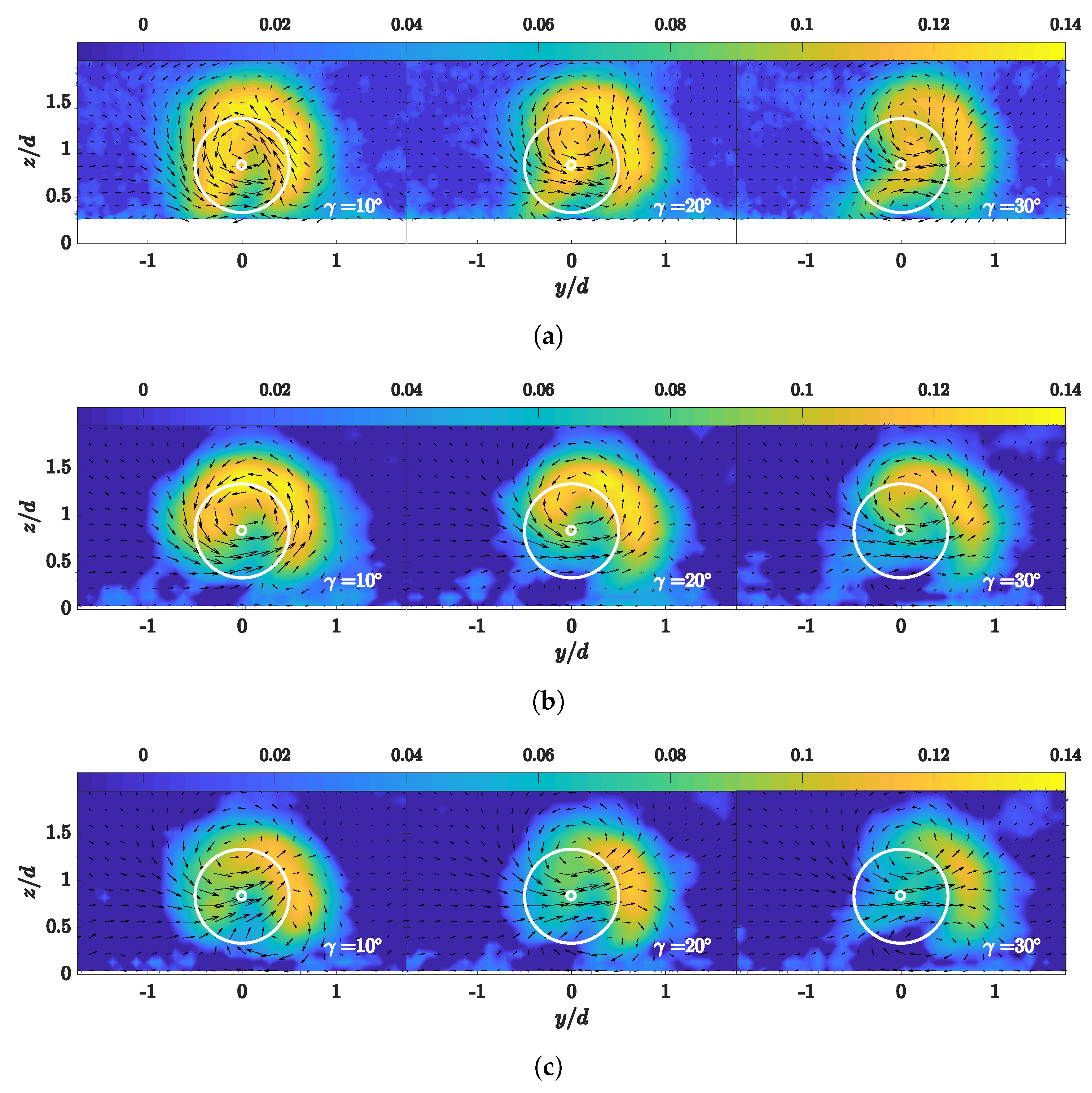
Figure 5 offers another view of the wakes behind the yawed wind turbine in the vertical y-z cross-section plane at the downstream location x / d = 6 , for the three yaw angles under consideration. The contours of the normalised streamwise mean velocity deficit Δ u ¯ / u ¯ h obtained from wind-tunnel measurements and LES using the yawed ADMR and the standard ADM are shown in Figure 5. A kidney-shaped velocity deficit region is found in the wind tunnel measurements (Figure 5a), particularly in the cases of large yaw angles. Such a distinctive kidney shape in the velocity deficit is associated with the presence of a counter-rotating vortex pair (CVP) in the wakes behind yawed wind turbines [19,25]. For the small yaw angle case ( 10 ), the experimental data show that the flow is dominated by the wake rotation. This pattern is well captured by the yawed ADMR, but not by the standard ADM, which produces a CVP largely symmetrical about the turbine hub height. Such a discrepancy occurs because the standard ADM does not exert disk-tangential forces to the flow, thus inducing no wake rotation. For the cases of larger yaw angles ( 20 and 30 ), the CVP becomes more identifiable in the experiment data: it has a larger upper vortex, and the centre of the CVP (the CVP centre is identified as the mid-point of the locations of the maximum and the minimum vorticity computed from the in-plane velocity on the y-z cross-section plane) and the horizontal cross-flow are both below the hub height. These asymmetrical features of the CVP are also reproduced by the yawed ADMR. In contrast, the standard ADM produces a CVP that is overly symmetrical about the hub height. Such results are in agreement with the recent study of yawed turbine wakes performed by Zong and Porté-Agel [42], which highlights the role of wake rotation in the onset and the deformation of the CVP.
Figure 6 shows the added streamwise turbulence intensity I u , a d d in the vertical y-z cross-section plane at the downstream location x / d = 6 , for the three yaw angles under consideration. We observe that, in contrast with the symmetrical horseshoe-shaped distribution of the added streamwise turbulence intensity I u , a d d in non-yawed wind turbine wakes [5], the distribution of I u , a d d in the yawed wind turbine wake is asymmetric, bending towards the side where the wake is deflected to. Comparing to the standard ADM, we found that using the yawed ADMR in LES improves the prediction of the magnitude of the turbulence intensity in the wake, particularly in the upper part. However, the yawed ADMR still underestimates the turbulence intensity in the lower part of the wake. A possible explanation for such discrepancy is that, compared to the upper part of the yawed rotor disk, the blade sections in the lower part encounter larger angles of attack. As a result, the actual aerodynamic lift and drag coefficients ( C L and C D ) of the blade sections in the lower part of the rotor are likely to deviate more from the 2D tabular aerodynamic data used in the parameterisation, compared to those of the blade sections in the upper part.

3.3. Spanwise Velocity Deficit and Turbulence Intensity Profiles

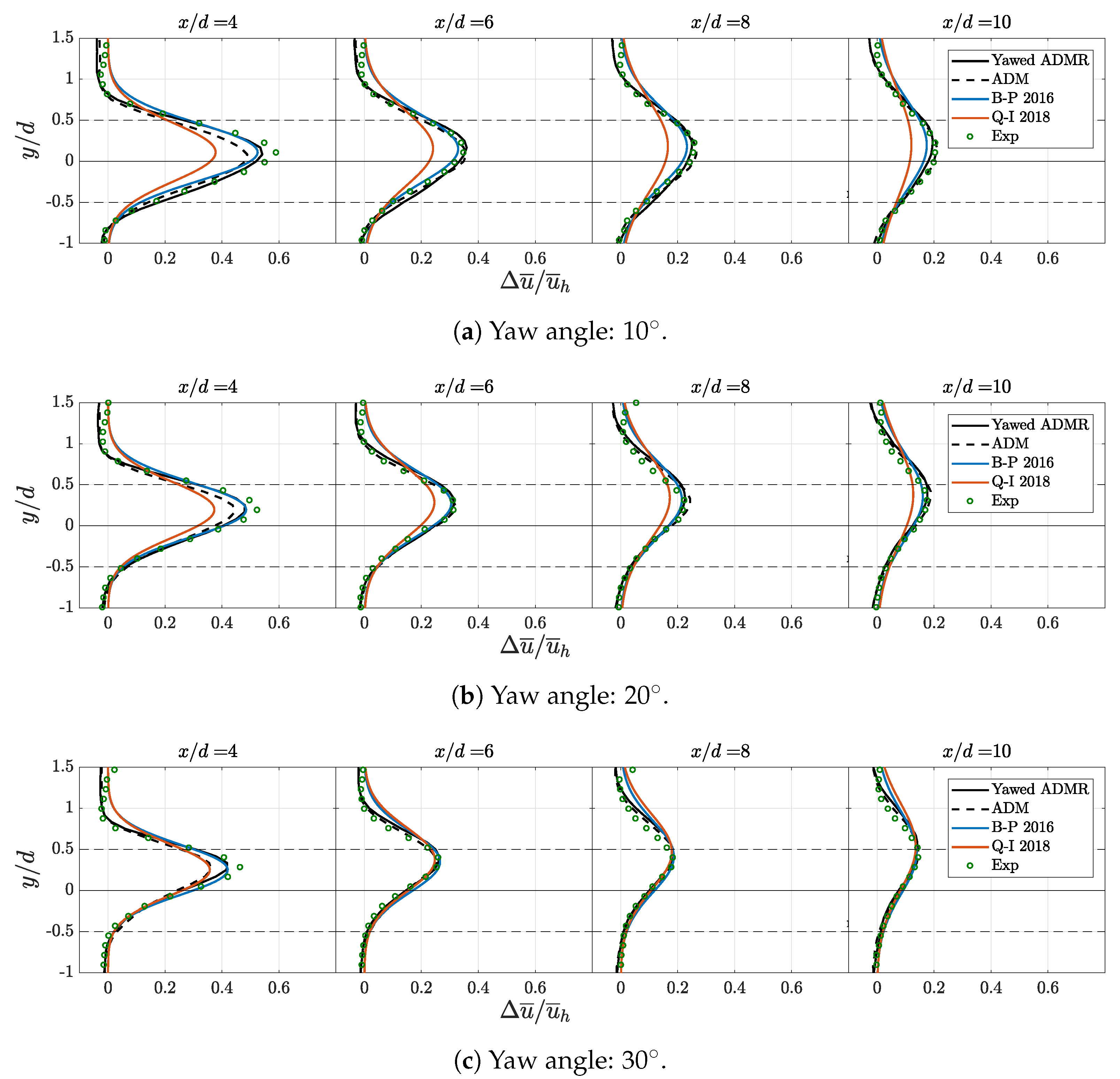
The spanwise profiles of the normalised streamwise velocity deficit for different yaw angles are shown in Figure 7. LES results from the yawed ADMR are compared with wind-tunnel measurements, predictions from the Gaussian-based analytical wake models [19,22], as well as the LES results using the standard ADM. As shown in Figure 7, the LES results using the yawed ADMR are in good agreement with the experimental data, despite small bias towards larger wake deflection. From 6D downstream, good consistency is found in the velocity deficit profiles between the measurements, the predictions of the Bastankhah–Porté-Agel model and the LES results using the two turbine parameterisations considered here. The Qian–Ishihara model underestimates the velocity deficits in the wakes for the cases of 10 and 20 yaw angles.
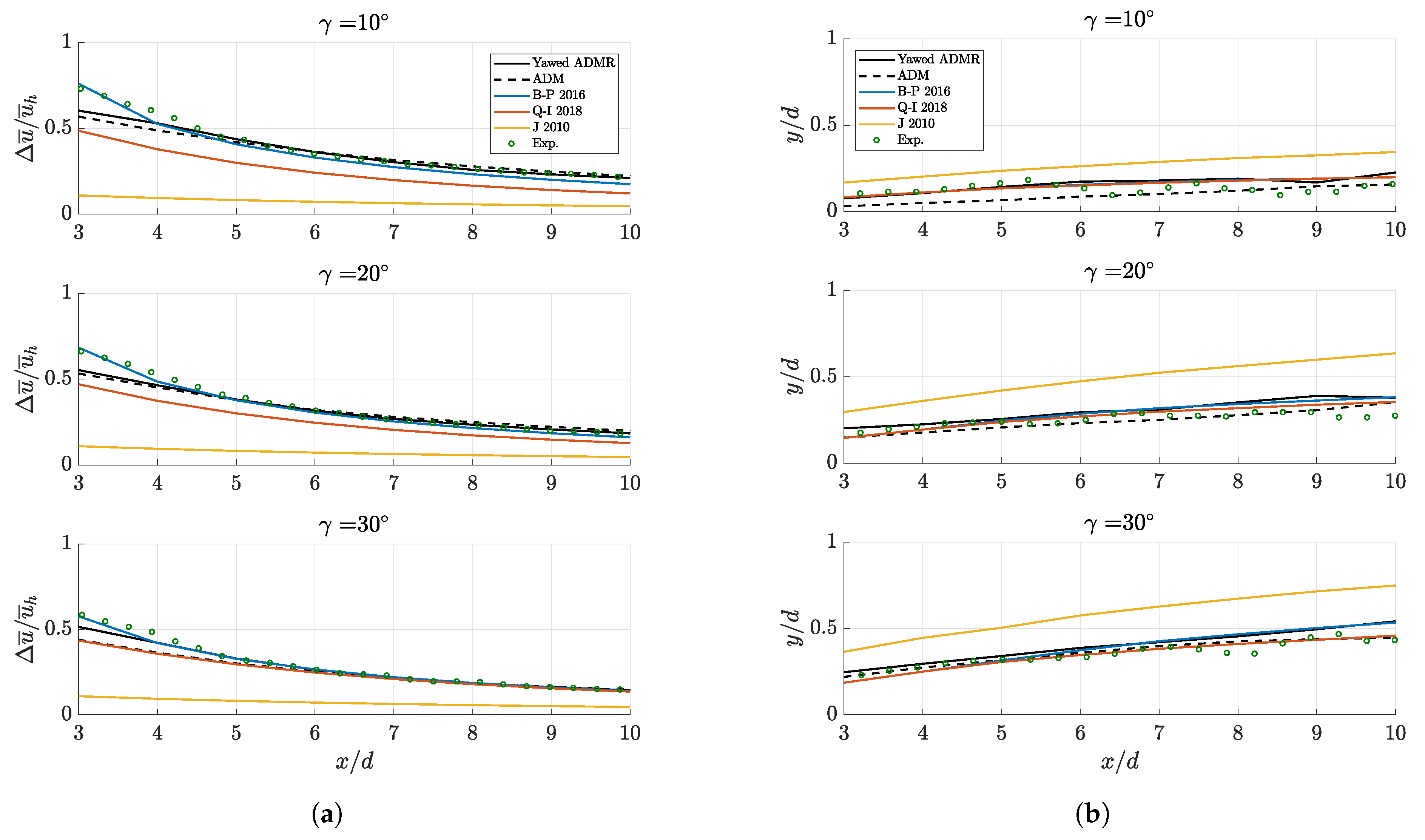
To further illustrate the differences between the LES results, analytical wake model predictions and wind-tunnel measurements, we compare the maximum velocity deficits and the wake-centre locations in Figure 8. One can observe in Figure 8a that, for all yaw angles, the yawed ADMR gives slightly better predictions of the maximum velocity deficit than the standard ADM, which under-predicts the velocity deficit more before x / d = 5 . As the wakes develop further downstream, the LES results gradually converge to the wind-tunnel measurements and are also in good agreement with the Bastankhah–Porté-Agel model, which is formulated to be applied in the far wake region. The Qian–Ishihara model, as we indicated previously, under-predicts the maximum velocity deficit for the cases of 10 and 20 yaw angles. The Jiménez model [12] shows the largest deviation from the experiment results, due to the fact that it assumes a top-hat velocity deficit profile. Figure 8b shows that the Jiménez model also significantly overestimates the wake deflection for all yaw angles considered here. The results from the LES and the other two Gaussian analytical models, in terms of predicting the wake deflection, are in much better agreement with the wind-tunnel measurements. LES using the yawed ADMR exhibits small biases towards overestimating the wake deflections with respect to the measurements, while the standard ADM slightly underestimates the wake deflection in the case of the small yaw angle γ = 10 . A bias similar to the yawed ADMR towards over-predicting the wake deflections is found in the Bastankhah–Porté-Agel model, while the Qian–Ishihara model yields slightly better wake deflection prediction in the cases of γ = 20 and γ = 30 .
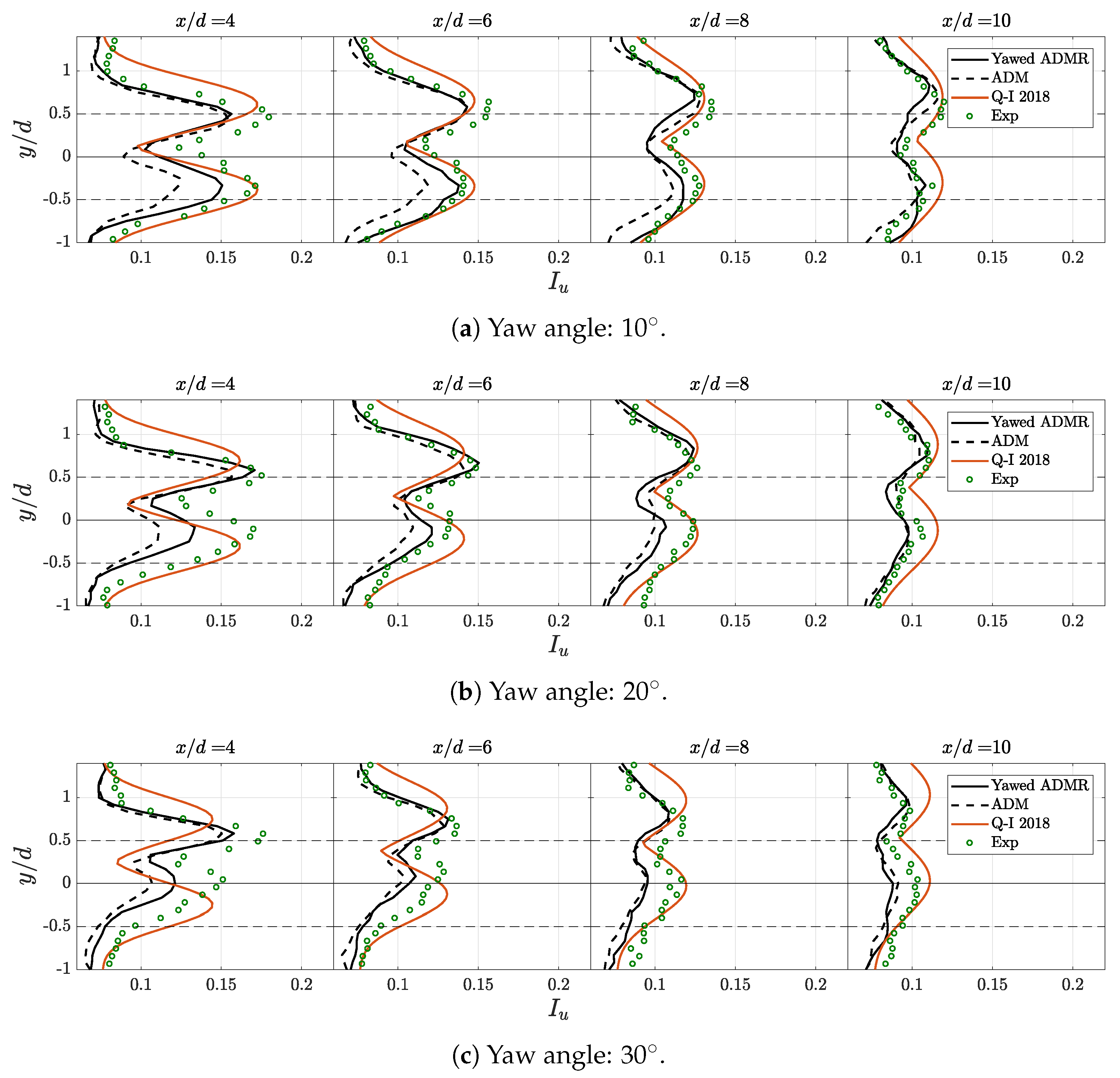
The spanwise profiles of the normalised streamwise turbulence intensity are shown in Figure 9 for the three yaw angles under consideration. LES results using the yawed ADMR and the standard ADM are compared with wind-tunnel measurements and the predictions from the Qian–Ishihara model. The Bastankhah–Porté-Agel model and the Jiménez model are not shown in this plot because they do not provide a prediction for the turbulence intensity distribution in the wake. As shown in Figure 9, the yawed ADMR outperforms the standard ADM in terms of the predictions of turbulence intensity in the wakes up to x / d = 6 , particularly on the side opposite to the wake deflection. The Qian–Ishihara model provides acceptable predictions of the maximum turbulence intensity in the wake for cases with small yaw angles, but it overestimates the spanwise variance of the turbulence intensity distribution. Moreover, the Qian–Ishihara model for the wake turbulence is based on a bimodal Gaussian profile of equal amplitude, which is unable to capture the asymmetric nature of the turbulence in the wakes behind yawed wind turbines revealed by both LES results and wind-tunnel measurements.
Finally, to examine the mesh convergence of the LES results using the yawed ADMR parameterisation, spanwise profiles of the mean streamwise velocity deficit at the hub-height for Cases 1–4 listed in Table 2 are shown in Figure 10. Good mesh convergence is observed for the range of resolution considered in this study. Such observation is in line with the conclusion of previous LES studies of non-yawed wind turbine wakes, which indicate that a resolution with more than seven grid points along the rotor diameter is sufficient for the ADMR parameterisation [5,36] to resolve the wind turbine forces. We also notice that the bias towards larger wake deflection is not eliminated by refining the mesh. We speculate that such a bias could be attributed to some missing phenomena in the near-wake region induced by the yawed ADMR, e.g., tip vortices, that might affect the prediction of the initial wake skew angle.

3.4. Mechanical Power Predictions

To evaluate the ability of the yawed ADMR to predict the power of a yawed wind turbine, we compare the power outputs obtained from LES results using the yawed ADMR and the standard ADM with the power measured in the wind-tunnel experiments. In the case of LES using the yawed ADMR, the mechanical power of the wind turbine is directly obtained from the tangential forces F θ resolved by the yawed ADMR parameterisation on the rotor disk:
P A D M R = ω i = 1 N r i F θ i ,
in which ω = 246.7 rad/s is the rotor angular velocity. r i and F θ i are the distance to the hub-centre and the resolved tangential force of the ith blade element, respectively. In contrast, in the case of LES using the standard ADM, the power extracted by the wind turbine from the incoming flow is estimated indirectly from the rotor-averaged thrust force F x and the rotor-normal flow velocity u d at the wind turbine [13,43,44]:
P A D M = F x u d .
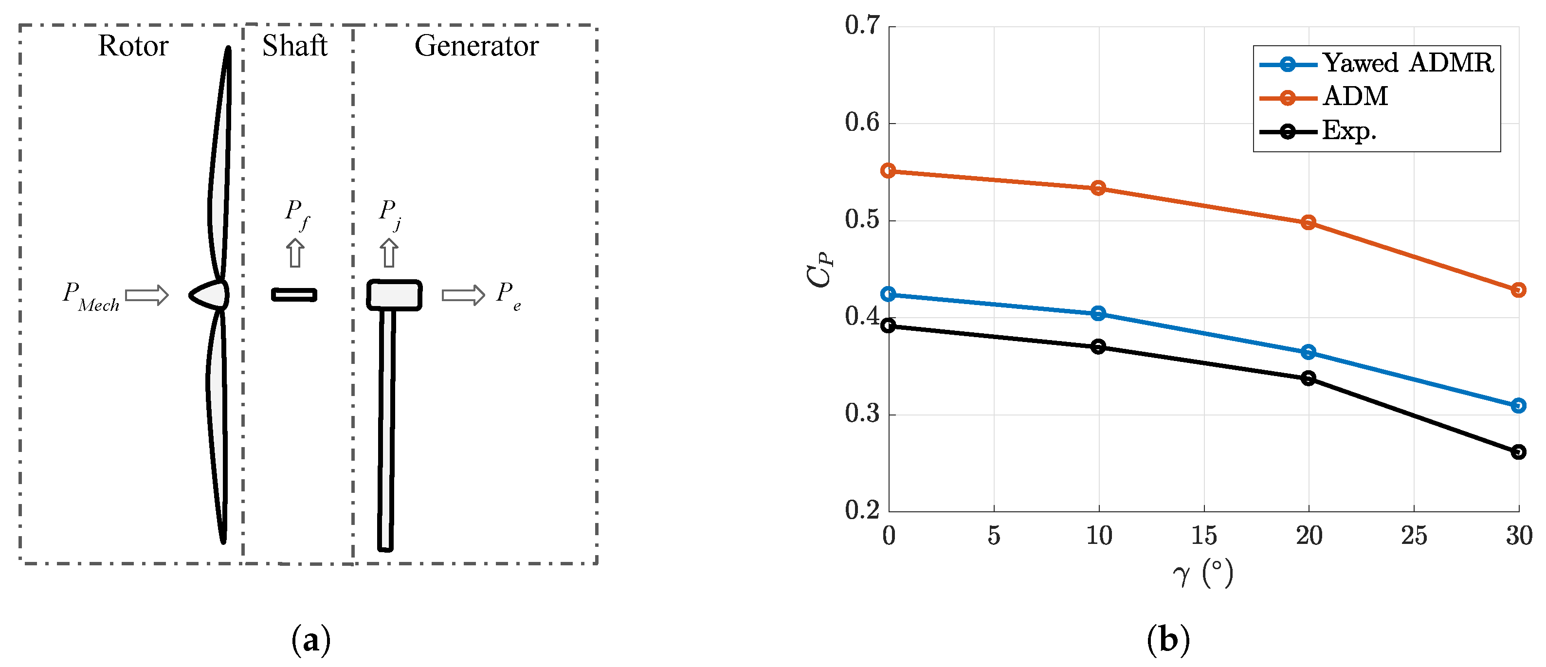
It is worth noting that the mechanical power P M e c h extracted by the miniature wind turbine from the flow is not measured directly in the wind tunnel experiments carried out by Bastankhah and Porté-Agel [19]. Therefore, a conversion is needed to compare with the power output obtained from LES. In the miniature wind turbine under consideration, the mechanical power P M e c h is converted into the electrical power output P e through a shaft and a generator as follows:
P M e c h = P e + P j P c o n v = K I + P f ,
in which P j is the electrical loss in the DC generator due to the electrical resistance and P f is the shaft friction loss. The sum of P e and P j is known as the converted power P c o n v and is computed by the product of the electrical current output I and the torque constant of the generator K [19]. Bastankhah and Porté-Agel [38] later found that, at the optimal tip speed ratio specified in this study ( λ = 3.8 ), the ratio between P c o n v and P M e c h equals 0.92 for this specific miniature wind turbine model, WiRE-01.
The mechanical power extracted by the rotor using both the yawed ADMR parameterisation and the standard ADM without rotation is compared with the mechanical power obtained from the wind-tunnel experiments [19] in Figure 11b. The yawed ADMR shows significant improvement of the power prediction with respect to the standard ADM for all yaw angles. The improvement can be explained by the fact that the yawed ADMR explicitly computes the tangential force component that contributes directly to the torque and, thus, to the mechanical power extracted from the wind by the wind turbine rotor.

4. Summary

In this study, we presented and validated a rotational actuator disk model to parameterise the forces induced by a yawed wind turbine on the flow. By comparing the wind-tunnel measurements, the analytical model predictions and the LES results, we found that the LES using the yawed ADMR, in comparison with the standard ADM without rotation, can provide improved predictions of the mean streamwise velocity deficit and the streamwise turbulence intensity in the yawed turbine wakes. However, a small bias towards overestimating the wake deflection was also observed in the results using the yawed ADMR. The origin of this bias should be the subject of future studies. LES using the yawed ADMR can reproduce the interaction between the wake rotation and the CVP in the vertical y-z cross-section plane of yawed wind turbine wakes, which has been observed in wind-tunnel experiments. The standard ADM, on the other hand, fails to capture such interaction, as no wake rotation is induced by it.
We also found that using the yawed ADMR in LES markedly improves the turbine power prediction in comparison with using the standard ADM, which significantly overestimates the turbine power, compared to the wind tunnel measurements. Such validation of the yawed ADMR on the power prediction is particularly valuable for LES applications in the optimisation-oriented AYC in wind farms. In practice, those applications often require accurate predictions of wind turbine power and wake characteristics, as well as affordable computational costs, allowing the iterative searching of the optimal AYC strategy to be performed. The yawed ADMR validated in this study provides a good option for those applications: besides its ability of reproducing the main characteristics of yawed turbine wakes, the yawed ADMR also computes more realistic wind turbine power than the standard ADM, while avoiding incurring higher computational costs required by the ALM. To the best of our knowledge, this is the first time that such validation of the ADMR for yawed wind turbines is performed.
The wind turbine parameterisation validated in this study can be used to investigate optimal wind farm operation strategies based on the AYC. In the next step, we plan to further apply the LES framework established in this study in multi-wind turbine cases with the AYC. Furthermore, as the forces exerted by the flow on the wind turbine are explicitly computed, the validated turbine parameterisation can also be applied to the joint optimisation of the power and the structural loads in wind farms using the AYC.

Author Contributions

Conceptualisation, M.L. and F.P.-A.; Data curation, M.L.; Formal analysis, M.L.; Funding acquisition, F.P.-A.; Investigation, M.L. and F.P.-A.; Methodology, M.L. and F.P.-A.; Project administration, F.P.-A.; Resources, F.P.-A.; Software, M.L. and F.P.-A.; Supervision, F.P.-A.; Validation, M.L.; Visualisation, M.L.; Writing—original draft, M.L.; and Writing—review and editing, F.P.-A.

Funding

This research was funded by the Swiss Federal Office of Energy (Grant SI/501337-01) and the Swiss National Science Foundation (Grants 200021_172538). In addition, this project was carried out within the frame of the Swiss Centre for Competence in Energy Research on the Future Swiss Electrical Infrastructure (SCCER-FURIES) with the financial support of the Swiss Innovation Agency (Innosuisse—SCCER program, contract number: 1155002544).

Acknowledgments

The authors would like to thank Majid Bastankhah and Jiannong Fang for the helpful discussion on the technical details of the experimental data and the code implementation involved in this study.

Conflicts of Interest

The authors declare no conflict of interest.

References

  1. Stevens, R.J.; Meneveau, C. Flow structure and turbulence in wind farms. Annu. Rev. Fluid Mech. 2017, 49, 311–339. [Google Scholar] [CrossRef]
  2. Porté-Agel, F.; Bastankhah, M.; Shamsoddin, S. Wind-Turbine and Wind-Farm Flows: A Review. Available online: https://doi.org/10.1007/s10546-019-00473-0 (accessed on 7 September 2019).
  3. Lavely, A.W.; Vijayakumar, G.; Craven, B.; Jayaraman, B.; Paterson, E.G.; Nandi, T.N.; Brasseur, J. Towards a blade-resolved hybrid URANS-LES of the NREL 5-MW wind turbine rotor within large eddy simulation of the atmospheric boundary layer. In Proceedings of the 32nd ASME Wind Energy Symposium, National Harbor, MD, USA, 13–17 January 2014; p. 0869. [Google Scholar]
  4. Jiménez, A.; Crespo, A.; Migoya, E.; García, J. Advances in large-eddy simulation of a wind turbine wake. J. Phys. Conf. Ser. 2007, 75, 012041. [Google Scholar] [CrossRef]
  5. Wu, Y.T.; Porté-Agel, F. Large-eddy simulation of wind-turbine wakes: Evaluation of turbine parametrisations. Bound.-Layer Meteorol. 2011, 138, 345–366. [Google Scholar] [CrossRef]
  6. Sørensen, J.N.; Shen, W.Z. Numerical modeling of wind turbine wakes. J. Fluids Eng. 2002, 124, 393–399. [Google Scholar] [CrossRef]
  7. Porté-Agel, F.; Wu, Y.T.; Lu, H.; Conzemius, R.J. Large-eddy simulation of atmospheric boundary layer flow through wind turbines and wind farms. J. Wind. Eng. Ind. Aerodyn. 2011, 99, 154–168. [Google Scholar] [CrossRef]
  8. Sørensen, J.N.; Mikkelsen, R.F.; Henningson, D.S.; Ivanell, S.; Sarmast, S.; Andersen, S.J. Simulation of wind turbine wakes using the actuator line technique. Philos. Trans. R. Soc. A 2015, 373. [Google Scholar] [CrossRef] [PubMed]
  9. Martínez-Tossas, L.A.; Churchfield, M.J.; Leonardi, S. Large eddy simulations of the flow past wind turbines: Actuator line and disk modeling. Wind Energy 2015, 18, 1047–1060. [Google Scholar] [CrossRef]
  10. Stevens, R.J.A.M.; Martínez-Tossas, L.A.; Meneveau, C. Comparison of wind farm large eddy simulations using actuator disk and actuator line models with wind tunnel experiments. Renew. Energy 2018, 116, 470–478. [Google Scholar] [CrossRef]
  11. Porté-Agel, F.; Lu, H.; Wu, Y.T. A large-eddy simulation framework for wind energy applications. In Proceedings of the Fifth International Symposium on Computational Wind Engineering, Chapel Hill, NC, USA, 23–27 May 2010; Volume 23. [Google Scholar]
  12. Jiménez, Á.; Crespo, A.; Migoya, E. Application of a LES technique to characterize the wake deflection of a wind turbine in yaw. Wind Energy 2010, 13, 559–572. [Google Scholar] [CrossRef]
  13. Munters, W.; Meyers, J. Dynamic strategies for yaw and induction control of wind farms based on large-eddy simulation and optimization. Energies 2018, 11, 177. [Google Scholar] [CrossRef]
  14. Boersma, S.; Doekemeijer, B.; Siniscalchi-Minna, S.; van Wingerden, J. A constrained wind farm controller providing secondary frequency regulation: An LES study. Renew. Energy 2019, 134, 639–652. [Google Scholar] [CrossRef]
  15. Fleming, P.; Annoni, J.; Churchfield, M.; Martinez-Tossas, L.A.; Gruchalla, K.; Lawson, M.; Moriarty, P. A Simulation Study Demonstrating the Importance of Large-Scale Trailing Vortices in Wake Steering; Technical Report; National Renewable Energy Lab. (NREL): Golden, CO, USA, 2018.
  16. Fleming, P.A.; Gebraad, P.M.O.; Lee, S.; van Wingerden, J.W.; Johnson, K.; Churchfield, M.; Michalakes, J.; Spalart, P.; Moriarty, P. Evaluating techniques for redirecting turbine wakes using SOWFA. Renew. Energy 2014, 70, 211–218. [Google Scholar] [CrossRef]
  17. Wang, J.; Foley, S.; Nanos, E.M.; Yu, T.; Campagnolo, F.; Bottasso, C.L.; Zanotti, A.; Croce, A. Numerical and experimental study of wake redirection techniques in a boundary layer wind tunnel. J. Phys. Conf. Ser. 2017, 854, 012048. [Google Scholar] [CrossRef]
  18. Jensen, N.O. A Note on Wind Generator Interaction; Risø National Laboratory: Roskilde, Denmark, 1983. [Google Scholar]
  19. Bastankhah, M.; Porté-Agel, F. Experimental and theoretical study of wind turbine wakes in yawed conditions. J. Fluid Mech. 2016, 806, 506–541. [Google Scholar] [CrossRef]
  20. Bastankhah, M.; Porté-Agel, F. A new analytical model for wind-turbine wakes. Renew. Energy 2014, 70, 116–123. [Google Scholar] [CrossRef]
  21. Shapiro, C.R.; Gayme, D.F.; Meneveau, C. Modelling yawed wind turbine wakes: A lifting line approach. J. Fluid Mech. 2018, 841, R1. [Google Scholar] [CrossRef]
  22. Qian, G.W.; Ishihara, T. A New Analytical Wake Model for Yawed Wind Turbines. Energies 2018, 11, 665. [Google Scholar] [CrossRef]
  23. Martínez-Tossas, L.A.; Annoni, J.; Fleming, P.A.; Churchfield, M.J. The aerodynamics of the curled wake: A simplified model in view of flow control. Wind Energy Sci. 2019, 4, 127–138. [Google Scholar] [CrossRef]
  24. Bay, C.; King, J.; Fleming, P.; Mudafort, R. Unlocking the Full Potential of Wake Steering: Implementation and Assessment of a Controls-Oriented Model; Technical report; National Renewable Energy Lab. (NREL): Golden, CO, USA, 2019.
  25. Howland, M.F.; Bossuyt, J.; Martínez-Tossas, L.A.; Meyers, J.; Meneveau, C. Wake structure in actuator disk models of wind turbines in yaw under uniform inflow conditions. J. Renew. Sustain. Energy 2016, 8, 043301. [Google Scholar] [CrossRef]
  26. Porté-Agel, F.; Meneveau, C.; Parlange, M.B. A scale-dependent dynamic model for large-eddy simulation: Application to a neutral atmospheric boundary layer. J. Fluid Mech. 2000, 415, 261–284. [Google Scholar] [CrossRef]
  27. Stoll, R.; Porté-Agel, F. Dynamic subgrid-scale models for momentum and scalar fluxes in large-eddy simulations of neutrally stratified atmospheric boundary layers over heterogeneous terrain. Water Resour. Res. 2006, 42. [Google Scholar] [CrossRef]
  28. Revaz, T.; Lin, M.; Porté-Agel, F. Aerodynamic Data of WiRE-01 Blade. 2019. Available online: https://zenodo.org/record/3460877#.XdyLmtK-uUk (accessed on 25 September 2019).
  29. Sørensen, J.N.; Shen, W.Z.; Munduate, X. Analysis of wake states by a full-field actuator disc model. Wind Energy 1998, 1, 73–88. [Google Scholar] [CrossRef]
  30. Mikkelsen, R. Actuator Disc Methods Applied to Wind Turbines; Technical University of Denmark: Kongens Lyngby, Denmark, 2003. [Google Scholar]
  31. Smith, R.A.; Moon, W.T.; Kao, T. Experiments on flow about a yawed circular cylinder. J. Basic Eng. 1972, 94, 771–776. [Google Scholar] [CrossRef]
  32. Wei, T.; Willmarth, W. Static Pressure Distribution on Long Cylinders as Function of Angle of Yaw and Reynolds Number; Technical Report; Department of Aerospace Engineering, University of Michigan: Ann Arbor, MI, USA, 1983. [Google Scholar]
  33. Moin, P.; Kim, J. Numerical investigation of turbulent channel flow. J. Fluid Mech. 1982, 118, 341–377. [Google Scholar] [CrossRef]
  34. Moeng, C.H. A large-eddy-simulation model for the study of planetary boundary-layer turbulence. J. Atmos. Sci. 1984, 41, 2052–2062. [Google Scholar] [CrossRef]
  35. Biringen, S. Active control of transition by periodic suction-blowing. Phys. Fluids 1984, 27, 1345–1347. [Google Scholar] [CrossRef]
  36. Wu, Y.T.; Porté-Agel, F. Atmospheric turbulence effects on wind-turbine wakes: An LES study. Energies 2012, 5, 5340–5362. [Google Scholar] [CrossRef]
  37. Wu, Y.T.; Porté-Agel, F. Simulation of turbulent flow inside and above wind farms: Model validation and layout effects. Bound.-Layer Meteorol. 2013, 146, 181–205. [Google Scholar] [CrossRef]
  38. Bastankhah, M.; Porté-Agel, F. A New Miniature Wind Turbine for Wind Tunnel Experiments. Part I: Design and Performance. Energies 2017, 10, 908. [Google Scholar] [CrossRef]
  39. Chow, F.K.; Street, R.L.; Xue, M.; Ferziger, J.H. Explicit filtering and reconstruction turbulence modeling for large-eddy simulation of neutral boundary layer flow. J. Atmos. Sci. 2005, 62, 2058–2077. [Google Scholar] [CrossRef]
  40. Allaerts, D.; Meyers, J. Large eddy simulation of a large wind-turbine array in a conventionally neutral atmospheric boundary layer. Phys. Fluids 2015, 27, 065108. [Google Scholar] [CrossRef] [Green Version]
  41. Churchfield, M.J.; Lee, S.; Michalakes, J.; Moriarty, P.J. A numerical study of the effects of atmospheric and wake turbulence on wind turbine dynamics. J. Turbul. 2012, 13. [Google Scholar] [CrossRef]
  42. Zong, H.; Porté-Agel, F. A point vortex transportation model for yawed wind turbine wakes. J. Fluid Mech. 2019. submitted. [Google Scholar]
  43. Hansen, M.O. Aerodynamics of Wind Turbines; Routledge: Abingdon, UK, 2015. [Google Scholar]
  44. Munters, W.; Meyers, J. An optimal control framework for dynamic induction control of wind farms and their interaction with the atmospheric boundary layer. Philos. Trans. R. Soc. A 2017, 375. [Google Scholar] [CrossRef] [Green Version]
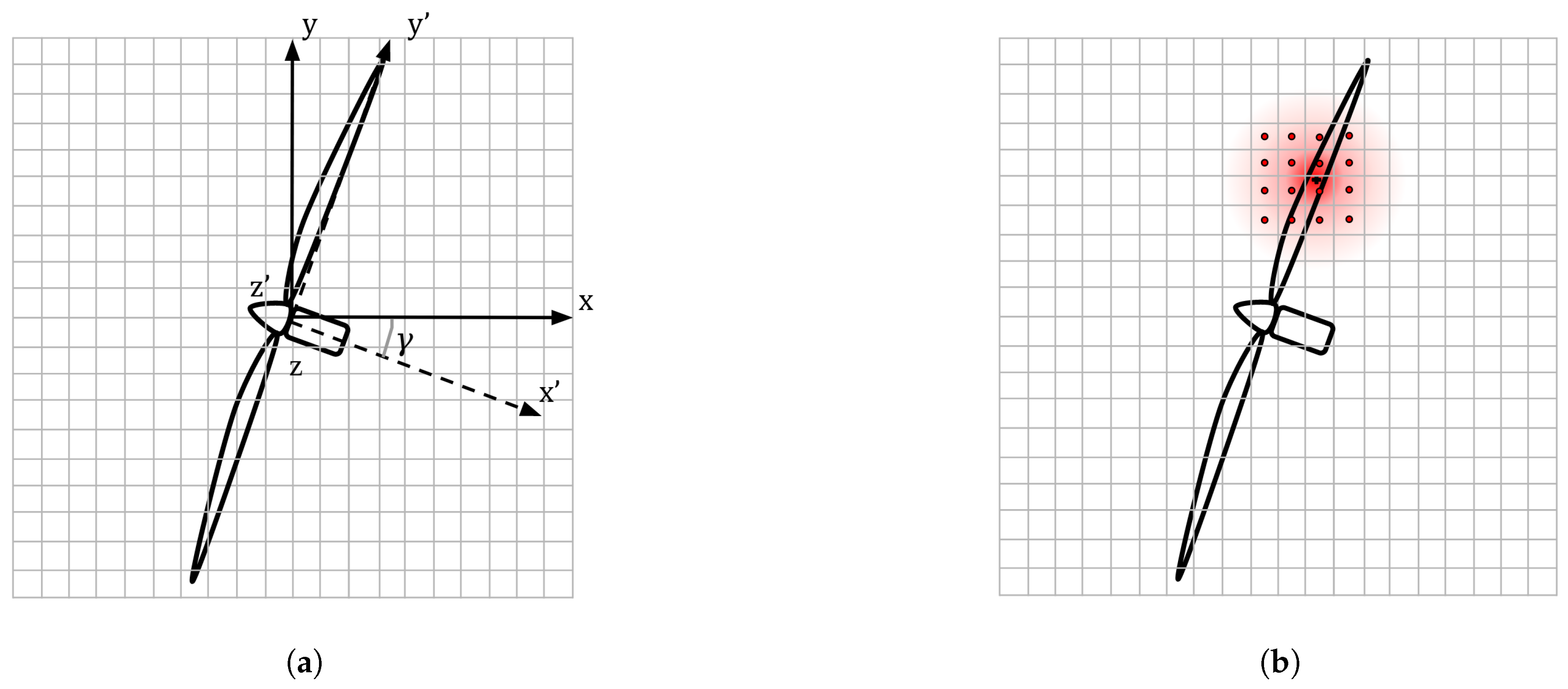
Figure 1. (a) Reference-frame transformation from mesh-aligned ( x , y , z ) to rotor-normal ( x , y , z ) for a wind turbine of a yaw angle γ ; and (b) force smearing from blade element to the neighboring computational cells.
Energies 12 04574 g001
Figure 2. (a) Schematic plot of the simulation domain; and (b) schematic plot of the WiRE-01 miniature wind turbine.
Energies 12 04574 g002
Figure 3. (a) Vertical profiles of the normalised mean streamwise velocity component u ¯ / u ¯ h and the streamwise turbulence intensity I u ; and (b) log-law velocity profile plotted against the vertical profiles of the mean streamwise velocity component normalised by the friction velocity u * .
Energies 12 04574 g003
Figure 4. Contours of the normalised streamwise mean velocity deficit Δ u ¯ / u ¯ h in the spanwise x-y cross-section plane at the hub height obtained from: (a) the wind-tunnel experiments; and (b) the LES using the yawed ADMR. The wake-centre trajectories are represented by white circles for the experiment results and by white solid lines for the simulation results.
Energies 12 04574 g004
Figure 5. Contours of the normalised streamwise velocity deficit Δ u ¯ / u ¯ h for different yaw angles γ , overlapped with vector fields of the in-plane velocity in the vertical y-z cross-section plane at x / d = 6 : (a) wind-tunnel measurements; (b) LES using the yawed ADMR; and (c) LES using the standard ADM. White circles outline the edges of the non-yawed turbine rotor. Red triangles outline the locations of the CVP centre.
Energies 12 04574 g005
Figure 6. Contours of the added streamwise turbulence intensity I u , a d d for different yaw angles γ , superimposed with vector fields of the in-plane velocity in the vertical y-z cross-section plane at x / d = 6 : (a) wind-tunnel measurements; (b) LES using the yawed ADMR; and (c) LES using the standard ADM. White circles outline the edges of the non-yawed turbine rotor.
Energies 12 04574 g006
Figure 7. Spanwise profiles of the normalised mean streamwise velocity deficit Δ u ¯ / u ¯ h : LES using the yawed ADMR (black solid line), LES using the standard ADM (black dashed line), wind-tunnel measurements (green circles), the Bastankhah-Porté-Agel model (blue solid line), and the Qian–Ishihara model (red solid line).
Energies 12 04574 g007
Figure 8. Comparisons of LES results and analytical wake model predictions with respect to wind-tunnel measurements: (a) maximum velocity deficit; and (b) wake-centre location.
Energies 12 04574 g008
Figure 9. Spanwise profiles of the streamwise turbulence intensity I u : LES using the yawed ADMR (black solid line), LES using the standard ADM (black dashed line), wind-tunnel measurements (green circles), and the Qian–Ishihara Model (red solid line).
Energies 12 04574 g009
Figure 10. Spanwise profiles of the normalised mean streamwise velocity deficit Δ u ¯ / u ¯ h . of the wake behind a wind turbine with a yaw angle γ = 20 , obtained from the LES using the yawed ADMR using different mesh resolution.
Energies 12 04574 g010
Figure 11. (a) Conversion of power in the miniature wind turbine model: Mechanical power P M e c h , Shaft friction loss P f , Electrical loss P j and Electrical power P e . (b) Mechanical power coefficient C p for yaw angles 0 30 obtained from the LES results and the wind-tunnel experiments.
Energies 12 04574 g011
Table 1. Main characteristics of the incoming boundary-layer flow.
Inflow CharacteristicValue
Boundary-layer height (H)0.4 m
Hub-height incoming velocity ( u ¯ h )4.88 m/s
Hub-height turbulence intensity ( I u )7%
Surface roughness length ( z o )0.022 mm
Friction velocity ( u * )0.22 m/s
Table 2. Mesh resolution of different simulation cases. N d , y and N d , z represent the numbers of cells covering the turbine rotor in the y and z directions, respectively, in the non-yawed case.
Case No. N x N y N z N d , y N d , z
1256128642424
212864641224
312864321212
496482499