1. Introduction
To comply with the requirements of the energy efficiency design index (EEDI), the shipping industry must find ways to reduce its emissions of greenhouse gases. Low-carbon-emission shipping strategies and technologies that recently have been applied on ships in many developed countries include ship form optimization, electrical propulsion, nuclear propulsion, fuel cells, biomass fuels, and renewable energy sources [
1,
2].
Solar energy is an important natural resource, utilized mainly through photo-thermal and photovoltaic (PV) techniques, which are widely applied in aerospace, architecture, electrical power generation, and elsewhere [
3,
4,
5,
6,
7,
8,
9,
10,
11,
12]. Solar PV technology has been introduced into ships’ power systems to reduce their greenhouse gas emissions, improve energy efficiency, and reinforce power system stability [
13]. PV technology is mainly used in four ways on ships: as a propulsion power supply for small ships, a power supply for a ship’s auxiliary machinery, a supply for general power consumption on large and medium passenger ships, and a heating source for large oil tankers [
3].
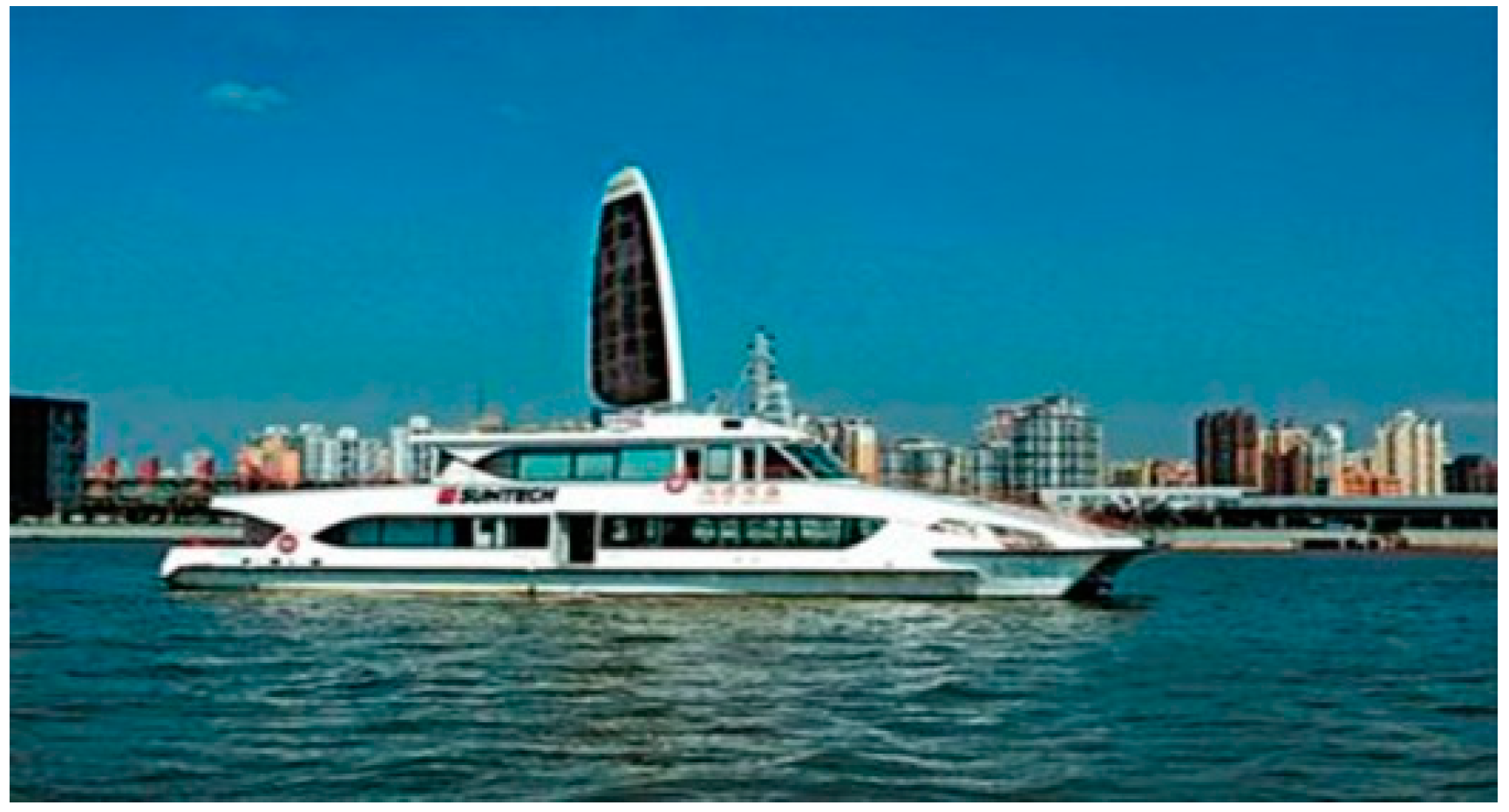
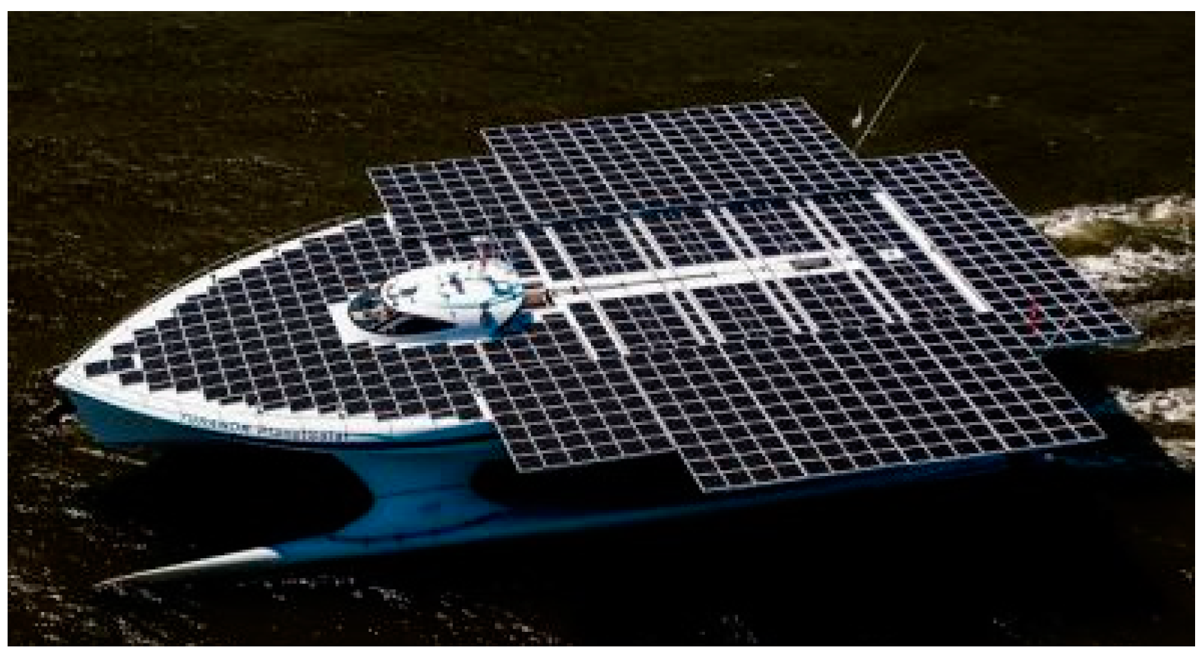
Figure 1 shows the solar cruise ship “Shangdeguosheng”, which was built for the Shanghai World Expo in 2010. Passengers can enjoy a life of leisure on the ship, such as dining and entertainment, and the ship can be used to hold important business meetings and for other functions. In 2011, the German ship “Planet Solar” was constructed (
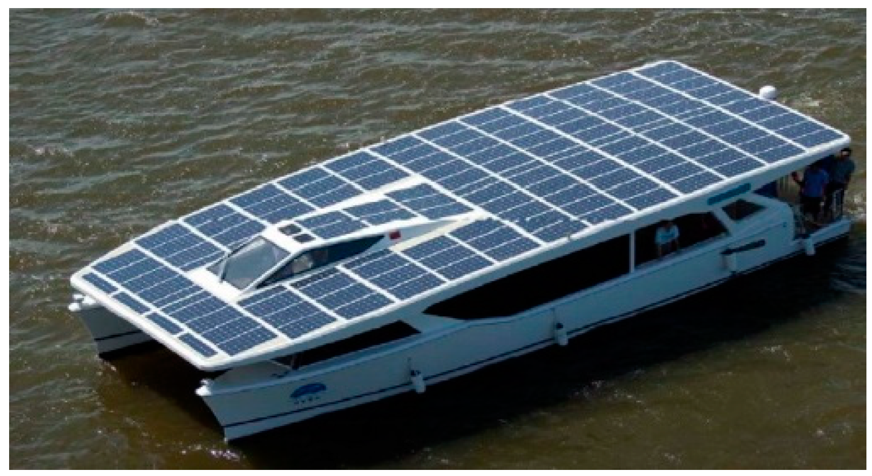
Figure 2), with its owner claiming it to be the world’s largest solar-powered ship. In 2013, the sightseeing ship “Yun Dang No. 1” was navigated in Xiamen Yun Dang Lake, powered by solar energy (
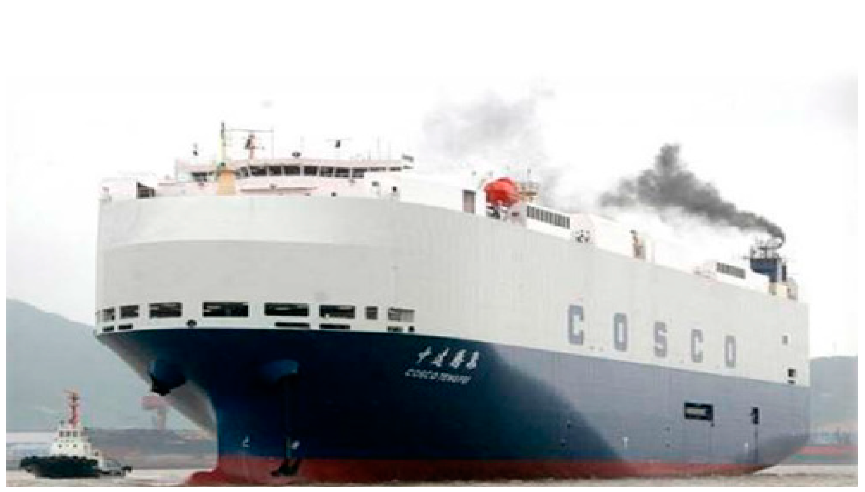
Figure 3). The “Cosco Tengfei” was remodeled to become China’s first large automobile ro-ro ship with solar PV, shown in
Figure 4.
Although PV technology is widely utilized in power systems on land, to the best of our knowledge, hybrid PV/diesel/battery power systems on ships have not been extensively investigated and developed, especially the use of marine micro-grid technology to manage and control hybrid power systems on ships. Glykaset et al. discussed PV systems applied to merchant marine vessels to reduce fuel costs [
14]. A stability assessment and economic analysis of a hybrid PV/DG ship system are presented by Tsekouras et al. [
15]. Adamo et al. offered a preliminary analysis of reducing the emissions from an electrical ship in a berth [
16]. Thus, Wen et al. performed a cost analysis using a particle swarm optimization algorithm to find the optimal size and capacity for various types of energy storage systems [
17]. And, Lan et al. proposed a method for determining the ideal size for a PV power generation system; a diesel generator and an energy storage system were designed in a ship’s stand-alone power system with the aim of minimizing investment cost, fuel cost, and CO
2 emissions [
13].
Tang [
18] proposed a novel structure for a large-scale PV array and its controls, designed for the illumination unit of a ship’s power grid. Lee et al. [
19] reported on the experimental results from the operation of a prototype green ship on Geoje Island, South Korea. In [
20], Sun and colleagues built a simulation model of a PV-driven power system for a ship, based on a PSCAD/EMTDC platform. The use of new energy technologies in ships has so far been limited to the development of “green” touring vessels.
Yu et al. had developed multi-energy ship micro-grid energy control system based on solar lithium battery and diesel generator set for cruise ships and proposed the energy distribution control strategy according to the requirements of safe and stable operation, and they had verified the feasibilities on the actual ships [
21,
22]. Banaei et al. conducted a study on all-electrical propulsion ships, which consisted of fuel cells, batteries, PV, and two diesel generators [
23]. The battery state of charge (SOC) was divided into three different states, in which SOC > SOC
high, SOC
low < SOC < SOC
high, and SOC < SOC
low. They also proposed the different energy management strategies in different states, for that the diesel generators, energy storage systems, and fuel cells were rationally utilized. For the ship’s micro-grid composing of diesel generator and other energy systems, Kuo et al. had proposed a storage for the ship’s power supply mode. The proposed storage could be determined according to the SOC state of energy storage system and it achieved the effects of reducing the fuel consumptions and exhausted emissions of the diesel engine [
24].
However, all of above statements were investigated for the managements of energy sources in static situations, and no dynamic situations were studied. Until now, only few studies were focused on the dynamic control of ship’s micro-grid, but there were many related researches on terrestrial micro-grid. Kong et al. proposed a three-stage proportional plus derivative control (PD) preemptive dynamic scheduling strategy, which could overcome the problem of dynamic control and the PD control was easy to cause oscillation, but the settings of three time constants increased the difficulty of system design [
25]. Because the different micro-grid systems have different time constants, so it is not an almighty method. Ding et al. proposed a method based on fuzzy control strategy for battery energy storage system to improve the transient stability of power grid at when the input of fuzzy controller had the problem of frequency difference [
26]. Above two methods were investigated to suppress the frequency difference, but both would cause a delay in control. Li analyzed the mathematical model of diesel generator, and he obtained the reason of frequency fluctuation during load abrupt change [
27]. Also, Li had proposed the active compensation strategy of current feed forward compensation and PD control algorithm, but this method was easy to cause the high frequency oscillation.
These applications often have shortcomings, such as frequency fluctuation, high cost, and complicated control systems. We therefore propose management and distribution strategies for dynamic power by combining PV, diesel generator, and lithium battery. Via the fuzzy control and compensation method of the ship’s micro-grid system, we were able to obtain optimal compensation power. After taking into consideration the balance between sailing mileage and economic efficiency, as well as how to integrate PV, DG, and lithium battery characteristics, we investigated a ship’s micro-grid system to combine those three power sources. Therefore, this investigated article was based on the dynamic research of terrestrial micro-grid, which combined with the characteristics of the static power allocation strategy and dynamic power allocation strategy of ship’s micro-grid. The strategies for the frequency fluctuation during the sudden change of load in the PV-diesel generator-battery operation mode were analyzed and investigated. The characteristics of the energy storage system could be utilized to respond quickly, and the output or developed power could be used to lower down the frequency fluctuation, and a dynamic energy scheduling strategy was put forward based on current the feed-forward and fuzzy control.
2. Modelling of the Ship’s Micro-Grids System
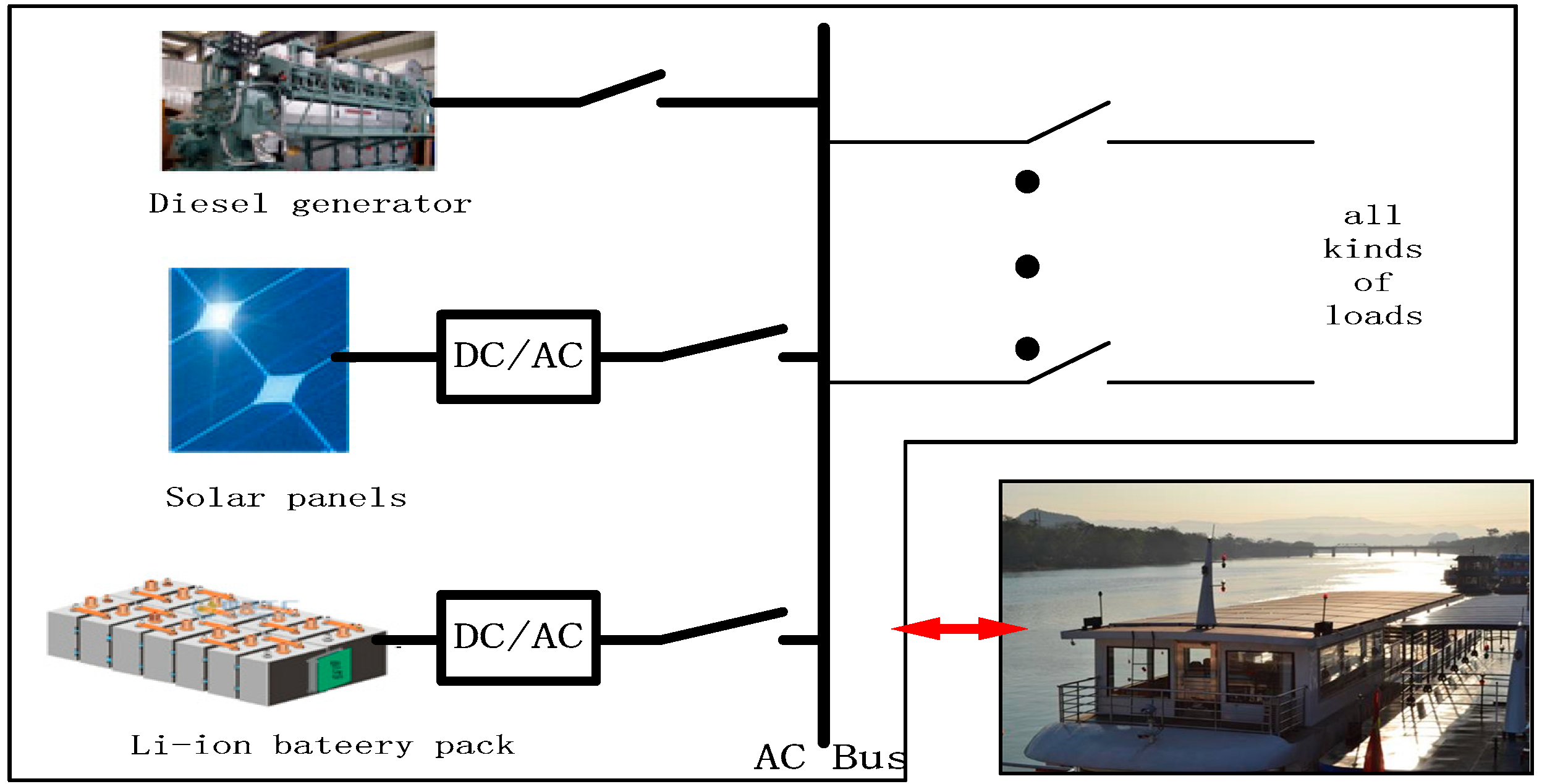
Unlike in previous studies, we considered step changes in strong coupling, the great complexity of the random changes that occur in a ship’s power system, and step changes in loads. We then present a novel dynamic power distribution strategy for a ship’s micro-grid system. The topological structure is shown in
Figure 5 and can be described as follows [
28,
29]:
- (1)
The ship’s micro-grid system is composed of a diesel generator, a lithium battery, and PV solar cells, and the PV and lithium-ion-based battery are connected by inverters to the AC grid bus, which can supply power in parallel with the diesel generator.
- (2)
To use the renewable energy more effectively, the micro-grid power system is mainly operated by the inverter, while the diesel generators are used as an auxiliary or emergency power source.
- (3)
The micro-grid system has many operation modes, depending on the ship’s navigation state. For example, when the ship is in berth with sufficient sunlight, solar power will charge the lithium battery and supply power for the daily living equipment, and the diesel generator will be idle. When the ship is under normal sailing conditions and the voyage is short, propeller power and daily living power will be jointly supplied by the solar and lithium batteries, and the diesel generator will remain idle. When the ship is under normal sailing conditions and the voyage is long, propeller power and living power will be jointly supplied by the solar and lithium batteries, and the diesel generator and energy management control strategy for the ship’s micro-grid system will work together, which is the primary working mode investigated in this paper.
The ship’s micro-grid system is very different from a traditional land micro-grid system, as the ship’s has no unified dispatch center and the operating conditions are more complicated. In the topology described above, one of the frequent operation modes is very complex because the multiple power sources are arranged in parallel. To better analyze the micro-grid system’s performance in this mode, using mathematical analysis of the power supply mechanisms for the various energy sources, we established a simulation model of the micro-grid system. This provides the foundation for further research on the strategy for controlling the micro-grid system under changing dynamic loads.
2.1. The Dynamic Characteristics of the Diesel Generator
The electromagnetic torque formula of for the synchronous generator can be expressed as Equation (1) as when the salient effect is ignored:
In this formula, Ep’ is the instantaneous electromotive force (EMF) of the generator and ip is the stator current of the p axis. The diesel motor drives the synchronous generator’s rotation, and the stator winding of the synchronous generator takes the induction EMF by cutting the magnetic line motion in the magnetic field, providing electrical energy in the case of an external load. When the load alters suddenly, so does its active current. According to Equation (1), the electromagnetic torque also changes.
According to [
30], the functioning of an output diesel-engine speed-control system can be expressed as:
where
M =
Tjs2(1 +
T1s)(1 +
T4s)(1 +
T5s)(1 +
Tds)
+ K(1 +
T2s)(1+
T3s), and
T1,
T4,
T5, and
Td are the small time constants,
Tj is a time constant in the diesel engine model, K refers to the parameter of transfer function, subscript symbol
s refers to the Laplace transform of model, and
Te refers to the electromagnetic torque. If we set
T =
T1 + T4 + T5 + Td, then
M =
Tjs2(1 +
Ts)
+ K(1 +
T2s)(1 +
T3s). Thus, the output of the system can be expressed as:
From Equation (3) we see that the output is determined by the system input volume
ωref(
s) and
Te(
s). The transfer function
ωref(
s) = 0 can be obtained under load disturbance. The transfer function G(s) can be then expressed as:
2.2. The Model of the PV Cells
PV cells are semiconductor devices based on the PV effect of semiconducting materials with a PN junction and have the function of directly converting sunlight into electrical energy. According to [
31], when sunlight shines on PV cells, the electrons in the P region move to the N region, resulting in a large amount of electrons accumulating on the receivers.
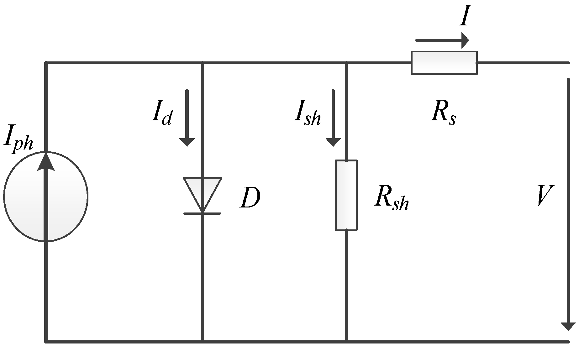
The PV battery equivalent circuit model is shown in
Figure 6, where
Iph is a photo-generated current whose magnitude depends on the light intensity
S and temperature
T, and which acts as a controlled current source;
Id is a voltage generated by a reactive PN junction of voltage
V;
Ish is the short-circuit current caused by leakage from the PV cells;
Rs and
Rsh are the series resistance and parallel resistance of the PV cells;
V is the PV output voltage; and
I is the PV output current. The output current of the PV cells can be obtained from the equivalent circuit diagram and Equation (5):
In Equation (5),
Iph is the photo current;
Ios is the diode reverse saturation current;
q is the electron constant, 1.602 × e
–19(C);
V and
I are the PV output voltage and current;
Rs is the series resistance;
Rsh is the parallel resistance;
A is the diode characteristic fitting coefficient;
K is the Boltzmann constant, with a value of 1.831 × e
–23(J/K);
T is the PV cell working temperature in Kelvin;
Iscr is the short-circuit current under the conditions of solar radiation intensity
Sr = 1000W/m
2 and temperature
Tr = 25°C;
ki is the short-circuit current temperature coefficient;
Ior is the dark saturation current under
Tr;
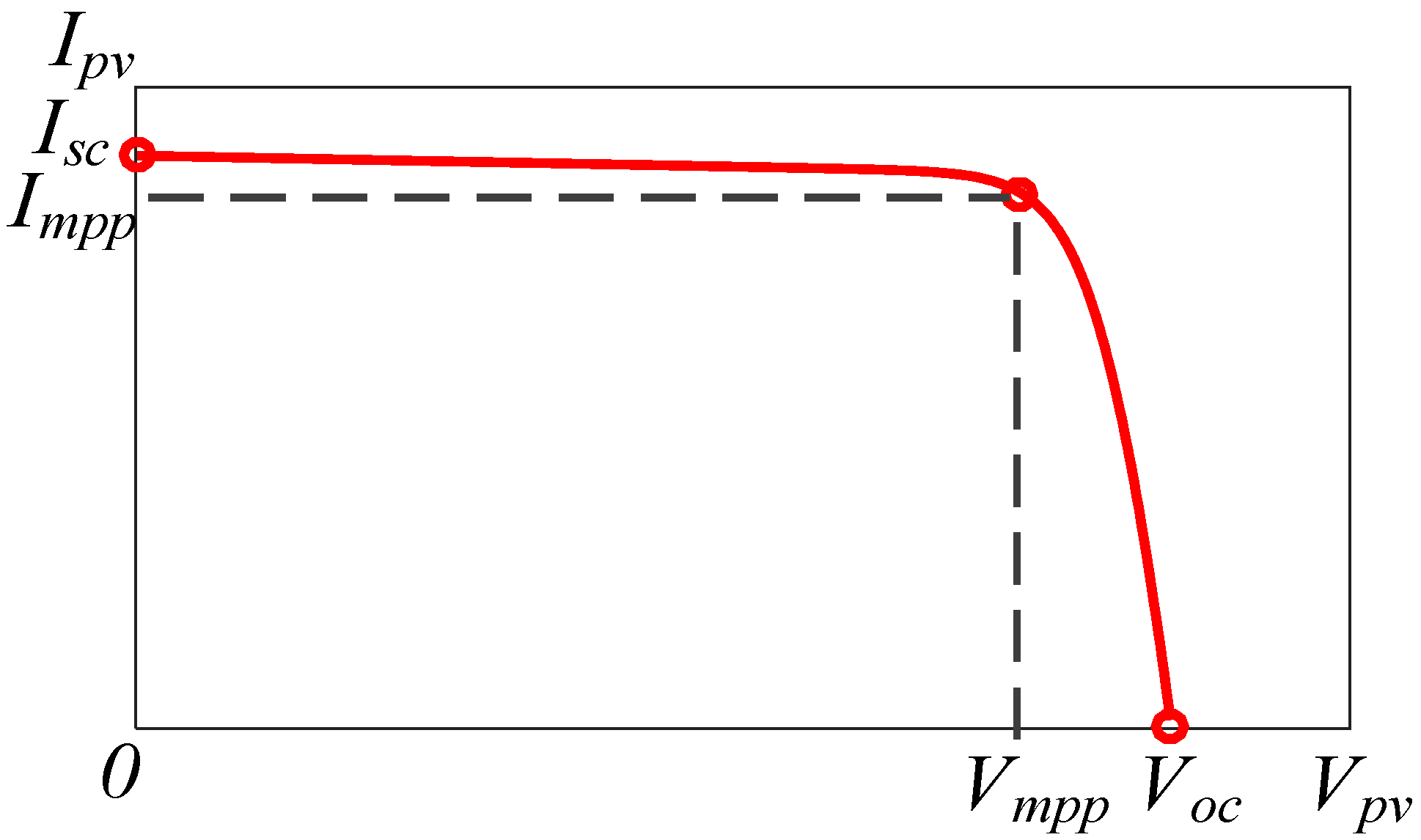
Eg is the forbidden band width of the semiconductor material; and
N is the junction constant, which is 1.5. The electrical characteristics of the PV cells are shown in
Figure 7.
According to the actual needs and electric parameters, the PV cells should be connected in series or in parallel. The output current of each PV cell can then be expressed as:
In Equation (8), where Np and Ns are the number of the PV cells’ strings and parallel connections, and Rse is the equivalent series resistance of the PV cells after series and parallel connection.
2.3. The Model of the Lithium Iron Phosphate Battery
Recently, battery technologies based on lithium compounds have reduced cost and improved performance in terms of increased energy density. We used a LiFePO
4 battery as the power battery for the system, a type widely used in automobiles. Ships are generally less sensitive to weight restrictions than cars are, so more energy can be stored in a ship, which has boosted interest in using purely electric cruise ships based on lithium batteries. According to [
32], models for the charge or discharge processes of ships can use the improved Shepherd equation, expressed in Equations (9) and (10), which disregards the influence of temperature on batteries. When batteries are in the discharge and charge processes, their voltage can be expressed thus:
where
Vbatt is the battery terminal voltage,
E0 is the nominal voltage,
K is the polarization constant,
Q is the battery capacity,
i* is the filter current,
A is the exponential voltage, and
B is the exponential time constant.
2.4. Working Principle and Model of Inverter Power
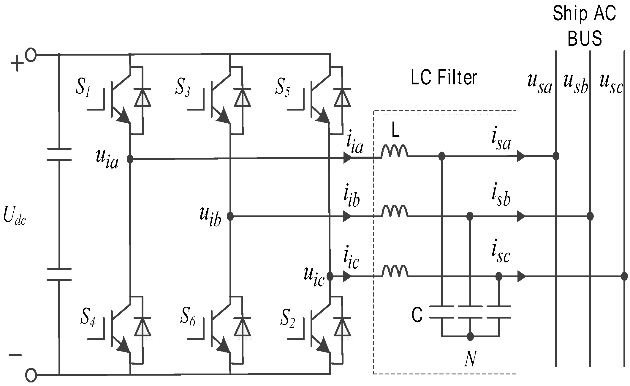
Considering that the ship’s distribution mode is mainly a three-phase, three-wire system, a relatively simple three-phase full bridge topology is applied for the main power circuit. This is shown in
Figure 8, where the LC filter is selected for the filter and
Udc is used as the DC voltage;
uia,
uib, and
uic act as the inverter output voltages;
iia,
iib, and
iic act as the inverter output currents;
usa,
usb, and
usc are the bus voltages;
isa,
isb, and
isc are the bus currents; L is the filtering inductance; and C is the filtering capacitance.
The inverter control strategy can be divided into three control modes: constant power control (PQ), constant voltage and frequency control (V/f), and dropping control. Depending on the requirements of different operation modes, different control algorithms can be selected to match each mode. The main purpose of this paper is to investigate the best operation mode for parallel inverters and then better utilize the solar energy of PV cells, so we adopted the PQ control method. The voltage/current values on the
dq axis can be obtained by PARK transformation, and according to instantaneous power theory, the active and reactive power outputs from the inverter can be expressed as:
Selecting the d axis and the voltage/current vector in the same direction, the following formula can be obtained:
According to Equation (12) and under the dp axis, the active power
P is determined by
usd and
isd, while the reactive power
Q is determined by
usd and
isq. The decoupling control of active power
Pref and reactive power
Qref is realized by controlling
isdref and
isqref, respectively, so that the voltage of the micro-grid system is unchanged. To control the current, the circuit equation of the inverter can be obtained from
Figure 9:
Using Equations (12) and (13) we can obtain the structural diagram of the PQ control, as shown in
Figure 9. From this figure the inner ring current references,
idref and
iqref, are obtained from the power references,
Pref and
Qref, to divide the voltage
usd in the outer ring. PI control is carried out using the difference between the currents references and the actual output currents
isd and
isq, and the modulated signals
udref and
uqref are obtained through feed-forward compensation and cross-coupling compensation.
2.5. The Simulation Model of the Ship’s Micro-Grid System
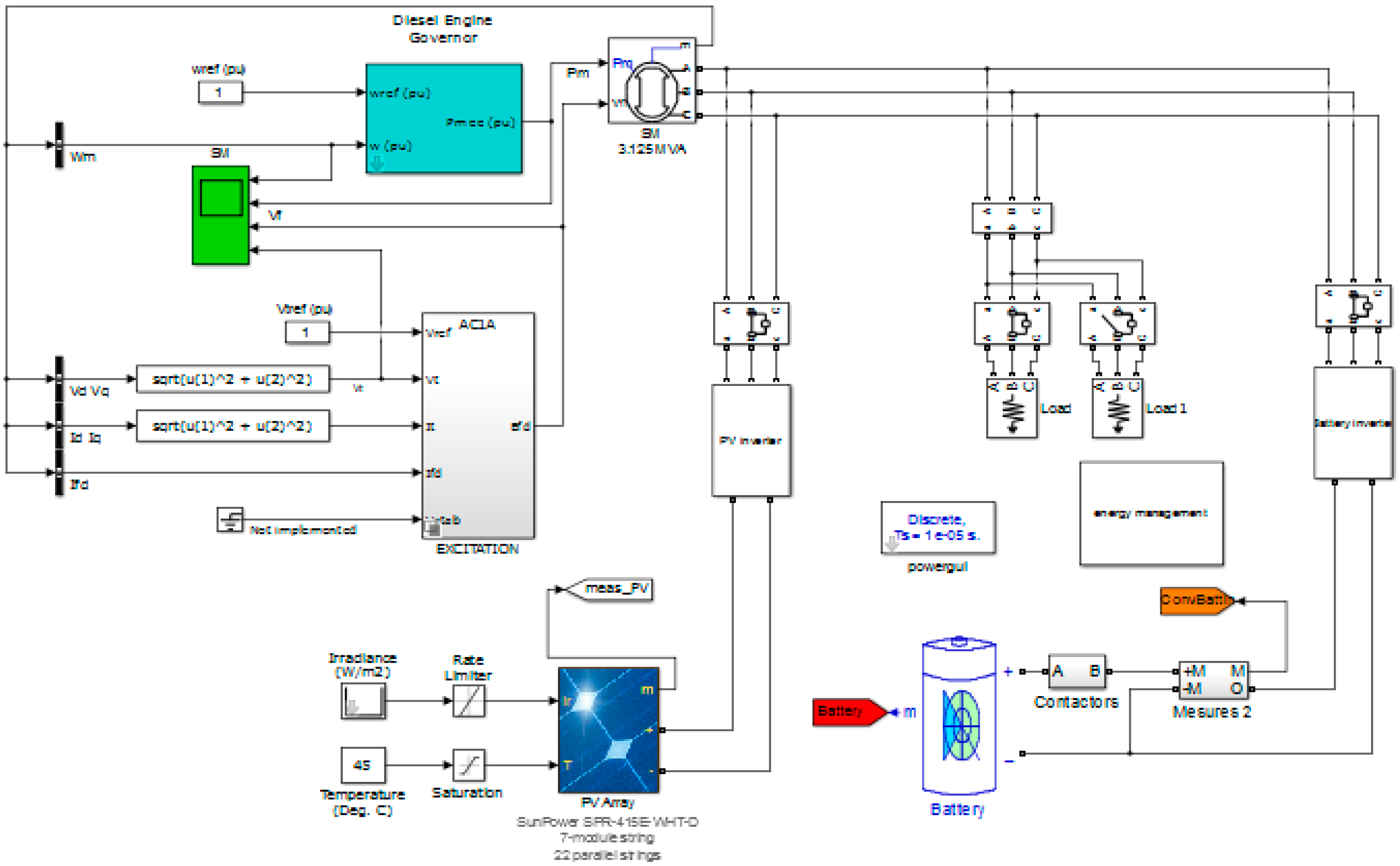
Combined with the proposed topological structure, the simulation model of the ship’s micro-grid system is established using the MATLAB Simscape component libraries and modules, as presented in
Figure 10.
3. Analysis of the Operation Characteristics in Parallel of the Ship’s Micro-Grid System
According to the design of ship’s micro-grid system, the system’s voltage and frequency were supported by the diesel generator, which provided the main power supply, and the sources from the inverter of solar PV cells and lithium batteries both were used according the following algorithm. Assuming that the solar power output was maximum and constant, the power distribution of the micro-grid system could be determined by controlling the power output of the lithium battery pack. Based on the characteristics of the marine electrical propulsion system, this article studies the micro-grid energy management strategy for the sudden change in load, which can improve the power quality (frequency) of the ship’s micro-grid under dynamic load. This strategy is based on the assumption that the output of PV power generation system remains constant, and we do not explore the complex dynamics of PV power generation system. Since this study is based on the output of different power generation units equal to the load power (conservation of energy), the PV output variation can also be considered as sudden load change, so the research conclusion can also be used for PV output variation. From this point, the proposed system can still control the actual PV channels (practical PV panels).
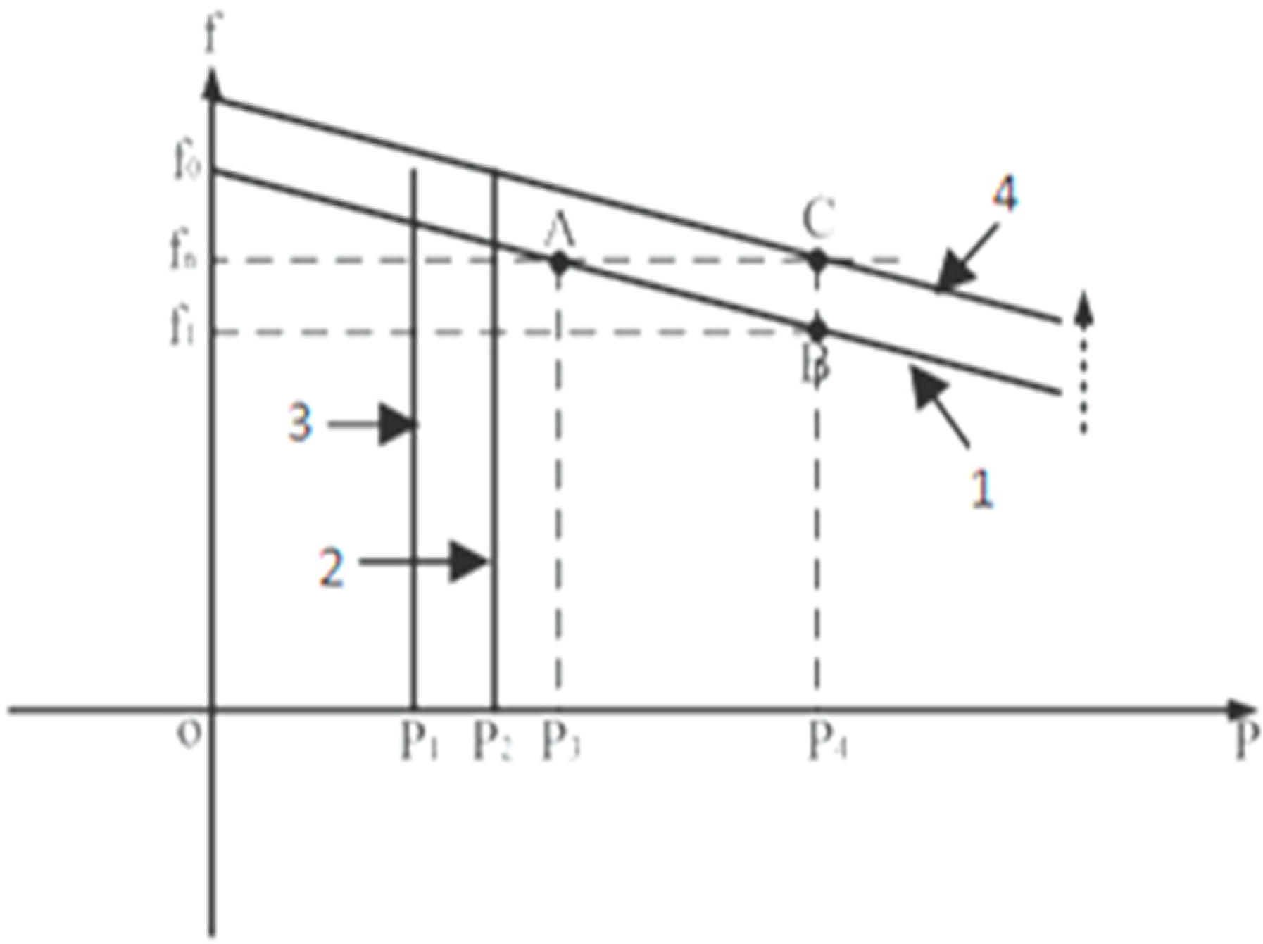
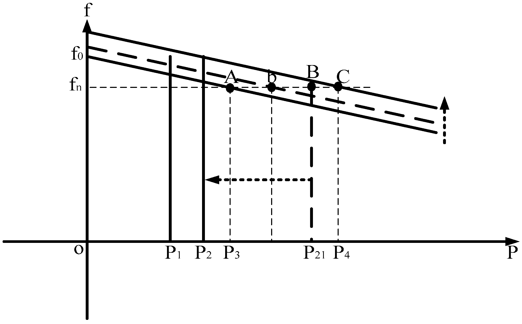
The governor characteristic (power-frequency characteristic curve) of the diesel generator is shown in curve 1 of
Figure 11 [
30]; this is also called the first adjustment rule between output power and power frequency. To stabilize the frequency around the ratings value, the throttle can be adjusted according to the output power, which shifts the characteristic curve up and down; this is called the second adjustment rule. The output frequency of the lithium battery inverter follows the frequency of the main power because the current-following algorithm is adopted. The output frequency is independent of the output power, which is determined by a given PQ value. The power-frequency characteristic of the lithium battery inverter is shown in curve 2 of
Figure 11 [
31]. The output frequency of the solar inverter is also followed by the main power frequency, and it is independent of the output power. The output power is determined by the maximum power point tracking (MPPT) algorithm, and the power-frequency characteristic of the solar inverter is shown in curve 3 of
Figure 11. The effect of load change on frequency fluctuation in the ship’s micro-grid system can be analyzed as follows.
Assuming that the ship’s micro-grid system is in stable operation at A point (rated frequency
fn) under the certain working conditions in
Figure 11, the solar output power is
P1, the output power of the lithium battery pack is
P2, and the output power of the diesel generator is
P3. Load increase
ΔP = P4 − P3 always happens suddenly. When we use the PQ algorithm for inverter operation,
ΔP will be borne by the diesel generators only because the power outputs of the solar PV and batteries are constant values. From
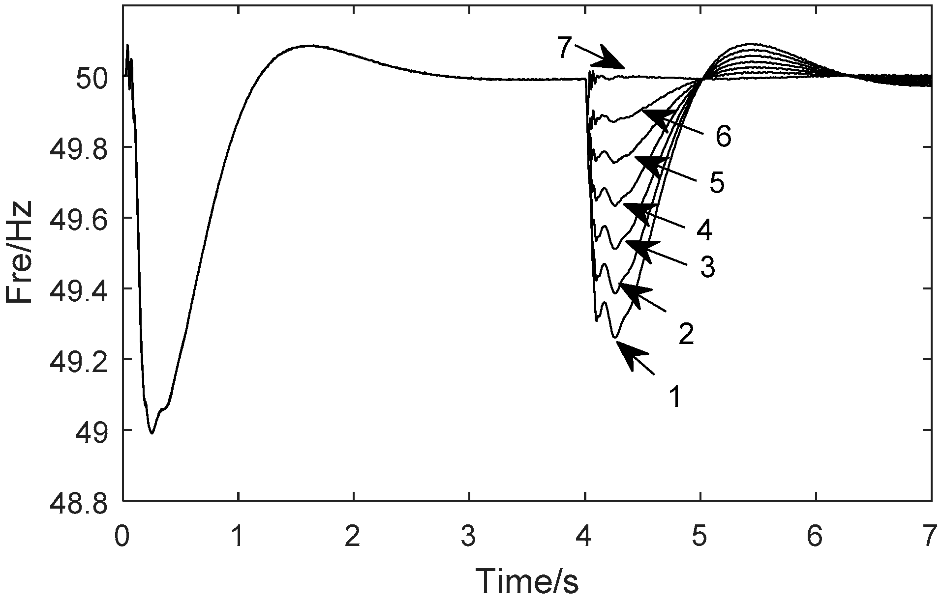
Figure 11, we can describe the regulation process for static system frequency. At first, the power frequency will adjust according to curve 1 and the system operation point from A to B. Then, the diesel throttle will be controlled to change the system’s operation point from B to C (curve 4). For better operation, we postulate the initial conditions in which the system load is 80 kW, the power output of the PV array controlled by the MPPT algorithm is 15 kW, the power output of the energy storage battery is 20 kW, the remaining 45 kW of power is borne by the diesel generators, and the system reaches stable operation status2 s after the simulation start. When t = 4 s, the load increases from 0 to 30 kW with a step increase of 5 kW. The simulation results of the system’s corresponding dynamic frequency response are shown in curve 7 to curve 1 of
Figure 12.
The above analysis of system static output shows that when the load power increases, the system’s frequency drops from fn to f1. If the system is not controlled, the frequency fluctuation will inevitably affect the system’s power quality. Especially during dynamic system processes, when the mutation load increases, the harmonic increase in inverter power output is largely due to the frequency fluctuation overshoot. That condition not only will reduce the power grid’s power quality but also will make the grid collapse in a serious situation (such as the propeller touching bottom).
5. Analysis of Simulation and Results
Based on the overall model of the ship’s micro-grid system developed by MATLAB/SIMULINK, we ran a simulation to evaluate the effectiveness of the power distribution and control allocation strategy and the system’s operational stability. The input parameters of the simulation were as follows:
- (1)
The specified outputs of the diesel generator were 100 kW, 380 V, and 50 Hz.
- (2)
The maximum power output of the PV was 15 kW.
- (3)
The rated capacity of the battery was 200 Ah, 537 V.
- (4)
Resistors were used to simulate the system load.
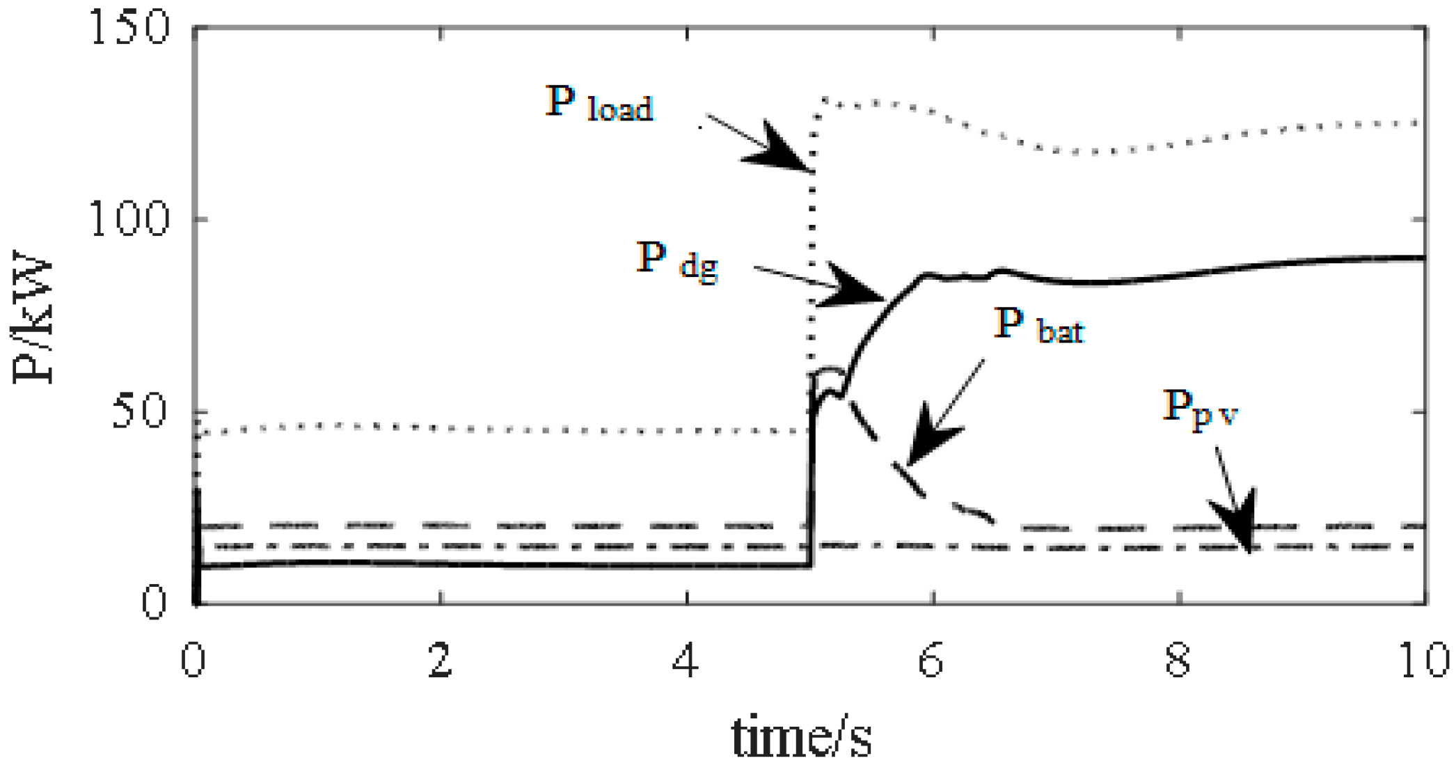
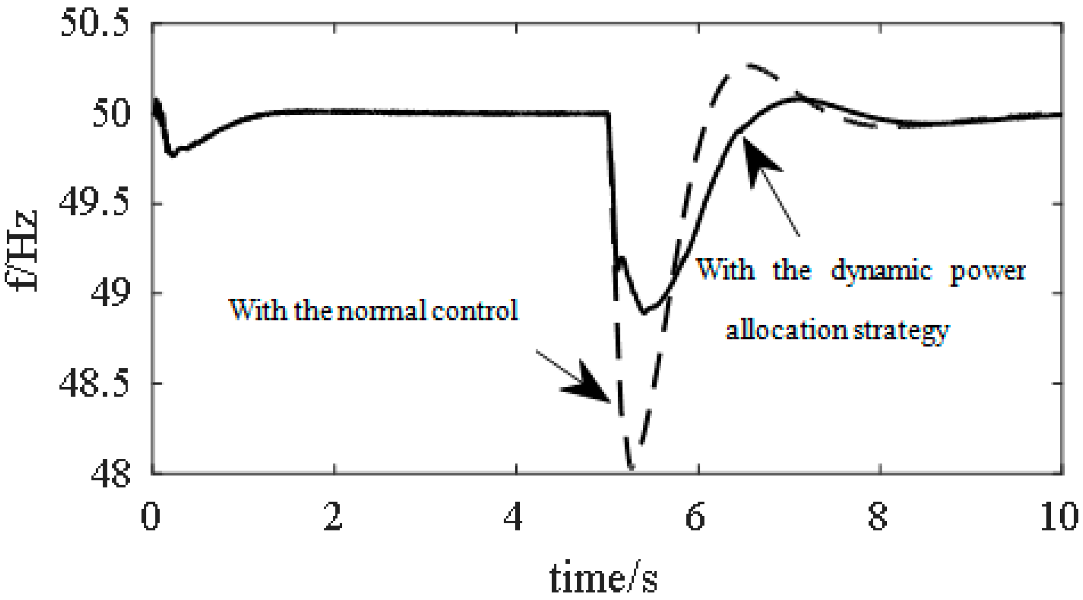
The initial conditions were that the system was operated in parallel on stable status: initial total load 45 kW, PV output 15 kW, diesel generator output 10 kW, and battery output 20 kW. At five seconds, the load was suddenly increased to 80 kW. The frequency response curve of the micro-grid system is shown in
Figure 19, and the operational profiles of the different energy modules are shown in
Figure 20.
The dotted line in
Figure 20 shows that the maximum frequency deviation was 2 Hz when the load was suddenly increased to 80 kW. The real line indicates the frequency response curve of the micro-grid system with the dynamic power allocation strategy. From the real line, the maximum frequency deviation was 1 Hz when the load variation suddenly increased to 80 kW. Compared with the two curves, the system frequency fluctuation was decreased by [(2 − 1)/2] × 100% = 50%using the proposed control strategy, proving it could efficiently improve the system’s dynamic performance.
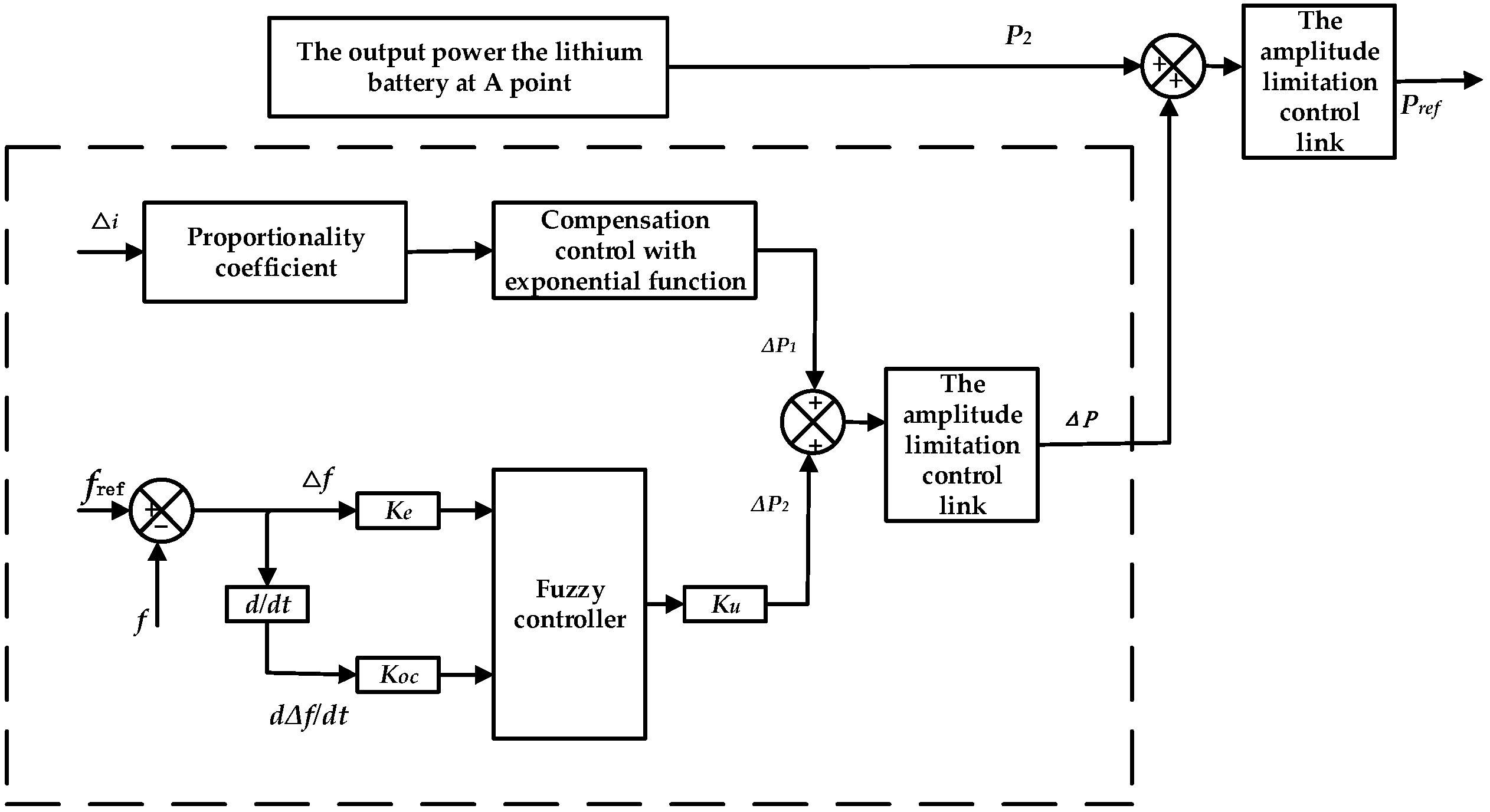
As can be seen from the load and power simulations for each power generation unit, presented in
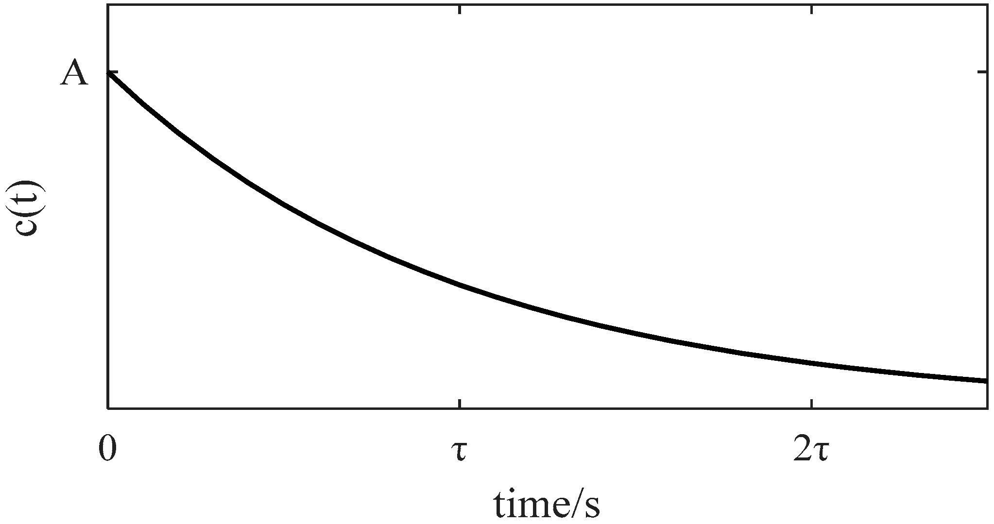
Figure 20, at the load mutation moment, the dynamic power reference value of the battery system quickly increased and the power diesel generator was minimized in the working state. At the same time, the dynamic power reference of the battery system decreased and the output power of the diesel generators increased. Finally, the dynamic power reference value of the battery system decreased to zero and all of the increased loads were borne by the diesel generators. Because the output power of the battery system decreased gradually according to the design of the
e exponential function, the diesel generators had enough response time for speed regulation, so they did not produce larger frequency fluctuations in the micro-grid system. The whole process of the power distribution system enabled full use of the lithium battery’s good instantaneous discharge performance, improved the power quality in the dynamic process of the micro-grid system, and efficiently ensured the system’s stability.
The combination of new energy technology and electrical propulsion technology is an effective way to solve the problems of energy saving and greenhouse gas emission reduction of ships. But as a relatively independent unit and regardless of actual structures or grid characteristics, the power grids of ships have the typical characteristics different from the ones of terrestrial regions. Investigation of the coordinated control strategy for different power generation units under different situations is the essential scientific problem that must be developed to ensure the stable economic operation of the ship’s micro-grid. This paper investigated a useful strategy to improve the utilization rate of renewable energy under static conditions, reduce the frequency fluctuation of the system under dynamic conditions, and improve the power quality and system stability of the ship’s micro-grid.
In the past, Guo et al. had combined the battery with SC as the energy storage system and they investigated the control strategy of the power balance and the optimal energy management in MVDC power system [
37]. The system could be used to maintain the MVDC bus voltage within desired margin, which was usually 10% around the nominal MVDC voltage. The objective of this research was to investigate the battery as the main power supply of cruise ships and investigate the control strategy of the power quality (constant frequency), which could have the optimal energy management in LVAC power system. For the widely used alternating current (AC) electrical propulsion ships, if the above micro-grid system architecture is adopted, a large number of power converters need to be connected to the direct current (DC) grid side to realize the conversion of the electrical energy form. Then the electrical energy utilization rate is low and the cost is high, although the voyage of large ships can be far away, the application prospect is not good. Therefore, the investigated management and distribution strategies are used, the ship’s AC grid composed of the generator and the new energy is more advantageous, practical, and popularized.
6. Conclusions
The combination of new energy technology and electrical propulsion technology is an effective way to solve energy saving and greenhouse gas emission reduction of ships. But as a relatively independent unit, regardless of the actual structures or grid characteristics, ships have typical characteristics different from terrestrial power grids. The coordinated control strategy of different power generation units under different situations is the essential scientific problem that must be solved to ensure the stable economic operation of the ship’s micro-grid. This paper investigated a strategy for the ship’s micro-grid, which consisted of PV, DG, and a lithium battery. For that, the characteristics of the grid-connected operation of the new energy inverter power system, the ship’s power station, and the corresponding dynamic power allocation strategy were proposed. In this study, we successfully constructed a simulation model to integrate the characteristics of a photovoltaic cell, a diesel generator, and a lithium battery (PV/DG/BAT), then investigated using a ship’s micro-grid system to combine the three power sources. The constructed model allowed us to explore frequency fluctuations in the multi-energy micro-grid system under dynamic conditions. The dynamic power reference value was easily obtained by fuzzy control and a current compensation algorithm. Via the proposed distribution strategy for dynamic power, under the same conditions the diesel generator had enough response time to regulate its rotating speed, and the output powers had reasonable distribution. When the load was suddenly changed, the proposed strategies reduced the frequency fluctuation by 50%. The proposed strategies could also be used to reduce the frequency fluctuation caused by sudden changes because of the intermittent characteristics of PV power, greatly improving the stability of PV/DG/BAT-based dynamic power.


