Article

Assessment of a Universal Reconfiguration-less Control Approach in Open-Phase Fault Operation for Multiphase Drives

1
Electronic Engineering Department, University of Seville, 41092 Sevilla, Spain
2
Electrical and Thermal Engineering Department, University of Huelva, 21007 Huelva, Spain
3
Electrical Engineering Department, University of Málaga, 29071 Málaga, Spain
*
Author to whom correspondence should be addressed.
Energies 2019, 12(24), 4698; https://doi.org/10.3390/en12244698
Submission received: 7 November 2019 / Revised: 2 December 2019 / Accepted: 5 December 2019 / Published: 10 December 2019
(This article belongs to the Special Issue Control of Multiphase Machines and Drives)

Abstract

:
Multiphase drives have been important in particular industry applications where reliability is a desired goal. The main reason for this is their inherent fault tolerance. Different nonlinear controllers that do not include modulation stages, like direct torque control (DTC) or model-based predictive control (MPC), have been used in recent times to govern these complex systems, including mandatory control reconfiguration to guarantee the fault tolerance characteristic. A new reconfiguration-less approach based on virtual voltage vectors (VVs) was recently proposed for MPC, providing a natural healthy and faulty closed-loop regulation of a particular asymmetrical six-phase drive. This work validates the interest in the reconfiguration-less approach for direct controllers and multiphase drives.

1. Introduction

The use of variable-speed drives has grown in the last few decades because of microprocessor and power converter development, with an expectation that 80% of all the produced energy will be used in locomotive traction, electric ship propulsion, more-electric aircraft and renewable energy applications. Although three-phase machines are the common trend, the interest of the research community has recently focused on machines with more than three phases, named multiphase machines, due to their advantages in terms of reliability and postfault usage [1]. This is the case of safety applications, where the fault-tolerant ability of multiphase drives has attracted the interest of the scientific community. Having more than three phases allows the faulty operation of the drive under specific voltage, current and/or power limits, which makes multiphase drives an interesting solution in critical industry applications, i.e., offshore wind generators, more-electric aircraft and field or traction applications, e.g., the Royal Navy Type-45 destroyer [2]. Thus, multiphase drives can still be operated without the need for heavy topological changes in the power converter, even if a phase is missing, provided that the number of remaining phases is equal to or greater than three [3,4,5].
Most of the recent multiphase drive research has been focused on the extension of the control methods usually applied in conventional three-phase drives, along with their enhancement to provide the best performance of the system [6,7]. Compared to classical three-phase drives, multiphase ones reduce the electrical stress in drives and power electronic components, since they can manage more power with lower torque pulsation and current harmonic contents [8]. In this context, the most common control strategy is the field-oriented control (FOC) technique, based on linear cascaded control loops and assisted by coordinate transformations and modulation stages. The multiphase machine is decomposed into multiple orthogonal dq subspaces (fundamental and harmonics components), with each set of dq variables being independently controlled. The reference voltages are determined by proportional–integral (PI) controllers, which are inputs for the modulation stage to generate pulse-width-modulation (PWM) switching signals to a power converter, usually a voltage-source converter (VSC). Alternatives to this technique are the ‘direct control’ methods, including direct torque and model-based predictive controllers (DTC and MPC, respectively). They directly switch the VSC state, avoiding the PWM stage and forcing the controlled variables to rapidly track the reference, while achieving normal operation of the drive [1,2,5,8].
Since the healthy operation of the multiphase drive is a significant and complex issue, important and recent research papers also analyze the implications of faulty operation from the control perspective, where FOC, DTC and MPC methods have been studied. It is interesting to note that control techniques based on ‘nonlinear’ controllers (DTC and MPC methods or ‘direct’ controllers) appear as promising control alternatives due to their flexibility and simple formulation, competing with FOC techniques for leading the control solution in the field of multiphase machines and drives [5,8]. The term ‘fault tolerance’ has broad application since the fault can occur in many elements of the system, including VSC and machine faults that lead to short-circuit (i.e., phase [9], VSC switch [10], interturn [11]) or open-circuit (i.e., phase [12], VSC switch [13], or line [14]) faults. This work analyzes the field of multiphase drives and their use in open-phase fault operations, where the recent definition of a reconfiguration-less MPC controller for asymmetrical six-phase drives, based on virtual voltage vectors (VVs) and useful in healthy and faulty operation, seems to be an interesting advance for using direct controllers [15,16]. This work goes beyond [15,16], extending and experimentally validating the idea to different direct controllers and multiphase drives.

2. Basis of Natural Fault-Tolerant Controllers Using MPC

The research activity in the application of MPC techniques in the field of multiphase drives has recently given rise to numerous control approaches, the most popular being the finite control set MPC (FCS-MPC) method due to the limited number of possible switching states of the power converter. The most common use is the result of its combination with FOC methods, with the outer speed control loop being maintained while the inner current regulators are substituted by FCS-MPC controllers. This control scheme is depicted in Figure 1, where a distributed-winding five-phase Induction Motor (IM) drive is used as a case example.
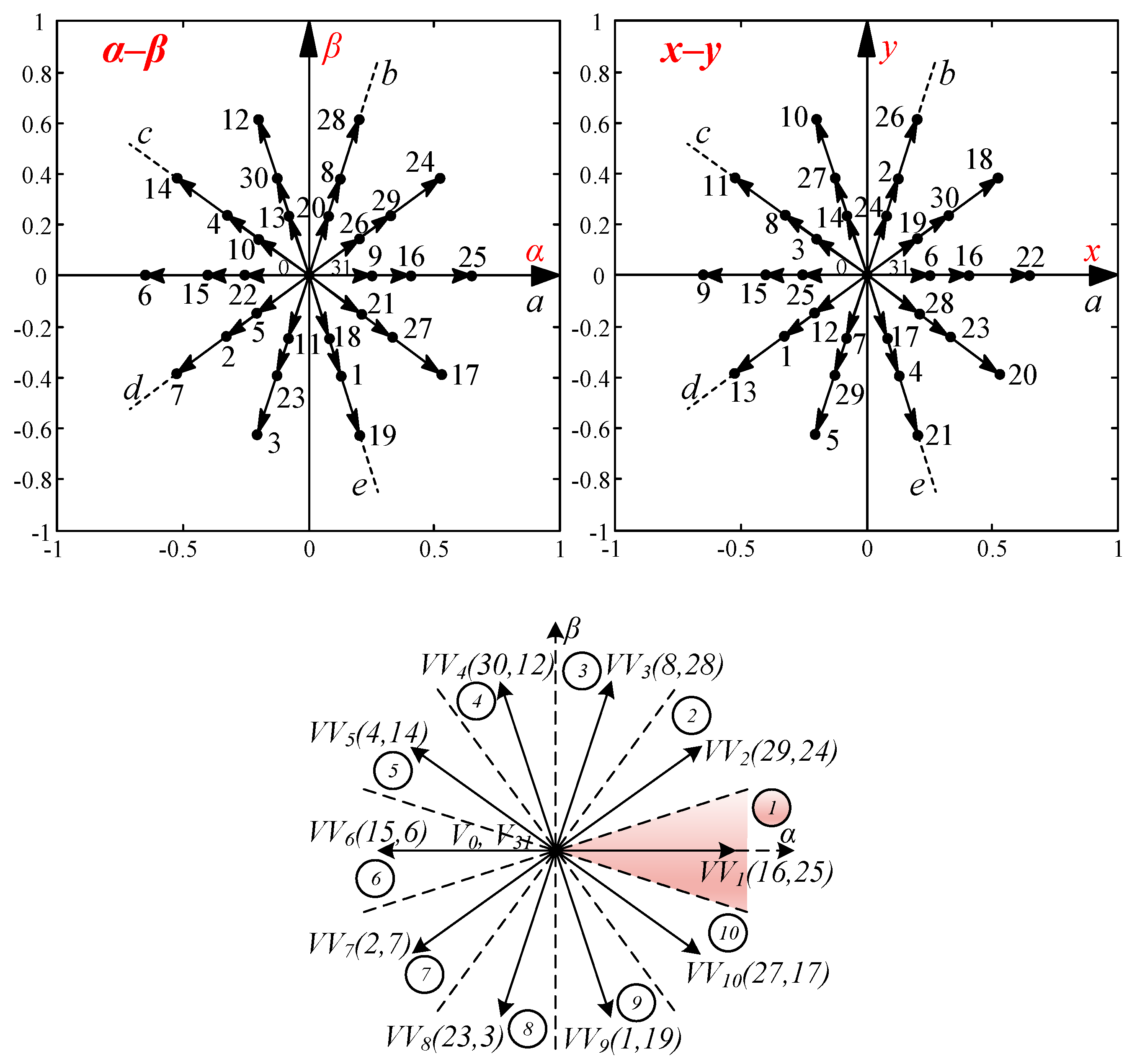
The fault-tolerant capability of multiphase drives was first studied in [17], where it was shown that n-phase machines can operate after one or several fault occurrences, as long as the number of healthy phases remains greater than or equal to three and at the expense of a reduction in the torque production. The FCS-MPC control system technology finds itself currently at a paradigm-changing tipping point, where emerging applications are under development. In this context, FCS-MPC has proven to be a promising alternative in the fault-tolerance control of the drive, where it was recently shown [16] that it is possible to skip any control reconfiguration if virtual voltage vectors (VVs) are used. The main idea, shown in Figure 2 for our case example, is to substitute the available voltage vectors with new virtual voltage vectors. Large and medium voltage vectors, which are aligned in the αβ plane with opposite directions in the xy plane, are combined to provide zero average voltage in the xy subspace, so harmonic currents in the xy subspace are reduced. This has been termed natural fault-tolerance capability, and it has been verified so far by using FCS-MPC strategies and six-phase drives [16], where the use of VVs introduces an open-loop control of the stator current in the xy plane, avoiding the main problems of full-order closed-loop controllers when the open-phase fault occurs and the current cannot flow through a damaged phase, e.g., searching for incompatible control goals and voltage vectors that are no longer available.

3. Extension of the Reconfiguration-less Approach to the DTC Case

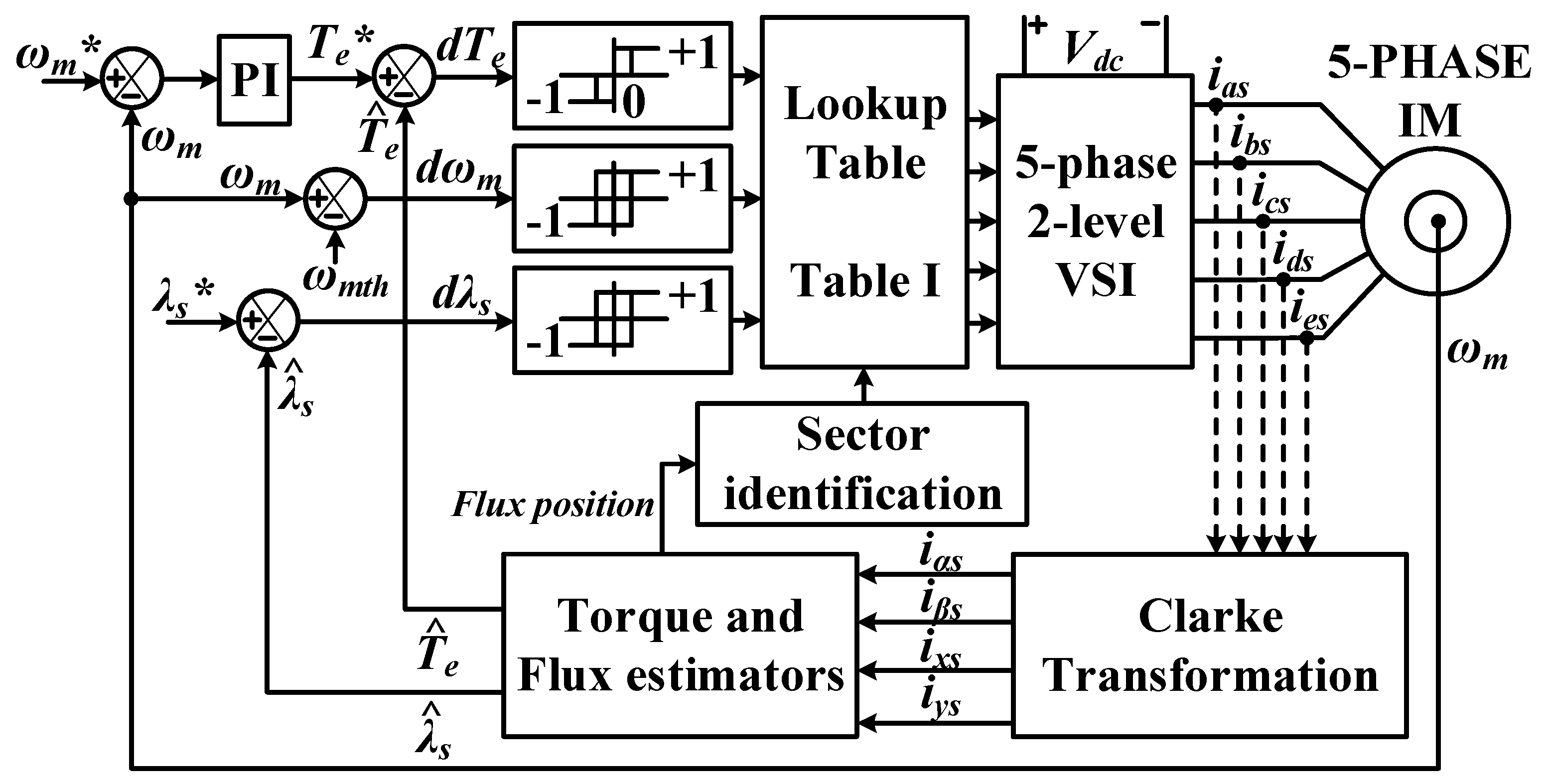
DTC-based controllers have been also recently proposed and studied in the multiphase drive field for healthy and faulty modes of operation (Figure 3) [18,19,20,21]. The basis is to select a stator voltage vector, according to Table 1 and the VV concept, using hysteresis-based controllers for every control period, to obtain reference torque and stator flux tracking. For such purpose, the model of the machine is used to estimate the stator flux and the electromagnetic torque for the DTC controller [22]. In fact, the VVs concept was originally introduced as a way to extend DTC to the multiphase field, maximizing the torque production while minimizing harmonic components in the xy plane. Hence, the use of VVs in DTC also avoids the problems with full-order closed-loop controllers when open-phase faults occur. This work demonstrates that DTC strategies using VVs can also provide the natural fault-tolerant capability, allowing a ripple-free postfault operation with no reconfiguration of the control strategy. Then, opposite to [21], lookup tables (see Table 1) are not reconstructed after a fault occurrence, and the same control scheme and VVs are used in the pre- and postfault situations.

4. Experimental Work

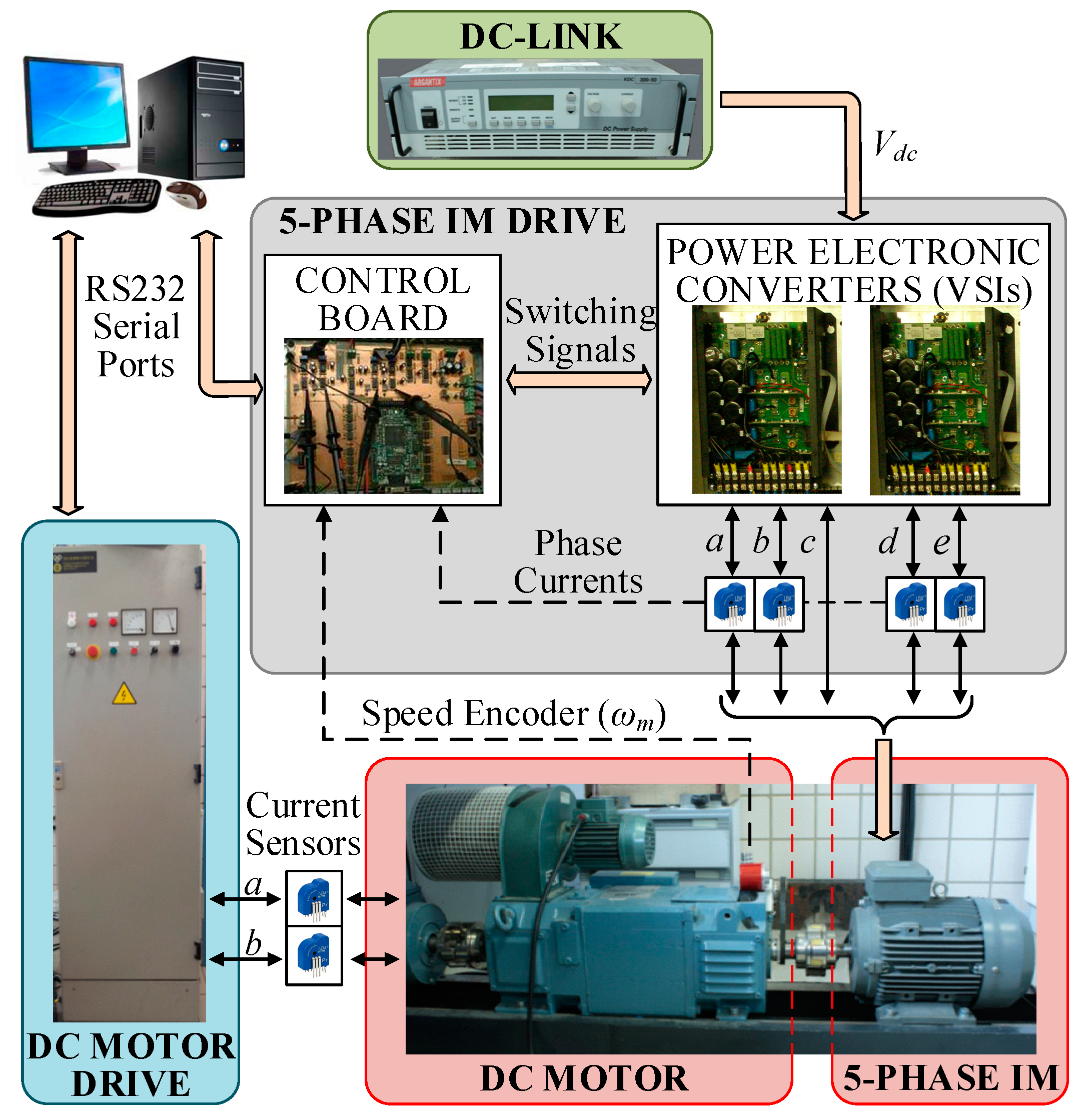
The performance of the DTC controller using VVs was experimentally tested in healthy and open-phase operation, with no reconfiguration of the controller. The experimental test bench is shown in Figure 4. It was composed of a five-phase IM fed by two conventional three-phase VSCs from Semikron. The DC-link was set to 300 V by an external DC power supply. The controller was programmed on a MSK28335 board and a TMS320F28335 microcontroller. The mechanical speed was measured by a digital encoder and the microcontroller’s peripherals. Additionally, a variable load torque was applied by a mechanically coupled DC machine. An open-phase fault condition in phase ‘a’ was emulated in the provided tests by opening a power relay connected in series with the phase. The IM characteristics are listed in Table 2; the reference stator flux was set to 0.389 Wb, the sampling time used was 100 µs and the hysteresis bands of the torque and flux regulators were fixed at 1.06% and 1.29% of the rated values, respectively. Note that a limitation in the integral part of the controller and an anti-windup scheme were included in the implemented control algorithm to prevent integration windup in the PI-based speed controller when the actuator is saturated.
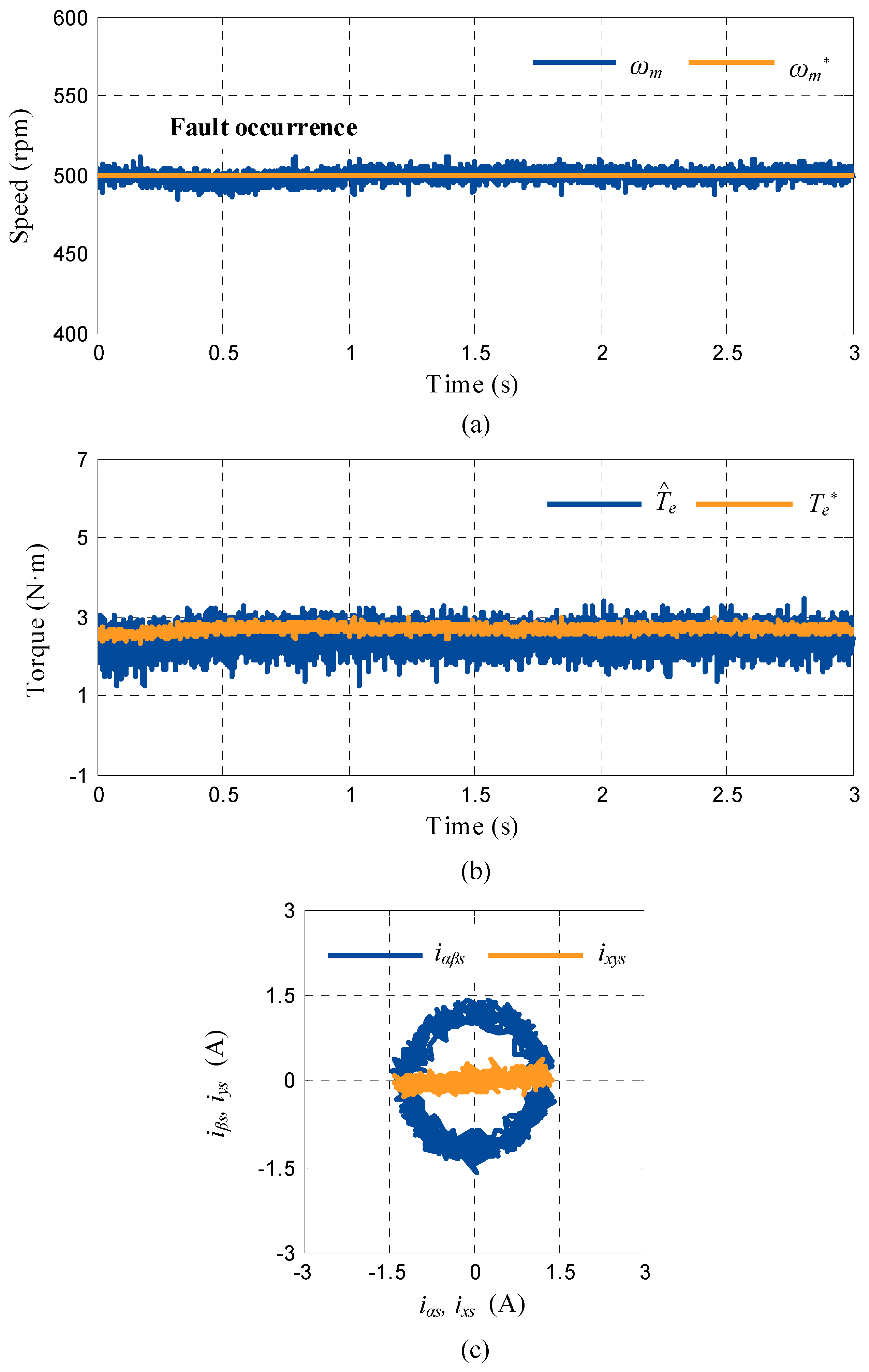
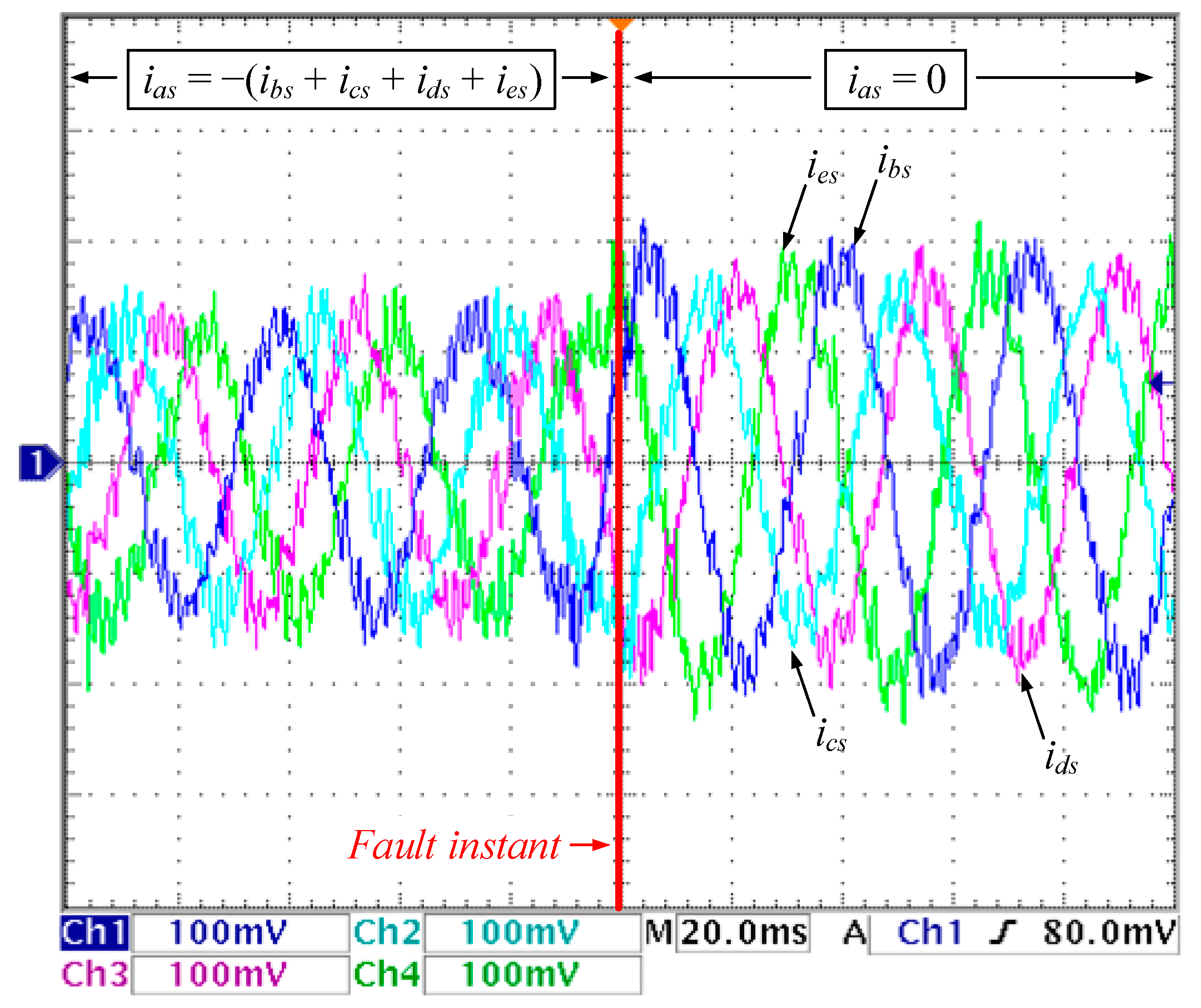
The transition from prefault to postfault operation was first analyzed when the speed was maintained at 500 rpm and a load torque around 60% of the nominal one was imposed. The results obtained are shown in Figure 5 and Figure 6. Although the speed decreases a little when the fault occurs, it can be observed that the DTC controller is capable of controlling the speed and the torque of the system even using the prefault voltage vectors and system model (see Figure 5a,b). Since the MMF remains the same in both healthy and faulty operation, a circular trajectory is obtained in the α–β currents, as can be seen in Figure 5c. However, a horizontal line appears in the xy plane because ixs = −iαs and iys = 0. In accordance with the well-known minimum copper loss criterion [23], stator phase currents ‘b’ and ‘e’ are equal in magnitude but present unequal peak values compared to ‘c’ and ‘d’ phase currents, as shown in Figure 6.
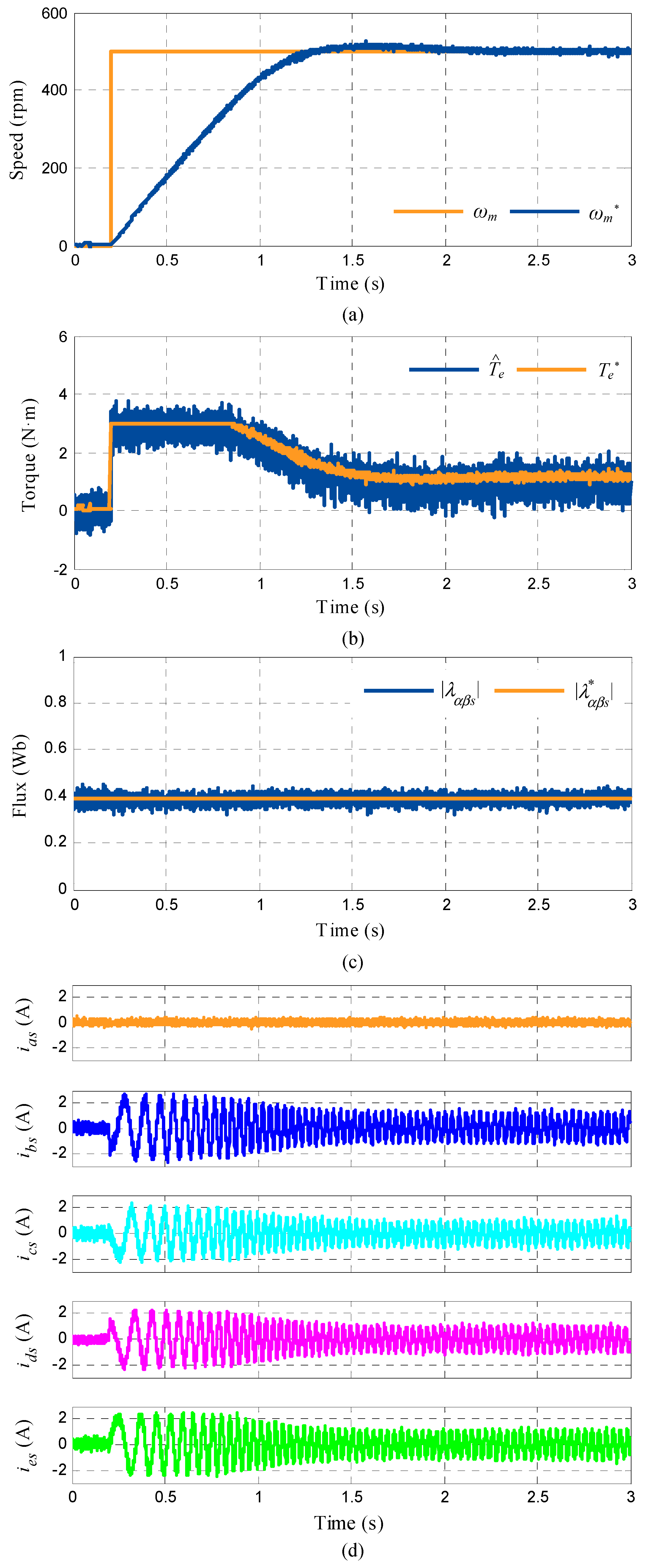
Next, the dynamic performance of the DTC controller in faulty operation was analyzed. A speed step from 0 to 500 rpm was forced with a null-load torque condition. Figure 7 shows the speed, torque and flux performance (Figure 7a–c), and it can be seen that the DTC scheme provides an accurate tracking performance of all variables. It is necessary to highlight that the electrical torque is limited to 3 N·m, since nominal torque is not reachable in a postfault situation. The phase current evolution is also depicted in Figure 7d.
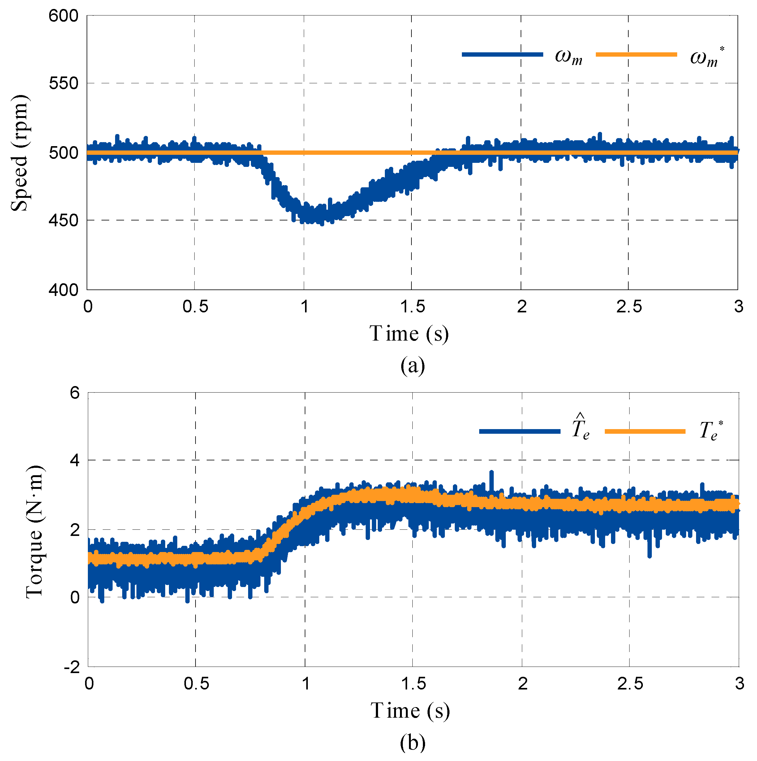
The rejection properties of the system are also studied and the results presented in Figure 8. A change in the load torque is applied at t = 0.8 s while the speed reference is fixed to 500 rpm. The tracking performance of the electrical torque is quite accurate, even in the transitory. On the other hand, a decrease in the rotor speed is observed when the fault occurs, but the controller successfully manages the disturbance in a short period of time.
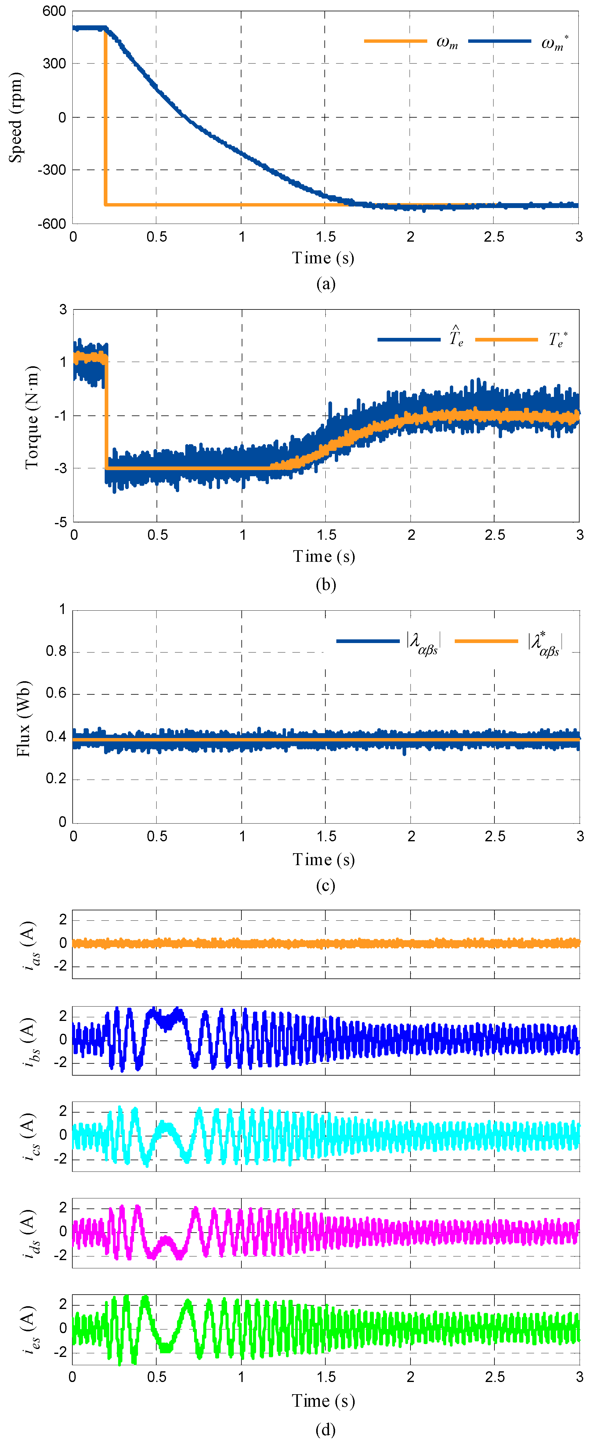
Finally, a reversal test is reproduced and shown in Figure 9. In this experiment, the reference speed is first settled in at 500 rpm and then changed to −500 rpm at t = 0.2 s. The system is again operated in open-phase fault condition, with a null load torque applied to the system. An appropriate tracking of the speed, the estimated torque and the stator flux is obtained, with a good crossing by zero performance. The evolution of phase currents during this test is depicted in Figure 9d.

5. Conclusions

The recent interest in multiphase drives for particular industry applications is mainly based on their inherent fault-tolerant characteristics. However, the complexity of the applied controllers, which usually require extensive reconfiguration to manage the faulty operation, hinders this interest. This work shows that VVs combined with direct controllers can overcome this difficulty and provide a natural fault-tolerant capability for multiphase drives. Indeed, the idea, previously introduced for FCS-MPC controllers, is here experimentally validated when DTC is applied, where VVs allow the use of the same voltage vectors, lookup tables and control scheme in pre- and postfault situations.

Author Contributions

Conceptualization and methodology, F.B. and M.J.D.; software, M.B., P.S. and I.G.-P.; validation, all authors; formal analysis and investigation, all authors; resources, all authors; data curation, all authors; writing—original draft preparation, F.B.; writing—review and editing, all authors; visualization, all authors; supervision, M.J.D. and F.B.; project administration, F.B.; funding acquisition, I.G.-P. and F.B.

Funding

This research was funded by the Spanish Government.

Conflicts of Interest

The authors declare no conflict of interest.

References

  1. Levi, E.; Barrero, F.; Duran, M.J. Multiphase Machines and Drives-Revisited. IEEE Trans. Ind. Electron. 2016, 63, 429–432. [Google Scholar] [CrossRef] [Green Version]
  2. Duran, M.J.; Levi, E.; Barrero, F. Multiphase Electric Drives: Introduction. In Wiley Encyclopedia of Electrical and Electronics Engineering; John Wiley & Sons: Hoboken, NJ, USA, 2017. [Google Scholar]
  3. Mohammadpour, A.; Parsa, L. A Unified Fault-Tolerant Current Control Approach for Five-Phase PM Motors with Trapezoidal Back EMF under Different Stator Winding Connections. IEEE Trans. Power Electron. 2013, 28, 3517–3527. [Google Scholar] [CrossRef]
  4. Mohammadpour, A.; Sadeghi, S.; Parsa, L. A Generalized Fault-Tolerant Control Strategy for Five-Phase PM Motor Drives Considering Star, Pentagon, and Pentacle Connections of Stator Windings. IEEE Trans. Ind. Electron. 2014, 61, 63–75. [Google Scholar] [CrossRef]
  5. Duran, M.J.; Barrero, F. Recent Advances in the Design, Modeling and Control of Multiphase Machines-Part 2. IEEE Trans. Ind. Electron. 2016, 63, 459–468. [Google Scholar] [CrossRef]
  6. Sadeghi, S.; Guo, L.; Toliyat, H.A.; Parsa, L. Wide Operational Speed Range of Five-Phase Permanent Magnet Machines by Using Different Stator Winding Configurations. IEEE Trans. Ind. Electron. 2012, 59, 2621–2631. [Google Scholar] [CrossRef]
  7. Mercorelli, P.; Kubasiak, N.; Liu, S. Multilevel Bridge Governor by using Model Predictive Control in Wavelet Packets for Tracking Trajectories. In Proceedings of the IEEE International Conference on Robotics and Automation, New Orleans, LA, USA, 26 April–1 May 2004; Volume 4, pp. 4079–4084. [Google Scholar]
  8. Barrero, F.; Duran, M.J. Recent Advances in the Design, Modeling and Control of Multiphase Machines-Part 1. IEEE Trans. Ind. Electron. 2016, 63, 449–458. [Google Scholar] [CrossRef]
  9. Barcaro, M.; Bianchi, N.; Magnussen, F. Faulty Operations of a PM Fractional-Slot Machine with a Dual Three-Phase Winding. IEEE Trans. Ind. Electron. 2011, 58, 3825–3832. [Google Scholar] [CrossRef]
  10. Nguyen, N.K.; Meinguet, F.; Semail, E.; Kestelyn, X. Fault-Tolerant Operation of an Open-End Winding Five-Phase PMSM Drive with Short-Circuit Inverter Fault. IEEE Trans. Ind. Electron. 2016, 63, 595–605. [Google Scholar] [CrossRef] [Green Version]
  11. Zarri, L.; Mengoni, M.; Gritli, Y.; Tani, A.; Filippetti, F.; Serra, G.; Casadei, D. Detection and Localization of Stator Resistance Dissymmetry Based on Multiple Reference Frame Controllers in Multiphase Induction Motor Drives. IEEE Trans. Ind. Electron. 2013, 60, 3506–3518. [Google Scholar] [CrossRef]
  12. Abdel-Khalik, A.S.; Masoud, M.I.; Ahmed, S.; Massoud, A. Calculation of Derating Factors based on Steady-State Unbalanced Multiphase Induction Machine Model under Open Phase(s) and Optimal Winding Currents. Electr. Power Syst. Res. 2014, 106, 214–225. [Google Scholar] [CrossRef]
  13. Guzman, H.; Barrero, F.; Duran, M.J. IGBT-Gating Failure Effect on a Fault-Tolerant Predictive Current-Controlled Five-Phase Induction Motor Drive. IEEE Trans. Ind. Electron. 2015, 62, 15–20. [Google Scholar] [CrossRef] [Green Version]
  14. Dwari, S.; Parsa, L. An Optimal Control Technique for Multiphase PM Machines under Open-Circuit Faults. IEEE Trans. Ind. Electron. 2008, 55, 1988–1995. [Google Scholar] [CrossRef]
  15. Gonzalez-Prieto, I.; Duran, M.J.; Aciego, J.J.; Martin, C.; Barrero, F. Model Predictive Control of Six-Phase Induction Motor Drives using Virtual Voltage Vectors. IEEE Trans. Ind. Electron. 2018, 65, 27–37. [Google Scholar] [CrossRef]
  16. Gonzalez-Prieto, I.; Duran, M.J.; Bermúdez, M.; Barrero, F.; Martín, C. Assessment of Virtual-Voltage-based Model Predictive Controllers in Six-phase Drives under Open-Phase Faults. IEEE J. Emerg. Sel. Top. Power Electron. 2019, 1. [Google Scholar] [CrossRef]
  17. Jahns, T.M. Improved Reliability in Solid-State AC Drives by means of Multiple Independent Phase Drive Units. IEEE Trans. Ind. Appl. 1980, 16, 321–331. [Google Scholar] [CrossRef]
  18. Yousefi-Talouki, A.; Gholamian, S.A.; Yousefi-Talouki, M.; Ilka, R.; Radan, A. Harmonic Elimination in Switching Table-based Direct Torque Control of Five-Phase PMSM using Matrix Converter. IEEE Symp. Humanit. Sci. Eng. Res. Kuala Lumpur 2012, 777–782. [Google Scholar]
  19. Zheng, L.; Fletcher, J.E.; Williams, B.W.; He, X. A Novel Direct Torque Control Scheme for a Sensorless Five-Phase Induction Motor Drive. IEEE Trans. Ind. Electron. 2011, 58, 503–513. [Google Scholar] [CrossRef]
  20. Gao, L.; Fletcher, J.E.; Zheng, L. Low speed control improvements for a 2-level 5-phase inverter-fed induction machine using classic direct torque control. IEEE Trans. Ind. Electron. 2011, 58, 2744–2754. [Google Scholar] [CrossRef]
  21. Bermudez, M.; Gonzalez-Prieto, I.; Barrero, F.; Guzman, H.; Duran, M.J.; Kestelyn, X. Open-phase fault-tolerant direct torque control technique for five-phase induction motor drives. IEEE Trans. Ind. Electron. 2016, 64, 902–911. [Google Scholar] [CrossRef] [Green Version]
  22. Riveros, J.A.; Barrero, F.; Levi, E.; Duran, M.; Toral, S.; Jones, M. Variable-speed five-phase induction motor drive based on predictive torque control. IEEE Trans. Ind. Electron. 2013, 60, 2957–2968. [Google Scholar] [CrossRef]
  23. Fu, J.R.; Lipo, T.A. Disturbance-free operation of a multiphase current-regulated motor drive with an opened phase. IEEE Trans. Ind. Appl. 1994, 30, 1267–1274. [Google Scholar]
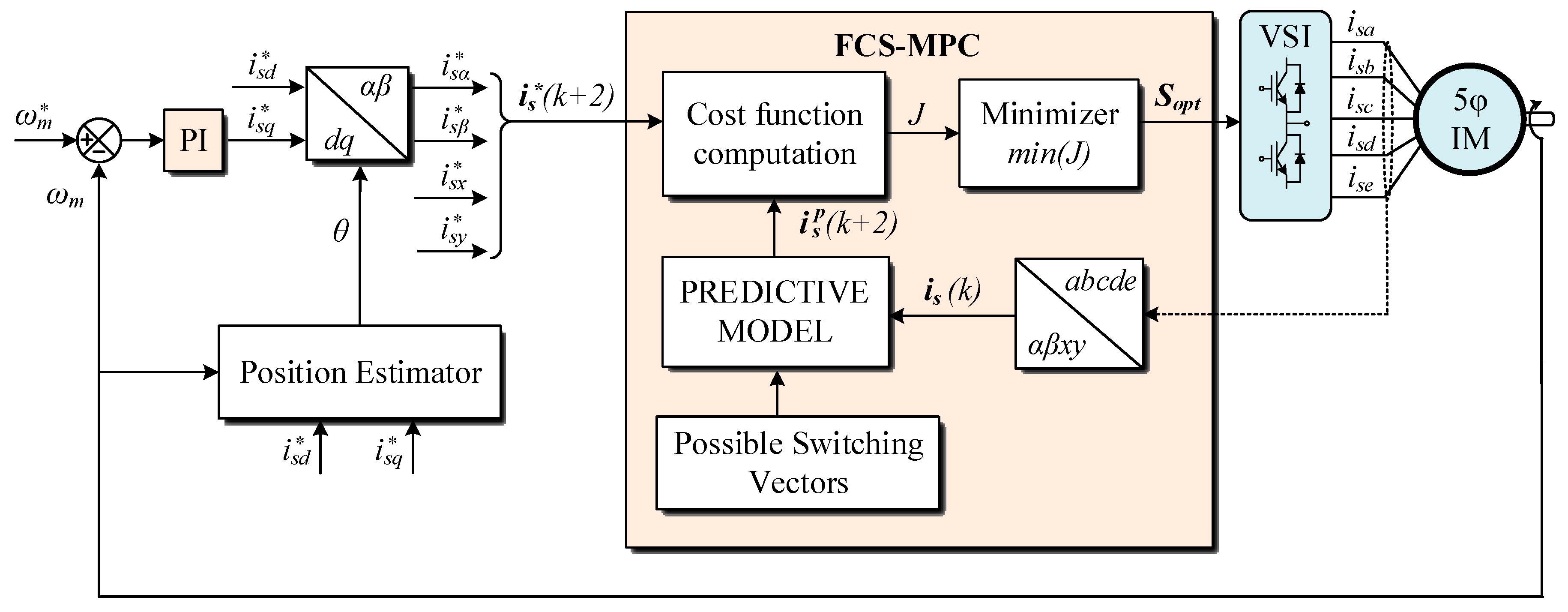
Figure 1. Finite control set model-based predictive control (FCS-MPC) control scheme for a five-phase IM drive fed using a voltage-source inverter (VSI).
Energies 12 04698 g001
Figure 2. Voltage vectors (VVs) in a five-phase IM drive: (upper plots) αβ and xy subspaces; (lower plot) defined VVs.
Energies 12 04698 g002
Figure 3. Control scheme of a five-phase IM drive using the direct torque controller (DTC) technique.
Energies 12 04698 g003
Figure 4. Experimental system.
Energies 12 04698 g004
Figure 5. Transition from prefault to postfault operation using a DTC controller with VVs. The fault occurs at t = 0.2 s; the speed is set to 500 rpm and a load torque around 60% of the nominal one is applied. (a) Measured speed ( ω m ) and its reference ( ω m * ); (b) estimated torque ( T ^ e ) and its reference ( T e * ); and (c) stator currents in the α–β and x–y planes ( i α β s ,   i x y s ).
Energies 12 04698 g005
Figure 6. Phase currents i b s , i c s , i d s and i e s in the transition from prefault to postfault operation using DTC with VVs (the faulty phase, i a s , has similar behavior before the fault appears, being null after the fault). The fault occurs at t = 0.2 s, the speed is set to 500 rpm and a load torque around 60% of the nominal one is applied.
Energies 12 04698 g006
Figure 7. Speed step response in open-phase fault operation of the proposed DTC controller. The reference speed is changed from 0 to 500 rpm at t = 0.2 s and no load torque is imposed. (a) Measured speed ( ω m ) and its reference ( ω m * ); (b) estimated torque ( T ^ e ) and its reference ( T e * ); (c) stator flux in the αβ plane; (d) phase currents.
Energies 12 04698 g007
Figure 8. Load-torque rejection response in open-phase fault operation of the DTC controller with VVs. A change from 0 N·m to around 60% of the nominal torque is applied at t = 0.8 s. (a) The measured speed ( ω m ) and its reference ( ω m * ). (b) The estimated torque ( T ^ e ) and its reference ( T e * ).
Energies 12 04698 g008
Figure 9. Speed reversal test in open-phase fault operation of the proposed DTC controller. The reference speed is changed from 500 to −500 rpm at t = 0.2 s and no load torque is imposed. (a) Measured and reference speed; (b) estimated torque ( T ^ e ) and its reference ( T e * ); (c) stator flux in the αβ plane; (d) phase currents.
Energies 12 04698 g009
Table 1. Lookup table for the DTC controller in healthy operation.
d λ s d T e d ω m Position of Stator Flux (Sector)
12345678910
+1+1+1VV3VV4VV5VV6VV7VV8VV9VV10VV1VV2
−1VV2VV3VV4VV5VV6VV7VV8VV9VV10VV1
−1+1VV9VV10VV1VV2VV3VV4VV5VV6VV7VV8
−1VV10VV1VV2VV3VV4VV5VV6VV7VV8VV9
0+1V0V31V0V31V0V31V0V31V0V31
−1V0V31V0V31V0V31V0V31V0V31
−1+1+1VV4VV5VV6VV7VV8VV9VV10VV1VV2VV3
−1VV5VV6VV7VV8VV9VV10VV1VV2VV3VV4
−1+1VV8VV9VV10VV1VV2VV3VV4VV5VV6VV7
−1VV7VV8VV9VV10VV1VV2VV3VV4VV5VV6
0+1V31V0V31V0V31V0V31V0V31V0
−1V31V0V31V0V31V0V31V0V31V0
Table 2. Electrical and mechanical parameters of the five-phase IM.
ParameterValueUnit
Stator resistance, Rs12.85Ω
Rotor resistance, Rr4.80Ω
Stator leakage inductance, Lls79.93mH
Rotor leakage inductance, Llr79.93mH
Mutual inductance, Lm681.7mH
Moment of inertia, J0.02kg·m2
Number of pole pairs, p3-
Rated torque, Tn4.70N·m
Rated stator flux, λs*0.389Wb