Article

Effects of Bounded Uncertainties on the Dynamic Characteristics of an Overhung Rotor System with Rubbing Fault

1
Centre for Efficiency and Performance Engineering, University of Huddersfield, Queensgate, Huddersfield HD1 3DH, UK
2
Institute of Vibration Engineering, Northwestern Polytechnical University, Xi’an 710072, China
3
Tianjin Key Laboratory of Power Transmission and Safety Technology for New Energy Vehicles, School of Mechanical Engineering, Hebei University of Technology, Tianjin 300401, China
*
Author to whom correspondence should be addressed.
Energies 2019, 12(22), 4365; https://doi.org/10.3390/en12224365
Submission received: 25 October 2019 / Revised: 11 November 2019 / Accepted: 12 November 2019 / Published: 15 November 2019

Abstract

:
This paper investigated the nonlinear vibrations of an uncertain overhung rotor system with rub-impact fault. As the clearance of the rotor and stator is getting smaller, contact between them often occurs at high rotation speeds. Meanwhile, inherent uncertainties in the rubbing can be introduced for a variety of reasons, and they are typically restricted to small-sample variables. It is important to gain a robust understanding of the dynamics of such a system under non-probabilistic uncertainties. A non-intrusive uncertainty quantification scheme, coupled with the Runge-Kutta method, was used to study the effects of the rub-impact related interval uncertainties on the dynamical response individually and simultaneously, including the uncertainties in the contact stiffness, clearance, and friction coefficient. Moreover, the numerical validation of the developed analysis method was verified through comparisons with the scanning approach. The results obtained provide some guidance for investigating the uncertain dynamics of rubbing rotors and diagnosing the rub-impact fault under non-random uncertainty.

1. Introduction

As engines are getting more and more compact, the clearance between the stator and rotor has been reduced to a very small value. When the rotor operates at high rotation speeds, the vibrations caused by assemble errors or typical faults, such as mass imbalance, will become prominent and the amplitudes will reach the clearance limit easily [1,2,3]. Then, contact between the rotor and stator occurs, often referred to as rub-impact [4,5,6]. Rubbing events in rotor systems may lead to instabilities, blade fracture, and even catastrophic disasters [7,8,9]. In order to understand the rubbing mechanism, as well as the rich nonlinear behaviors, many researchers have carried out investigations for dynamic analyses and rubbing fault diagnosis [10,11,12,13,14,15]. The effects of different rubbing forms on the dynamics of rotor systems were studied in depth by Ma et al. [16,17]. Then, relevant nonlinear dynamics were intensively investigated, including the unbalanced dynamical responses, critical speeds, and whirling orbits. Fay et al. [18] presented a numerical tool for the predictions of unstable regions related to the rotational speed. An aero-engine dual-rotor system with rub-impact was studied by Sun et al. [19]. These contributions provided insights of the nature of the rubbing faults.
In engineering complicated machineries, the parametric uncertainties can be introduced in many ways [20,21,22]. The influences of them on the dynamics of mechanical systems should not be neglected to achieve robust assessments [23,24,25,26]. In recent years, some researchers have drawn their attention to the uncertainty quantifications in the field of rotordynamics [20,27,28,29,30,31]. However, it is worth pointing out that most of these works were accomplished in the probability frame. Probabilistic methods often require the rigorous probability density function of uncertainty, which is established on the basis of large number of samples. In the practical applications, the number of specimen is limited in aero-engine rotating systems, which can be categorized as the small-sample-sized variables. Therefore, such probabilistic distribution models will be very difficult to construct or the expense will be high to produce sufficient number of samples. The interval approaches may be more useful in such cases as they rely only on the bounds of uncertainties [32]. Dimarogonas was the first to introduce interval analysis into rotordynamics [33]. Fu et al. [28,34] developed the interval precise integration method to calculate the uncertain transient responses and also a surrogate for the nonlinear dynamics of a cracked rotor. The stochastic response of a rubbing rotor/stator system was investigated by Zhang et al. [35]. A likelihood method was established to address the rubbing problem with mixed uncertainties in aspects of risk and reliability estimations [36]. Sinou et al. [37] investigated the stochastic nonlinear responses of a flexible rotor system with non-regular nonlinearities. As can be seen from the literature, the uncertain nonlinear behaviors of a rubbing rotor considering non-probabilistic uncertainties have not been fully revealed, especially the interval unbalanced dynamic responses. For this paper, we were motivated to investigate the effects of bounded uncertain parameters on the nonlinear responses of a rub-impact rotor system with an overhung disk using the non-intrusive interval uncertainty propagation method. There were two specific research objectives. The first was to analyze the interval nonlinear responses of an overhung rotor system considering the bounded uncertainties related to the rubbing event. The second was to justify the effectiveness and ability of the interval uncertainty analysis method in the prediction of response ranges for the non-smooth nonlinear rubbing problems. Various cases were investigated and compared for different uncertain parameter sets. In the uncertainty analysis method, computational efficiency improvement of simulations in the multi-dimensional uncertain cases has been achieved by truncating the tensorial sample candidates to an optimal size. For the present study, there were three hypotheses made. First, the mass disk is a rigid body without deformation while the casing is assumed to be rigid, but its surface can deform marginally subject to a rubbing event. Second, the torsional and axial vibrations of the rotating shaft can be ignored. Third, the uncertain parameters in the rotor system are independent to each other, i.e., they vary in their own respective manners without correlations.
The rest of the content is organized as follows. First, the rubbing model and the equations of motion of the overhung rotor system are established in Section 2. Then, in Section 3, the interval nonlinear dynamics of the system considering bounded uncertainties are derived based on the Chebyshev formulation. The numerical results for different cases and discussions are presented in Section 4. Lastly, the main conclusions and outlook for future research are given.

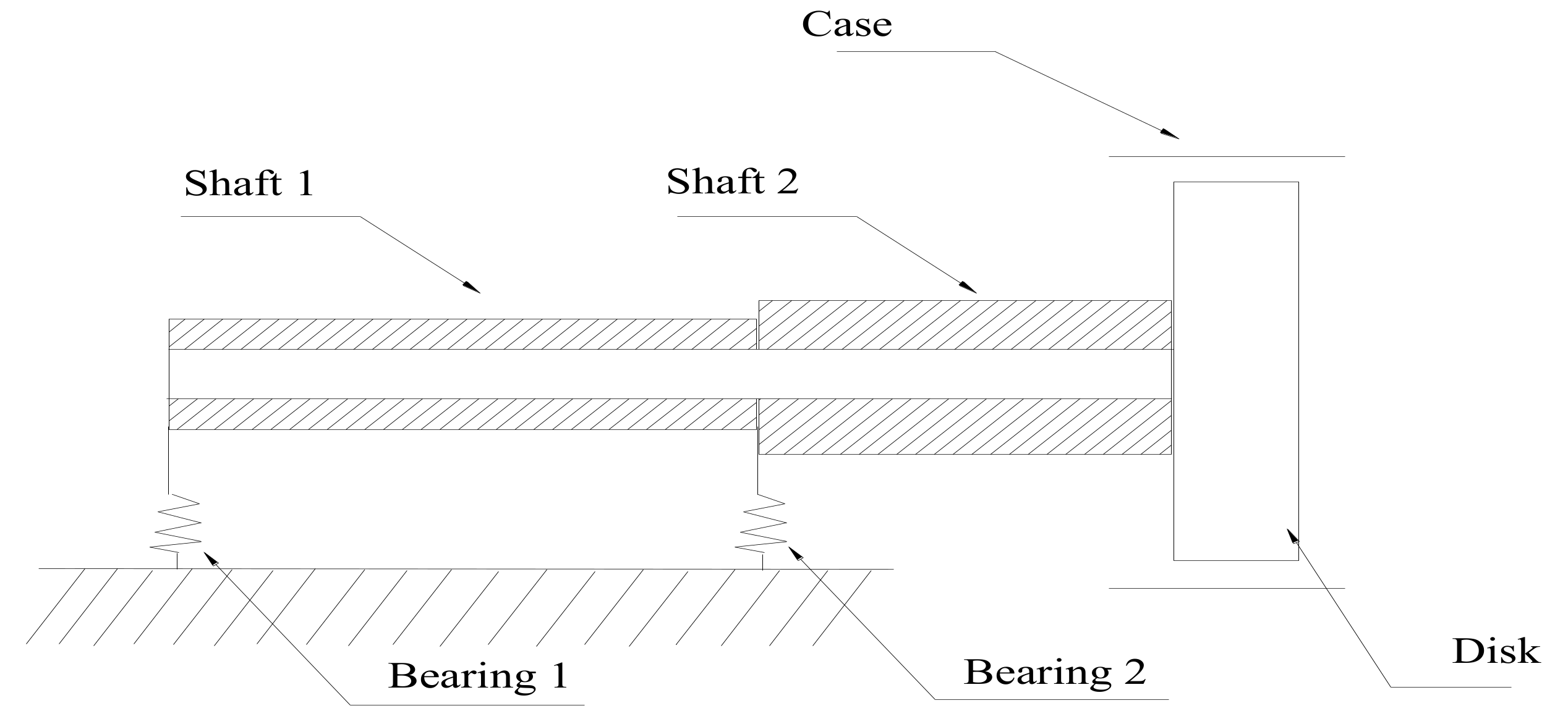
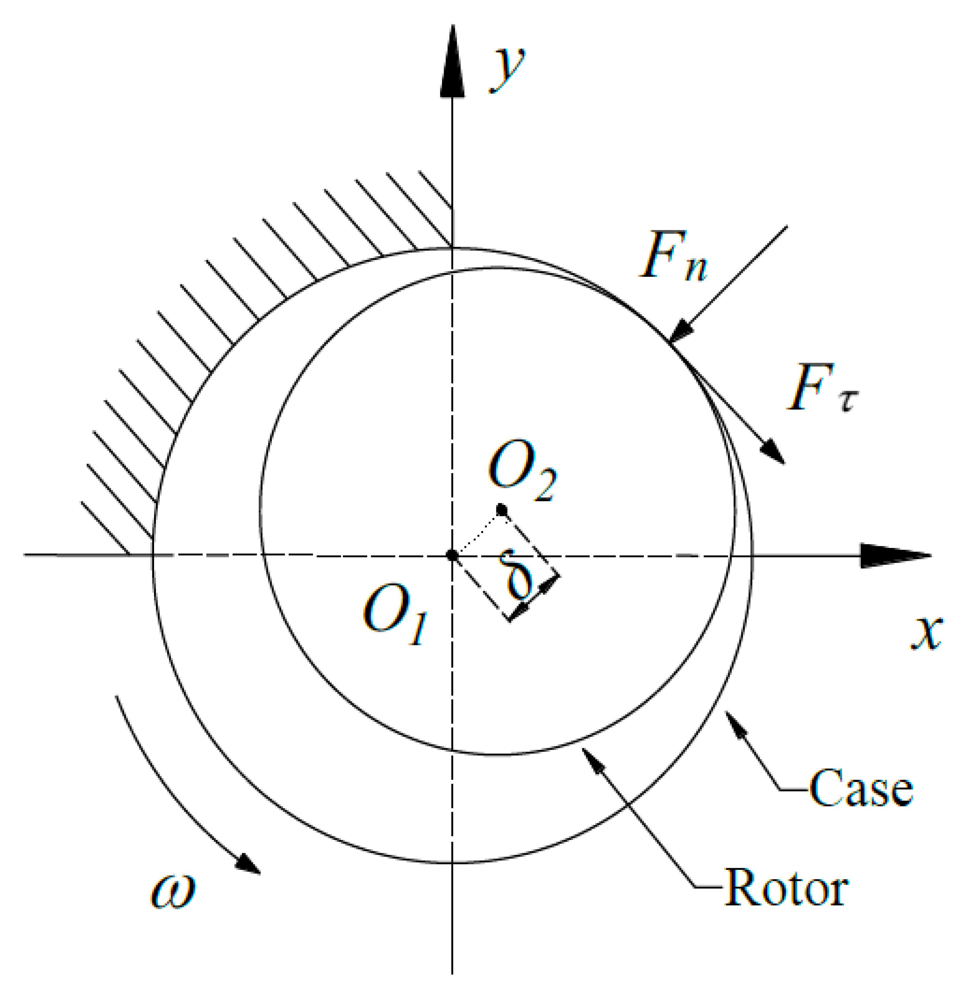
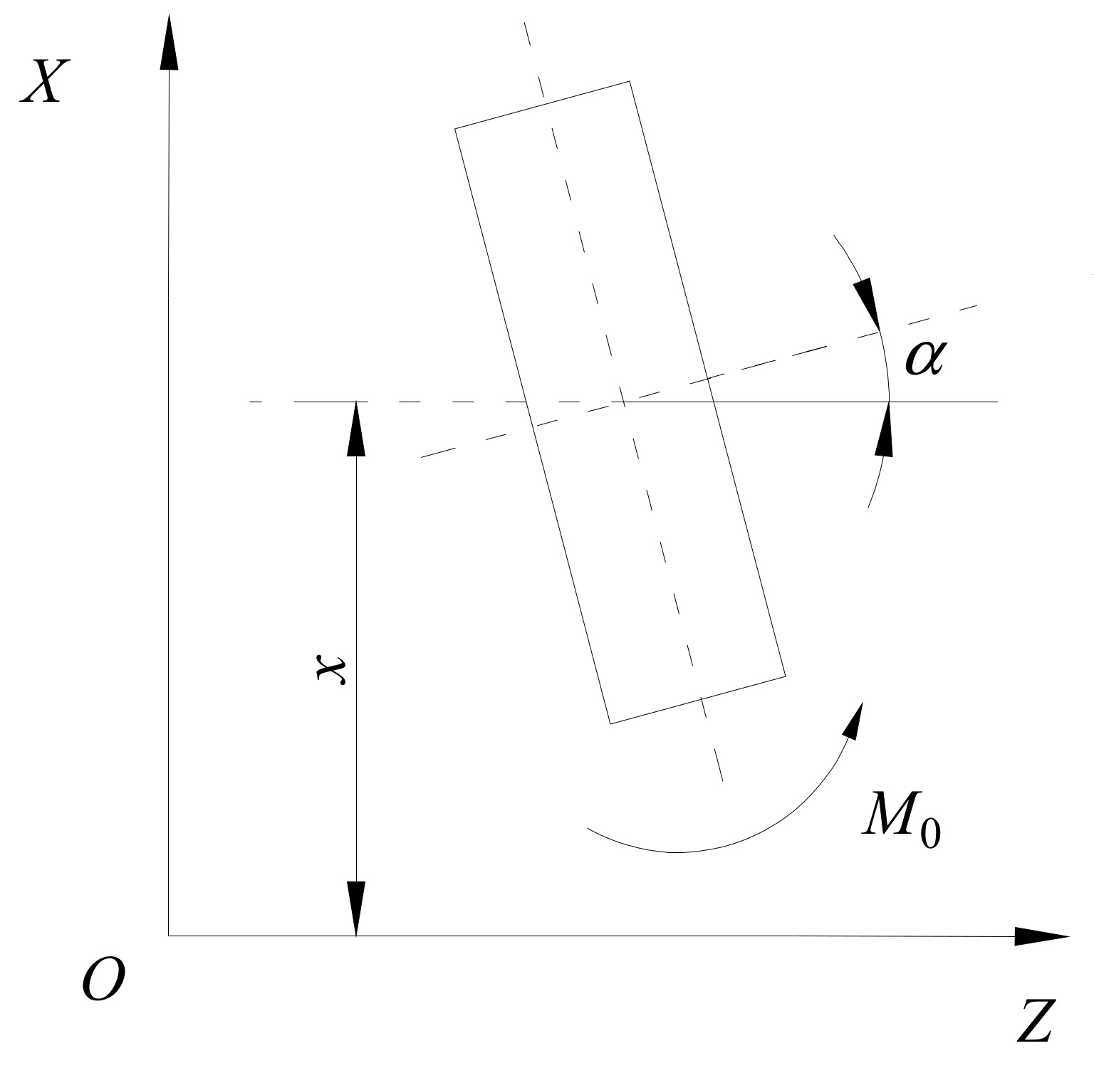
2. Motion Description of the Rubbing Rotor

A hollow-shaft rotor with overhung disk was considered in this study, which is shown in Figure 1. The system is simplified from an oxygen pump and represents a typical overhung configuration widely employed in industry [13,34]. It is supported by two isotropic linear bearings with the same stiffness in both x and y directions. The mass of the disk is m, and the polar and transverse moments of inertia of it are J p and J d . Damping effect is integrated into the viscous damping c. A casing is assembled alongside the mass disk and the clearance between the rotor and the casing is described by δ . They contact when the vibration amplitude of the rotor reaches the limit. The reacting forces during contact are illustrated in Figure 2.
The transfer matrix method (TMM) can be conveniently applied here to derive the governing equations of motion (EOM) of the system. In TMM, every featured cross-section has four motion displacements, i.e., two translate displacements and two rotation angles. Its major advantage is that the dimension of calculation matrices stays constant regardless of the number of degrees-of-freedom (DOFs) in the rotor system. The disk can be modeled by external incremental to the motion status vector. Denoting the displacement vector of the disk by [ x ,   α ,   y ,   φ ] T , where x ,   y are the lateral displacements, and α and φ are the rotational displacements around the y and x axes. To provide more information on the rotational displacement, Figure 3 shows the motion of the rigid disk in the OZX plane where the lateral displacement x and rotational displacement α are included. It is similar in the OZY plane. Take the mass of the elastic shafts into consideration, the time-varying motion equations of the rotor system can be expressed as
m x ¨ + c x ˙ + k 11 x + k 12 α = m e ω 2 cos ( ω t ) + F x J d α ¨ + J p ω φ ˙ + k 21 x + k 22 θ = 0 m y ¨ + c y ˙ + k 11 y + k 12 φ = m e ω 2 sin ( ω t ) + F y m g J d φ ¨ J p ω α ˙ + k 21 y + k 22 φ = 0 ,
where F x and F y are the nonlinear forces induced by the rubbing, ω is the angular speed, and e is the imbalance on the disk. The stiffness parameters k i j ,   i , j = 1 , 2 are elements derived using the TMM from the left side of the rotor to the right side [34].
For a predefined clearance δ , if the radial deflection of the disk geometric center r = x 2 + y 2 is less than the clearance value, then F x = F y = 0 and the rotor system will vibrate linearly. When r δ holds true, the rub-impact forces are given by [8,16,19]
F n ( x ,   y ) = k c ( r δ ) F τ = μ F n ,
where k c is the contact stiffness, and μ is the friction coefficient related to forces tangential to the impact. In a uniform way, the rub-impact forces on the rotor can be projected on the coordinates as
F x F y = ( 1 δ r ) k c H ( r δ ) 1 μ μ 1 x y ,
where H ( ν ) is the Heaviside function
H ( ν ) = 0 , ν < 0 1 , ν 0 .
To obtain the steady-state vibration response of the rotor, the fourth order Runge-Kutta method (RK4) is used to solve Equation (1). The rotor/case contact stiffness, friction coefficient, and clearance value for the rotor under study are set as k c = 1.25 × 10 7   N / m , μ = 0.2 , and δ = 4 × 10 5   m . The imbalance is considered only on the disk, and the eccentricity is 0.001 m with an initial angle zero. The length and radius for shaft 1 and 2 are 0.3 m, 0.02 m, and 0.12 m, 0.03 m, respectively. The inner radius of two shafts is 0.01 m. The disk has a mass 8.4 kg, and the polar and diameter moments of inertia are 0.0695 kg/m2 and 0.0357 kg/m2, respectively. Viscous damping at the disk is considered, and its value is 120 N·s/m. The stiffness values for bearing 1 and 2 are 1 × 10 8 N/m and 1 × 10 6 N/m.

3. Nonlinear Vibrations Under Uncertainty

In this section, the uncertainties in the rubbing rotor will be described first. We will focus on the crucial parameters related directly to the rub-impact as the effects of the regular uncertain physical parameters are intensively investigated in the stochastic domain [30,38,39]. Then, the non-intrusive uncertainty analysis procedure will be explained for the nonlinear dynamics. Some manipulations are incorporated, as well, to decrease the computational cost.

3.1. Bounded Uncertainties in Rubbing Fault

There are three critical parameters involved in the rub-impact between the rotor and case, i.e., the clearance, the contact stiffness, and the friction coefficient. They are inherently subject to uncertainties induced by wear of rotor blades, material degradation, and assemble errors. Meanwhile, the complete statistical information for these uncertainties is difficult to obtain, and the probabilistic methodologies will fail in such cases. Thus, we model the uncertainties by uncertain-but-bounded quantities, which are defined by their upper and lower limits. For the bounded clearance, we can write it in interval form:
δ I = [ δ _ ,   δ ¯ ] = [ δ c β δ δ c ,   δ c + β δ δ c ] ,
where I denotes an interval parameter, the δ _ ,   δ ¯ , and δ c are the lower bound, upper bound, and mid-value of δ I , respectively. The uncertain coefficient β δ for bounded clearance is a small percentage.
Considering uncertainty in the contact stiffness, the interval stiffness can be expressed as
k c I = [ k _ c ,   k ¯ c ] = [ k c c β k k c c ,   k c c + β k k c c ] ,
in which k _ c ,   k ¯ c , and k c c are the lower bound, upper bound, and mid-value of k c I , respectively. Symbol β k is the uncertain coefficient of interval contact stiffness.
Similarly, bounded friction coefficient is given by
μ I = [ μ _ ,   μ ¯ ] = [ μ c β u μ c ,   μ c + β u μ c ] ,
where μ _ ,   μ ¯ , and μ c are the lower bound, upper bound, and mid-value of μ I , respectively. Notation β u is the uncertain coefficient of bounded friction coefficient.

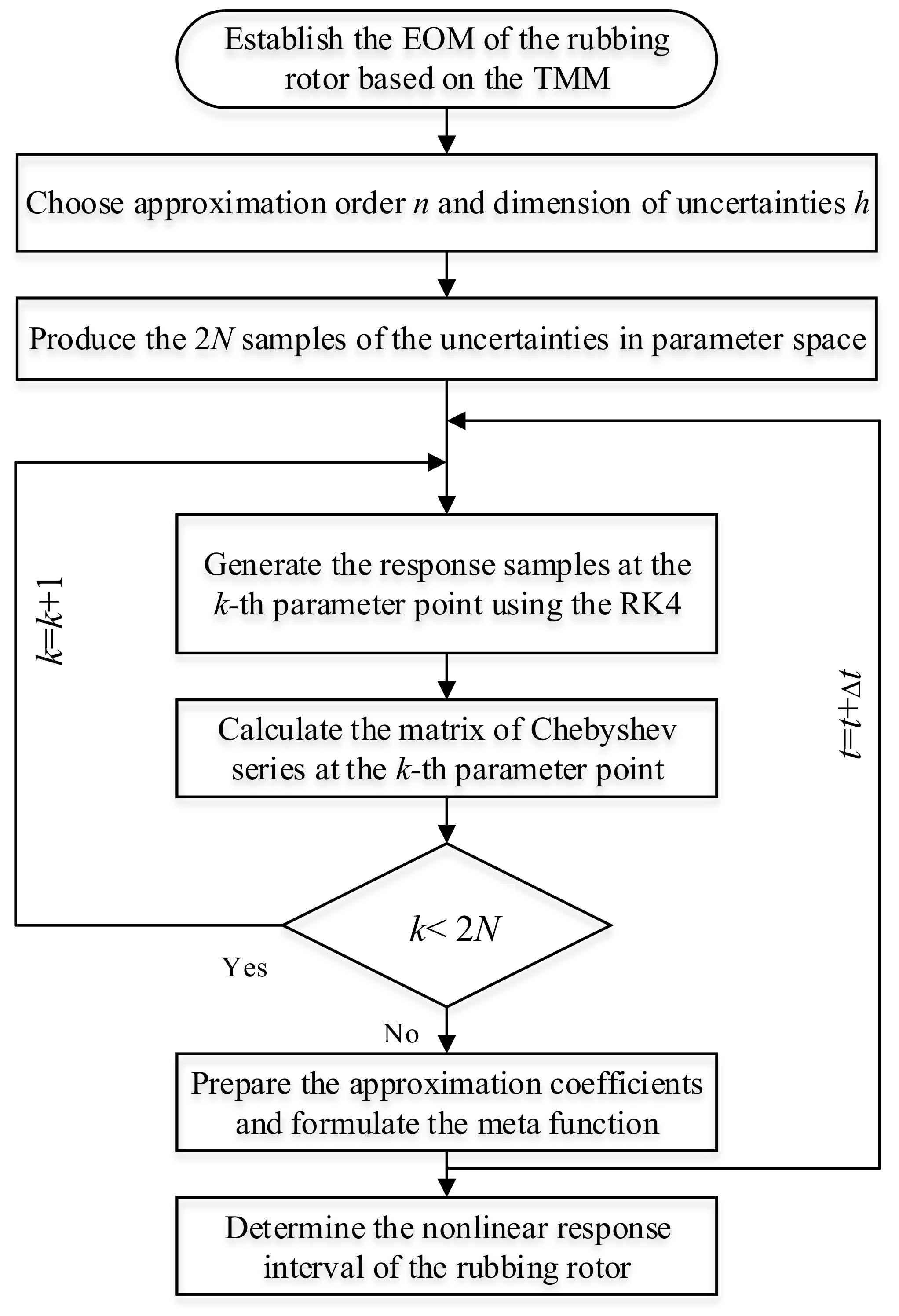
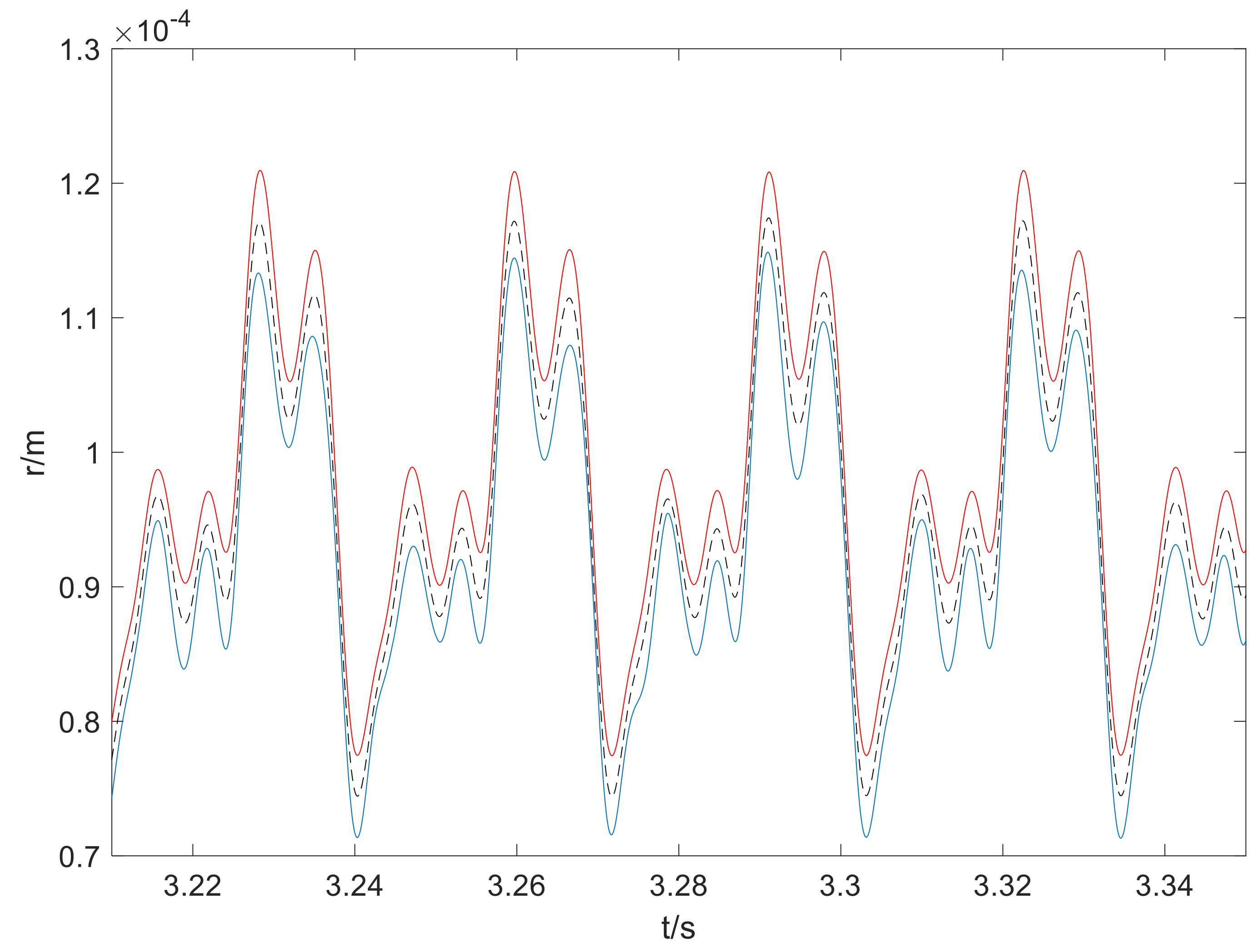
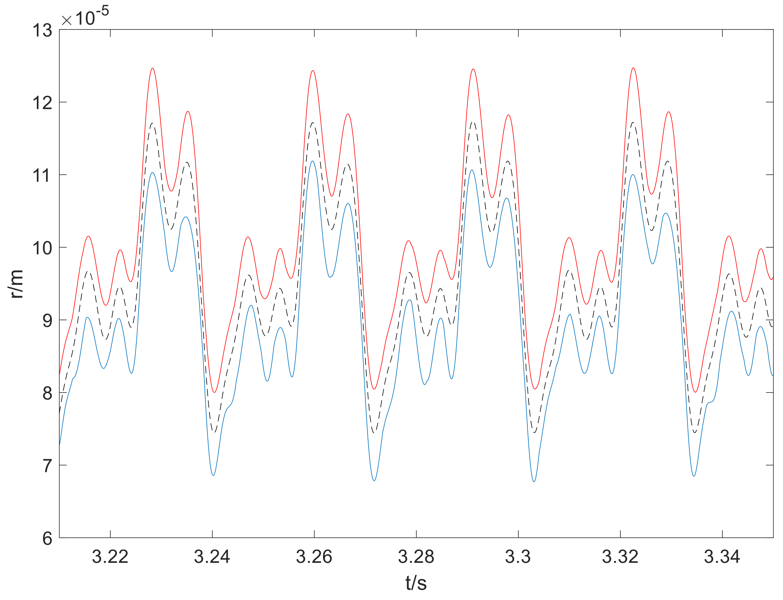
3.2. Uncertainty Analysis of the Response

The dynamic behaviors of the rotor will be nonlinear due to the non-smooth rubbing forces and it is a challenge for the uncertainty analysis procedure to accurately predict the response range. Generally, the intrusive methodologies, such as the Taylor perturbation method, can provide fair estimations, but the implementation is not convenient [32]. On the other side, the non-intrusive interval approaches are adaptive and easy to use while prone to introduce overestimations [34], especially for highly nonlinear dynamic problems. The Chebyshev inclusion function [40], suitable for nonlinear problems, works non-intrusively and can be incorporated with collocation skills to reduce computation cost [41]. When the physical parameters are considered uncertain, the nonlinear response output can be regarded as a continuous function of the bounded uncertainties. However, the unique and rigorous explicit expression for it cannot be determined beforehand. Suppose the uncertain response distribution function can be approximated by the Chebyshev orthogonal polynomial expansion; then the deterministic rubbing rotor will be used as a black box avoiding modifications to the established solver. For this purpose, an approximation for the uncertain responses (referring to any of the four displacements expressed in Equation (1) or the radial deflection r ) considering single bounded parameter can be formulated as
R ( ξ ) = f 0 2 + i = 1 n f i C i ( ξ ) ,   ξ [ 1 ,   1 ] ,
ξ = 2 a ( a ¯ + a _ ) a ¯ a _ ,   a a I = [ a _ ,   a ¯ ] ,
where n is the desired order, and a is an uncertain variable corresponding to any of the practical bounded parameters expressed in Equations (5)–(7). The C ( ξ ) represents the Chebyshev orthogonal polynomial C ( ξ ) = cos ( i arccos x ) ) . In recurrence form, it is given as
C 0 ( ξ ) = 1 ,   C 1 ( ξ ) = ξ C i + 1 ( ξ ) = 2 ξ C i ( ξ ) C i 1 ( ξ )   .
Notation f i is the expansion coefficient, which can be obtained by the Gauss-Chebyshev quadrature
f i = 2 p k = 1 p R ( ξ ˜ k ) C i ( ξ ˜ k ) ,
where ξ ˜ k is the collocation point generated by the roots of the (p + 1)-th Chebyshev polynomial
ξ k = cos ( 2 k 1 2 p π ) ,   k = 1 ,   2 ,   ,   p .
Herein, we set p = n + 1 to improve efficiency, which is the minimum requirement in order to be accurate. In Equation (2), C i ( ξ ˜ k ) is the value of the Chebyshev polynomial at collocations and R ( ξ ˜ k ) should be calculated by the distribution function, which is unknown. However, at the specific point, the response value can be derived by the deterministic system. To this end, we first transform the collocation point to its corresponding physical parameter:
a k = a _ k + a ¯ k 2 + a ¯ k a _ k 2 ξ k .
In this manner, the uncertain parameter is specified as a deterministic value, and then the R ( ξ ˜ k ) can be calculated by Equation (1). Currently, the approximation function of the nonlinear uncertain response is established, and the spreading interval can be determined by searching the extreme values. Moreover, it can reduce overestimations caused by the interval arithmetic used in [34,40]. Taking multiple bounded parameters into consideration, the manipulations of the collocation points and projections should be written in vector form:
ξ = 2 α ( α ¯ + α _ ) α ¯ α _ , α α I = [ α _ , α ¯ ] .
It is worth mentioning that the calculation is still completed with respect to every element. The multi-dimensional Chebyshev polynomials are consequently written as
C i 1 i 2 i h ( ξ ) = C i 1 ( ξ 1 ) C i 2 ( ξ 2 ) C i h ( ξ h ) ,
where h denotes the number of considered uncertainties. Generally, the collocation points grow in a tensor way in comparison with single uncertainty problems. For example, there are at least ( n + 1 ) h samples for the h-dimensional uncertain problem. The computation cost will increase enormously with the dimension and expansion order, which may discourage its application. Therefore, an extra scheme that attempts to reduce the computational burden is needed, such as the sparse grid method. The Chebyshev collocation method [41] provides a good solution to this problem. For a predefined approximation order n, we delete the terms in the tensor product of Equation (8), whose order is higher than n, and the least-term expression is obtained:
R ( ξ ) = 0 i 1 + + i h n 1 2 λ Γ i 1 , , i h C i 1 , , i h ( ξ ) ,   ξ [ 1 , 1 ] h ,
where λ equals to the number of appearance of 0 in the index set i 1 i 2 i h . The total number of terms in Equation (7) is N = ( n + h ) ! / ( n ! h ! ) and so is the number of unknown coefficients Γ i 1 , , i h . The optimal amount of collocations is two times the number of unknowns.
Then, the coefficient vector can be calculated by regression formulas:
Γ = ( Λ T Λ ) 1 Λ T R ˜ ( ξ ^ )
where ξ ^ denotes the truncated collocation point sets, and Λ is expressed as
Λ = C 0 , , 0 ( ξ ˜ 1 ) C 1 , , 0 ( ξ ˜ 1 ) C i 1 , , i h ( ξ ˜ 1 ) C 0 , , n ( ξ ˜ 1 ) C 0 , , 0 ( ξ ˜ 2 ) C 1 , , 0 ( ξ ˜ 2 ) C i 1 , , i h ( ξ ˜ 2 ) C 0 , , n ( ξ ˜ 2 ) C 0 , , 0 ( ξ ˜ 2 N ) C 1 , , 0 ( ξ ˜ 2 N ) C i 1 , , i h ( ξ ˜ 2 N ) C 0 , , n ( ξ ˜ 2 N ) ,
ξ ˜ j = [ ξ ˜ 1 j ,   ξ ˜ 2 j ,   ,   ξ ˜ h j ] T ,   j = 1 ,   2 ,   ,   2 N .
The R ˜ ( ξ ^ ) represents the deterministic nonlinear response vector drawn at the collocation points. Similar to the single uncertainty case, the response range can be easily obtained:
R I ( α I ) = [ min ( R ( α ) ) ,   max ( R ( α ) ) ] .
From the above deduction, we can notice that the uncertainty analysis procedure developed does not break into the descriptions of the original rotor system, namely Equation (1). It will be quite convenient for engineering problems, especially when the solution process is rather complicated. For the better reader comprehension, the computational flowchart of the framework is demonstrated in Figure 4. Generally, the overestimations of the non-intrusive methods in nonlinear problems are usually significant, and high orders may be necessary to converge. The numerical performance of this approach will be tested for the rubbing rotor dynamical problems in the simulations.

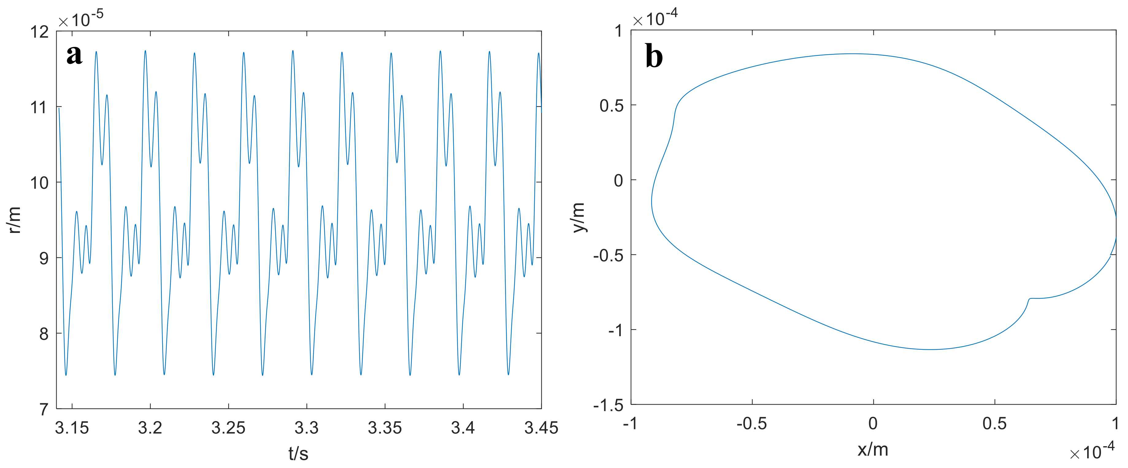
4. Numerical Results

In this section, the effects of the bounded uncertainties in fault relevant physical parameters on the nonlinear response are investigated based on the fixed physical parameters given in Section 2. Firstly, the deterministic response is illustrated to characterize the rubbing rotor system without uncertainty and to give an initial impression of its dynamic behaviors. Based on the deterministic model and numerical simulations, the steady-state vibration amplitude time history of the disk geometric center and its orbit at ω = 200   rad / s are plotted in Figure 5. In Figure 5, the initial periods are skipped to eliminate transient effects. We can see from Figure 5 that the vibration response time history is affected by the rub-impact, and multiple frequencies can be found. The orbit is no longer an ellipse, and the response can exhibit rich nonlinear characteristics.
For the following of this part, the three bounded uncertainties will be investigated, respectively, as well as simultaneously. In single uncertainty cases, an order 3 in Equation (2) will be used. Figure 6 presents the interval response of the rubbing rotor with 5% bounded uncertainty in the clearance between the rotor and case. In Figure 6, the deterministic response is also provided in black dotted line for reference. The upper bound is plotted in red solid line, and the lower in blue solid line. It is similar in the forthcoming uncertain simulations. From Figure 6, we can observe that, due to the uncertainty, the dynamic response is enveloped in an interval. Precise enclosure of the nominal curve is evidenced in all the time history, despite the complexity in vibrational response curves introduced by the nonlinear nature. The dynamic response is globally influenced in the time history, and the upper and lower bounds are not necessarily symmetric about the nominal line. The peak values, including the upper and lower ones, are deviated more significantly. It is demonstrated that the uncertainty in the clearance is a crucial factor for the dynamic behaviors of the rubbing rotor system. Then, we investigated the effects of the bounded friction coefficient when the uncertain degree is set as the same value of 5%. Based on the calculation procedure, the results are given in Figure 7. An important feature that should be noticed in Figure 7 is that the response range pattern is obviously different compared with Figure 6. The influences of the non-probabilistic uncertainty in friction coefficient are mainly demonstrated around the peaks and anti-peaks, while in other areas the interval bounds distribute closely to the deterministic line. Overall, the deviations of the amplitudes are not significant. To further study its effects, Figure 8 shows the interval results when the uncertain degree for friction coefficient is 10%. From Figure 8, it can be seen that the deviations are greater than in Figure 7, induced by the larger variations in the parameter. This phenomenon can also be interpreted as the uncertainty in friction coefficient is less sensitive than that of the clearance. However, its impacts on the amplitudes of resonant peaks cannot be neglected.
Figure 9 gives the simulation results with 5% bounded uncertainty in the contact stiffness of the rotor and case. It can be seen that the dynamic response range is influenced in the complete time history, which is even more significant than in the uncertain clearance case. That is mainly due to the crucial role the contact stiffness played in a rub-impact event. Special attention should be paid to this parameter in the analysis of the deterministic and uncertain dynamics of a rubbing rotor system. In this condition, we would like to test the accuracy of the uncertainty analysis procedure in such a sensitive and nonlinear case. The reference solutions are generated by the interval scanning method, which draws samples for an interval variable with equal distance. For a more insightful observation of the difference between the results obtained from the two interval methods, we calculated the relative difference rate, which is shown in Figure 10, by considering the results from the 100-points scanning method as accurate. The latter has been verified to be convergent with results calculated using more samples. From Figure 10, it is illustrated that the proposed analysis method has excellent accuracy in prediction of the uncertain nonlinear response bounds. The errors for the upper bound is very small and negligible. Greater errors are found in the lower bound, and they reach peak values as the deterministic curve gets close to peaks. However, the errors are all below 1.2%, and it is satisfactory since only order 3 in the interval method is applied. The calculation burden for the two methods are not comparable as running of the deterministic model four times is needed in the method proposed, while 100 times is required in the scanning method. The above discussions provide verification to the accuracy and efficiency of the non-intrusive uncertainty propagation approach.
Figure 11 shows the response intervals of the rotor system at ω = 200   rad / s considering the three bounded uncertainties described in Section 3.1, with the uncertain coefficient 5% to all. This multi-uncertain-variable problem combines the effects of the previous cases. It was noticed that multi-uncertain parameters will bring extra variations in the dynamic behaviors of the rubbing rotor, and a wide range is demonstrated. Some distortions are observed, as well, in the lower bound of the response. According to the results, it is important to take the uncertainties into consideration for the dynamic analysis and rubbing fault diagnosis of rotating machineries in engineering context. In Figure 12, we give the response ranges for ω = 225   rad / s , with only 2% uncertainties in the same three parameters. The revolution speed is carefully chosen based on extra simulations (not presented here) to allow analysis of the system when it is sensitive to variabilities in physical parameters. The uncertain degree is also set to the value of 2% to demonstrate the propagations of small range uncertainties in sensitive case. We can notice from Figure 12 that the amplitudes and response ranges of vibration are large though the uncertain degree is decreased. There are high-amplitude bands during a complete period, and the deterministic curve is not placed in the middle. These characteristics will have significant influences on the dynamics and diagnosis of rub-impact faults.

5. Discussions

In the context of rotor systems with typical faults, the effects of parametric uncertainties on the nonlinear dynamic responses have been widely investigated using the stochastic methods, such as cubic nonlinearity, misalignment, and initial bow [30,35,36,37]. However, there are many situations where the probability-based uncertainty analysis methods are found difficult to implement due to the absence of essential statistical information. The uncertainty analysis method developed in this study avoids the hash demands, with only the varying limitations of variables needed. Moreover, the property of non-intrusive calculation benefits the implementation and makes the method a universal tool for other similar uncertain nonlinear problems. In a previous study of a rotor/stator contact problem under random uncertainty [35], the derivative-based Taylor expansion method was used to analyze the first two statistical moments, considering the randomness in support stiffness, damping, contact stiffness, and unbalance. In large-scale systems [19], the derivative information can be difficult to obtain. For the perturbation techniques, the computational accuracy cannot be guaranteed if large variation coefficients are applied. The comparison with the scanning method in this study suggests that the calculation accuracy of the developed analysis method is satisfactory (below 1.2%) with large uncertainties although only low approximation order was used. Therefore, it could be a reference for uncertainty analysis in rubbing rotors under various conditions.
Reliability analysis of a rubbing Jeffcott rotor was conducted, and the safe and failure regions were studied [36]. Simulation on random responses with multiple random parameters was provided in [35]. However, the influences of individual uncertainties remain unknown. In this research, the uncertainties closely related to the rub-impact fault were considered, and their effects on the nonlinear responses were presented. The system responses are found to be quite sensitive to the interval uncertainty in the contact stiffness and then to the clearance. It is comparatively less significant of the response deviations when uncertain friction coefficient was considered under the same uncertain degree 5%. The simulations with three interval parameters suggest that small uncertainties may propagate and cause significant variabilities in the nonlinear response. An interesting phenomenon that should be noted in Figure 12 is that the positions of vibration peaks have been shifted, which are caused by the alterations in the natural characteristics of the rotor system [42]. Moreover, the upper bound and lower bound of the interval response are not necessarily symmetrical about its nominal curve. The results could help for the rub-impact fault diagnosing and dynamical characterization.

6. Conclusions

In this paper, the uncertain nonlinear vibration of a rubbing overhung rotor is investigated via the non-intrusive uncertainty propagation analysis. The dynamical characteristics of the rotor system with concurrent presence of rub-impact and interval uncertainties related to the fault are complicated due to the nonlinear nature. The numerical simulations show that the uncertainties have obvious impacts on the dynamic characteristics, and they can alter the pattern of vibrations, as well as the diagnosis of rub-impact fault. Specifically, the uncertainty in contact stiffness has the most significant effects, which is followed by uncertainty in the clearance. The variability in the friction coefficient has the least effects on the nonlinear vibrations compared with the former two uncertain parameters. Propagations of multiple sources of uncertainties can cause the dynamic responses of the system deviate significantly from the nominal curves, even though individual uncertainties have relatively small uncertain degrees. Comparison with the scanning method gives credit to the calculation accuracy and computational efficiency of the method developed. The largest relative errors are observed in the lower bounds but are no greater than 1.2%. The results obtained can be helpful for more comprehensive evaluations and understanding of the dynamics of the rubbing rotor with uncertainties taken into consideration. The uncertainty analysis method, which is non-intrusive in implementation and qualified for interval uncertainties spreading in large ranges, can be used to investigate other general nonlinear mechanical systems, as well. In future research, the inherent nonlinear behaviors under interval uncertainty, including the multi-solution evolutions with turning points and the stabilities of solutions, will be investigated by the predictor-corrector technique and non-intrusive approaches. Application of the uncertainty quantification frame to the practical aero-engine rotor systems with rub-impact under various working conditions will be carried out.

Author Contributions

Conceptualization, C.F. and D.Z.; methodology, C.F. and Y.Y.; software, C.F. and Y.Y.; validation, F.G. and A.B.; investigation, C.F. and D.Z.; data curation, F.G. and A.B.; writing—original draft preparation, C.F.; writing—review and editing, F.G. and A.B.

Funding

This research was funded by the National Natural Science Foundation of China, grant number 51605133, 11972295, and the Hebei Provence Science and Technology Support Program, grant number 17394303D.

Conflicts of Interest

The authors declare no conflict of interest.

References

  1. Xu, X.P.; Han, Q.K.; Chu, F.L. Review of electromagnetic vibration in electrical machines. Energies 2018, 11, 1779. [Google Scholar] [CrossRef]
  2. Hu, L.; Liu, Y.B.; Teng, W.; Zhou, C. Nonlinear coupled dynamics of a rod fastening rotor under rub-impact and initial permanent deflection. Energies 2016, 9, 883. [Google Scholar] [CrossRef]
  3. Wang, Z.L.; Yang, J.; Li, H.Y.; Zhen, D.; Xu, Y.D.; Gu, F.S. Fault identification of broken rotor bars in induction motors using an improved cyclic modulation spectral analysis. Energies 2019, 12, 3279. [Google Scholar] [CrossRef]
  4. Mokhtar, M.A.; Darpe, A.K.; Gupta, K. Experimental investigations on torsional vibrations of a rotor during a rotor-stator rub. In Proceedings of the International Conference on Rotor Dynamics, Rio de Janeiro, Brazil, 23–27 September 2018; pp. 534–544. [Google Scholar]
  5. Edwards, S.; Lees, A.W.; Friswell, M.I. The influence of torsion on rotor/stator contact in rotating machinery. J. Sound Vib. 1999, 225, 767–778. [Google Scholar] [CrossRef]
  6. Choy, F.K.; Padovan, J. Non-linear transient analysis of rotor-casing rub events. J. Sound Vib. 1987, 113, 529–545. [Google Scholar] [CrossRef]
  7. Jiang, J. The analytical solution and the existence condition of dry friction backward whirl in rotor-to-stator contact systems. J. Vib. Acoust. 2007, 129, 260–264. [Google Scholar] [CrossRef]
  8. Yang, Y.; Xu, Y.Q.; Yang, Y.R.; Cao, D.Q. Dynamics characteristics of a rotor-casing system subjected to axial load and radial rub. Int. J. Nonlinear Mech. 2018, 99, 59–68. [Google Scholar] [CrossRef]
  9. Yang, W.X.; Tian, W.Y.; Hvalbye, O.; Peng, Z.K.; Wei, K.X.; Tian, X.L. Experimental research for stabilizing offshore floating wind turbines. Energies 2019, 12, 1947. [Google Scholar] [CrossRef]
  10. Chu, F.L.; Lu, W.X. Experimental observation of nonlinear vibrations in a rub-impact rotor system. J. Sound Vib. 2005, 283, 621–643. [Google Scholar] [CrossRef]
  11. Ge, X.B.; Luo, Z.; Ma, Y.; Liu, H.P.; Zhu, Y.P. A novel data-driven model based parameter estimation of nonlinear systems. J. Sound Vib. 2019, 453, 188–200. [Google Scholar] [CrossRef]
  12. Hu, N.Q.; Chen, M.; Wen, X.S. The application of stochastic resonance theory for early detecting rub-impact fault of rotor system. Mech. Syst. Signal Process 2001, 17, 883–895. [Google Scholar] [CrossRef]
  13. Qin, W.Y.; Su, H.; Yang, Y.F. Grazing bifurcation and chaos in response of rubbing rotor. Chaos Solitons Fract. 2008, 37, 166–174. [Google Scholar] [CrossRef]
  14. Liu, Y.; Zhao, Y.L.; Lang, Z.Q.; Li, J.T.; Yan, X.X.; Zhao, S.Y. Weighted contribution rate of nonlinear output frequency response functions and its application to rotor system fault diagnosis. J. Sound Vib. 2019, 460, 114882. [Google Scholar] [CrossRef]
  15. Peng, Z.K.; Chu, F.L.; Tse, P.W. Detection of the rubbing-caused impacts for rotor–stator fault diagnosis using reassigned scalogram. Mech. Syst. Signal Process 2005, 19, 391–409. [Google Scholar] [CrossRef]
  16. Ma, H.; Zhao, Q.B.; Zhao, X.Y.; Han, Q.K.; Wen, B.C. Dynamic characteristics analysis of a rotor–stator system under different rubbing forms. Appl. Math. Model. 2015, 39, 2392–2408. [Google Scholar] [CrossRef]
  17. Sun, Q.; Ma, H.; Zhu, Y.P.; Han, Q.K.; Wen, B.C. Comparison of rubbing induced vibration responses using varying-thickness-twisted shell and solid-element blade models. Mech. Syst. Signal Process 2018, 108, 1–20. [Google Scholar] [CrossRef]
  18. Fay, R.; Kreuzer, D.; Liebich, R.; Wiedemann, T.; Werner, S. Numerical results of the influence of thermal effects on the turbo machine rotordynamics induced by light-rubs against a brush seal. J. Sound Vib. 2018, 425, 70–81. [Google Scholar] [CrossRef]
  19. Sun, C.Z.; Chen, Y.S.; Hou, L. Nonlinear dynamical behaviors of a complicated dual-rotor aero-engine with rub-impact. Arch. Appl. Mech. 2018, 88, 1305–1324. [Google Scholar] [CrossRef]
  20. Sinou, J.-J.; Nechak, L.; Besset, S. Kriging metamodeling in rotordynamics: Application for predicting critical speeds and vibrations of a flexible rotor. Complexity 2018. [Google Scholar] [CrossRef]
  21. Lin, S.-Y.; Lin, A.-C. Risk-kimiting scheduling of optimal non-renewable power generation for systems with uncertain power generation and load demand. Energies 2016, 9, 868. [Google Scholar] [CrossRef]
  22. Mazaher, H.B.; Yousefi, G.; Claus, B.; Jayakrishnan, R.P. Long term expected revenue of wind farms considering the bidding admission uncertainty. Energies 2016, 9, 945. [Google Scholar]
  23. Yang, Y.F.; Wu, Q.Y.; Wang, Y.L.; Qin, W.Y.; Lu, K. Dynamic characteristics of cracked uncertain hollow-shaft. Mech. Syst. Signal Process 2019, 124, 36–48. [Google Scholar]
  24. Lu, K.; Jin, Y.L.; Chen, Y.S.; Yang, Y.F.; Hou, L.; Zhang, Z.Y.; Li, Z.G.; Fu, C. Review for order reduction based on proper orthogonal decomposition and outlooks of applications in mechanical systems. Mech. Syst. Signal Process 2019, 123, 264–297. [Google Scholar] [CrossRef]
  25. Fu, C.; Xu, Y.D.; Yang, Y.F.; Lu, K.; Gu, F.S.; Ball, A. Response analysis of an accelerating unbalanced rotating system with both random and interval variables. J. Sound Vib. 2019, 466, 115047. [Google Scholar] [CrossRef]
  26. Qin, Z.Y.; Pang, X.J.; Safaei, B.; Chu, F.L. Free vibration analysis of rotating functionally graded CNT reinforced composite cylindrical shells with arbitrary boundary conditions. Compos. Struct. 2019, 220, 847–860. [Google Scholar] [CrossRef]
  27. Elishakoff, I.; Cai, G.Q.; Starnes, J.H., Jr. Non-linear buckling of a column with initial imperfection via stochastic and non-stochastic convex models. Int. J. Nonlinear Mech. 1994, 29, 71–82. [Google Scholar] [CrossRef]
  28. Fu, C.; Ren, X.M.; Yang, Y.F.; Lu, K.; Qin, W.Y. Steady-state response analysis of cracked rotors with uncertain-but-bounded parameters using a polynomial surrogate method. Commun. Nonlinear Sci. Numer. Simul. 2019, 68, 240–256. [Google Scholar] [CrossRef]
  29. Cavalini, A.A.; Silva, A.D.G.; Lara-Molina, F.A.; Steffen, V. Dynamic analysis of a flexible rotor supported by hydrodynamic bearings with uncertain parameters. Meccanica 2017, 52, 2931–2943. [Google Scholar] [CrossRef]
  30. Didier, J.; Sinou, J.-J.; Faverjon, B. Study of the non-linear dynamic response of a rotor system with faults and uncertainties. J. Sound Vib. 2012, 331, 671–703. [Google Scholar] [CrossRef]
  31. Jacquelin, E.; Adhikari, S.; Sinou, J.-J.; Friswell, M.I. Polynomial chaos expansion in structural dynamics: Accelerating the convergence of the first two statistical moment sequences. J. Sound Vib. 2015, 356, 144–154. [Google Scholar] [CrossRef]
  32. Fu, C.; Ren, X.M.; Yang, Y.F. Vibration analysis of rotors under uncertainty based on Legendre series. J. Vib. Eng. Technol. 2019, 7, 43–51. [Google Scholar] [CrossRef]
  33. Dimarogonas, A.D. Interval analysis of vibrating systems. J. Sound Vib. 1995, 183, 739–749. [Google Scholar] [CrossRef]
  34. Fu, C.; Ren, X.M.; Yang, Y.F.; Xia, Y.B.; Deng, W.Q. An interval precise integration method for transient unbalance response analysis of rotor system with uncertainty. Mech. Syst. Signal Process 2018, 107, 137–148. [Google Scholar] [CrossRef]
  35. Zhang, Y.M.; Wen, B.C.; Liu, Q.L. Uncertain responses of rotor-stator systems with rubbing. JSME Int. J. 2004, 46, 150–154. [Google Scholar] [CrossRef]
  36. Yang, L.C.; Zhang, J.G.; Guo, Y.L. Uncertainty representation and quantification for a nonlinear rotor/stator system with mixed uncertainties. J. Vibroeng. 2016, 18, 4836–4851. [Google Scholar] [CrossRef]
  37. Sinou, J.-J.; Didier, J.; Faverjon, B. Stochastic non-linear response of a flexible rotor with local non-linearities. Int. J. Nonlinear Mech. 2015, 74, 92–99. [Google Scholar] [CrossRef]
  38. Murthy, R.; Tomei, J.C.; Wang, X.Q.; Mignolet, M.P.; El-Shafei, A. Nonparametric stochastic modeling of structural uncertainty in rotordynamics: Unbalance and balancing aspects. J. Eng. Gas Turb. Power 2014, 136, 062506. [Google Scholar] [CrossRef]
  39. Zhou, S.T.; Wu, X.; Li, H.G. Critical speed analysis of flexible rotor system with stochastic uncertain parameters. J. Vib. Eng. Technol. 2017, 5, 319–328. [Google Scholar]
  40. Wu, J.L.; Zhang, Y.Q.; Chen, L.P.; Luo, Z. A Chebyshev interval method for nonlinear dynamic systems under uncertainty. Appl. Math. Model. 2013, 37, 4578–4591. [Google Scholar] [CrossRef]
  41. Wu, J.L.; Luo, Z.; Zhang, N.; Zhang, Y.Q. A new interval uncertain optimization method for structures using Chebyshev surrogate models. Comput. Struct. 2015, 146, 185–196. [Google Scholar] [CrossRef]
  42. Fu, C.; Ren, X.M.; Yang, Y.F.; Qin, W.Y. Dynamic response analysis of an overhung rotor with interval uncertainties. Nonlinear Dyn. 2017, 89, 2115–2124. [Google Scholar] [CrossRef]
Figure 1. Schematic diagram of the rubbing rotor.
Energies 12 04365 g001
Figure 2. Rotor/case contacting diagram.
Energies 12 04365 g002
Figure 3. Motion relationships of the disk.
Energies 12 04365 g003
Figure 4. Computational flowchart of the analysis framework. EOM = equations of motion; TMM = transfer matrix method; RK4 = fourth order Runge-Kutta method.
Energies 12 04365 g004
Figure 5. Nonlinear vibrations of the rubbing rotor at ω = 200   rad / s : (a) amplitude; (b) orbit.
Energies 12 04365 g005
Figure 6. Vibrations of the rubbing rotor with 5% bounded clearance uncertainty: blue solid line = lower bound; red solid line = upper bound; black dotted line = deterministic curve.
Energies 12 04365 g006
Figure 7. Vibrations of the rubbing rotor with 5% bounded friction coefficient uncertainty: blue solid line = lower bound; red solid line = upper bound; black dotted line = deterministic curve.
Energies 12 04365 g007
Figure 8. Vibrations of the rubbing rotor with 10% bounded friction coefficient uncertainty: blue solid line = lower bound; red solid line = upper bound; black dotted line = deterministic curve.
Energies 12 04365 g008
Figure 9. Vibrations of the rubbing rotor with 5% bounded contact stiffness uncertainty: blue solid line = lower bound; red solid line = upper bound; black dotted line = deterministic curve.
Energies 12 04365 g009
Figure 10. Error diagram for the case with 5% bounded contact stiffness uncertainty.
Energies 12 04365 g010
Figure 11. Vibrations of the rubbing rotor at ω = 200   rad / s with three bounded uncertainties: blue solid line = lower bound; red solid line = upper bound; black dotted line = deterministic curve.
Energies 12 04365 g011
Figure 12. Vibrations of the rubbing rotor at ω = 225   rad / s with three bounded uncertainties: blue solid line = lower bound; red solid line = upper bound; black dotted line = deterministic curve.
Energies 12 04365 g012

