Experimental Study on Flat-Glass Heating and Edge-Sealing Using Multiple Microwave Sources


Abstract
:
1. Introduction
2. Operating Principles and Microwave System Design
2.1. Operating Principles
- ε—permittivity,
- free space dielectric constant,
- —real part of the complex permittivity,
- —imaginary part of the complex permittivity,
- —conductivity (1/Ω),
- —angular frequency (rad/s),
- —dielectric loss tangent ( < 0.01, dielectric).
- ∆T—increased temperature (°C),
- ∆t—temperature rise time (s),
- —the density of the material to be heated (kg/m3),
- —specific heat of the material to be heated (J/kg·°C).
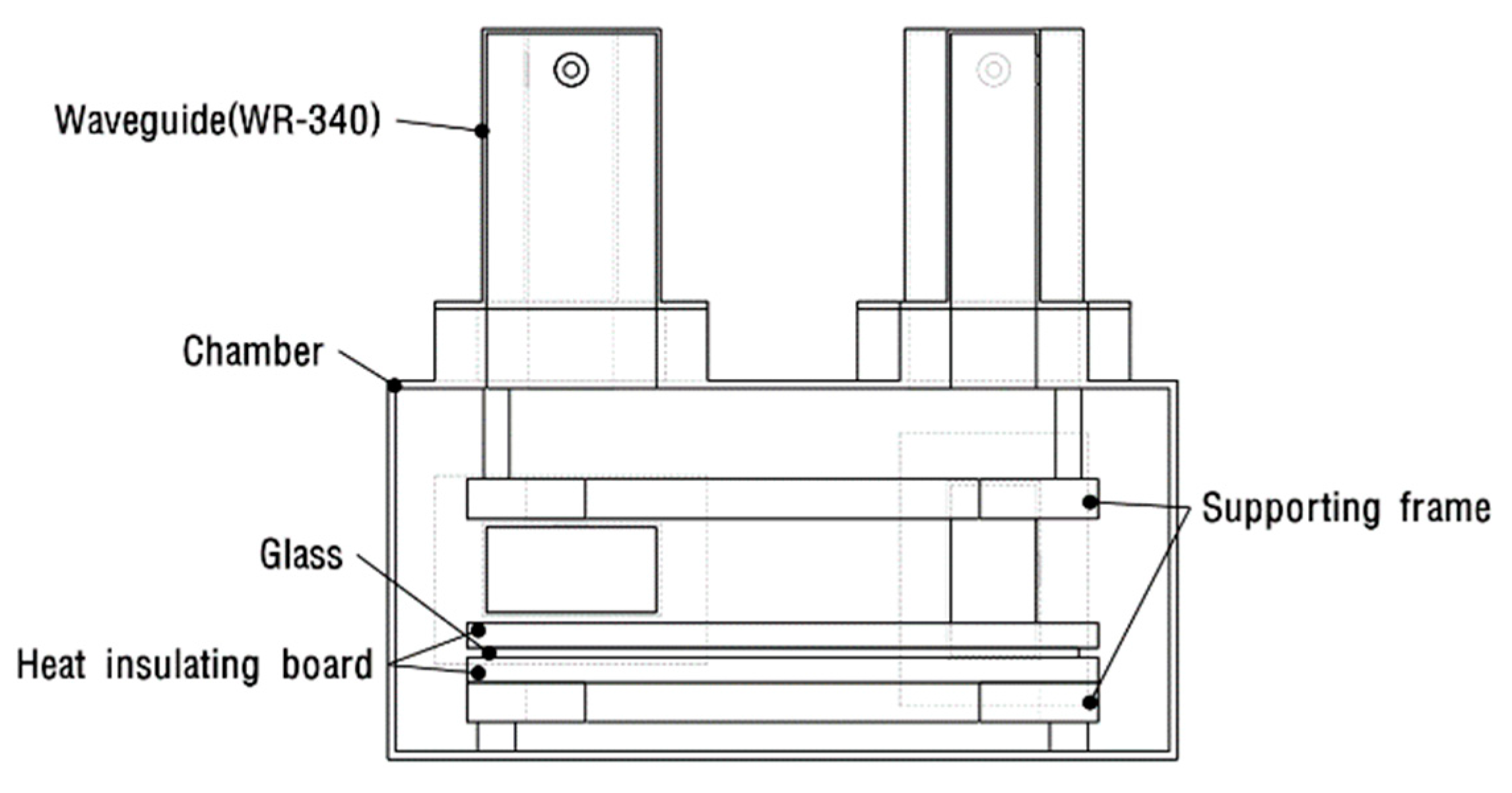
2.2. Microwave System Design
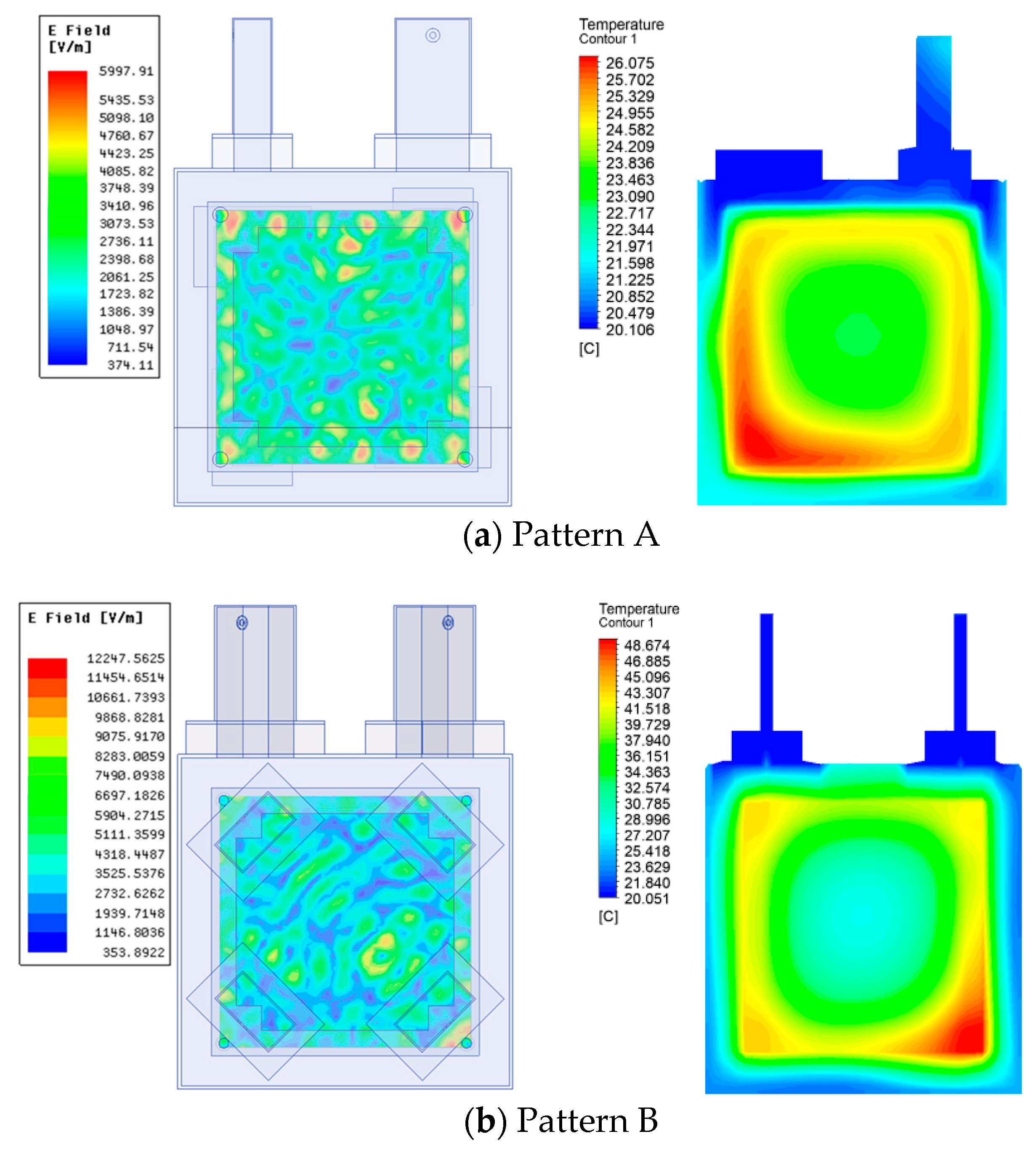
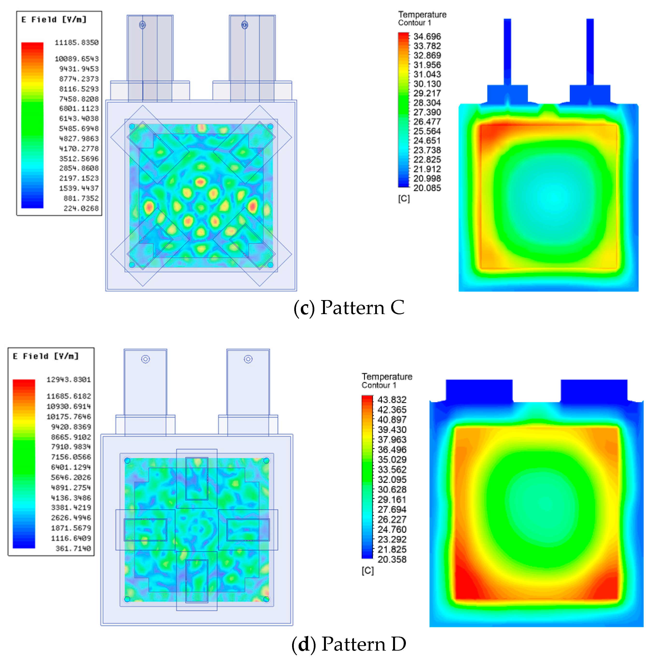
3. Numerical Analysis of Temperature Distribution in the Furnace Chamber
4. Flat-Glass Heating and Edge-Sealing Experiments
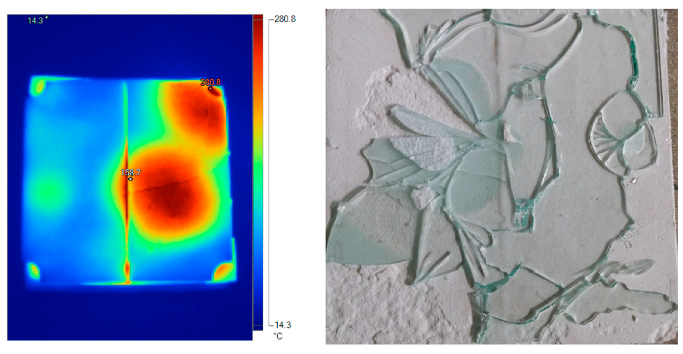
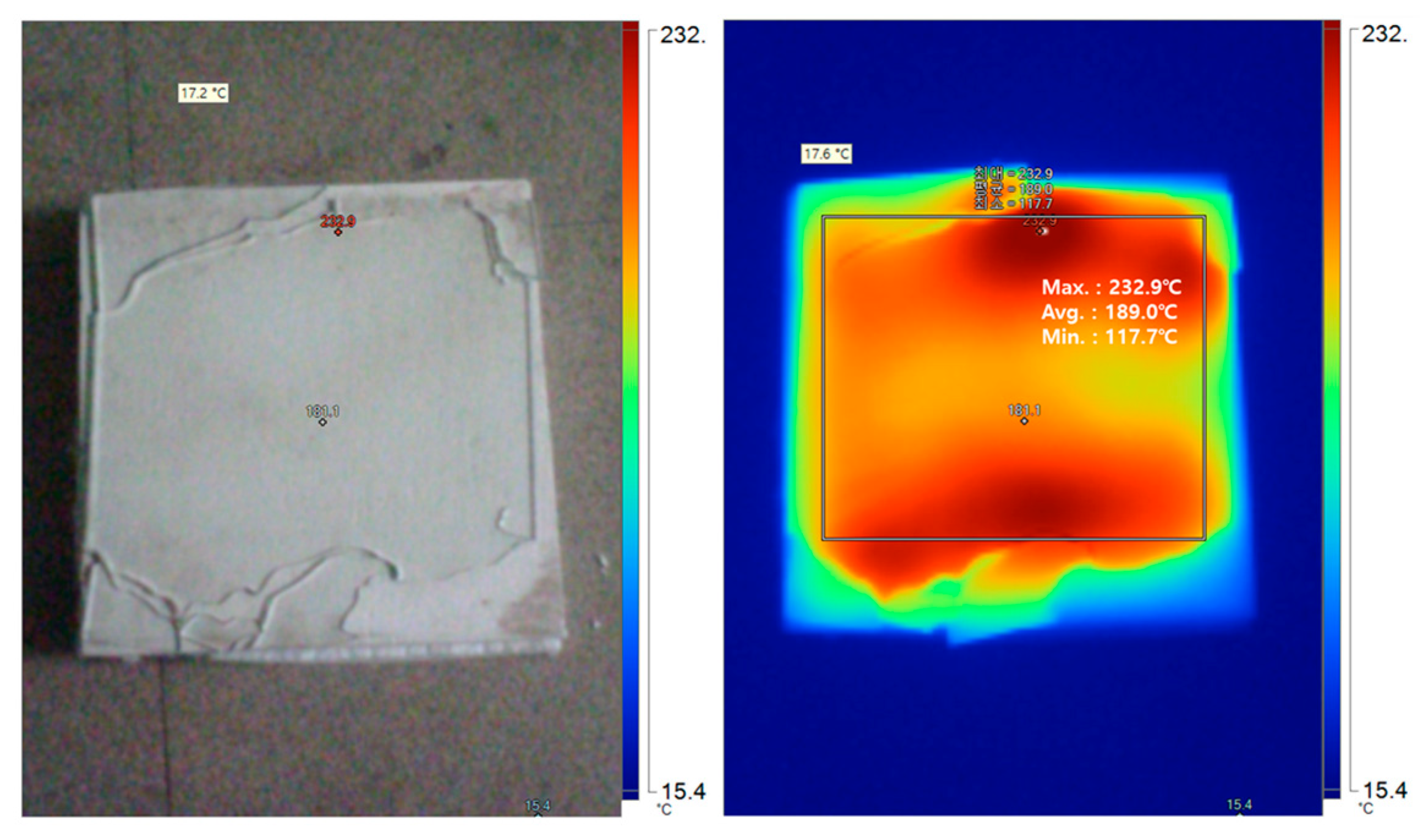
4.1. Basic Flat-Glass Heating Experiments
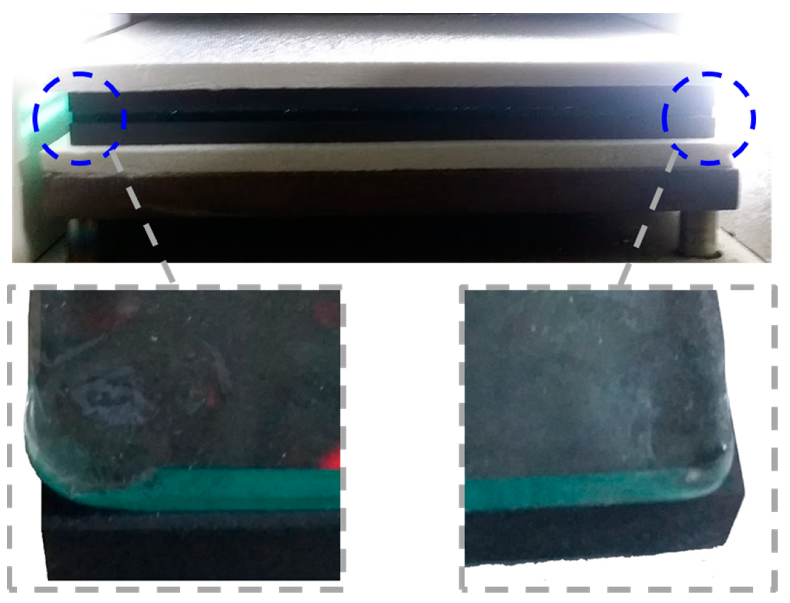
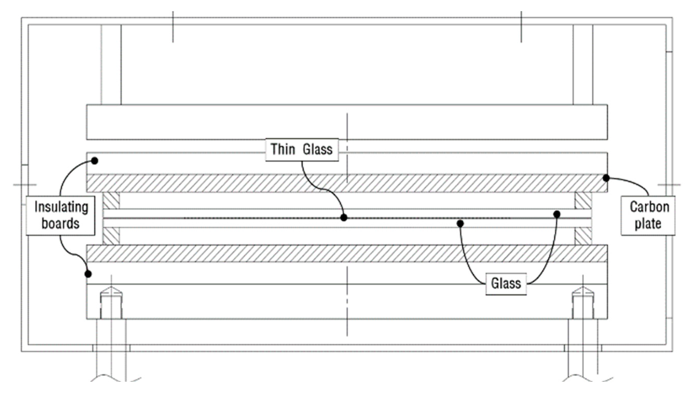
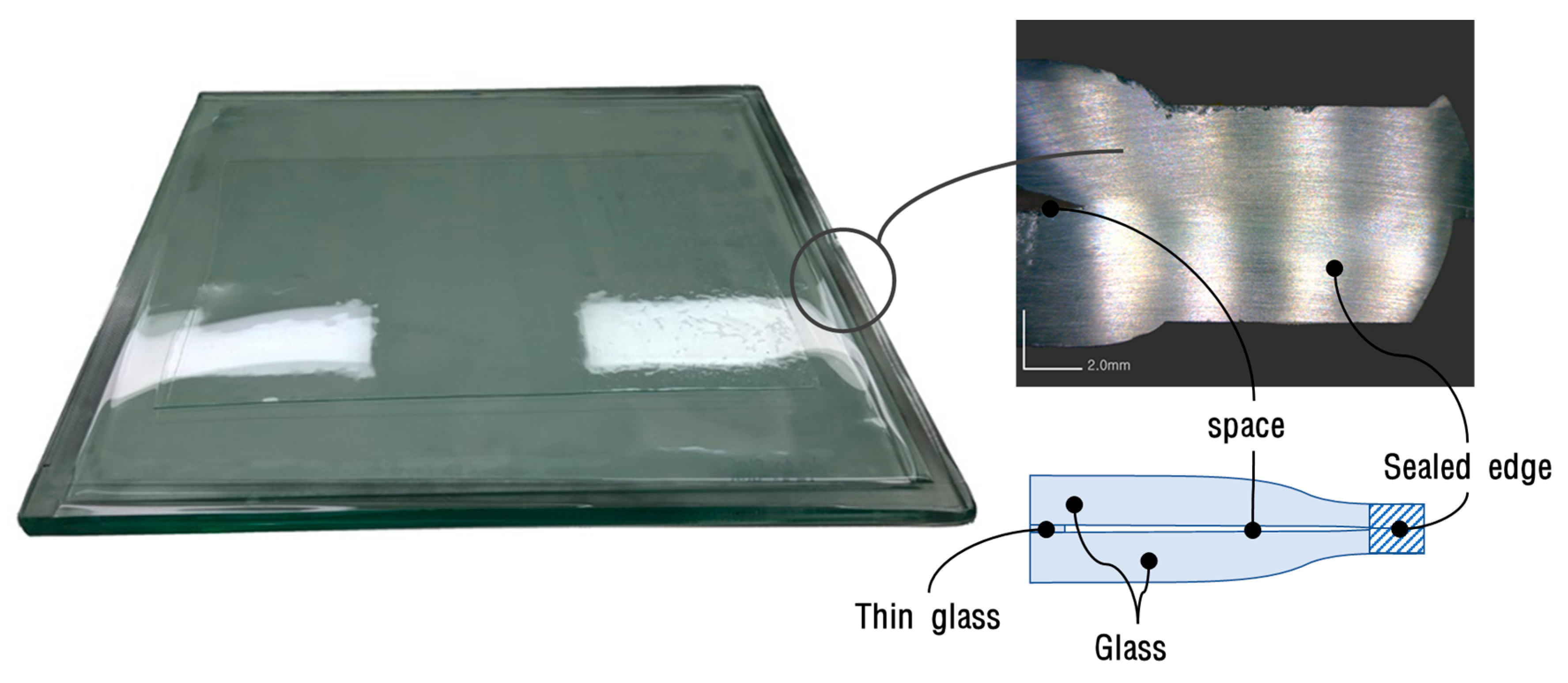
4.2. Glass Edge-Sealing Experiment
5. Conclusions
- We present a novel method for heating and edge-sealing flat glass using microwaves. Simulation involving multiple sources was performed and the appropriate waveguide patterns were derived.
- A 6 kW microwave chamber was then constructed, and heating experiments were performed under various conditions.
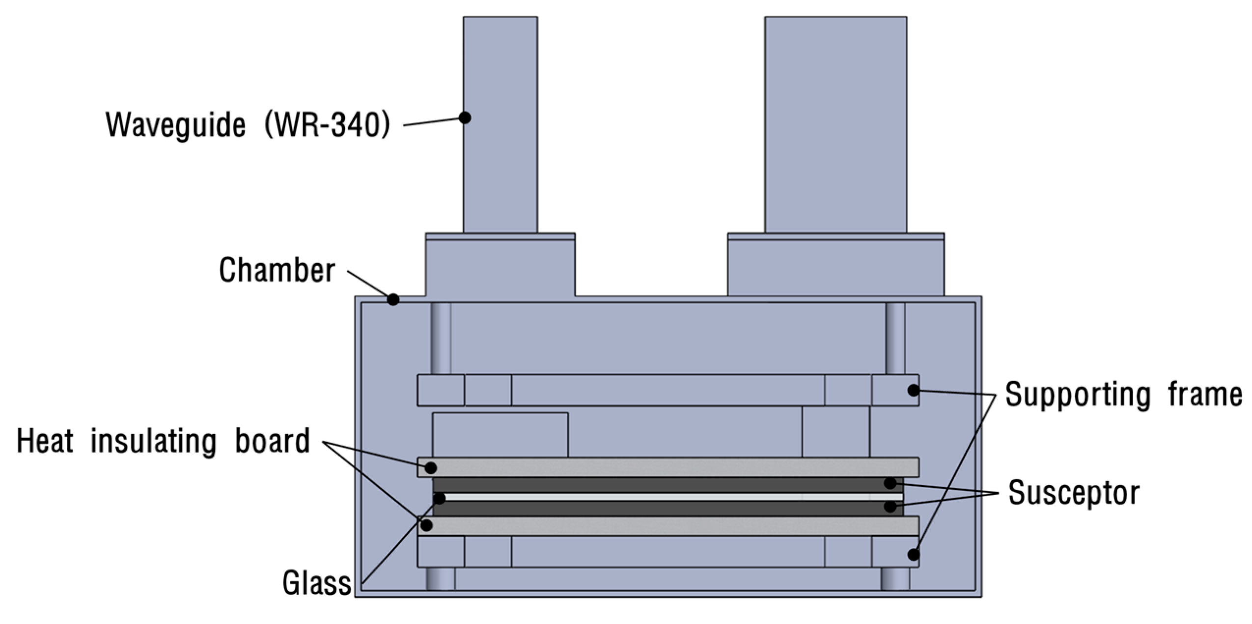
- Glass panes were heated to the glass transition temperature and confirmed that these were sealed by edge pressure, using a system with graphite susceptors. These results indicate the potential for this flat-glass heating and edge-sealing method to be applied in vacuum glazing manufacturing processes.Further research is needed on the edge-sealing process in a vacuum environment.
Author Contributions
Funding
Conflicts of Interest
References
- Cuce, E.; Cuce, P.M. Vacuum glazing for highly insulating windows: Recent developments and future prospects. Renew. Sustain. Energy Rev. 2016, 54, 1345–1357. [Google Scholar] [CrossRef]
- Asphaug, S.K.; Jelle, B.P.; Gullbrekken, L.; Uvsløkk, S. Accelerated ageing and durability of double-glazed sealed insulating window panes and impact on heating demand in buildings. Energy Build. 2016, 116, 395–402. [Google Scholar] [CrossRef]
- Memon, S.; Farukh, F.; Eames, P.; Silberschmidt, V. A new low-temperature hermetic composite edge seal for the fabrication of triple vacuum glazing. Vacuum 2015, 120, 73–82. [Google Scholar] [CrossRef]
- Miao, H.; Shan, X.; Zhang, J.; Sun, J.; Wang, H. Effect of sealing temperature on the sealing edge performance of vacuum glazing. Vacuum 2015, 116, 7–12. [Google Scholar] [CrossRef]
- Zhang, J.; Liu, S.; Zhang, Y.; Miao, H.; Zhang, S.; Zhang, Q. Formation mechanism of sealing edge pores for vacuum glazing using laser brazing technique. Vacuum 2015, 147, 1–7. [Google Scholar] [CrossRef]
- Kim, Y.S.; Jeon, E.S. Using a hydrogen gas torch to seal edges of vacuum glazing panels and related characteristic strength analyses according to sealed edge shapes. Vacuum 2018, 149, 262–269. [Google Scholar] [CrossRef]
- Kim, Y.S.; Jeon, E.S. Establishment of regression model for estimating shape parameters for vacuum-sealed glass panel using design of experiments. Vacuum 2015, 121, 113–119. [Google Scholar] [CrossRef]
- Zhu, H.; He, J.; Hong, T.; Yang, Q.; Wu, Y.; Yang, Y.; Huang, K. A rotary radiation structure for microwave heating uniformity improvement. Appl. Therm. Eng. 2018, 141, 648–658. [Google Scholar] [CrossRef]
- Heddleson, R.A.; Doores, S. Factors affecting microwave heating of foods and microwave induced destruction of foodborne pathogens—A review. Food Prot. 1996, 57, 1025–1037. [Google Scholar] [CrossRef]
- Li, Z.Y.; Wang, R.F.; Kudra, T. Uniformity issue in microwave drying. Dry. Technol. 2011, 29, 652–660. [Google Scholar] [CrossRef]
- Plaza-Gonzalez, P.; Monzo-Cabrera, J.; Catala-Civera, J.M.; Sanchez-Hernandez, D. Effect of Mode-Stirrer Configurations on Dielectric Heating Performance in Multimode Microwave Applicators. IEEE TMTT 2005, 53, 1699–1706. [Google Scholar] [CrossRef]
- Bows, J.R. Variable frequency microwave heating of food. Microw. Power Electromagn. Energy 1999, 34, 227–238. [Google Scholar] [CrossRef] [PubMed]
- Watanabe, S.; Karakawa, M.; Hashimoto, O. Computer simulation of temperature distribution of frozen material heated in a microwave oven. IEEE Trans. Microw. Theory Technol. 2010, 58, 1196–1204. [Google Scholar] [CrossRef]
- Javier, G.S.; de los Reyes, R.; Jara, A.; de los Reyes, E.R. Microwave energy transduction using planar technology. Electron. Lett. 2015, 51, 499–501. [Google Scholar]
- Sun, T. Key models of heat and mass transfer of asphalt mixtures based on microwave heating. Dry. Technol. 2014, 32, 1568–1574. [Google Scholar] [CrossRef]
- Dominguez-Tortajada, E.; Monzo-Cabrera, J.; Diaz-Morcillo, A. Uniform electric field distribution in microwave heating applicators by means of genetic algorithms optimization of dielectric multilayer structures. IEEE Trans. Dielectr. Electr. Insul. 2007, 55, 85–91. [Google Scholar] [CrossRef]
- Hassan, O.A.; Kandil, A.H.; el Bialy, A.M.; Hassaballa, I.A. Improving heating uniformity of pathological tissue specimens inside a domestic microwave oven. J. Microw. Power Electron. Energy 2013, 47, 87–101. [Google Scholar] [CrossRef]
- Yoshikawa, N.; Wang, H.; Mashiko, K.; Taniguchi, S. Microwave heating of soda-lime glass by addition of iron powder. J. Master. Res. 2007, 23, 1564–1569. [Google Scholar] [CrossRef]
- Wu, H.; Grabarnik, S.; Emadi, A.; de Graaf, G.; Wolffenbuttel, R.F. Characterization of thermal cross-talk in a MEMS-based thermopile detector array. J. Micromech. Microeng. 2009, 19, 1–7. [Google Scholar] [CrossRef]
- Fenske, K.; Misra, D. Dielectric Materials at Microwave Frequencies. Appl. Microw. Wirel. 2000, 12, 92–100. [Google Scholar]
- Hill, J.M.; Marchant, T.R. Modelling microwave heating. Appl. Math. Model. 1996, 20, 3–15. [Google Scholar] [CrossRef]
- Aravindan, S.; Krishnamurthy, R. Joining of ceramic composites by microwave heating. Mater. Lett. 1999, 38, 245–249. [Google Scholar] [CrossRef]
- Park, H.-K.; Park, S.-H.; Park, I.-S.; Yang, D.-H.; Cha, S.-H.; Ha, B.-C.; Lee, J.-C. Analysis of Grinding Characteristics of Ceramic (SiC) Materials. J. Korean Soc. Manuf. Process Eng. 2018, 17, 16–22. [Google Scholar] [CrossRef]


© 2019 by the authors. Licensee MDPI, Basel, Switzerland. This article is an open access article distributed under the terms and conditions of the Creative Commons Attribution (CC BY) license (http://creativecommons.org/licenses/by/4.0/).
Share and Cite
Kim, J.K.; Kim, Y.S.; Jeon, E.S. Experimental Study on Flat-Glass Heating and Edge-Sealing Using Multiple Microwave Sources. Energies 2019, 12, 4359. https://doi.org/10.3390/en12224359
Kim JK, Kim YS, Jeon ES. Experimental Study on Flat-Glass Heating and Edge-Sealing Using Multiple Microwave Sources. Energies. 2019; 12(22):4359. https://doi.org/10.3390/en12224359
Chicago/Turabian StyleKim, Jae Kyung, Young Shin Kim, and Euy Sik Jeon. 2019. "Experimental Study on Flat-Glass Heating and Edge-Sealing Using Multiple Microwave Sources" Energies 12, no. 22: 4359. https://doi.org/10.3390/en12224359
APA StyleKim, J. K., Kim, Y. S., & Jeon, E. S. (2019). Experimental Study on Flat-Glass Heating and Edge-Sealing Using Multiple Microwave Sources. Energies, 12(22), 4359. https://doi.org/10.3390/en12224359