Review

Hardware Approach to Mitigate the Effects of Module Mismatch in a Grid-connected Photovoltaic System: A Review

1
Center of Research Excellence in Renewable Energy and Power Systems, King Abdulaziz University, Jeddah 21589, Saudi Arabia
2
Department of Electrical Engineering, Faculty of Engineering, King Abdulaziz University, Rabigh 25732, Saudi Arabia
3
Center of Electrical Energy System, School of Electrical Engineering, Faculty of Engineering, Universiti Teknologi Malaysia, Johor Bahru 81310, Malaysia
4
Faculty of Electrical Engineering, Faculty of Engineering, Universiti Teknikal Malaysia Melaka, Ayer Keroh 71600, Malaysia
5
Department of Electrical and Computer Engineering, Faculty of Engineering, King Abdulaziz University, Jeddah 21589, Saudi Arabia
*
Author to whom correspondence should be addressed.
Energies 2019, 12(22), 4321; https://doi.org/10.3390/en12224321
Submission received: 18 September 2019 / Revised: 31 October 2019 / Accepted: 6 November 2019 / Published: 13 November 2019

Abstract

:
This study reviews the hardware approach to mitigate the effects of module mismatch in a grid-connected photovoltaic (PV) system. Unlike software solutions, i.e. the maximum power tracking algorithm, hardware techniques are well suited to enhance energy yield because of their inherent ability to extract energy from the mismatched module. Despite the extra cost of the additional circuitry, hardware techniques have recently gained popularity because of their long-term financial benefits. Notwithstanding the growing interest in this topic, review papers that provide updates on the technological developments of the three main hardware solutions, namely micro inverter, DC power optimizer, and energy recovery circuits, are lacking. This is in contrast to software solutions, which have had a considerable number of reputable reviews. Thus, a comprehensive review paper is appropriate at this juncture to provide up-to-date information on the latest topologies, highlight their merits/drawbacks, and evaluate their comparative performance.

1. Introduction

The grid-connected photovoltaic (GCPV) system has been widely accepted as the most practical and economical method to harvest energy from the sun [1,2]. Its configuration is very effective; it does not require expensive energy storage components (batteries) to back up the system in the absence of photovoltaic (PV) power. This role is assumed by the electrical grid itself, which can be considered a large energy reservoir that dispatches sufficient power to the load at any instance. For DC-AC conversion, the central inverter is the preferred choice because of its simple installation, low maintenance, and high reliability [3,4,5]. Typically, PV modules are connected in a series-parallel arrangement (array), while the power is fed to the grid via the inverter.
Despite its popularity, the energy yield of the GCPV system is often affected by module mismatch [6,7,8], the most common of which is partial shading. This phenomenon is due to shades that originate from buildings, chimneys, trees, telephone poles, transmission lines, antennas, and other tall structures. Partial shading is also observed when a cloud passes over the modules. Since the PV system is mainly configured using a central inverter, any power mismatch between the modules can cause a disproportionate loss of extracted energy. For example, the authors in [9] estimated that 9% shading of an array can result in system-wide power loss of over 50%. Another source of mismatch is irregularities in module surfaces. This can be due to defects that occur during manufacturing. The irregularity can also be a result of cracks and uneven aging of modules within the array. Other possible sources of the mismatch are bird droppings, animal remains, vegetation growth (especially moss and fungi), and leaves that drop on the module.
Under normal conditions, the P-V characteristic curve exhibits a standard shape, i.e., with a single (unique) maximum power point (MPP). As the MPP is unique, it can easily be located by conventional maximum power point tracker (MPPT) algorithms, such as perturb and observe (P&O), incremental conductance (IC), and hill climbing (HC). In the case of a module mismatch, the high current from the “good” modules flows into the “affected” ones, forcing the latter to behave as a current sink element [10,11,12,13,14,15,16]. The current rush creates a hotspot that results in heating. To protect the affected module from being damaged, bypass diodes are installed to divert the excessive current. From a P-V characteristic perspective, the bypassing action results in the transformation of the curve from a single to multiple peak (multi-modal).
The main challenge of the software solution, thereafter, is to ensure that the MPPT can consistently track the correct MPP in the multi-modal P-V curve. The P&O, IC, or HC is not suited to handle this condition because it cannot differentiate between local and global peaks [17]. At most times, it traps at the local peak, causing considerable power losses [9,10,12]. There have been recent proposals to solve this problem using sophisticated soft computing techniques. The idea is for the MPPT to perform a point-by-point search of the P-V curve until the MPP is located. Among the well-known methods are artificial neural networks (ANN), genetic algorithms (GA), particle swarm optimization (PSO), and differential evolution [9,17,18,19,20]. Generally, these algorithms are able to track global peaks under any shading condition, provided that the voltage step during the search is sufficiently small. This requirement, however, results in slow convergence. It is important to note that because of the short-circuiting (of the bypass diode), the affected module cannot contribute any power to the string. Thus, no matter how much improvement is made to the MPPT algorithm, the output power is always lower than can possibly be extracted from the system.
One way to overcome this drawback is by hardware intervention. Numerous initiatives are made on the basis of this idea; they are categorized into the following three main groups: micro inverter, DC optimizer (DCO), and energy recovery circuits. Despite the large number of published work on hardware mitigation techniques, a comprehensive review on this subject is lacking. For example, although there are a number of review articles on micro inverters, [4,21,22,23,24], they are specifically focused on the former and did not cover other categories. Recently, a detailed review paper (which includes performance evaluation) was written on mismatch mitigation using hardware solutions [25]. However, despite similarity in the title, the authors were mainly concerned with 1) the bypass techniques using a diode/transistor and 2) power electronics methods, which are similar to energy recovery circuits. Unfortunately, they omitted two of the most important mitigation techniques that are quickly gaining acceptance in the marketplace, namely, the micro-inverter and the DCO. Furthermore, it must be noted that the bypass and energy recovery methods are mainly based on the central MPPT configuration. On the other hand, the micro inverter and DCO employ the distributed MPPT concept, which maximize the energy extraction from individual modules. With this distinction, the present work can be considered a compliment to the review carried out in [25].
Thus, it is appropriate at this juncture to provide a review on the three main groups mentioned in the hardware approach. This paper will mainly elaborate on the evolution and development of the major topologies, their merits/drawbacks, as well as a comparative evaluation of their performances. The review will provide up-to-date information that can be useful for PV designers when deciding if these solutions can be applied to their respective systems. However, this study will not provide a comparison between specific brands (or products), as the number of new models for micro inverters and DCOs entering the market is growing by the day. Rather, the focus is on understanding the concepts and operation of the main circuits. For the benefit of readers who are new to this field, a brief introduction to MPPT, the module mismatch concept, and the inadequacy of software solutions are also provided.
The paper is organized as follows: Section 2 provides a brief overview of the partial shading on PV system and the role of the bypass diode. The formation of multiple peak P-V curves and failure of the conventional MPPT to track the global peak is explained. Section 3 justifies the need to introduce the hardware solution to mitigate the effect of partial shading. This is followed by a detailed review on the main circuits/topologies/techniques discussed in the literature, namely the micro-inverter, DCO, and the energy recovery circuit. They are arranged in Section 4, Section 5 and Section 6, respectively. Section 7 provides a comparative evaluation of these three approaches. Their performance is categorized in terms of component count/lifetime and efficiency. Furthermore, certain aspects on the practical implementation are highlighted. Finally, a comprehensive list of references is provided to assist readers who wish to probe the subject further.

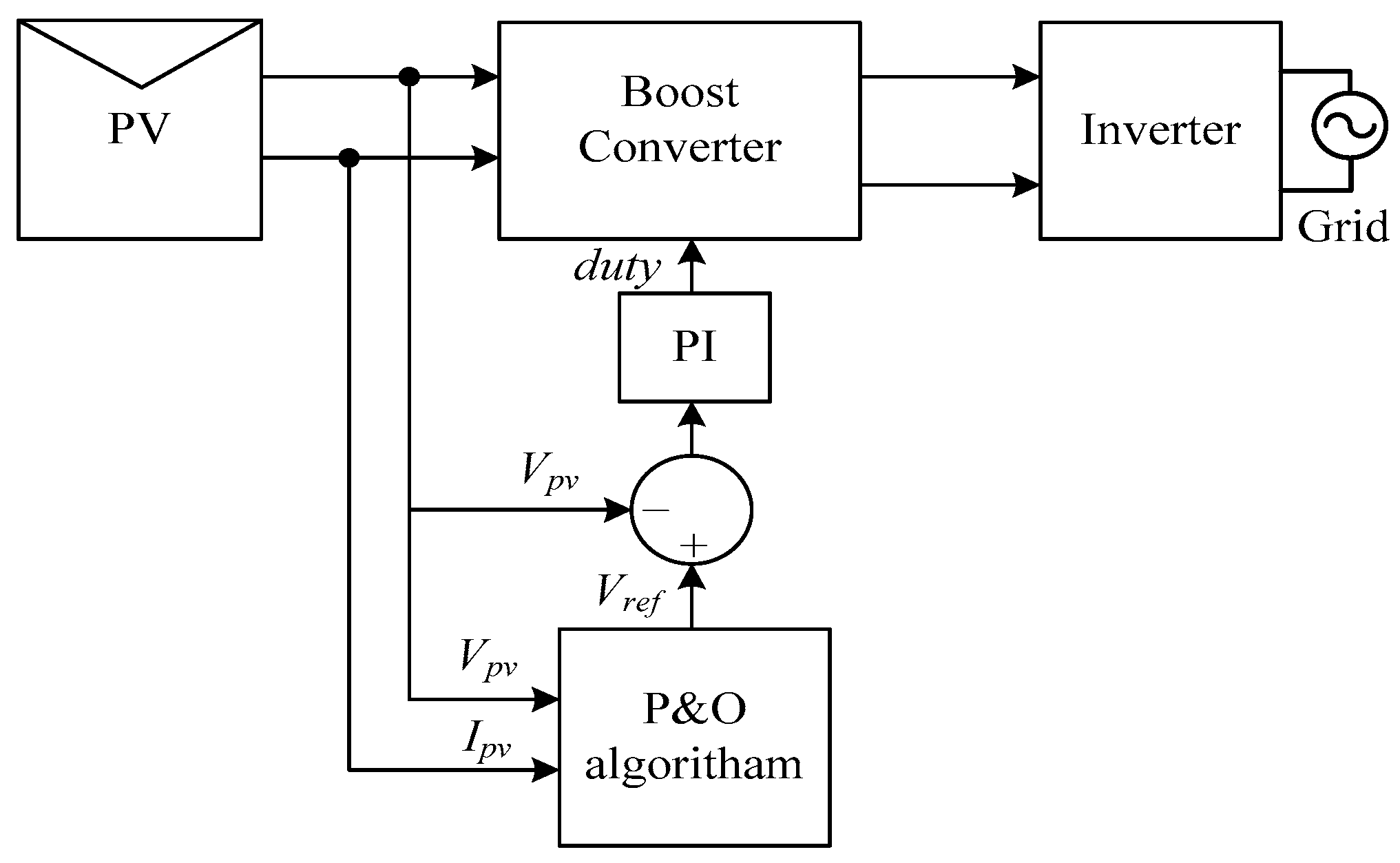
2. Maximum Power Point Tracker (MPPT)

As the position of the MPP on the P-V curve varies with irradiance (G) and temperature (T), the MPPT is required to ensure that maximum power is extracted from the module at any environmental condition. Figure 1 shows the general block diagram of the MPPT in the GCPV environment [26,27]. The current and voltage of the array are sensed; with the use of this information, the present value of power (Pn) is computed. Then, the MPPT algorithm is executed; based on the difference between the computed and the measured MPP, the duty cycle of the boost converter is adjusted using the proportional-integral controller [27,28].

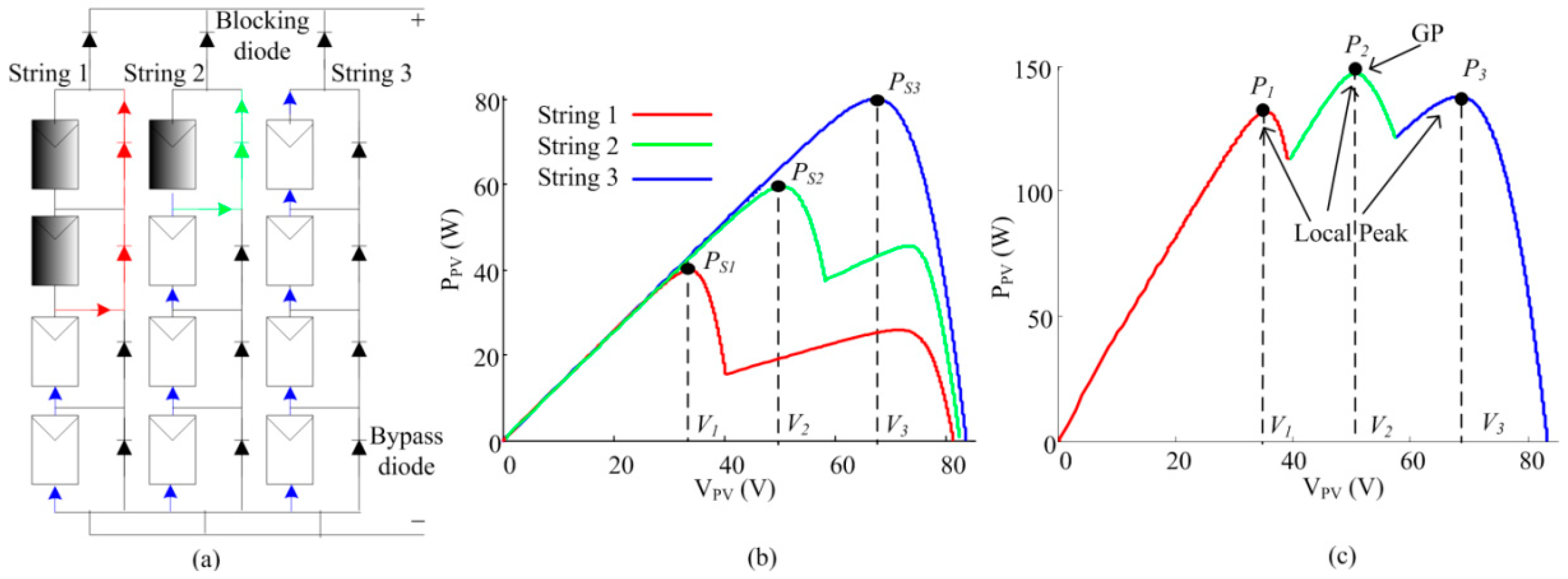
2.1. Bypass Diode and Multiple-peak P-V Curve

One of the most common causes of module mismatch is partial shading. The behavior of a PV system under partial shading is illustrated in Figure 2a [29]. The array is made of three identical strings, with four modules per string. For String 3, all modules are subjected to full (uniform) irradiance, i.e., G = 1000 W/m2. As expected, all the bypass diodes are reverse-biased; thus, the string current flows normally through all modules. This results in a single-modal P-V curve (with a unique peak, Ps3), as shown by the blue trace in Figure 2b. For String 2, one of the modules is deliberately shaded at half of the full irradiance, i.e., G = 500 W/m2. Here, the voltage differential between the shaded (G = 500 W/m2) and non-shaded (G = 1000 W/m2) modules activates the bypass diode of the former. Consequently, the shaded module is short-circuited, resulting in a P-V curve with two peaks. For String 1, two modules are shaded at half irradiance; the corresponding P-V curve also exhibits two peaks. Figure 2c shows the resultant multi-modal curve that is obtained by the superposition of the three waveforms in Figure 2b. There are three peaks, namely, P1, P2, and P3. The highest (P2) is considered as the global maximum power point (GMPP).
It must be noted that although the scenario given in this example is for partial shading, similar observations can be made to other mismatch conditions, for example, module cracks and irregularities [30,31]. In such a case, the affected modules force the bypass diodes to behave in the same way as they do for the partially shaded string.

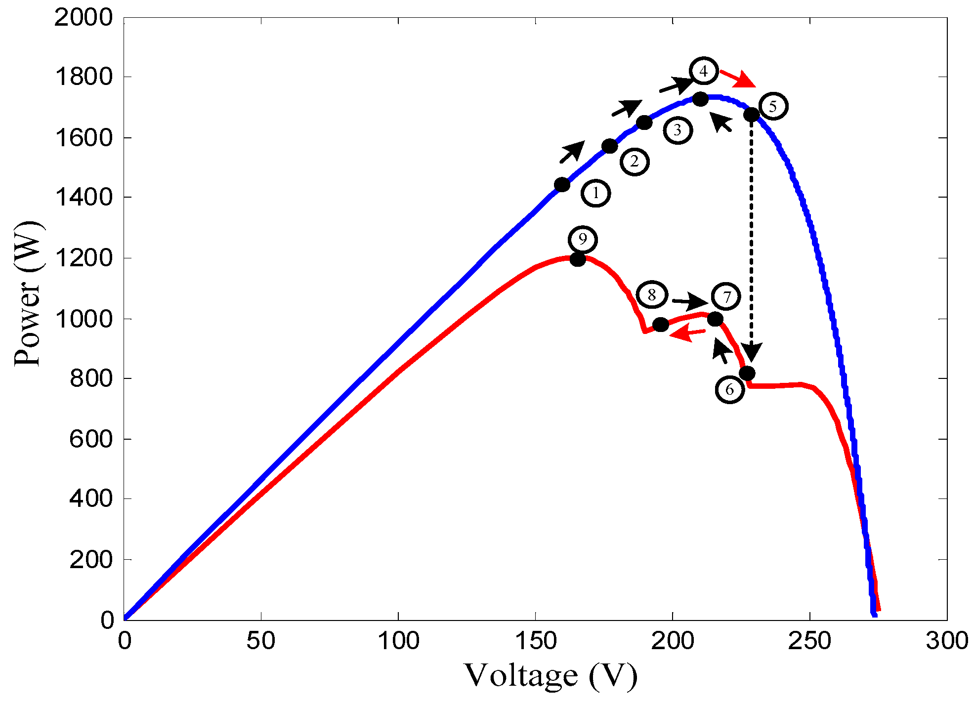
2.2. Failure of the MPTT to Track the Global Peak

Among the conventional MPPTs, P&O is widely used because of its simplicity and fast response. The tracking process of P&O during uniform irradiance is indicated by the blue trace of the P-V curve, as shown in Figure 3 [15]. Starting from Point 1, the operating point gradually climbs uphill. In this duration, the difference between Pn and Pn1 is positive; the direction of perturbation is maintained, and the climb continues until Point 3. In the next iteration, the operating point exceeds the MPP (Point 4) and goes downhill toward Point 5. As the algorithm detects a negative power difference, it reverses the perturbation direction, and the operating point moves back to Point 3. In subsequent iterations, the operating point oscillates forward and backward around Point 3, the MPP, and Point 5.
When module mismatch occurs, the single peak P-V curve is transformed to multiple peak, as shown by the red trace in Figure 3 [32,33,34]. Assuming that the operating point is presently at Point 5, the module mismatch causes the power to drop suddenly to Point 6 (on the red trace). From there, the P&O climbs to a local peak at Point 7. In the next iteration, the operating goes downhill toward Point 8. As anticipated, it oscillates around Points 6, 7, and 8 and could not leave the vicinity of this (local) peak. Since the algorithm is not aware of the existence of the true global peak (i.e. Point 9), it assumes the former as global. The difference between the two is the amount of power lost during the iteration.

2.3. Advanced Software Search Methods

To correctly track the global peak during module mismatch, the MPPT must be able to discriminate between the local and global maxima points. This is not trivial because in the real situation, the algorithm does not know if the present MPP is the global peak or not. The authors in [15] modified the P&O by dividing the process into two parts: the global and local tracking modes. The former is used to bring the operating point to the vicinity of the global peak; once this is done, a conventional P&O is designed to maintain the operating point at the MPP. To avoid scanning the entire voltage span, the algorithm assumes that the peaks occur at multiples of 80% of the open circuit voltage Voc. As shown in Figure 3, the module mismatch takes place when a sudden change in power (∆P) is detected. If the ∆P is larger than a threshold value ∆Pcrit, it assumes that the condition occurs and the algorithm activates the global mode. It searches the vicinity of the multiple of 0.8 Voc and stores the values of all detected peaks (local and global) over the entire voltage span. Then, these peaks are compared; the one with the highest value is considered to be the vicinity at which the global peak is located. Once the approximate location of the global peak is determined, the algorithm switches over to the local mode, in which the P&O maintains the MPP until a new module mismatch condition is detected.
The above-mentioned search method is very effective and has been used by [35,36] for hill climbing and incremental conductance, respectively. The same concept is used to accelerate the search using soft computing methods, such as in [37,38,39].

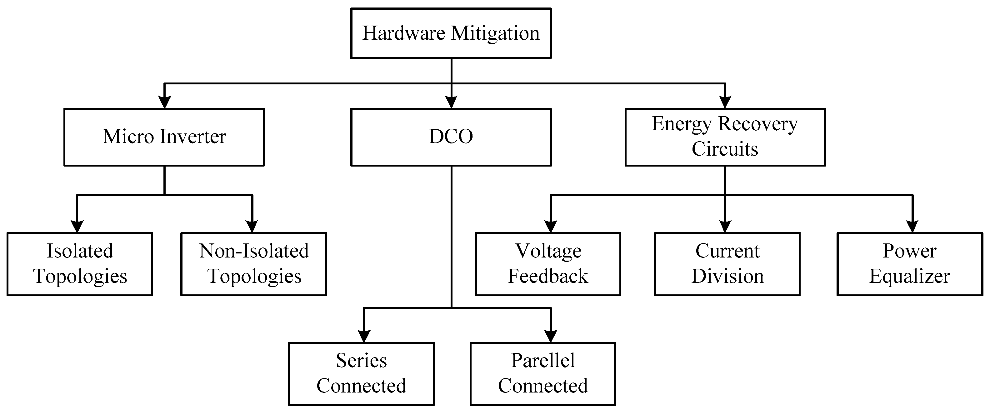
3. Mitigation Using Hardware Solutions
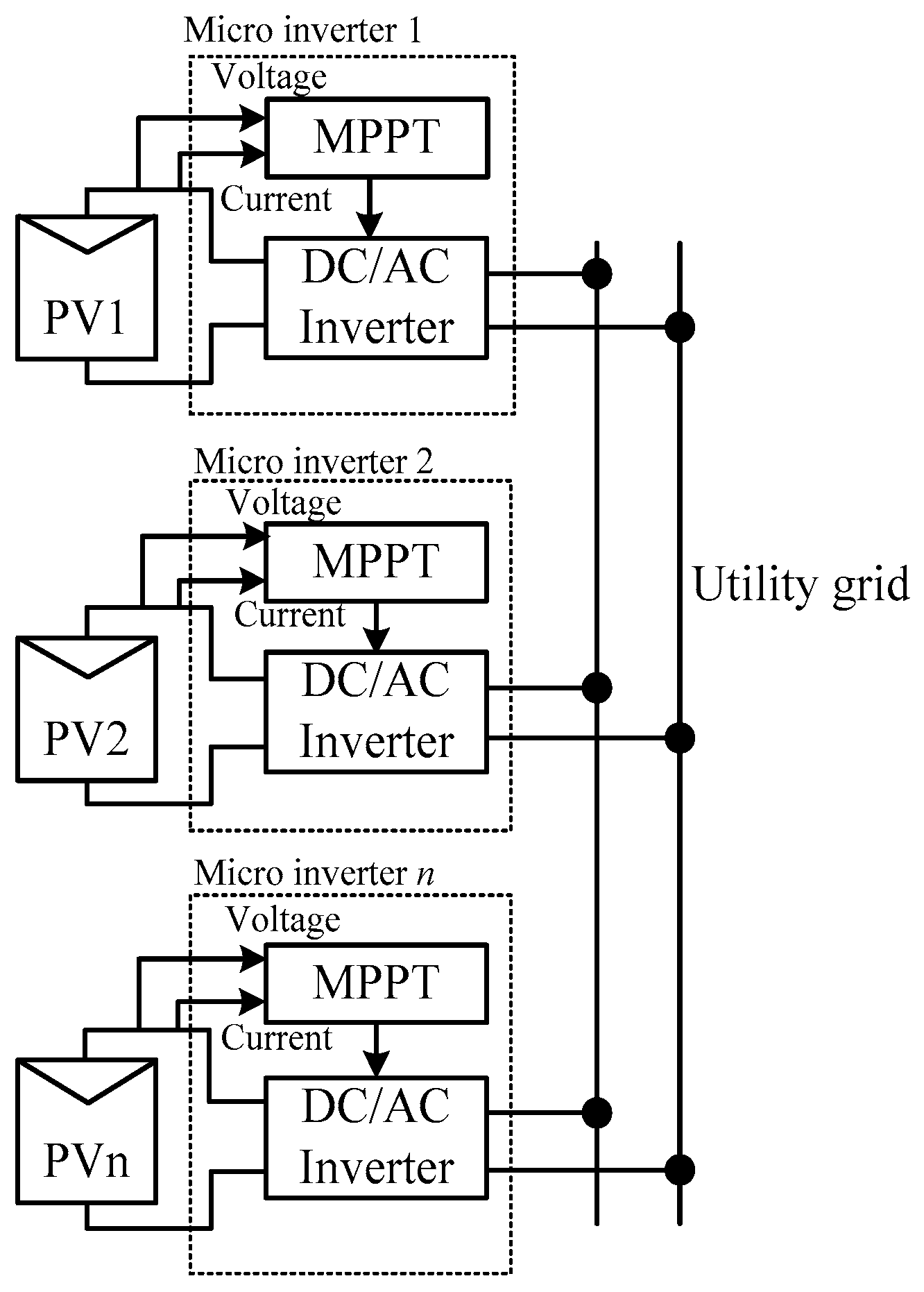
Despite the effectiveness of the advanced search, it has one major drawback: as long as the bypass diode is activated, there are certain amounts of energy in the shaded modules that would not be recoverable. This is reflected by the lower MPP value on the multi-modal P-V curve. In other words, even if the MPPT successfully tracks the global peak, it could not physically extract the energy from the shaded modules. This limitation is inherent and can only be addressed by using the hardware solution. Hardware techniques have recently gained popularity despite the additional retrofitting cost [40,41,42,43]. Three approaches are effectively used: micro inverter, DC power optimizer (DCO), and energy recovery circuits. Figure 4 shows the family-tree chart that illustrates the relationship between the different techniques employed in these approaches.

4. Micro Inverters

A micro inverter is a (small) dedicated DC-AC converter, fitted permanently under the module. The inverter normally has a power rating approximately equal to the module itself and its output is connected directly to the AC grid. Each device is equipped with its own MPPT, allowing its output to be independently controlled. Thus, in essence, the micro inverter simply takes all the functions of a string inverter and miniaturizes them to the module (instead of string) level. A typical interconnection for a micro inverter-based PV system is shown in Figure 5 [23,44,45,46,47,48,49]. This configuration is very attractive for a low voltage grid; thus, it is particularly suitable to the BIPV application.

4.1. Architecture of Micro Inverters

The main advantage of a micro inverter is that it allows each module to inject its power directly into the grid, regardless of how other modules in the system are performing [50,51]. This is because the inverters are not connected together as a string. For example, in Figure 3, if PV1 is shaded, other modules are not affected by the shading because these modules are not connected to one another. Consequently, the energy from PV1 can be fully harvested (using its own MPPT) and delivered to the grid. As each module can be considered an independent power generation unit, the possibility of a hotspot vanishes. Moreover, there is no need to install string diodes, thus avoiding additional conduction losses. Another unique feature of the micro inverter is its flexible interconnection to the grid. As the modules do not need to be connected in a certain configuration (for example, series-parallel), the system size can be progressively increased. Theoretically, this allows the system owner to expand its power generation capacity in tandem with his/her economic status. Nowadays, several manufacturers integrate the micro inverter into the module, and these are sold in the market as a single package [52,53].
As the module voltage is normally much lower (less than 50 Vdc) than the grid voltage (120 or 230 Vac), a step-up mechanism is required. This is achieved by either using a high-frequency transformer or by installing a front-end DC-DC boost converter. Based on this classification, micro inverters can be broadly divided into two categories: isolated and non-isolated. The isolated type is preferred because of its higher power quality output. In addition, it has an inherent safety feature because of the galvanic isolation provided by the transformer [54,55,56]. On the other hand, the non-isolated type is more compact (and thus has a smaller footprint) because of the absence of an isolation transformer.

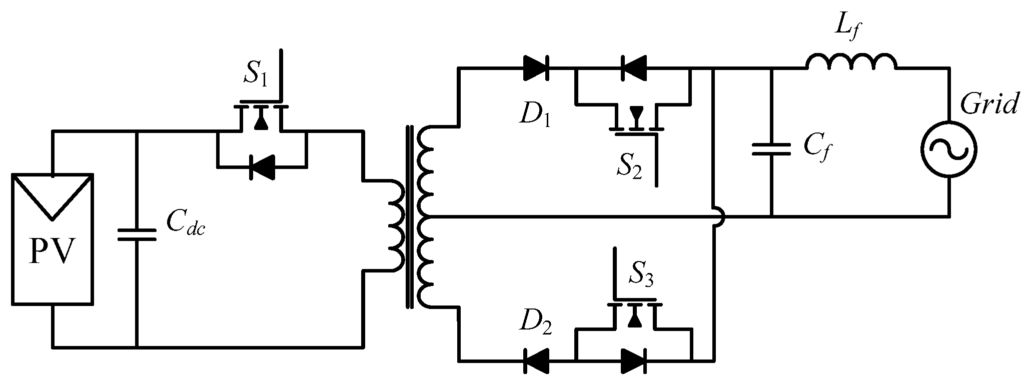
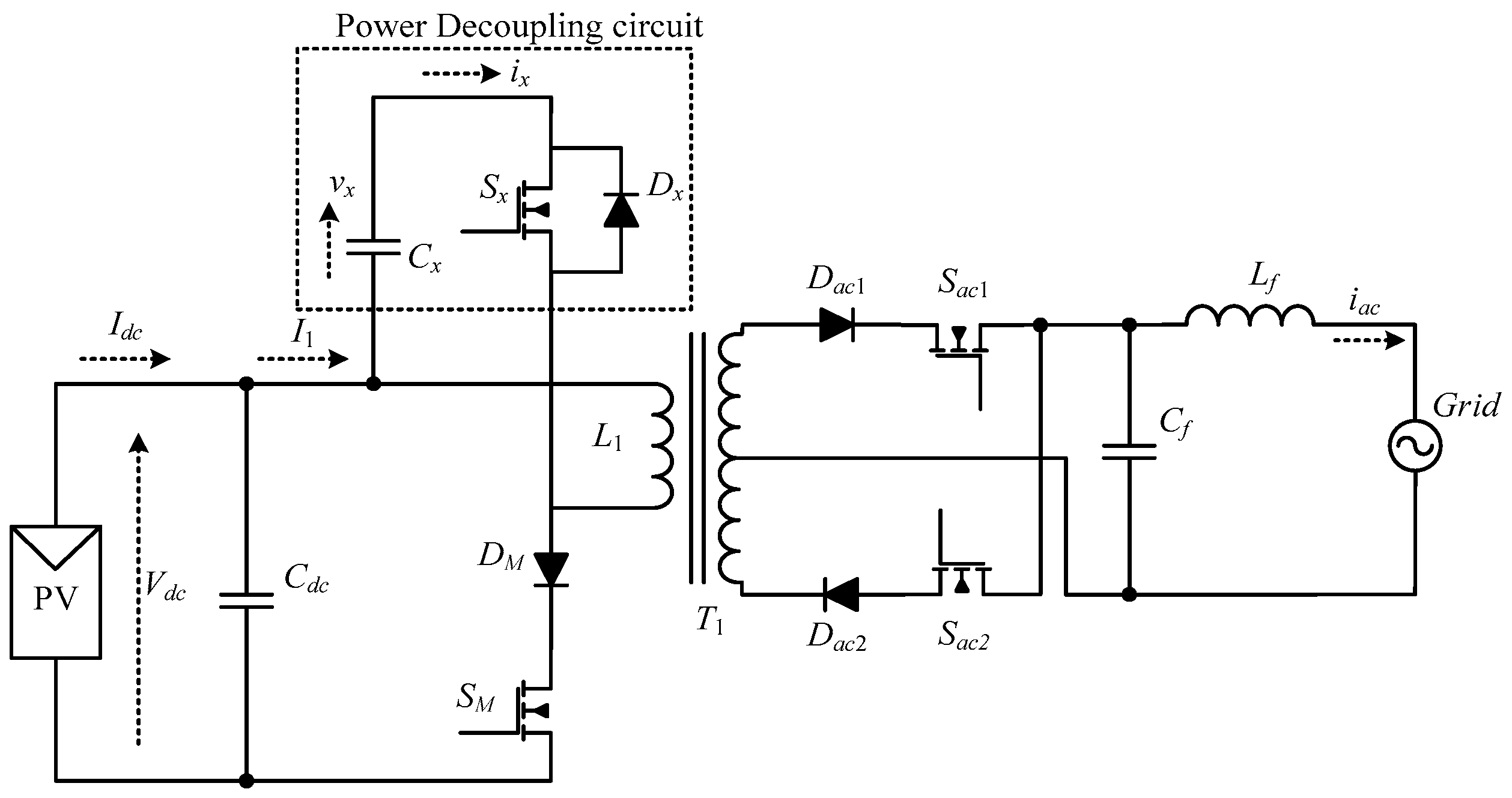
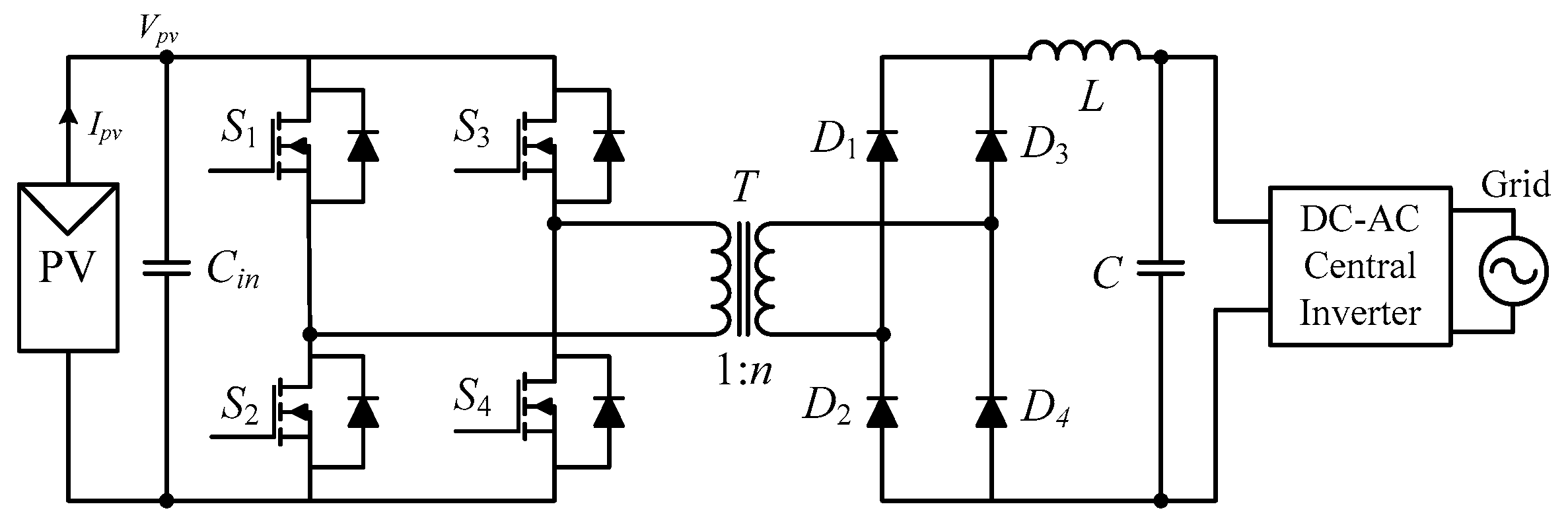
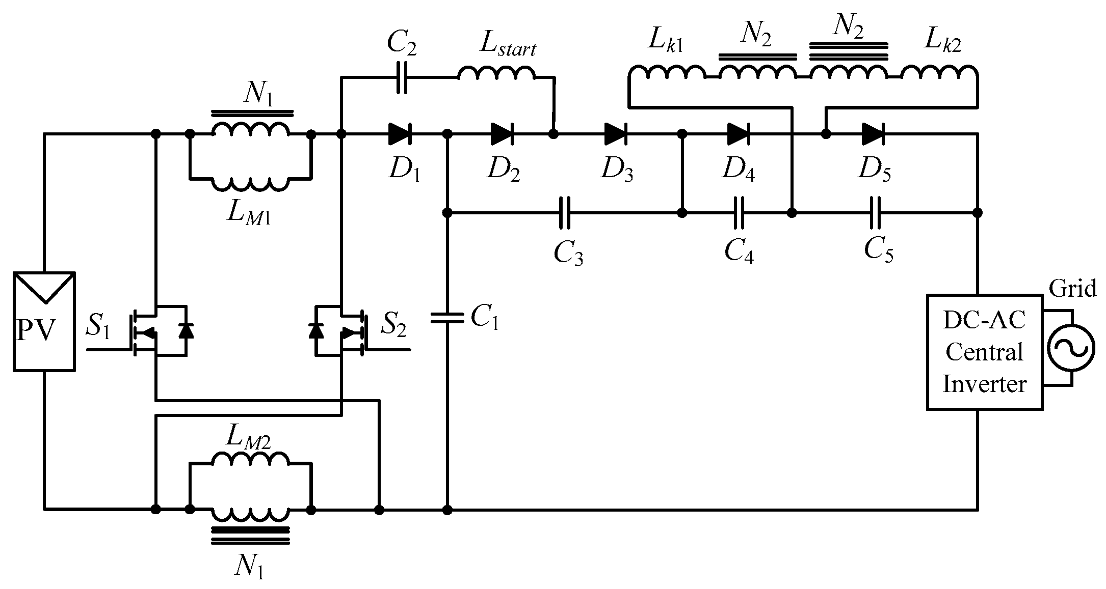
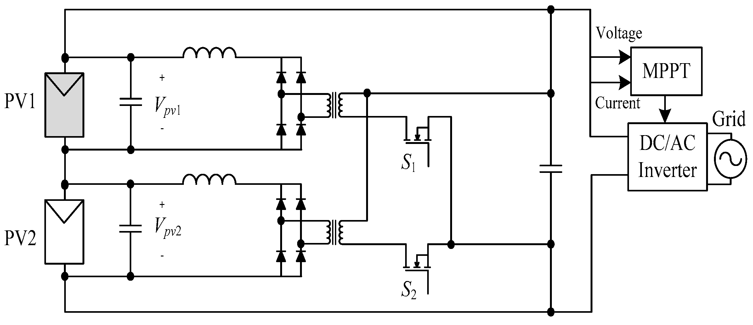
4.1.1. Isolated Topologies

The most popular isolated micro inverter is based on the flyback topology. Its basic circuit is shown in Figure 6. It consists of three MOSFETs (i.e., S1, S2, S3), two diodes, and a high-frequency flyback transformer [48,56,57]. Owing to the individual MPPT control, the AC current can be independently injected to the grid. Several flyback circuits can also be paralleled without the need for a specific current-sharing controller [58]. The MPPT (its circuit is not shown for brevity) is accomplished by adjusting the duty cycles of S1. This switch modulates the DC current (drawn from the module) into a folded sinusoidal waveform. At the secondary, it unfolds the waveform by using S2 and S3. Finally, the inverter injects the AC current into the grid via an output low-pass filter (Lf and Cf) [54]. Besides stepping up the voltage, the transformer decouples the module from the grid, thus avoiding electrical accidents. The typically reported efficiency of this type of micro inverter is approximately 89–95% (at 250–300 W) [22,59,60]. The bulk of power losses originate from the isolation transformer.
Figure 7 shows an improved flyback using the interleaved technique [61]. The interleave effect is achieved by duplicating the converter at the primary side. The modulated sinusoidal waveform is constructed by SP1 (phase 1) and SP2 (phase 2). Then, the voltage is stepped up and transferred to the secondary, where an H-bridge inverter (SP2SP2) unfolds the rectified waveform. Other unfolding circuits, for example, half-bridge, can also be used, but the H-bridge is preferable, as it reduces voltage stress across the secondary switches. The high frequency component (of the modulated sinusoidal waveform) is filtered prior to grid connection. Although the topology is more complex compared with that of the basic flyback, it reduces the voltage and current ratings of the switches. Moreover, because of the interleaving mechanism, the input voltage ripple, the secondary current ripple, and the pseudo DC-link voltage ripple are reduced.
Another approach to improve flyback micro inverters is to use the power decoupling technique [58,59]. An auxiliary (external) circuitry is added for this purpose, as shown in Figure 8 [58]. The same function can also be achieved by S2 and an additional transformer at the primary side, as illustrated in Figure 9 [59]. In the latter topology, the transformer leakage energy is utilized by the decoupling circuit itself; thus, there is no need for additional dissipative circuits. This leads to reduced power losses and improved efficiency. The decoupling allows the removal of the low-frequency power pulsation that appears at the input. Consequently, the capacitance on the DC side can be made much smaller. This allows film or ceramic capacitors to be used instead of the electrolytic type. Using the former, a longer lifetime of the inverter under high-temperature conditions is expected. The circuit is also smaller in volume and lightweight, and can be built at a lower cost.

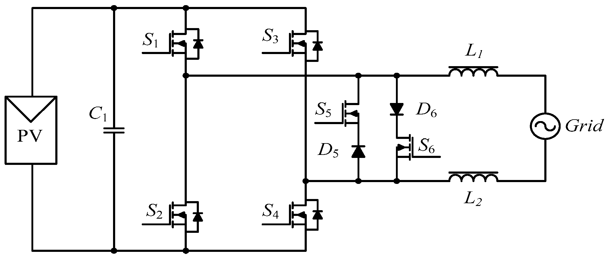
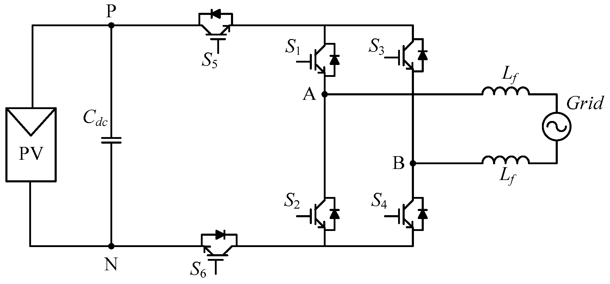
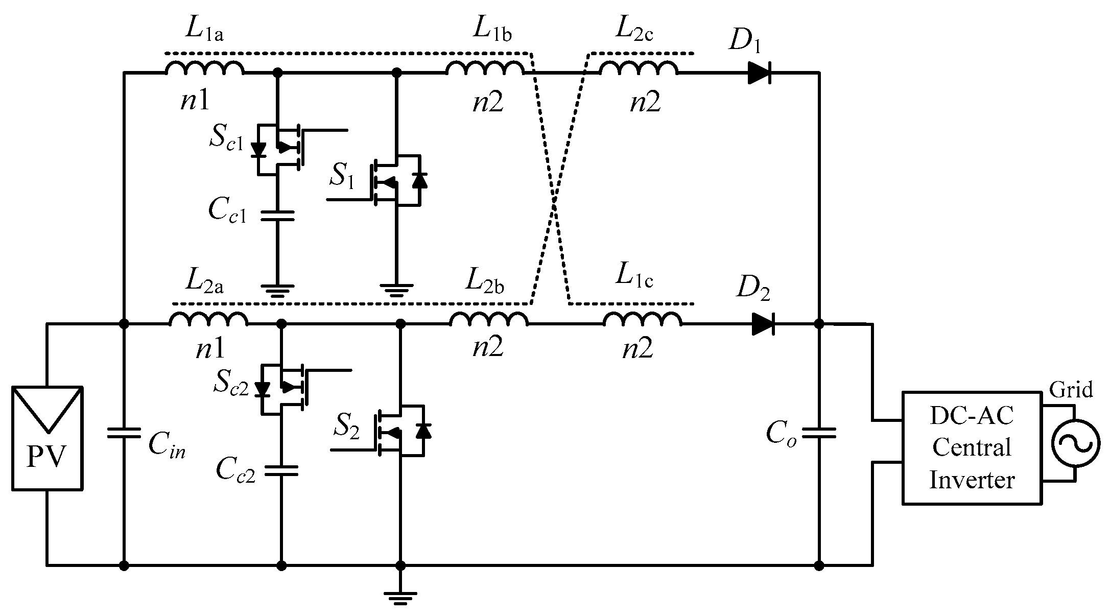
4.1.2. Non-isolated Topology

The switching losses of the flyback circuit and its large transformer leakage inductance make the overall system efficiency drops. The presence of the transformer also increases the cost per watt. To improve efficiency and lower the cost, transformerless (non-isolated) micro inverter topologies are developed [62,63,64]. Despite these merits, the absence of galvanic isolation results in common-mode voltage generation. This causes the leakage current to flow through the parasitic capacitor, inducing power losses, electromagnetic interference, safety problems, and a reduction in the quality of the output current [56].
One technique to minimise the leakage current is implementing the disconnection scheme on the AC side. A popular topology that uses this technique is the highly efficient and reliable concept (HERIC) inverter [65]. As shown in Figure 10, one of the two sets of the switches (i.e., S5/D5 or S6/D6) is used to decouple the module from the grid during the free-wheeling period. This action reduces the common-mode voltage. A peak efficiency of 97.8% is reported for a commercial IGBT-based HERIC inverter [66]. This efficiency is increased to 99% using SiC-JFET switches [67]. In [68], a bidirectional IGBT switch is used to replace the two sets of switches in order to generate zero-state voltage. The circuit is illustrated in Figure 11. The switch is clamped to the midpoint of the capacitor using an extra diode to fix the PV voltage during the zero state. However, because of the conduction losses of the diodes, a lower efficiency is reported. Another topology to reduce leakage current is shown in Figure 12 [69]. In this circuit, the disconnection of the module is done on the input side by adding two auxiliary switches (S5 and S6) to the full bridge.

4.2. Drawbacks of Micro Inverters

Despite its effectiveness, the micro inverter exhibits several shortcomings. During operation (with or without module mismatch), the micro inverter continuously conducts the full load current, resulting in high conduction losses [70]. For the isolated topology, the utilization of a high-frequency transformer is not desirable because of its increased size and losses. Although these losses can be resolved using the transformerless topology, the latter suffers from leakage current and a common-mode voltage problem. This needs to be addressed using the complicated switching technique, as highlighted above. In addition, the non-isolated micro inverter requires a front-end DC-DC converter to boost the module voltage for grid connectivity. Cascading these two converters (the inverter and the front-end DC-DC) significantly reduces overall efficiency.

5. DC Power Optimizers (DCOs)

The DCO, sometimes known as the power optimizer, is another solution for module mismatch using the hardware approach. The DCO is basically a special DC-DC converter, installed underneath individual modules. As such, it can be considered module-level power optimization. Similar to the micro inverter, each DCO has its own dedicated MPPT to maximize output power extraction [6,49,71]. In a typical installation, a number of DCO devices are configured in series before being connected to the central inverter. This is in contrast to the case of the micro inverter, whose output is directly connected to the grid. Positioning the central inverter in between the array and the grid results in numerous advantages, as mentioned in the Introduction [70,72,73]. The conventional non-isolated DC-DC converter, such as buck, boost, and buck-boost is commonly used as the main building block of the DCO [70,72,74,75,76].

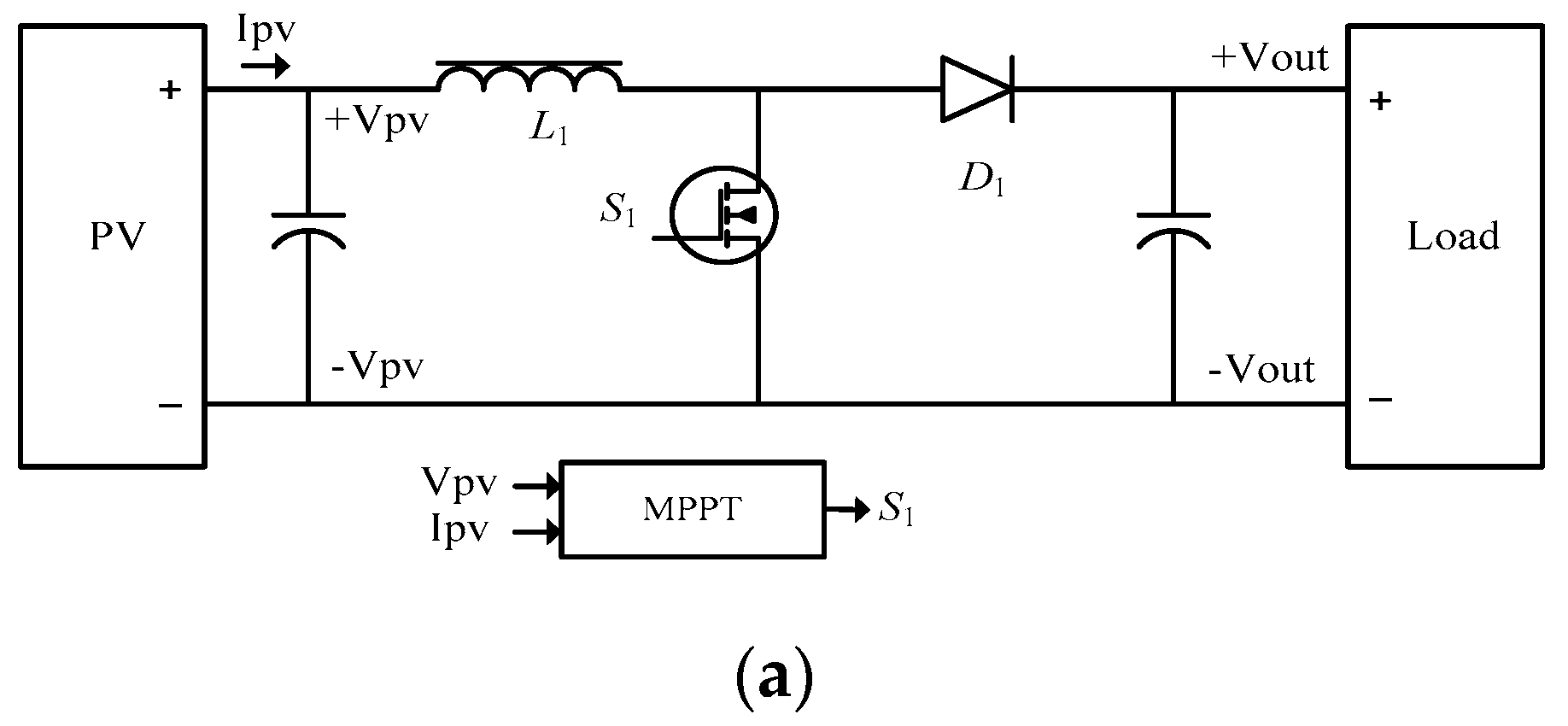
5.1. Architecture of DCO

The most popular configuration of the DCO is the series interconnection shown in Figure 13. The number of modules and the DC-DC gain ratio are designed in such a way that the sum of the (series) output voltage of all the DCO devices is compatible with the input window voltage of the central inverter. Alternatively, the DCO can also be connected in parallel, as shown in Figure 14. In this case, the gain ratio must be sufficiently high to match the input of the central inverter. However, this condition is difficult to achieve because of two contrasting requirements: the need for a high voltage gain ratio (to step up from 30 to 400 Vdc) while maintaining a high conversion efficiency [77]. Despite this drawback, several attempts have been made to utilise this configuration, such as in [78,79,80,81].
Certain DCOs are designed to work in conjunction with a specific central inverter. The idea is to allow the inverter to communicate with the DCO and thus, ensure that the former always receives the same total voltage from the string. If one of the module outputs drops because of module mismatch, the inverter adjusts other DCO devices so that their output voltage increases slightly, thus maintaining a constant voltage across the inverter. However, this requires a central inverter from the same manufacturer as the DCO. Retrofitting such a DCO into the existing installation is therefore not possible unless the inverter is also replaced. Recently, module manufacturers have started to partner with power electronics companies to create smart modules [82,83]. For this type of module, the DCO is embedded inside the junction box at the time of manufacturing. Besides enhancing the energy output, the smart module also improves safety features and provides module-level monitoring. Other benefits include simpler purchasing, inventory, and site logistics, while also reducing labor costs. Furthermore, certain products have a detachable DCO design that allows flexible serviceability.

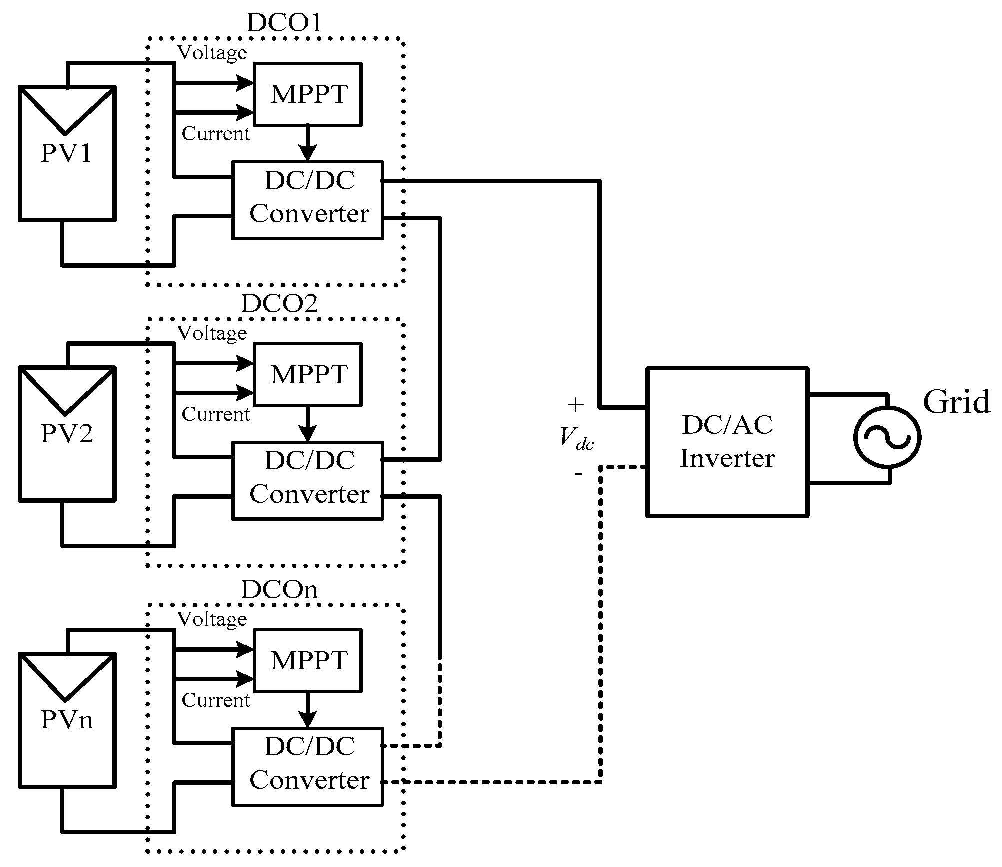
5.1.1. Series-connected DCOs

A simple DCO topology that is based on the DC-DC boost converter topology is shown in Figure 15a. As the gain of a single-stage boost converter is limited, such a device is normally used in series connection. The DCO is nothing, but an improvised DC-DC converter (that includes MPPT), so its modes of operation are similar to those of the normal boost converter. In most cases, using the conventional MPPT, such as P&O, is sufficient to detect the MPP [28]. An improved version of the DCO is shown in Figure 15b. It is based on a four-phase interleaved boost converter [28,84,85]. The inductor, the switches, and the diodes are duplicated three times to make the four parallel branches. The circuit is driven by S1 to S4 with the same waveform, but it is shifted by a quarter of the switching period. The main advantage of the circuit is the low voltage ripple that results from the interleave arrangement.

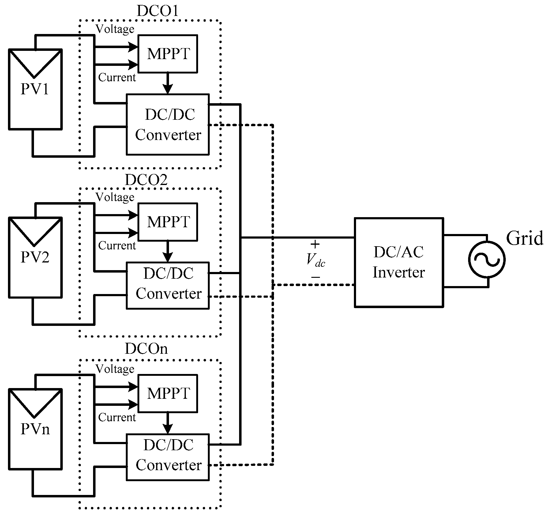
5.1.2. Parallel-connected DCOs

Despite the simplicity of the series connection, it exhibits one inherent problem: during module mismatch, it has a limitation of both maximum current and voltage rating, as explained by [86]. To be effective under such a condition, the DCO needs to be rated at a much higher voltage and power than its associated module does. These limitations can be solved with the parallel-connected DCO. However, to be compatible with the central inverter, the DC-DC converter output (inside the DCO) must be stepped up to match the window voltage of the central inverter. This is normally realized using a high frequency transformer. For example, in [70], the full-bridge circuit on the primary side is used to convert the DC into high-frequency AC, as shown in Figure 16. At the secondary side, the AC voltage is then rectified and filtered to generate the high-voltage DC output. Similar ideas have also been utilized by [79,80]. An improved converter that uses the soft switching technique is shown in Figure 17 [78]. Despite its high efficiency (98% peak), the circuit has an issue with the impulse current ripple at the input side. To overcome this problem, a large electrolytic capacitor is required to filter the large current ripple [50,54]. However, it results in a significant increase in the overall size and reduces the DCO lifetime [87,88].
Another solution to reduce the cost and complexity (because of the high frequency transformer) of the DCO is to use the non-isolated boost DC-DC converter. Fundamentally, the step-up gain of the boost converter can be high enough if the duty cycle can be close to unity. However, it is difficult when the turn-off period is too short, as the power device current ripple will be large, and the conduction losses will increase rapidly [89,90]. The boost converter with the coupled inductor is recommended for high voltage step-up. Figure 18 shows an example of such a circuit. The coupled inductors L1a, L2b, and L1c serve as multiple DC sources connected in series to achieve sufficient boosting. Additionally, an active clamp is added to suppress the high voltage surge by recovering the energy from the leakage inductor, L1a. An efficiency of 93.6% is reported for this topology.
Another boost DC-DC converter for DCO that incorporates the charge pump technique has been proposed by [91], as shown in Figure 19. The main switches are cross-connected between two inputs of coupled inductors. During operation, the main switches S1 and S2 alternately charge the magnetizing inductors, LM, in the parallel mode; then, the energy is discharged in series to achieve a high voltage gain. Additionally, the power diodes and capacitors are used for a charge pump. However, the losses from the couple inductors and diodes reduce its efficiency to approximately 93%.

6. Energy Recovery Circuits

This is a relatively new approach to harvest energy during module mismatch. The basic idea is to disable the function of the bypass diode and redistribute the power from the non-shaded modules to the shaded ones, such that the latter acquires approximately the same power level as the former. This is achieved by using power switches and temporary storage devices. Another feature of this technique is that it allows the utilization of the string array and central inverter. Thus, the energy recovery device can be readily retrofitted into the existing system.

6.1. Voltage Feedback Technique

Shimizu et. al. [33] proposed an energy recovery scheme to extract the lost energy in the shaded module by using the voltage feedback method. The concept is illustrated in Figure 20. Controlling S1, S4 of the H-bridge converts the DC output from the string into a high-frequency square-wave AC. With the use of a high-frequency transformer, the AC voltage is transferred to the secondary; it is then rectified, filtered, and distributed to individual modules. The transfer of power to the shaded module occurs naturally because of its relatively lower voltage compared with those of the non-shaded ones. The amount of power transferred depends on the level of shading; a higher shading means that the shaded module receives more power. In addition, the inverter requires an intelligent controller so that the appropriate amount of power is transferred. As the controller is used at the input (DC), the output side is left uncontrolled; thus, it loses the capability to control the voltage of each individual module. As a consequence, the module cannot be guaranteed to operate at the MPP. Furthermore, a transformer is utilised, so the efficiency degrades because of coupling and core losses.
To overcome the problem mentioned above, the authors in [92] replaced the bridge circuit with a flyback converter, as illustrated in Figure 21. Now, the controller can ensure that the power is transferred individually to the shaded modules. This is accomplished by adjusting the duty cycle of S1 and S2. However, there is a significant weakness in this method: as the number of modules increases, the complexity of the topology grows rapidly. A complicated algorithm is needed to determine the correct duty cycle for each switch in order to maximize the power extracted by the central inverter.

6.2. Current Diversion Technique

The energy recovery using the current diversion scheme is shown in Figure 22 [32,33,70]. To illustrate its operation, a system with two modules is given as an example. In this case, PV1 is shaded, whereas PV2 receives full radiance. Let us assume that the peak current is 2 A and 4 A for PV1 and PV2, respectively. During shading, the current that flows through the string is limited to the current of the shaded module, i.e., 2 A. The remaining 2 A from the non-shaded module (PV2) is diverted from the string by turning on S1 and S2 in a complementary manner. The duty cycle is set to 50%. The energy of the diverted current is stored temporarily in L1. Because of a 50% duty cycle, a 1 A current flows through S1 and the other 1 A through S2. As a result, a total of 3 A flows into the central inverter. Furthermore, a bypass diode is absent, so a voltage will appear across PV1. Thus, the output voltage is a summation of PV1 and PV2; consequently, the output power is increased. Note that the multiple-peak P-V curve (because of the activation of the bypass diode) is now transformed into a unique peak. Thus, the conventional MPPT (of the central inverter), such as P&O, can be readily utilized to detect the MPP. The 50% duty can be fine-tuned to further optimize the power that can extracted from the string. For a string with more than two modules, the basic topology in Figure 22 is combined to form the multi-stage circuit, as depicted in Figure 21 [32,33]. An improved version of the energy recovery circuit using this approach has been proposed by [34].

6.3. Power Equalizer Technique

Another type of energy recovery circuit, based on the power equalizer technique, is proposed by [93]. The equalization is achieved by sharing the energy within the string with the use of a single inductor. The concept is illustrated in Figure 23a, using the following shading condition: PV1 is shaded, whereas PV2, PV3, and PV4 are not. When PV1 is shaded, the inductor L1 charges through S7, S2, and diodes D7 and D2. Because of the activation of these switches, the energy from the non-shaded modules is stored in L1. During the discharging phase, S7, S2, and D10 conduct. The stored energy in L1 is released back to the terminal voltage of PV4, as shown in Figure 23b. This energy provides an extra current for PV4 and creates an alternative route for the string current without short-circuiting the shaded module. Thus, the energy from the non-shaded modules is shared with the shaded module until the power delivered by each module in the string is balanced. For simple shading patterns, the circuit accurately adjusts the duty cycle to extract the maximum power from the shaded modules. Although it has a high number of active devices, at any one time, only a minimal number are in operation. This results in high power conversion efficiency.

7. Comparative Evaluation

7.1. General Assessment

Table 1 summarizes the advantages and disadvantages of the micro inverter, DCO, and energy recovery circuits. It also shows several examples of the commercial product in the marketplace. However, for the energy recovery circuits, there is no available product thus far.
The PV system with the micro inverter is configured as a modular structure. Thus, system size can be expanded without effecting the existing interconnection. Moreover, the modularity and absence of a central inverter allows for simple installation (plug and play). On the contrary, the DCO is configured along with a central inverter; which means that the structure is not modular. As mentioned, the DCO is configured in series before being connected to a central inverter. If one device fails, the entire string must be shut down. One of the main drawbacks of a micro inverter is that it cannot be directly connected to a storage system. To achieve this, an additional AC-DC conversion stage is required. On the other hand, the output of DCO is DC. Consequently, it can be directly connected to a charge controller. Another disadvantage of micro inverter is power clipping. If output of the module is higher than a micro inverter, the additional power cannot be harvested.
A central inverter usually requires a minimum system voltage over 125 V. A micro inverter (for example, the Enphase M215) requires a minimum voltage of 22 V to start operation (this is known as the kicking voltage). In comparison, the DCO (for example, the SolarEdge P320) has a much lower kicking voltage, i.e. 5 V. Since the DCO can be triggered at a lower voltage, it will produce more power during the shading condition, as well as early turn-on and late turn-off. The cost of wiring for micro inverter is less than the DCO because it uses an AC switch gear and a AC cable. In addition, the DC voltage to be handled by micro inverter is much lower, because it is directly connected to each module.
Most energy recovery circuits proposed in the literature function as retrofit with the central inverter. They are not normally designed with independent MPPTs; consequently, the module is not tracked individually. This explains the lower efficiency exhibits by the energy recovery circuit compared to a micro inverter and DCO.

7.1.1. Performance Evaluation

The performance of the reviewed topologies (discussed in this paper) is evaluated based on the following criteria: (1) component count and their ratings, (2) converter efficiency, and (3) converter lifetime. The results are summarized in Table 2.

7.1.2. Component Count

Component count is defined as the number of active devices (switches and diodes) and passive components (inductors and capacitors) required to build a basic power conversion circuit. Auxiliary components, i.e., for protection, gate drivers, and controllers, are not included. In general, the single-stage flyback micro inverter requires the least components compared to the other types in the micro inverter category. For example, the simple flyback circuit in [22] requires only three switching devices, two inductors, one capacitor, and a transformer. However, the switches need to withstand high voltage and current stresses. A high-voltage and high-current MOSFET is not feasible because of the higher Rds(on) and costs associated with such a device. To reduce the current, an interleaved micro inverter has been proposed [50]. As the interleaved micro inverter consists of several phases, the current is shared; thus, a low current MOSFET can be used. However, the interleaved circuit requires additional components; for example, the two-phase interleaved micro inverter suggested by [50] is built using six switches (two of them operated at a high frequency), two transformers, three inductors, and four capacitors. Despite the improvement in the current ratings of the switches, the circuit still requires a large DC link capacitor (7300 µF). Alternatively, the flyback with a power decoupling circuit can be used to reduce the DC link capacitors, as demonstrated by [58,59].
The transformerless topology reduces the component count because of the absence of the transformer. For example, the basic topology [65] requires only four switches, two inductors, and a capacitor. Note that the transformerless micro inverter exhibits leakage current, as explained in Section 4.1.2. To solve this problem, an auxiliary circuit that reduces the leakage current has been proposed in [68]. However, the solution increases the number of switches and passive components. It must be further noted that the component count shown in Table 2 does not include the DC-DC boost circuit at the front-end of the micro inverter. If included, the number of components increases significantly, depending on the types of converters used to step up the voltage. Note that a DC-DC converter is required to match the difference between the input (module) and output (grid) sides of the voltage.
Generally, the DCO requires a lower component count than the micro inverter does. As the DCO is connected in series (to feed the central inverter), the voltage across each module is low; thus, the DC-DC converter inside the DCO can capitalize on the low-cost MOSFET for its design. For example, the topology in [28] implements a four-phase interleaved boost converter that requires only four switches, in addition to four inductors and capacitors. Furthermore, the low-voltage MOSFET allows the circuit to be integrated with the MPPT controller on a single semiconductor substrate. The least component count is offered by the energy recovery technique. The circuit in [32] requires one power switch and inductor per module, whereas in [93], only one inductor is needed for four modules. As the circuit is connected in parallel to each module, the blocking voltage for the switch is low. As in the case of DCO (connected in series), it does not need a voltage step-up mechanism, which is advantageous because of the absence of the front-end DC-DC boost converter or transformer.

7.2. Efficiency

In PV literature, efficiency is divided into two types, namely conversion and MPPT efficiency. The former is the ratio of the output to the input power of the converter, whereas the latter is a measure of the MPPT algorithm’s ability to track the MPP. Table 2 shows the conversion efficiency only; the MPPT efficiency is assumed to be the same for all topologies (wherever applicable). Furthermore, the numbers shown in the table are based on peak efficiency calculation. The weighted efficiency (for example, the European weighted efficiency, ηEURO) is not considered.
The isolated micro inverter with a high-frequency transformer exhibits the lowest efficiency among all the circuits. This can be justified because of significant core and winding losses. In particular, the circuit in [58] has a very low efficiency (70%), as a result of the auxiliary power decoupling circuit. Efficiency is improved by utilizing the transformer leakage energy [59]. The transformerless topology significantly increases the efficiency of the micro inverter. However, the efficiency number shown in Table 2 does not consider the integration with a front-end DC-DC boost converter.
The DCO exhibits higher efficiency (compared with the micro inverter and energy recovery) because of its simpler design. When it is configured in a series connection, the need for the voltage step-up mechanism is eliminated. However, as explained earlier, under a certain module mismatch condition, its MPPT efficiency is reduced because of the limitation in its power rating. This drawback can be resolved by a parallel configuration, but at the cost of an additional DC-DC boost converter. Efficiency can be increased by using soft-switching techniques or utilizing charge pump boosting, as shown by [78] and [91], respectively. The energy recovery scheme works by diverting some of its string currents during module mismatch. However, because of the complexity of the circuit, it lacks the ability to precisely control the power flow to each module. As a result, it exhibits a lower efficiency. Nevertheless, the power circuit is always turned off when the shading is lacking a feature that is not available in the micro inverter and DCO. This compensates for the drop-in efficiency because of inaccurate control of power flow.

7.3. Component Lifetime

The hardware solution requires the devices to be fitted under the module, thus exposing itself to harsh environmental conditions. Its lifetime is subjected to the ability of the individual components to withstand heat and humidity without breaking down. The authors in [54] suggested that the reliability of the micro inverter depends primarily on the DC link capacitor that is used to smoothen the large, low-frequency pulsating current between the module and the device. The flyback circuit [22,50] requires a large capacitor (in thousands of µF) for this purpose. Normally, the electrolytic type is used because of its low cost and small footprint. However, the intrinsic construction of the electrolytic results in a short operational lifetime. The improved flyback circuit [58] dramatically reduces the DC link capacitor (to less than 50 µF). As the capacitance value is small, the more reliable types, such as ceramic or film, can be used. The utilization of such a capacitor significantly extends the lifetime of the micro inverter.
The DCO requires a much lower DC link capacitor (below 50 µF) because it does not experience a large pulsating current. A similar scenario is observed for the energy recovery topology, in which a large input capacitor is not needed. The capacitors in the circuit are mainly used to filter high-frequency harmonics. Their values are small (in tens of µF), and ceramic and film can be utilized accordingly. Therefore, a much longer lifetime for the DCO and energy recovery circuit can be expected.

7.4. Practical Aspects for Consideration

As the DCO connection to the central inverter is DC, it requires DC cables and protection (switchgears). Despite the much-improved safety of the high-voltage DC system, the protection of rooftop installation remains an issue. Furthermore, if the (single) string inverter fails, the entire system shuts down. In some cases, this happens even if a single DCO device fails. In addition, as the DCO (in series) needs to match the window voltage of the inverter, it needs to be correctly designed. On the positive side, for larger installations, the price of a string inverter becomes lower with its increased size; thus, it offers a slight advantage in terms of capital cost because of scalability. For a system that utilizes batteries, the DCO is advantageous; its integration is simpler, as the DC wiring goes all the way to the central inverter.
On the other hand, the size of the micro inverter only needs to match the power output of the panel, hence its much simpler design. The number of devices is limited by the capacity of AC branches, i.e., the power limit that the AC cable and plug can accommodate. If more panels need to be added in the future, the system can be expanded as long as the AC branch limit is not breached. Unlike the DCO system, if one of the micro inverters fails, the rest keeps on working because there is no single point of failure. However, as most micro inverter products do not have an exposed output DC (terminal), integration to the battery is more expensive.
Another factor to consider is the reliability of the panels that the inverter or DCO are attached to. There is a possibility for potential-induced degradation (PID) failure caused by high voltages across the module. PID is one of the more common causes of module failure in the medium to long term (5–20 years after installation). As a micro inverter keeps the modules at a much lower DC voltage than DCO, the chances for it to happen in the former are lower.
For the energy recovery circuit, assessing its practical performance is difficult because most of the ideas are still under development. However, one of the known main advantages of an energy recovery circuit is its ability to be retrofitted in parallel into the existing system with a central inverter. Therefore, if there is a need to mitigate the module mismatch, it can be added with minimal wiring. Moreover, if the recovery circuit fails, it can be isolated from the main DC bus without shutting down the entire system.

8. Conclusions

This study reviews important topologies for the micro inverter, DCO, and energy recovery circuits. The objective was to investigate their performance in mitigating the effect of module mismatch for the PV system. The main functions, operations, merits, and drawbacks of the important circuits within each category are highlighted. In addition, a technical evaluation is made to compare their respective performances. The choice of which technology to use depends on the needs of the system owner. If the central inverter is to be maintained, the DCO is a good option. However, a micro inverter has its own advantages, as the modules can be connected to the grid in a distributed fashion, i.e., without the need to form a conventional string. This configuration can be useful, particularly when the space for installation is limited, such as rooftops. On the other hand, energy recovery circuits are quite promising, even if they are still under laboratory development. As PV systems have a long lifecycle (typically over 20 years), hardware solutions appear to be attractive because of their long-term financial benefits. However, more in-depth study is needed to determine the feasibility of this approach.

Author Contributions

Conceptualization: Z.S.; Methodology/investigation: M.Z.R.; Validation: M.R.; Formal analysis: H.B.; Writing—original draft preparation, Z.S., M.Z.R.; Writing—review and editing: H.S.; Supervision, H.B., Z.S.; Project administration: H.B., H.S.; Funding acquisition: M.R.

Funding

The research and APC was funded by DF-176-135-1441 (King Abdulaziz University, Jeddah, Saudi Arabia). The research was also funded by the Ministry of Higher Education, Malaysia, under the Malaysia Rising Star Award (MRSA) grant, which is managed by Universiti Teknologi Malaysia, Johor Bahru, Malaysia under Vot. No. R.J130000.7823.4F919.

Conflicts of Interest

The authors declare no conflict of interest.

References

  1. Solangi, K.H.; Islam, M.R.; Saidur, R.; Rahim, N.A.; Fayaz, H. A review on global solar energy policy. Renew. Sustain. Energy Rev. 2011, 15, 2149–2163. [Google Scholar] [CrossRef]
  2. REN21. Renewables 2016 Global Status Report; Renewables Now: Paris, France, 2016. [Google Scholar]
  3. Maki, A.; Valkealahti, S. Power Losses in Long String and Parallel-Connected Short Strings of Series-Connected Silicon-Based Photovoltaic Modules Due to Partial Shading Conditions. IEEE Trans. Energy Convers. 2012, 27, 173–183. [Google Scholar] [CrossRef]
  4. Myrzik, J.M.A.; Calais, M. String and module integrated inverters for single-phase grid connected photovoltaic systems—A review. IEEE Bologna Power Tech Conf. Proc. 2003, 2, 430–437. [Google Scholar]
  5. Choi, U.M.; Blaabjerg, F.; Lee, K.B. Control Strategy of Two Capacitor Voltages for Separate MPPTs in Photovoltaic Systems Using Neutral-Point-Clamped Inverters. IEEE Trans. Ind. Appl. 2015, 51, 3295–3303. [Google Scholar] [CrossRef]
  6. Tsang, K.M.; Chan, W.L. Maximum power point tracking for PV systems under partial shading conditions using current sweeping. Energy Convers. Manag. 2015, 93, 249–258. [Google Scholar] [CrossRef]
  7. Kheldoun, A.; Bradai, R.; Boukenoui, R.; Mellit, A. A new Golden Section method-based maximum power point tracking algorithm for photovoltaic systems. Energy Convers. Manag. 2016, 111, 125–136. [Google Scholar] [CrossRef]
  8. Jazayeri, M.; Jazayeri, K.; Uysal, S. Adaptive photovoltaic array reconfiguration based on real cloud patterns to mitigate effects of non-uniform spatial irradiance profiles. Sol. Energy 2017, 155, 506–516. [Google Scholar] [CrossRef]
  9. Mamun, M.A.A.; Hasanuzzaman, M.; Selvaraj, J. Experimental investigation of the effect of partial shading on photovoltaic performance. IET Renew. Power Gener. 2017, 11, 912–921. [Google Scholar] [CrossRef]
  10. Silverman, T.J.; Mansfield, L.; Repins, I.; Kurtz, S. Damage in Monolithic Thin-Film Photovoltaic Modules Due to Partial Shade. IEEE J. Photovolt. 2016, 6, 1333–1338. [Google Scholar] [CrossRef]
  11. Kim, K.A.; Seo, G.S.; Cho, B.H.; Krein, P.T. Photovoltaic Hot-Spot Detection for Solar Panel Substrings Using AC Parameter Characterization. IEEE Trans. Power Electron. 2016, 31, 1121–1130. [Google Scholar] [CrossRef]
  12. Imtiaz, A.M.; Khan, F.H.; Kamath, H. All-in-One Photovoltaic Power System: Features and Challenges Involved in Cell-Level Power Conversion in ac Solar Cells. IEEE Ind. Appl. Mag. 2013, 19, 12–23. [Google Scholar] [CrossRef]
  13. Jantharamin, N. Optimal Control and Management of Photovoltaic Power Generation Systems. Ph.D. Thesis, University of Leeds, Leeds, UK, 2008. [Google Scholar]
  14. Mohammedi, A.; Mezzai, N.; Rekioua, D.; Rekioua, T. Impact of shadow on the performances of a domestic photovoltaic pumping system incorporating an MPPT control: A case study in Bejaia, North Algeria. Energy Convers. Manag. 2014, 84, 20–29. [Google Scholar] [CrossRef]
  15. Ishaque, K.; Salam, Z. A Deterministic Particle Swarm Optimization Maximum Power Point Tracker for Photovoltaic System under Partial Shading Condition. IEEE Trans. Ind. Electron. 2013, 60, 3195–3206. [Google Scholar] [CrossRef]
  16. Ghanbari, T. Hot spot detection and prevention using a simple method in photovoltaic panels. IET Gener. Transm. Distrib. 2017, 11, 883–890. [Google Scholar] [CrossRef]
  17. Ahmed, J.; Salam, Z. An Enhanced Adaptive P&O MPPT for Fast and Efficient Tracking Under Varying Environmental Conditions. IEEE Trans. Sustain. Energy 2018, 9, 1487–1496. [Google Scholar]
  18. Ishaque, K.; Salam, Z.; Amjad, M.; Mekhilef, S. An Improved Particle Swarm Optimization (PSO) Based MPPT for PV With Reduced Steady-State Oscillation. IEEE Trans. Power Electron. 2012, 27, 3627–3638. [Google Scholar] [CrossRef]
  19. Adly, M.; Besheer, A.H. An optimized fuzzy maximum power point tracker for stand alone photovoltaic systems: Ant colony approach. In Proceedings of the 7th IEEE Conference on Industrial Electronics and Applications (ICIEA), Singapore, 18–20 July 2012; pp. 113–119. [Google Scholar]
  20. Guruambeth, R.; Ramabadran, R. Fuzzy logic controller for partial shaded photovoltaic array fed modular multilevel converter. IET Power Electron. 2016, 9, 1694–1702. [Google Scholar] [CrossRef]
  21. Haibing, H.; Harb, S.; Kutkut, N.; Batarseh, I.; Shen, Z.J. A Review of Power Decoupling Techniques for Microinverters With Three Different Decoupling Capacitor Locations in PV Systems. IEEE Trans. Power Electron. 2013, 28, 2711–2726. [Google Scholar]
  22. Ankit; Sahoo, S.K.; Sukchai, S.; Yanine, F.F. Review and comparative study of single-stage inverters for a PV system. Renew. Sustain. Energy Rev. 2018, 91, 962–986. [Google Scholar] [CrossRef]
  23. Wang, F.; Feng, X.; Zhang, L.; Du, Y.; Su, J. Impedance-based analysis of grid harmonic interactions between aggregated flyback micro-inverters and the grid. IET Power Electron. 2018, 11, 453–459. [Google Scholar] [CrossRef]
  24. Patrao, I.; Garcera, G.; Figueres, E.; Gonzalez-Medina, R. Grid-tie inverter topology with maximum power extraction from two photovoltaic arrays. IET Renew. Power Gener. 2014, 8, 638–648. [Google Scholar] [CrossRef]
  25. Niazi, K.A.K.; Yang, Y.; Sera, D. Review of mismatch mitigation techniques for PV modules. IET Renew. Power Gener. 2019, 13, 2035–2050. [Google Scholar] [CrossRef]
  26. Mamarelis, E.; Petrone, G.; Spagnuolo, G. A two-steps algorithm improving the P&O steady state MPPT efficiency. Appl. Energy 2014, 113, 414–421. [Google Scholar]
  27. Ahmed, J.; Salam, Z. An improved perturb and observe (P&O) maximum power point tracking (MPPT) algorithm for higher efficiency. Appl. Energy 2015, 150, 97–108. [Google Scholar]
  28. Ragonese, D.; Ragusa, M. Designing with the SPV1020, an Interleaved Boost Converter with MPPT Algoritham. Available online: www.st.com (accessed on 10 October 2019).
  29. Ishaque, K. Deterministic Particle Swarm Optimization Method for Maximum Power Point Tracking of Photovoltaic System. Ph.D. Thesis, Universiti Teknologi Malaysia, Skudai, Malaysia, 2012. [Google Scholar]
  30. Jordan, D.; Kurtz, S. 3—Photovoltaic Module Stability and Reliability. In The Performance of Photovoltaic (PV) Systems; Pearsall, N., Ed.; Woodhead Publishing: Cambridge, UK, 2017; pp. 71–101. [Google Scholar]
  31. Meyer, E.L.; Dyk, E.E. Assessing the reliability and degradation of photovoltaic module performance parameters. IEEE Trans. Reliab. 2004, 53, 83–92. [Google Scholar] [CrossRef]
  32. Shimizu, T.; Hashimoto, O.; Kimura, G. A novel high-performance utility-interactive photovoltaic inverter system. IEEE Trans. Power Electron. 2003, 18, 704–711. [Google Scholar] [CrossRef]
  33. Shimizu, T.; Hirakata, M.; Kamezawa, T.; Watanabe, H. Generation control circuit for photovoltaic modules. IEEE Trans. Power Electron. 2001, 16, 293–300. [Google Scholar] [CrossRef]
  34. Ramli, M.; Salam, Z. A Simple Energy Recovery Scheme for to Harvest the Energy from Shaded Photovoltaic Modules During Partial Shading. IEEE Trans. Power Electron. 2014, 29, 6458–6471. [Google Scholar] [CrossRef]
  35. Guan-Chyun, H.; Hung, I.H.; Cheng-Yuan, T.; Chi-Hao, W. Photovoltaic Power-Increment-Aided Incremental-Conductance MPPT With Two-Phased Tracking. IEEE Trans. Power Electron. 2013, 28, 2895–2911. [Google Scholar]
  36. Safari, A.; Mekhilef, S. Simulation and Hardware Implementation of Incremental Conductance MPPT with Direct Control Method Using Cuk Converter. IEEE Trans. Ind. Electron. 2011, 58, 1154–1161. [Google Scholar] [CrossRef]
  37. Mohanty, S.; Subudhi, B.; Ray, P.K. A New MPPT Design Using Grey Wolf Optimization Technique for Photovoltaic System Under Partial Shading Conditions. IEEE Trans. Sustain. Energy 2016, 7, 181–188. [Google Scholar] [CrossRef]
  38. Daraban, S.; Petreus, D.; Morel, C. A novel MPPT (maximum power point tracking) algorithm based on a modified genetic algorithm specialized on tracking the global maximum power point in photovoltaic systems affected by partial shading. Energy 2014, 74, 374–388. [Google Scholar] [CrossRef]
  39. Koad, R.B.A.; Zobaa, A.F.; El-Shahat, A. A Novel MPPT Algorithm Based on Particle Swarm Optimization for Photovoltaic Systems. IEEE Trans. Sustain. Energy 2017, 8, 468–476. [Google Scholar] [CrossRef]
  40. Roy, J.; Ayyanar, R. GaN based transformer-less microinverter with coupled inductor interleaved boost and half bridge voltage swing inverter. In Proceedings of the IEEE Applied Power Electronics Conference and Exposition (APEC), San Antonio, TX, USA, 4–8 March 2018; pp. 381–386. [Google Scholar]
  41. Kale, R.; Thale, S.; Agarwal, V. Design and implementation of a solar PV panel integrated inverter with multi-mode operation capability. In Proceedings of the IEEE 39th Photovoltaic Specialists Conference (PVSC), Tampa, FL, USA, 16–21 June 2013; pp. 2959–2964. [Google Scholar]
  42. Kjaer, S.B.; Pedersen, J.K.; Blaabjerg, F. A review of single-phase grid-connected inverters for photovoltaic modules. IEEE Trans. Ind. Appl. 2005, 41, 1292–1306. [Google Scholar] [CrossRef]
  43. Sukesh, N.; Pahlevaninezhad, M.; Jain, P.K. Analysis and Implementation of a Single-Stage Flyback PV Microinverter With Soft Switching. IEEE Trans. Ind. Electron. 2014, 61, 1819–1833. [Google Scholar] [CrossRef]
  44. Rana, A.S.; Nasir, M.; Khan, H.A. String level optimisation on grid-tied solar PV systems to reduce partial shading loss. IET Renew. Power Gener. 2018, 12, 143–148. [Google Scholar] [CrossRef]
  45. Rana, A.S.; Khan, H.A. String level optimization on grid-tied solar PV systems for minimizing soft shading power loss. IET Renew. Power Gener. 2017, 12, 143–148. [Google Scholar] [CrossRef]
  46. Keshani, M.; Adib, E.; Farzanehfard, H. Micro-inverter based on single-ended primary-inductance converter topology with an active clamp power decoupling. IET Power Electron. 2018, 11, 73–81. [Google Scholar] [CrossRef]
  47. Zhao, B.; Abramovitz, A. Single stage high gain charge pump assisted micro-inverter. Sol. Energy 2016, 139, 81–84. [Google Scholar] [CrossRef]
  48. Elanchezhian, P.; Chinnaiyan, V.K. Modeling and Simulation of High-Efficiency Interleaved Flyback Micro-inverter For Photovoltaic Applications. Mater. Today Proc. 2017, 4, 10417–10421. [Google Scholar] [CrossRef]
  49. Famoso, F.; Lanzafame, R.; Maenza, S.; Scandura, P.F. Performance Comparison between Micro-inverter and String-inverter Photovoltaic Systems. Energy Procedia 2015, 81, 526–539. [Google Scholar] [CrossRef] [Green Version]
  50. Edwin, F.F.; Xiao, W.; Khadkikar, V. Dynamic modeling and control of interleaved flyback module-integrated converter for PV power applications. IEEE Trans. Ind. Electron. 2014, 61, 1377–1388. [Google Scholar] [CrossRef]
  51. Xiao, W.; Ozog, N.; Dunford, W.G. Topology study of photovoltaic interface for maximum power point tracking. IEEE Trans. Ind. Electron. 2007, 54, 1696–1704. [Google Scholar] [CrossRef]
  52. Osborne, M. LG Launches Its First AC Module with Integrated Microinverter to Simplify Installations. Available online: https://www.pv-tech.org (accessed on 27 July 2017).
  53. McCabe, J. PV Micro Inverters and Optimizers: Not Just for Lazy Designers. Available online: https://www.renewableenergyworld.com/2011/06/01/pv-micro-inverters-and-optimizers-not-just-for-lazy-designers/#gref (accessed on 10 October 2019).
  54. Hasan, R.; Mekhilef, S.; Seyedmahmoudian, M.; Horan, B. Grid-connected isolated PV microinverters: A review. Renew. Sustain. Energy Rev. 2017, 67, 1065–1080. [Google Scholar] [CrossRef]
  55. Kouro, S.; Leon, J.I.; Vinnikov, D.; Franquelo, L.G. Grid-connected photovoltaic systems: An overview of recent research and emerging PV converter technology. IEEE Ind. Electron. Mag. 2015, 9, 47–61. [Google Scholar] [CrossRef]
  56. Çelik, Ö.; Teke, A.; Tan, A. Overview of micro-inverters as a challenging technology in photovoltaic applications. Renew. Sustain. Energy Rev. 2018, 82, 3191–3206. [Google Scholar] [CrossRef]
  57. Woei-Luen, C.; Chung-Ting, T. Optimal Balancing Control for Tracking Theoretical Global MPP of Series PV Modules Subject to Partial Shading. IEEE Trans. Ind. Electron. 2015, 62, 4837–4848. [Google Scholar]
  58. Shimizu, T.; Wada, K.; Nakamura, N. Flyback-type single-phase utility interactive inverter with power pulsation decoupling on the DC input for an AC photovoltaic module system. IEEE Trans. Power Electron. 2006, 21, 1264–1272. [Google Scholar] [CrossRef]
  59. Hu, H.; Harb, S.; Fang, X.; Zhang, D.; Zhang, Q.; Shen, Z.J.; Batarseh, I. A three-port flyback for PV microinverter applications with power pulsation decoupling capability. IEEE Trans. Power Electron. 2012, 27, 3953–3964. [Google Scholar] [CrossRef]
  60. Cha, W.-J.; Kwon, J.-M.; Kwon, B.-H. Highly efficient step-up dc–dc converter for photovoltaic micro-inverter. Sol. Energy 2016, 135, 14–21. [Google Scholar] [CrossRef]
  61. Kim, Y.-H.; Ji, Y.-H.; Kim, J.-G.; Jung, Y.-C.; Won, C.-Y. A new control strategy for improving weighted efficiency in photovoltaic AC module-type interleaved flyback inverters. IEEE Trans. Power Electron. 2013, 28, 2688–2699. [Google Scholar] [CrossRef]
  62. Khan, A.; Ben-Brahim, L.; Gastli, A.; Benammar, M. Review and simulation of leakage current in transformerless microinverters for PV applications. Renew. Sustain. Energy Rev. 2017, 74, 1240–1256. [Google Scholar] [CrossRef]
  63. Ahmad, Z.; Singh, S.N. Improved modulation strategy for single phase grid connected transformerless PV inverter topologies with reactive power generation capability. Sol. Energy 2018, 163, 356–375. [Google Scholar] [CrossRef]
  64. Trujillo, C.L.; Santamaría, F.; Gaona, E.E. Modeling and testing of two-stage grid-connected photovoltaic micro-inverters. Renew. Energy 2016, 99, 533–542. [Google Scholar] [CrossRef]
  65. Schmidt, H.; Christoph, S.; Ketterer, J. Current Inverter for Direct/Alternating Currents, has Direct and Alternating Connections with an Intermediate Power Store, a Bridge Circuit, Rectifier Diodes and a Inductive Choke. Ger. Pat. DE10 2003, 221, A1. [Google Scholar]
  66. Chen, B.; Gu, B.; Zhang, L.; Zahid, Z.U.; Lai, J.-S.J.; Liao, Z.; Hao, R. A high-efficiency MOSFET transformerless inverter for nonisolated microinverter applications. IEEE Trans. Power Electron. 2015, 30, 3610–3622. [Google Scholar] [CrossRef]
  67. Kranzer, D.; Wilhelm, C.; Reiners, F.; Burger, B. In Application of normally-off SiC-JFETs in photovoltaic inverters. In Proceedings of the 13th European Conference on Power Electronics and Applications, Barcelona, Spain, 8–10 September 2009; pp. 1–6. [Google Scholar]
  68. Kerekes, T.; Teodorescu, R.; Rodríguez, P.; Vázquez, G.; Aldabas, E. A new high-efficiency single-phase transformerless PV inverter topology. IEEE Trans. Ind. Electron. 2011, 58, 184–191. [Google Scholar] [CrossRef] [Green Version]
  69. Yang, B.; Li, W.; Gu, Y.; Cui, W.; He, X. Improved transformerless inverter with common-mode leakage current elimination for a photovoltaic grid-connected power system. IEEE Trans. Power Electron. 2012, 27, 752–762. [Google Scholar] [CrossRef]
  70. Walker, G.R.; Sernia, P.C. Cascaded DC-DC converter connection of photovoltaic modules. IEEE Trans. Power Electron. 2004, 19, 1130–1139. [Google Scholar] [CrossRef]
  71. Singh, S.N. Selection of non-isolated DC-DC converters for solar photovoltaic system. Renew. Sustain. Energy Rev. 2017, 76, 1230–1247. [Google Scholar]
  72. Walker, G.R.; Pierce, J.C. PhotoVoltaic DC-DC Module Integrated Converter for Novel Cascaded and Bypass Grid Connection Topologies; Design and Optimisation. In Proceedings of the 37th IEEE Power Electronics Specialists Conference, Jeju, Korea, 18–22 June 2006; pp. 1–7. [Google Scholar]
  73. Hossain, M.Z.; Rahim, N.A.; Selvaraj, J.A.L. Recent progress and development on power DC-DC converter topology, control, design and applications: A review. Renew. Sustain. Energy Rev. 2018, 81, 205–230. [Google Scholar] [CrossRef]
  74. Tarzamni, H.; Babaei, E.; Gharehkoushan, A.Z.; Sabahi, M. Interleaved full ZVZCS DC-DC boost converter: Analysis, design, reliability evaluations and experimental results. IET Power Electron. 2017, 10, 835–845. [Google Scholar] [CrossRef]
  75. Andrade, A.M.S.S.; Schuch, L.; Martins, M.L.d.S. High Step-Up PV Module Integrated Converter for PV Energy Harvest in FREEDM Systems. IEEE Trans. Ind. Appl. 2017, 53, 1138–1148. [Google Scholar] [CrossRef]
  76. Saadat, P.; Abbaszadeh, K. A Single-Switch High Step-Up DC-DC Converter Based on Quadratic Boost. IEEE Trans. Ind. Electron. 2016, 63, 7733–7742. [Google Scholar] [CrossRef]
  77. Sabzali, A.J.; Ismail, E.H.; Behbehani, H.M. High voltage step-up integrated double Boost–Sepic DC–DC converter for fuel-cell and photovoltaic applications. Renew. Energy 2015, 82, 44–53. [Google Scholar] [CrossRef]
  78. Zhao, X.; Zhang, L.; Born, R.; Lai, J.S. A High-Efficiency Hybrid Resonant Converter With Wide-Input Regulation for Photovoltaic Applications. IEEE Trans. Ind. Electron. 2017, 64, 3684–3695. [Google Scholar] [CrossRef]
  79. Yu, W.; York, B.; Lai, J.S. Inductorless forward-flyback soft-switching converter with dual constant on-time modulation for photovoltaic applications. In Proceedings of the IEEE Energy Conversion Congress and Exposition (ECCE), Raleigh, NC, USA, 15–20 September 2012; pp. 3549–3555. [Google Scholar]
  80. Belhimer, S.; Haddadi, M.; Mellit, A. A novel hybrid boost converter with extended duty cycles range for tracking the maximum power point in photovoltaic system applications. Int. J. Hydrog. Energy 2018, 43, 6887–6898. [Google Scholar] [CrossRef]
  81. Mitra, L.; Rout, U.K. Performance analysis of a new high gain dc–dc converter interfaced with solar photovoltaic module. Renew. Energy Focus 2017, 19, 63–74. [Google Scholar] [CrossRef]
  82. Solaredge. SolarEdge Power Optimizer-Module Embedded Solution OPJ300-LV. Available online: www.solaredge.com (accessed on 10 October 2019).
  83. Tigo Energy Module Maximizer-EC(MM-ES) Data Sheet. Available online: www.tigoenergy.com (accessed on 10 October 2019).
  84. Po-Wa, L.; Lee, Y.S.; Cheng, D.K.W.; Xiu-Cheng, L. Steady-state analysis of an interleaved boost converter with coupled inductors. IEEE Trans. Ind. Electron. 2000, 47, 787–795. [Google Scholar] [CrossRef]
  85. Yong-Seong, R.; Young-Jin, M.; Jeongpyo, P.; Changsik, Y. A Two-Phase Interleaved Power Factor Correction Boost Converter with a Variation-Tolerant Phase Shifting Technique. IEEE Trans. Power Electron 2014, 29, 1032–1040. [Google Scholar] [CrossRef]
  86. Gow, J.A.; Manning, C.D. Development of a photovoltaic array model for use in power-electronics simulation studies. IEE Proc Electr. Power Appl. 1999, 146, 193–200. [Google Scholar] [CrossRef]
  87. Sakly, J.; Abdelghani, A.B.B.; Slama-Belkhodja, I.; Sammoud, H. Reconfigurable DC/DC Converter for Efficiency and Reliability Optimization. Trans. Emerg. Sel. Top. Power Electron. 2017, 5, 1216–1224. [Google Scholar] [CrossRef]
  88. Graditi, G.; Colonnese, D.; Femia, N. Efficiency and reliability comparison of DC-DC converters for single phase grid connected photovoltaic inverters. In Proceedings of the SPEEDAM 2010, Pisa, Italy, 14–16 June 2010; pp. 140–147. [Google Scholar]
  89. Ling, R.; Zhao, G.; Huang, Q. High step-up interleaved boost converter with low switch voltage stress. Electr. Power. Syst. Res. 2015, 128, 11–18. [Google Scholar] [CrossRef]
  90. Li, W.; He, X. ZVT interleaved boost converters for high-efficiency, high step-up DC-DC conversion. IET Electr. Power Appl. 2007, 1, 284–290. [Google Scholar] [CrossRef]
  91. Cao, Y.; Samavatian, V.; Kaskani, K.; Eshraghi, H. A Novel Nonisolated Ultra-High-Voltage-Gain DC-DC Converter with Low Voltage Stress. IEEE Trans. Ind. Electron. 2017, 64, 2809–2819. [Google Scholar] [CrossRef]
  92. Qi, Z.; Xiangdong, S.; Yanru, Z.; Mikihiko, M. A novel topology for solving the partial shading problem in photovoltaic power generation system. In Proceedings of the IEEE 6th International Power Electronics and Motion Control Conference, Wuhan, China, 17–20 May 2009; pp. 2130–2135. [Google Scholar]
  93. Villa, L.F.L.; Tien-Phu, H.; Crebier, J.C.; Raison, B. A Power Electronics Equalizer Application for Partially Shaded Photovoltaic Modules. IEEE Trans. Ind. Electron. 2013, 60, 1179–1190. [Google Scholar] [CrossRef]
  94. Technology, S.S. SUNNY BOY 240. Available online: www.SMA-Australia.com.au (accessed on 10 October 2019).
  95. Enphase. Enphase Microinverters The Enphase M215. Available online: https://enphase.com/e (accessed on 10 October 2019).
  96. Power-One, A. ABB Power-One MICRO-0.3HV-I-OUTD-US > 208/240 PV Aurora Micro Inverter—300 W AC, 75Voc, IMPPT. Available online: www.abb.com/solarinverters (accessed on 10 October 2019).
  97. Enecsys. Enecsys Micro Inverters SMI-S200W-72. Available online: www.enecsys.com (accessed on 10 October 2019).
  98. Installation and Operations Manual Siemens Microinverter Model SMIINV215R60XX. Available online: www.downloads.siemens.com (accessed on 10 October 2019).
  99. SolarEdge. Power Optimizer for North America P320/P340/P370/P400/P405/P505. Available online: www.solaredge.com (accessed on 10 October 2019).
  100. Huawei. Smart PV Optimizer: SUN2000-375W-USP0. Available online: https://solar.huawei.com (accessed on 10 October 2019).
  101. Alencon. The SPOT: Alencon’s Utility Scale DC-DC Optimizer. Available online: https://alectris.com (accessed on 10 October 2019).
Figure 1. The block diagram of the P&O algorithm in the GCPV environment.
Energies 12 04321 g001
Figure 2. An example to illustrate the formation of a multi-modal P-V curve due to partial shading (a) The series-parallel array for uniform irradiation, G = 1000 W/m2, for the shaded module, G = 500 W/m2, (b) the P-V curves for each string, (c) the resultant P-V curve for the entire array.
Energies 12 04321 g002
Figure 3. Failure of P&O to track the global peak during module mismatch. Blue trace: system is in uniform irradiance. Red trace: during the module mismatch condition.
Energies 12 04321 g003
Figure 4. Techniques used in the hardware mitigation of partial shading.
Energies 12 04321 g004
Figure 5. Typical configuration of a micro inverter with the AC grid.
Energies 12 04321 g005
Figure 6. The basic flyback micro inverter circuit (without MPPT).
Energies 12 04321 g006
Figure 7. Interleaved flyback micro inverter.
Energies 12 04321 g007
Figure 8. Flyback micro inverter with auxiliary external dissipative power decoupling.
Energies 12 04321 g008
Figure 9. An improved flyback inverter utilizing leakage inductance.
Energies 12 04321 g009
Figure 10. The HERIC transformerless micro inverter (without a front-end DC-DC converter).
Energies 12 04321 g010
Figure 11. HERIC transformerless micro inverter with a bi-directional IGBT.
Energies 12 04321 g011
Figure 12. Transformerless micro inverter with two auxiliary switches.
Energies 12 04321 g012
Figure 13. DCO with the output port connected in series.
Energies 12 04321 g013
Figure 14. DCO with the output port connected in parallel.
Energies 12 04321 g014
Figure 15. (a) Basic boost DCO and (b) interleaved boost DCO.
Energies 12 04321 g015aEnergies 12 04321 g015b
Figure 16. Full-bridge DC-DC converter with a high-frequency transformer for DCO.
Energies 12 04321 g016
Figure 17. High-efficiency resonant converter for a DCO utilizing soft switching.
Energies 12 04321 g017
Figure 18. Two-phase high step-up interleaved boost converter with a couple inductor and an active clamp.
Energies 12 04321 g018
Figure 19. High step-up converter based on charge pump and boost converter.
Energies 12 04321 g019
Figure 20. Voltage feedback topology using a DC-AC inverter.
Energies 12 04321 g020
Figure 21. A voltage feedback topology using the flyback converter.
Energies 12 04321 g021
Figure 22. Basic topology of energy recovery using the current diversion technique.
Energies 12 04321 g022
Figure 23. Power equalizer circuit (a) The charging phase and the (b) discharging phase. The blue trace shows the inductor current path.
Energies 12 04321 g023
Table 1. General comparison for different hardware approaches.
Product in MarketAdvantagesDisadvantages
Micro-inverter
SMA Sunny Boy 240 [94]
Enphase M215 [95]
Power One Aurora 240 [96]
Enecsys SMI-S240W-72 [97]
Siemens SMIINV21560XX [98]
1. Modular: Expansion of system is flexible.
2. Simple connection to (plug and play) due to absence of a central inverter.
3. Low cost of low voltage AC switch gear.
1. Connection to battery is not readily available.
2. Possible power clipping.
3. Startup (kicking) voltage is higher than DCO.
DCO
Solar Edge P320 [99]
Tigo Energy MM-ES50 [83]
Huawei SUN200P-375W [100]
Alencon SPOT 600 [101]
1. DC storage can directly be connected via a charge controller.
2. Higher efficiency due to single stage.
3. Very low startup voltage.
1. Risk of potential induce degradation (PID).
2. The entire string must shut down if one DCO device fails.
Energy Recovery
No commercial product available
1. Retrofit: option to remove it, if not required.
2. Can be turned off in the absence of partial shading.
1. Low efficiency due to the absence of MPPT tracking for individual modules.
Table 2. Topology comparison of the micro-inverter, DCO, and energy recovery circuits.
Micro InverterDCOEnergy Recovery Circuits
IsolatedNon-Isolated
Reference[23][61][58][59][65][68][69][28][78][90][91][92][33][93]
Figure in text678910111215171819212223
Power rating (W)300200100100n/a50010003003001000120085400165
DC link cap. (µF)150073004046n/a2509401095n/an/an/a220220
Power switches36446564642112
Power diodes8384961064869412
Inductors13112224161110.25
Capacitors23331312246111
Transformers12110000102100
Peak eff. (%)89.095.070.090.097.894.896.698.097.093.693.0n/a90.0n/a
LifetimeShortShortLongLongn/aMedShortLongLongn/an/an/aLongLong
Note: n/a: information not available from published literatures. Med: Medium.

