Article

Study on Thermal Energy Conversion Theory in Drilling Process of Coal and Rock Mass with Different Stresses

State Key Laboratory of Mining Disaster Prevention and Control Co-Founded by Shandong Province and the Ministry of Science and Technology, Shandong University of Science and Technology, Qingdao 266590, China
*
Author to whom correspondence should be addressed.
Energies 2019, 12(22), 4282; https://doi.org/10.3390/en12224282
Submission received: 18 September 2019 / Revised: 6 November 2019 / Accepted: 7 November 2019 / Published: 10 November 2019
(This article belongs to the Special Issue Advanced Technologies for Energy Exploitation of Coals)

Abstract

:
In view of the problem that the evolutionary mechanism of bit temperature during the drilling process is still unclear and the influencing factors are complex, this paper analyzes the causes of heat generation and the factors of heat production when the drill bit interacts with the coal and rock mass. Considering the stress field distribution of coal and rock mass and the dynamic characteristics of drilling, a three-dimensional mechanical structure model of bit drilling is established in this paper, based on the energy conservation theory and introducing the friction heat micro-distribution mechanism. The corresponding relationship between coal stress and the bit temperature variation rate is obtained in this paper. Therefore, the temperature rise condition model and the coal stress identification model can be verified, combined with the existing experimental data. The result shows that the temperature of bit drilling is affected by factors such as bit geometry and drilling parameters, as well as the strength and stress state of the coal and rock. Without considering other factors, the rate of increase in bit temperature is proportional to the stress of the coal and rock mass. Based on the research results, the temperature rate of the drill bit can be used as an index to identify the stress areas of coal and rock mass. Research results provide a theoretical basis for the identification of high-stress risk areas in coal mines.

Graphical Abstract

1. Introduction

Rock burst is a dynamic phenomenon caused by mining activities, which releases huge energy due to sudden instability damage of coal and rock mass around the roadway or mining face. It is one of the major disasters in coal mining at present. With the gradual deepening of the mining depth of China’s coal mines, rock burst accidents occur frequently. The measurement and prediction technology of rock bursts must be studied urgently. A drilling yield test is a method used to find high-stress zones and predict rock burst by drilling a hole in the coal seam to observe the number of cuttings ejected and any dynamic effects such as audible knocking, grating, and jamming of the drill in the hole. In the field application, the method has a large amount of engineering and complicated operation, which limits its wide application. Due to a large amount of strain energy stored in coal or rock mass under high in-situ stress, the drilling speed of the borehole is slowed down and accompanied by the phenomena of jacking, clamping, sticking, and the increase of bit temperature [1]. If the temperature response characteristics of the drill bit during drilling can be used as a sensitive index to predict the high-stress zones of the coal seam, it will be of great significance for the prevention and control of rock bursts.
In the past decades, numerous researchers carried out many laboratory and field tests, complemented by analytical and numerical analyses, to investigate the temperature response mechanism of the drill bit. Liu et al. [2,3,4,5], Eunhye et al. [6] and Sajjad et al. [7] have studied the dynamic and energy response characteristics of drill bits and drill pipes when a roadway anchorage hole was drilled into the roof rock interface and soft interlayer by means of numerical simulations. In addition, the dynamic and energy response characteristics of the drill bit are taken as the identification indexes of roof strata for further inversion analysis. Feng et al. [8,9] used laboratory tests and numerical simulation methods to conduct drilling simulations on the sedimentary rock mass of the coal roadway roof. The results show that the drilling dynamic indexes of the anchorage hole decrease with the increase of the platen’s coefficient of roof rock on the whole, which is approximately a negative exponential. Yang et al. [10,11], Jurij et al. [12] and Alexander et al. [13] made systematic dynamic, thermodynamic, and heat transfer analyses of the drill bit drilling and excavation process, established differential equations describing the dynamics and thermodynamics of a drill bit in rock drilling, and quantitatively studied the effect of flash temperature and drilling parameters on tool failure. Pan et al. [14,15], Xu et al. [16] and others [17,18,19] have developed a chip temperature measurement device, and the variation rule of cutting temperatures under different coal body strength values and different coal body stress states in the drilling process was summarized by a laboratory test. They put forward a new method of evaluating the strength of coal by using the temperature of the coal chip. In addition, the relationship between the temperature index of the drill bit and the normal stress of the coal body was obtained, which provided a certain experimental basis for the prediction of coal body dynamic disasters. Most of the current studies [20,21,22,23,24,25,26] on borehole response characteristics mainly focus on determining the location of the roof rock interface and weak interlayer. In contrast, the method of cutting temperature prediction and prediction of the rock burst hazard area is mainly used in laboratory experiments. A theoretical system for drill bit temperature change considering factors such as bit size, coal and rock mass stress, and drilling parameters has not yet been developed. Therefore, it is necessary to establish the corresponding relationship between the bit temperature response and the coal and rock mass stress, reveal the mechanism of bit temperature rise during the process of drilling coal and rock mass, and provide theoretical guidance for predicting the high-stress rock burst danger areas by the cutting temperature method.
In this paper, the three-dimensional mechanical structure model of bit drilling is established. Based on the principles of energy conservation and thermal power conversion, the real-time correspondence between coal stress and bit temperature rate is obtained, and the bit temperature rise model and coal stress recognition model are constructed. Combined with experimental data, the correctness and reliability of the model are verified, and the theoretical basis for identifying the stress regions of different coal and rock mass by using the temperature index is provided.

2. Factors and Causes of Heat Generation in Drilling

Studies [19] have shown that the process of rock cutting and hole formation can be regarded as the rotary leap fracture process of the drill bit under the action of axial pressure and rotary cutting force, and the rock mass in the borehole must go through the processes of surface microfracture, elastic deformation, plastic deformation, crack occurrence and propagation, and brittle fracture eventually. The brittle fracture stage is the main stage in which a large number of new surfaces are generated and the rocks flake into chips. Thermal work conversion also occurs mainly in this stage. Thermal energy is distributed between the drill bit and the rocks and is reflected in the form of the temperature increase of both. When the drill bit breaks the rock and invades the coal and rock mass, the axial displacement of the drill bit per unit time is very small, so the work done by the axial force can be almost ignored. Drilling and the friction and wear of bit and rock are the main factors that cause the bit to heat up. Therefore, the temperature rise of the drill bit is mainly composed of two parts, i.e., one is the shear heat energy generated by the shear failure of the rock under the action of the cutting edge of the drill bit, and the other is the heat energy generated by the friction between the drill bit and the rock and the debris not discharged in time.
A comprehensive analysis has shown that the increase of bit temperature is not only affected by drilling speed and torque (rotational speed), the diameter of the bit, the physical characteristics of the rock itself and the stress state of the rock, but also by the number of cutting edges (usually two wings), cutting angle, front edge surface, rear edge surface, side edge surface and other factors [18]. In addition, the operation level of rig operators is also an important factor affecting the bit temperature change. The relationship between bit temperature change and its influencing factors can be expressed in Formula (1) as follows:
F = f ( v , n , p , M , N , k )
where v is the drilling speed of the bit, n is the rotation speed of the drill, p is the stress state of the coal and rock mass, M represents the mechanical properties of coal and rock mass, N corresponds to the material parameters of the drill bit (thermal conductivity, specific heat, etc.), and k accounts for the other influencing factors.
If the human factors are excluded, the material parameters, drilling parameters, and the stress state and physical properties of coal and rock mass are the main factors that affect the bit temperature during drilling. The relationship between bit temperature change and the influencing factors is shown in Figure 1. The figure shows that the greater the stress, the higher the strength, the faster the drilling speed and rotation speed, the worse the thermal conductivity and heat transfer performance of the drill bit, the greater the temperature rate of the drill bit, and, conversely, the lower the bit temperature rise rate.

3. Theory of Temperature Field Evolution of the Drill Bit

Based on the theory of shear breakage and tribology, the mechanical model of the temperature rise of the drill bit during drilling is established on the basis of the law of conservation of energy and the principle of heat work conversion.

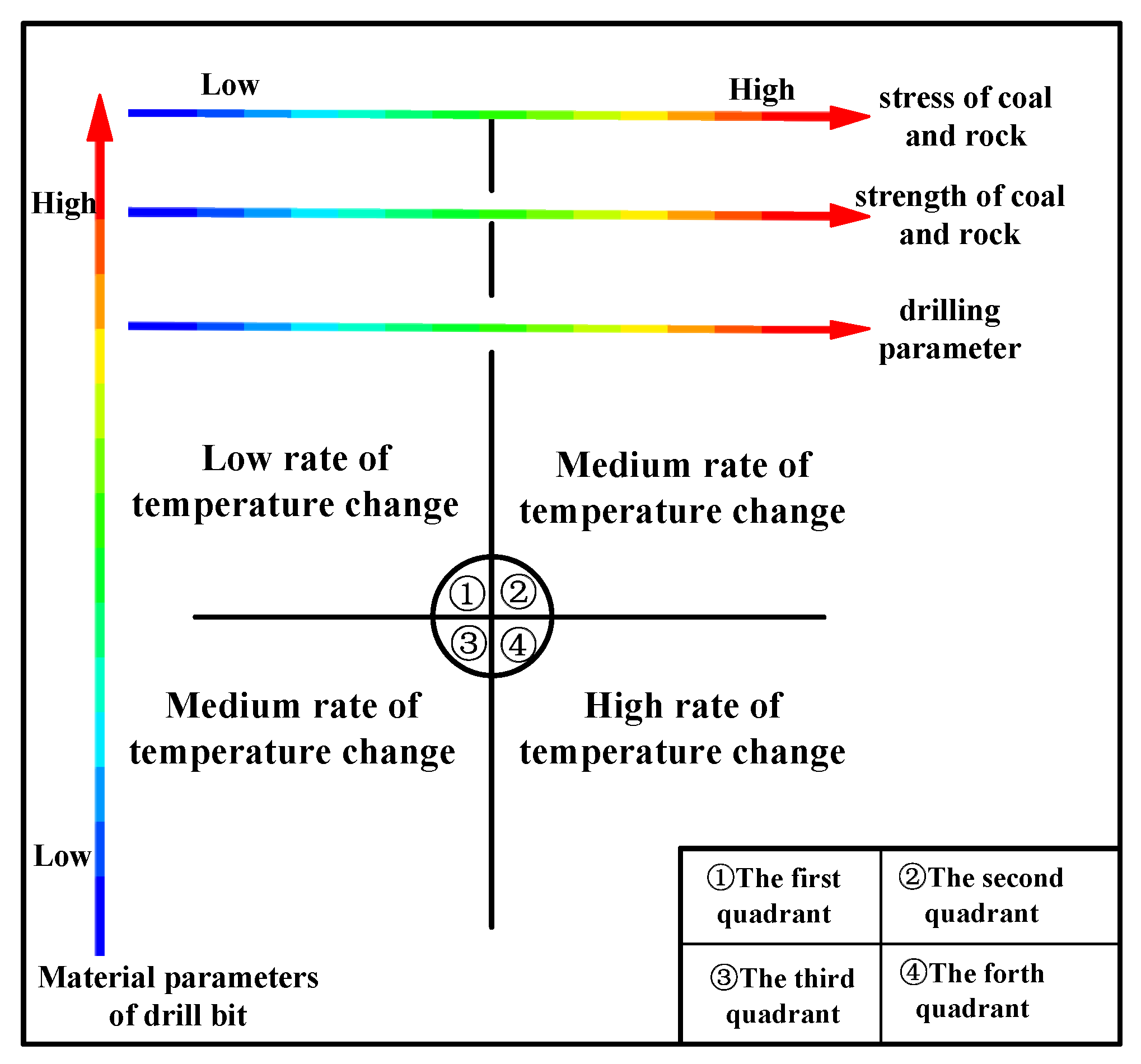
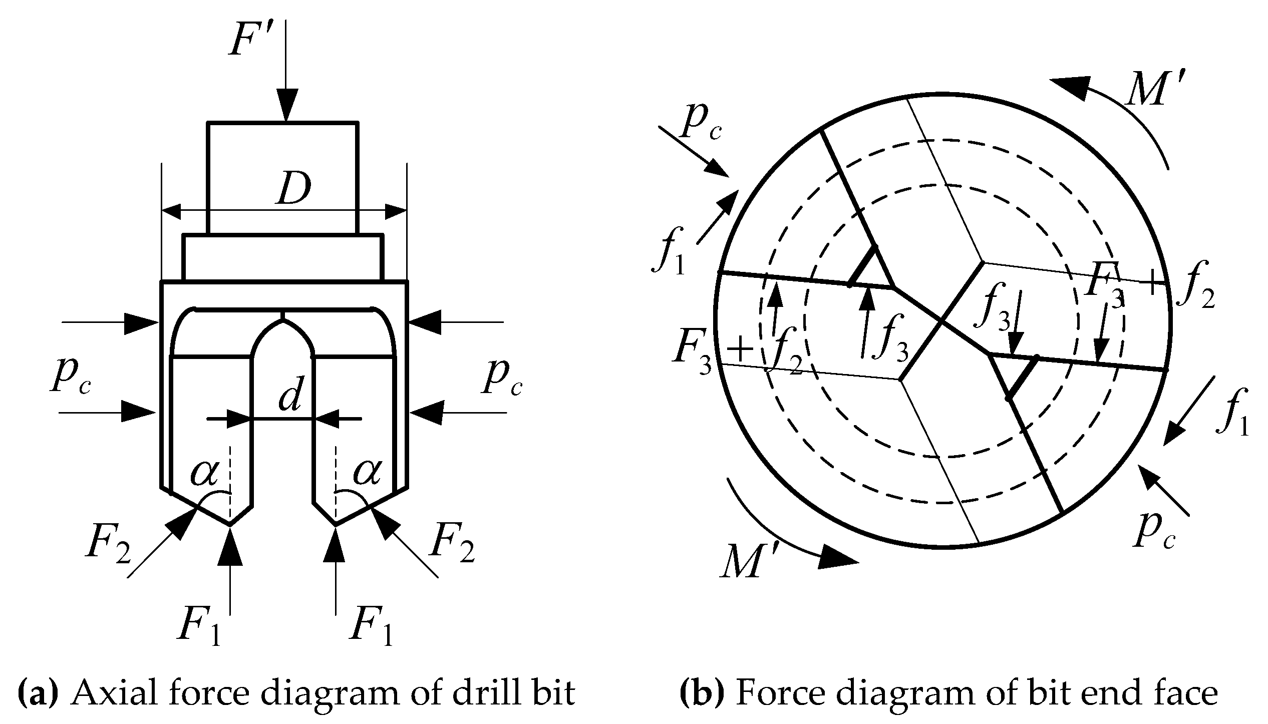
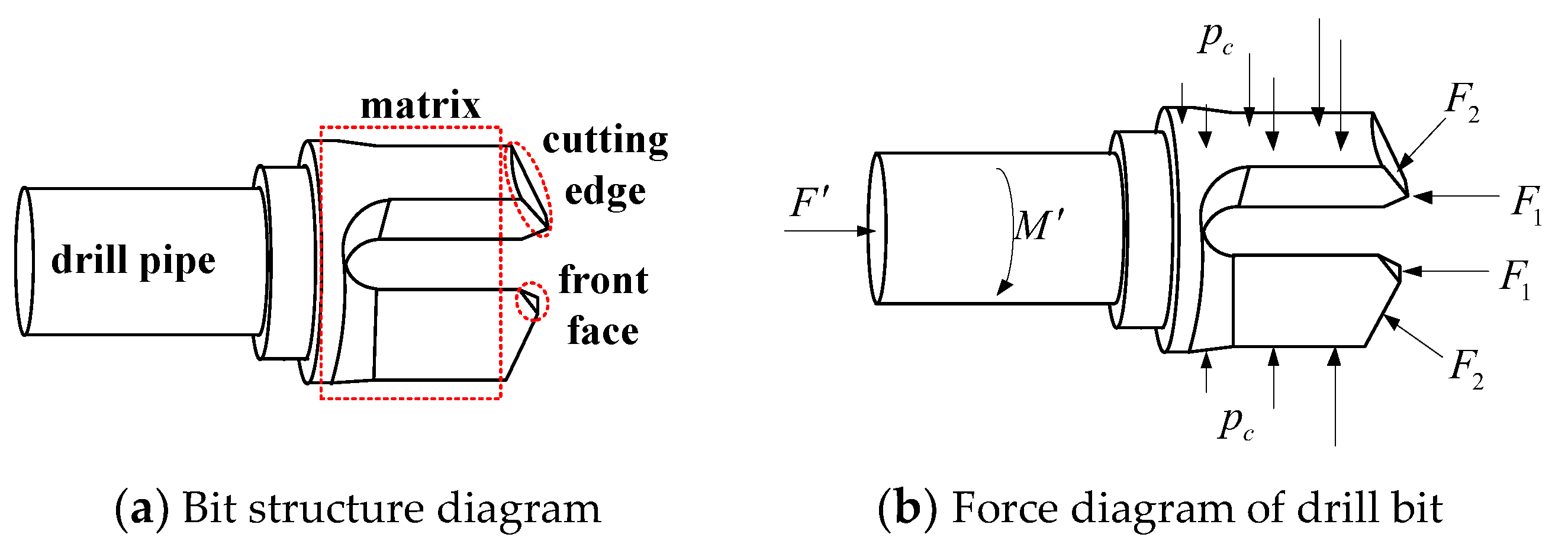
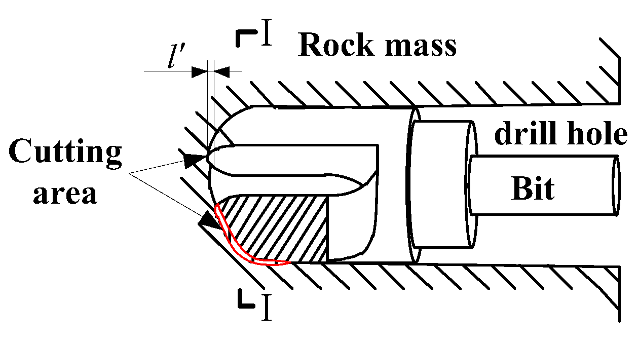
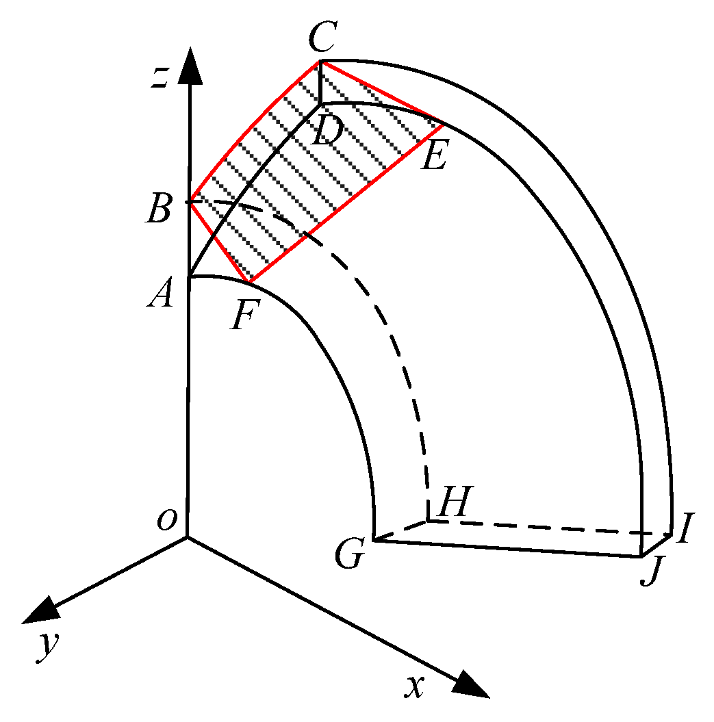
3.1. Mechanical Analysis of the Drilling Process

Figure 2a shows the structure diagram of the drill bit. According to the interaction between the drill bit and the coal in the process of drilling detection, a three-dimensional structural mechanical model of the drill bit in drilling, which is shown in Figure 2b, is established. The stress state of the drill bit is simplified, and the following assumptions were made for the model:
(1).
The coal and rock mass is a homogeneous and isotropic continuous medium;
(2).
The drilling process follows the limit stress equilibrium condition;
(3).
The drill bit is a homogeneous isotropic continuous medium.
Assuming that the coal body is under hydrostatic pressure in the drilling process, the curved cutting edge at the end of the drill bit is simplified into an inclined cutting edge at α to the axial direction, as shown in Figure 3a. According to the mechanical state of the drill bit during its movement, the equation of equilibrium is listed as follows:
{ F = 2 ( F 1 + sin α F 2 ) M = 2 ( M 1 + M 2 + M 3 + M 4 )
where F is the axial load of the drill pipe, N; F 1 is the counteracting force exerted by the coal body on the front part of the drill bit, N; F 2 is the force exerted by the coal body on the cutting edge of the drill bit, N; M is the torque input of the drill pipe, N·m; M 1 is the friction torque on the surface of the drill head (assuming that the pressure on the drill bit surface decreases uniformly from the stress value of coal body to 0), N·m; M 2 is the cutting torque on the cutting edge of the bit, N·m; M 3 is the friction torque on the cutting edge of the bit N·m; M 4 is the friction torque on the front face of the drill bit, N·m; and α is the angle between the cutting edge and the axis of the drill.
By expanding the components in Formula (2), we can obtain the following:
F 2 = p c ( D d ) b 2 sin α
M 1 = μ c m p c D 4
M 2 = F 3 sin α ( D + d ) 4
F 3 = τ S 1
M 3 = μ p c b ( D 2 d 2 ) 8
M 4 = d 2 μ F 1
where p c is the stress in the coal, N; b is the width of the inclined cutting edge, m; D is the equivalent diameter of the drill bit, m; d  is the inner diameter of the drill bit, m; μ1 is the friction coefficient between the drill bit and the coal and rock (cuttings); c is the length of the drilling head body, m; m is the width of the drill head body, m; F 3 is the reaction force of the cut rock layer on the cutting edge of the bit, N; τ is the shear strength of rock material, Pa; S 1 is the shear area when a single cutting acts on the rock, m2.
By substituting Equations (3)–(8) into Equation (2), and we can obtain the following:
{ F = 2 F 1 + p c ( D d ) b M = μ c m p c D 2 + F 3 sin α ( D + d ) 2 + μ p c b ( D 2 d 2 ) 4 + d μ F 1

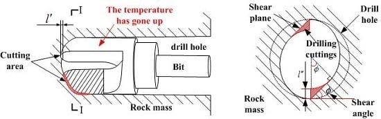
3.2. Generation and Distribution of Heat

It is assumed that the drill bit, rock, and cuttings are closed thermodynamic systems during the interaction between the drill bit and the coal and rock mass, and the heat is only transferred between the three systems. According to the work done by the friction force, shear force, and energy conservation during the drilling process, the following equation can be written as follows:
W f 1 + W f 2 + W f 3 + W F 3 = Q 1 + Q 2 + Q 3 + Q 4
where, W is energy done by different forces, J; Q1 is energy absorbed by rock in front of bit, J; Q2 is energy absorbed by side rock of drill bit, J; Q3 is energy absorbed by drill bit, J; Q4 is energy absorbed by drilling cuttings, J.

3.2.1. Generation of Friction Heat

In the drilling process, the uniform load of coal on the surface of the drilling head tire body is pc, and, as the drilling hole gradually takes shape, the pressure of the drilling hole wall on the tire body gradually decreases until the drill bit is no longer subject to the stress of the coal body. Assuming that the pressure on the surface of the bit decreases uniformly from the coal stress value to zero along the opposite direction of the drill, then the average compressive stress on the surface of the drilling head body is as follows:
p 1 = ( p c + 0 ) c m 2 = p c c m 2
The surface friction of the drilling head tire is as follows:
f 1 = μ p c c m 2
The rotary tangential velocity on the surface of drilling head body is as follows:
v = π D n 60
Work done by surface friction force of drilling head tire body in a time period t is as follows:
W f 1 = 2 f 1 v t = π μ c m D p c n t 60
where p 1 is the stress on the surface of a single cutting tooth matrix, N; t is the friction time, s; n is the bit speed, r/min.
In the drilling process, some coal rocks are cut by the cutting edge to form cuttings. The newly generated surface friction with the cutting edge generates heat. According to the friction characteristics, the friction force at the cutting edge is as follows:
f 2 = μ p c ( D d ) b 2 sin α
The work done by the friction at the cutting edge of the bit in a time period t is as follows:
W f 2 = μ p c b π n t 120 ( D 2 d 2 )
In the drilling process, the drilling state at the front end of the drill bit is shown in Figure 3b. Under the action of the axial thrust of the drill pipe, the front end of the drill bit penetrates the coal rock and is subject to the reaction force of the coal rock. According to the balance equation of the drill pipe axial force, the following equation can be obtained as follows:
F 1 = F p c ( D d ) b 2
The friction force on the front face of the drill is as follows:
f 3 = μ F μ p c ( D d ) b 2
The work done by the friction force on the front face of the bit in a time period t is as follows:
W f 3 = μ d π n t ( F D b p c d b p c ) 60

3.2.2. Generation of Shear Heat

Figure 4 is a schematic diagram of the drill bit invading rock. During drilling, the basic form of drill bit movement is rotating forward. At this point, the movement of each cutting tooth of the bit follows a spiral trajectory in space, and its speed depends on the rotation speed of the bit and the distance between the cutting tooth and the center of the bit. When the cutting edge of the drill bit intrudes into the coal and rock mass under the action of the axial thrust of the drill pipe, the rotating drill bit will collide with the rock before the cutting edge. As the drill bit rotates, the cutting teeth squeeze the rock before the cutting edge and produce a small shear failure. As the torque increases, the cutter continues to push forward to crush the rock in front of the blade and crush some of the rock into powder. When the torsion increases to the strength limit of the rock, the rock along the shear plane exhibits a large shear fracture; then, the cutting tooth torsion is suddenly reduced, followed by a change in the rotation of the drill bit. Thus, the cutting tooth will have a collision with the rock, followed by extrusion, and shear in a three-step rock-breaking process; then, the drilling step is repeated in the coal rock drilling law. The model assumes that the shear plane always exists and the stress on the shear plane reaches the maximum strength.
The literature [19] states that the axial depth of the rock invaded by the drill bit is related to the axial load and the material parameters of the coal and rock mass. The formula is as follows:
l = ( 1 μ 2 ) π F sin α E 1 ( D d )
where μ is the Poisson coefficient of the rock and E1 is the elastic modulus of the rock.
The profile of the front face of the drill bit (as shown in Figure 5) shows that the radial depth of the cutting edge of the drill bit cutting into the coal and rock mass is l . According to the cutting characteristics of the drill bit, the ratio between the axial penetration depth of the drill bit and the radial penetration depth is the sine value of the included angle before the cutting edge of the drill bit; thus:
l = ( 1 μ 2 ) π F sin 2 α E 1 ( D d ) cos α
Under the action of the drill pipe torque, the rocks in the shaded part in Figure 5 and the rock body shear and peel off to form debris. To calculate the shear heat, we must establish the drilling model of the rock to be cut. As shown in Figure 6, when a quarter of the conical shell ABCD–GHIJ for the bit rotates by a quarter circle of the cutting edge, the hole in the rock wall is formed by cutting rock with an area defined by EF and BC on each point in the plane perpendicular to the x circle and tangent to the point of collection; the quadrilateral BCEF is the shear plane, according to the characters of shear plane geometry, and expressions for the area of the quadrilateral BCEF are obtained through the integral method.
S B C E F = 0 ( D d 2 tan α ) z 2 ( z l ) 2 d x cos α
z is the equation of the line labeled BC, that is, z = tan α x + d 2 , thus:
S B C E F = l 3 sin α [ ( D l ) 3 2 ( d l ) 3 2 ]
According to the literature [16], cutting heat is related to shear thickness, shear width, cutting force, shear angle, and cutting speed. The shear heat generated per unit area and per unit time is:
q 1 = F J v J U Z csc ϕ
where v J is shear velocity, m/s; F J is the shear force, N; U is the pressed edge width, m; Z is the pressed edge thickness, m.
U Z csc ϕ is the area of the shear plane, and the work done by the shear force in the time period t can be obtained by substituting the parameters, as in the following example:
W F 3 = τ π n t l ( D + d ) 90 [ ( D l ) 3 2 ( d l ) 3 2 ]

3.2.3. The Distribution of Heat

In the drilling process, the heat generated by shear deformation and friction is absorbed by different media and reflected in the form of temperature rise. The heat absorbed by different media is calculated through the temperature change of the medium.
Since rock is a poor conductor of heat and the heat source is on the surface, including the heat absorbed by the rock on the side of the hole wall and the heat absorbed by the rock directly in front of the end face of the drill bit, the heat absorbed by the rock is a follows:
Q 1 = h π ( D 2 d 2 4 ) ρ c 1 Δ T 1
Q 2 = l π ( ( D 2 + h ) 2 D 4 2 ) ρ c 1 Δ T 1
where h is the thickness of the heated layer of rock in meters, which generally is less than 0.004 m; ρ is the density of rock, kg/m3; c 1 is the specific heat of the rock, J/(kg, °C); Δ T 1 is the temperature variation of the rock, °C; l is the axial length of the drill bit, m.
The heat absorbed by the drill is as follows:
Q 3 = c 2 M Δ T 2
where c 2 is the bit specific heat, J/(kg, °C); Δ T 2 is the temperature change of the drill bit, °C; M is the weight of the drill bit, kg.
Heat absorbed by drilling cuttings:
In the drilling process, since the rock is cut by the drill bit, drilling cuttings are formed. In the process of the drilling cuttings being discharged outwards, some heat is carried out. All rocks in the borehole eventually become drilling cuttings. The number of drilling cuttings discharged per unit time and the increment of its temperature can be listed as follows:
Q 4 = π D 2 4 v t ρ c 1 Δ T 3
where v is the axial drilling speed of the bit, m/s, and Δ T 3 is the temperature change of the cuttings, °C.
By substituting Equations (14), (16), (19), (25)–(29) into Equation (10), the mathematical relation of the heat work conservation in the drilling process is obtained as follows:
π μ c m D p c n t 60 + μ p c b π n t 120 ( D 2 d 2 ) + μ d π n t ( F D b p c d b p c ) 60 + τ π n t l ( D + d ) 90 [ ( D l ) 3 2 ( d l ) 3 2 ] = h π ( D 2 d 2 4 ) ρ c 1 Δ T 1 + l π ( ( D 2 + h ) 2 D 4 2 ) ρ c 1 Δ T 1 + c 2 M Δ T 2 J + π D 2 4 v t ρ c 1 Δ T 3
According to the actual situation in the drilling process, the temperature change of the borehole wall and the cuttings is usually uniform and consistent, so the temperature changes of the two can be regarded as equal. That is as follows:
Δ T 1 = Δ T 3
According to the literature [25], the heat distribution between interacting objects is related to the elastic modulus between the two objects. That is as follows:
Q 1 + Q 2 + Q 4 Q 3 = E 2 E 1
where E2 is the elasticity modulus of the bit.
The right side of Equation (30) can be simplified through Equations (31) and (32) as follows:
Q 1 + Q 2 + Q 3 + Q 4 = c 2 M Δ T 2 J ( E 2 E 1 + 1 )

3.3. Bit Temperature Rise Condition Model

Substituting Equation (33) into Equation (30), we can obtain the following relationship between bit temperature change and its influencing factors:
Δ T 2 = μ p c π n t E 1 c m D 60 c 2 M J ( E 2 + E 1 ) + μ p c π n t E 1 b ( D 3 d ) ( D + d ) 120 c 2 M J ( E 2 + E 1 ) + μ d F π n t E 1 60 c 2 M J ( E 2 + E 1 ) + π n t E 1 τ l ( D + d ) 90 c 2 M J ( E 2 + E 1 ) [ ( D l ) 3 2 ( d l ) 3 2 ]
Assuming that the initial temperature of the drill bit during drilling is T1, then the real-time temperature of the drill bit is as follows:
T = T 1 + Δ T 2 = T 1 + μ p c π n t E 1 c m D 60 c 2 M J ( E 1 + E 2 ) + μ p c π n t E 1 b ( D 3 d ) ( D + d ) 120 c 2 M J ( E 1 + E 2 ) + μ d F π n t E 1 60 c 2 M J ( E 1 + E 2 ) + π n t E 1 τ l ( D + d ) 90 c 2 M J ( E 1 + E 2 ) [ ( D l ) 3 2 ( d l ) 3 2 ]
Through the time derivative of Equation (35), we can obtain the rate of change of bit temperature as follows:
k 1 = d ( Δ T 2 ) d t = μ p c π n E 1 c m D 60 c 2 M J ( E 1 + E 2 ) + μ p c π n E 1 b ( D 3 d ) ( D + d ) 120 c 2 M J ( E 1 + E 2 ) + μ d F π n E 1 60 c 2 M J ( E 1 + E 2 ) + π n E 1 τ l ( D + d ) 90 c 2 M J ( E 1 + E 2 ) [ ( D l ) 3 2 ( d l ) 3 2 ]
Formula (36) is the rate of change of bit temperature. During the drilling process, the change of bit temperature is affected by the bit structure parameters, bit physical and mechanical parameters, elastic modulus, Poisson’s ratio, shear modulus, stress state, the friction coefficient between the bit and rock, rotation speed of the bit, axial load and other factors.

3.4. The Relation between Coal Rock Stress and the Bit Temperature Rise

Assuming that the drill bit is drilling in the homogeneous coal seam and the drilling parameters remain unchanged, Equation (36) is transformed to establish the real-time corresponding relationship between the coal stress and the bit temperature rate as follows:
p c = 120 c 2 M J ( E 1 + E 2 ) μ π n E 1 [ 2 c m D + b ( D 3 d ) ( D + d ) ] k 1 6 μ d F + 4 τ l ( D + d ) [ ( D l ) 3 2 ( d l ) 3 2 ] 3 μ [ 2 c m D + b ( D 3 d ) ( D + d ) ]
Assuming that k is 120 c 2 M J ( E 1 + E 2 ) μ π n E 1 [ 2 c m D + b ( D 3 d ) ( D + d ) ] , b is 6 μ d F + 4 τ l ( D + d ) [ ( D l ) 3 2 ( d l ) 3 2 ] 3 μ [ 2 c m D + b ( D 3 d ) ( D + d ) ] , Formula (37) is plotted as Figure 7:
As shown in Figure 7, the relation between the bit temperature rate and the stress of coal and rock mass is directly proportional. Formula (37) is the coal stress identification model. According to this model, the change rate of bit temperature can be used to test the normal stress of coal and rock mass.

4. Verification of the Relationship between the Rate of Bit Temperature Change and the Stress of the Coal and Rock Mass

To verify the relationship between the bit temperature rate and the stress of the coal and rock mass, the data on bit temperature and rock specimen stress during drilling measured by professor Pan [15] are selected to calculate the relationship between the bit temperature rate and the stress of coal and rock mass.
Related experimental parameters are listed as follows: the room temperature is 22 °C, bit quality is 0.8 kg, bit cutting front angle is 60°, bit equivalent diameter is 42 mm, the inside diameter of the cutting edge of the bit is 15 mm, the length of the drilling head body is 50 mm, the width is 32 mm, the width of the drill bit is 6 mm, the bit heat is 450 J/(kg, °C), bit elastic modulus is 206 GPa, the drill-rock friction coefficient is 0.08, the drill speed is 3.5 r/s, the bit axial load is 800 N, the drilling specimen elastic modulus is 3.5 GPa, the shear strength of the specimen is 5 MPa, and the sample Poisson’s ratio is 0.32.
According to the literature [16], when the samples were loaded with 800 kN, 1000 kN, and 1200 kN at a propulsion speed of 0.22 m/min, the corresponding coal stress values were 8.9 MPa, 11.1 MPa, and 13.3 MPa, respectively, and the drilling time was 80 s. By substituting the relevant parameters into Equation (37) for the calculation, the curve of bit temperature changing with time is obtained when the drilling time is 0–100 s, and it is shown in Figure 8.
Figure 8 shows that the increase of bit temperature has a direct relationship with the drilling time. The longer the drilling time, the higher the bit temperature, which demonstrates that, during the drilling process, the drill bit continues to work on the rock, and the rock shear deformation and the continuous friction between the drill and the rock generate a large amount of heat and transfer it to different media regions. This promotes the temperature increase of the drill bit. The increase of bit temperature under different coal stress conditions shows that, under the same axial load, the greater the coal stress is, the faster the bit temperature increases.
Normally, the temperature of the bit did not change during the initial drilling stage; it began to rise after 20 s of drilling. Based on this, the temperature rise condition model of the drill bit is modified in time, and the relationship between coal stress and temperature change is obtained in the following Formula (38). The theoretical calculation curve of bit temperature change under different coal stress conditions and the test curve are plotted in Figure 9.
Δ T = p c 6.48 × 10 6 1.76 × 10 7 ( t 20 )
According to the test results of the bit drilling process, the drilling period is 0–80 s. At this stage, the drill bit drills the coal under the action of an axial load. The drilling withdrawal stage is 80–100 s, that is, the drill bit is withdrawn from the drilling hole while maintaining the rotation speed of the drill bit. The stop-drilling stage is 100–200 s, that is, the drill bit completely withdraws from the drilling hole and stops rotating. In this stage, the temperature change value of the drill bit continues to be recorded. By analyzing the experimental curve in Figure 9, we can see that the temperature of the drill starts to rise after 20 s, and, when the coal stress is 8.9 MPa, the temperature of the bit continues to rise before stopping. The maximum temperature in the process of drilling is 11.3 °C in 100 s. After drilling stops, the temperature rise rate gradually slows down, and the maximum of 13.79 °C is achieved in 155 s. When the coal stress is 11.1 MPa and 13.3 MPa, the variation rule of bit temperature is roughly similar to that when the coal stress is 8.9 MPa. When the drilling time is 100 s, the bit temperatures are 22.5 °C and 30.1 °C, respectively. In the drilling stage when the bit stops rotating, the maximum temperatures are 26.45 °C and 36.29 °C, respectively. Combined with the model calculation curve, in the continuous drilling stage, the change rule of bit temperature over time under different coal stress states basically coincides with the change rule of the experimental data, which verifies the accuracy of the bit temperature rise condition model. When the drill bit is withdrawn from the drilling hole, the experimental curve gradually separates from the model curve and reaches the peak gradually. This is because the model curve is built on the basis of continuous drilling, and the drill bit no longer does drilling work and the heat source disappears in the stop-drilling stage, thus presenting the phenomenon of curve separation in the figure.
In fact, the rate of bit temperature rise reflects the rule of bit temperature change during drilling. Through the experimental data available, when the of coal stress values are at 8.9 MPa, 11.1 MPa, and 13.3 MPa, the bit temperature rise rates, respectively, are 0.14 °C/s, 0.28 °C/s and 0.38 °C/s. The rate of bit temperature rise increases with the increase of coal stress, which is approximately linear. The fitting curve is as follows:
k Δ T = 5.51 × 10 8 p c 0.3448
According to the model curve, we can also determine the relationship between stress and the temperature rise rate of coal. When the coal stress values are at 8.9 MPa, 11.1 MPa, and 13.3 MPa, the bit temperature rise rates, respectively, are 0.1375 °C/s, 0.2625 °C/s and 0.3875 °C/s. The bit temperature rise rate and the stress of coal are also linearly related, and the fitting curve is as follows:
k Δ T = 5.682 × 10 8 p c 0.3682
As shown in Figure 10, by comparing Formulas (39) and (40), the coincidence degree of the two straight lines obtained through the sum of squared residues is 95%, indicating that the model curve can closely reflect the variation law of bit temperature in the real drilling process, and the rationality of the coal stress recognition model is also verified from this. By transforming Equation (40), we can obtain the following formula:
p c = 17,599,436 k Δ T + 6,480,112.6
Formula (41) is the expression of the coal stress value measured by bit temperature in this test. Thus, the function of using the bit temperature rate as the index to judge the coal stress value in the current drilling area is realized. Taking this as an example, by extending the rate of temperature change of the drill bit to underground borehole detection, the delineation of different stress regions in the coal seam can be realized, which will provide a basis for the prevention and control of mine impact disasters.
The threshold value of the bit temperature rise rate of the drilling of the dangerous area can be combined with the currently used drill cutting method to predict the danger zone of the impact by inversion. The rate of temperature rises during drilling into the drill bit is used as a threshold for evaluating the area of impact danger in coal and rock mass. The author considers this part as the focus on subsequent research.

5. Conclusions

(1).
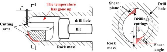
By studying the detection of the drilling process, the mechanism and factors of heat generation during the interaction between the drill bit and coal and rock mass are analyzed. The influences of coal and rock mass stress, coal and rock mass strength, bit motion parameters and bit material parameters on bit temperature change were obtained qualitatively, which provides a basis for the quantitative study of the relationship between the stress of coal and rock mass and the rate of bit temperature change.
(2).
On the basis of the mechanical analysis of the bit during drilling and the principle of energy conservation and thermal energy conversion theory, the conditional model of bit temperature rise and the coal stress identification model were established, and a linear expression between the coal stress and the bit temperature rate was obtained.
(3).
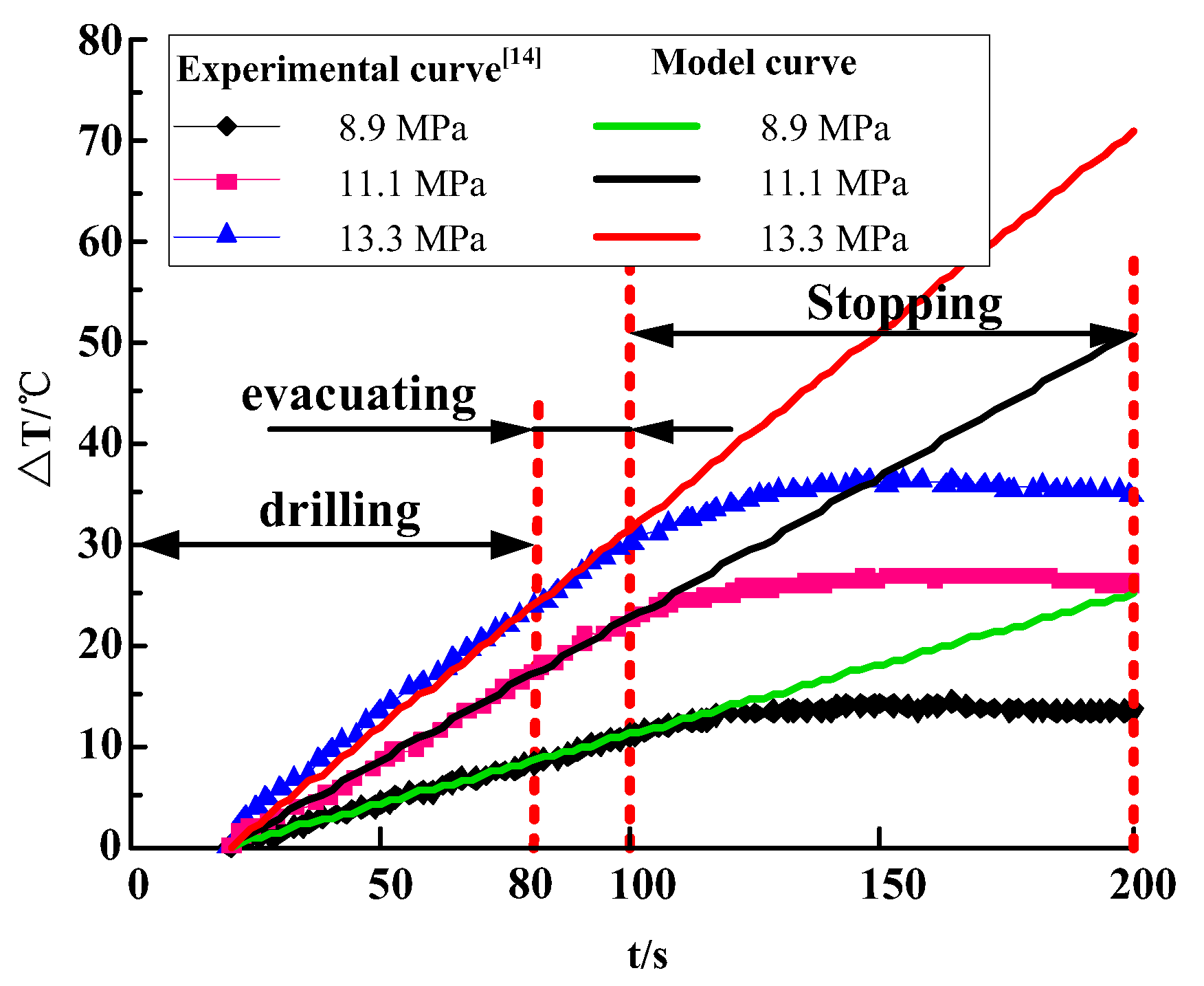
The variation law of bit temperature obtained from the stress identification model of the coal body is consistent with the experimental data, fully demonstrating the feasibility of using temperature as a discriminant stress index of coal. This provides a direct and effective reference for delineating dangerous areas of rock burst and testing the effect of anti-outburst measures.
(4).
In the process of using the bit temperature rate as the index to judge the coal stress value, a theoretical research method was adopted. The research results are preliminary and need to be further revised and deepened by practical application under specific engineering conditions.

Author Contributions

Conceptualization, P.Q. and X.L.; methodology, P.Q. and J.N.; validation, J.W., S.Y.

Funding

This research was funded by National Key R&D Program of China, grant number 2018YFC0604703; National Natural Science Foundation of China, grant number 51574154, 51904163; Major Program of Shandong Province Natural Science Foundation, grant number ZR2018ZA0603; Key R & D programs of Shandong Province, grant number 2018GSF116003; SDUST Graduate Student Technology Innovation Project, grant number SDKDYC190116; Youth Fund of Shandong Natural Science Foundation, grant number ZR2019QEE002; The authors express sincere thanks to the reviewers for their helpful comments and suggestions for improving this paper.

Conflicts of Interest

The authors declare no conflict of interest.

References

  1. Wang, H.T.; Xian, X.F.; He, J.M.; Lv, Y.C.; Ji, R.S.; Zhang, J.G. Inquisition of Forecasting Dangerousness of Heading Face Outburst by Drillings and Coalbed Temperature Indices. J. Chongqing Univ. (Nat. Sci. Ed.) 1999, 22, 34–38. [Google Scholar]
  2. Liu, S.W.; Fu, M.; Jia, H.S.; Li, W.B.; Luo, Y.F. Numerical simulation and analysis of drill rods vibration during roof bolt hole drilling in underground mines. Int. J. Min. Sci. Technol. 2018, 28, 877–884. [Google Scholar] [CrossRef]
  3. Liu, S.W.; Zhu, Q.K.; Jia, H.S.; Zhu, X.T. Characteristics and recognition of the dynamic response of strata interfaces to anchorage hole drilling in coal roadway roof. J. Min. Saf. Eng. 2017, 34, 748–753, 759. [Google Scholar]
  4. Liu, S.W.; Liu, D.L.; Feng, Y.L.; Li, X.T.; Shang, P.X. Influence of stress states on drilling velocity of anchorage hole on coal roadway roof. J. China Coal Soc. 2014, 39, 608–613. [Google Scholar]
  5. Liu, S.W.; Luo, Y.F.; Jia, H.S. Energy response characteristics of rock interface under drilling of roof anchorage borehole in coal roadway. J. China Univ. Min. Technol. 2018, 47, 88–96. [Google Scholar]
  6. Eunhye, K.; Kerwin, H.; Demetryus, O.; Andrew, K. Effects of the skew angle of conical bits on bit temperature, bit wear, and rock cutting performance. Int. J. Rock Mech. Min. Sci. 2017, 100, 263–268. [Google Scholar]
  7. Sajjad, K.; Alireza, B.; Hamid, H. An analytical model for estimating rock strength parameters from smallscale drilling data. J. Rock Mech. Geotech. Eng. 2019, 11, 135–145. [Google Scholar]
  8. Feng, Y.L.; Liu, D.L. Model Test on Dynamic Response Characteristics in Drilling Anchorage Borehole of Roadway Roof. Chin. J. Undergr. Sp. Eng. 2016, 12, 525–531. [Google Scholar]
  9. Feng, Y.L.; Liu, D.L.; Luo, Y.F. Experimental study on dynamic response characteristics in drilling sedimentary rocks of coal roadway roof. J. Saf. Sci. Technol. 2016, 12, 31–37. [Google Scholar]
  10. Yang, X.F.; Kang, Y.; Wang, X.C. Analytical dynamic model of the drill bit in rock drilling. J. China Coal Soc. 2012, 37, 1596–1600. [Google Scholar]
  11. Yang, X.F.; LI, X.H.; Lu, Y.Y. Temperature analysis of drill bit in rock drilling. J. Central South Univ. (Sci. Technol.) 2011, 42, 3164–3169. [Google Scholar]
  12. Jurij, S.; Primoz, M.; Mitja, P.; Goran, V.; Zeljko, V. The characterization of wear in roller cone drill bit by rock material—Sandstone. J. Petroleum Sci. Eng. 2019, 173, 1355–1367. [Google Scholar]
  13. Alexander, M.; Elena, S.; Llya, N. Choice of lubricating and cooling action of cutting fluids by the thermomechanical model. Adv. Mater. Res. 2014, 1036, 405–410. [Google Scholar]
  14. Pan, Y.S.; Xv, L.M.; Li, G.Z.; Li, Z.H. Experimental study on the effect of coal intensity on drillings temperature. J. China Coal Soc. 2012, 37, 463–466. [Google Scholar]
  15. Pan, Y.S.; Xv, L.M. Experimental investigation on temperature of drilling cuttings to predict rock burst. Chin. J. Geotech. Eng. 2012, 34, 2228–2232. [Google Scholar]
  16. Xu, L.M.; Li, Q.; Pan, Y.S.; Li, Z.H.; Li, G.Z.; Ma, X. Study on forecasting rock burst of the drill pipe torque method. Eng. Mech. 2014, 31, 251–256. [Google Scholar]
  17. Pradeep, L.M.; Michael, R.L.; Ilya, V.A.; Jeen, S.L.; Higgs, C.F. Studies on the formation of discontinuous chips during rock cutting using an explicit finite element model. Int. J. Adv. Manuf. Technol. 2014, 70, 635–648. [Google Scholar]
  18. Babak, A.; Stefan, M. The effects of chamfer and back rake angle on PDC cutters friction. J. Nat. Gas Sci. Eng. 2016, 35, 347–353. [Google Scholar]
  19. Xu, S.Q.; Tan, Z.Y. Numerical Simulation and Design Optimization of Expansive Soil Cutting Slope Reinforced by Bolt Frame Pier. Subgrade Eng. 2014, 175, 66–70. [Google Scholar]
  20. Zhou, Y.N.; Zhang, W.; Isaac, G.; Lin, J.S. Mechanical specific energy versus depth of cut in rock cutting and drilling. Int. J. Rock Mech. Min. Sci. 2017, 100, 287–297. [Google Scholar] [CrossRef]
  21. Munoz, H.; Taheri, A.; Chanda, E. Rock cutting characteristics on soft-to-hard rocks under different cutter inclinations. Int. J. Rock Mech. Min. Sci. 2016, 87, 85–89. [Google Scholar] [CrossRef]
  22. AbuBakara, M.Z.; Buttb, I.A.; Majeedc, Y. Penetration Rate and Specific Energy Prediction of Rotary—Percussive Drills Using Drill Cuttings and Engineering Properties of Selected Rock Units. J. Min. Sci. 2018, 54, 270–284. [Google Scholar] [CrossRef]
  23. Chen, J.H.; Feng, Y.; Zeng, Y.J.; Han, Y.N.; Wang, Y.; Niu, C.C. Continuous rock drillability measurements using scratch tests. J. Pet. Sci. Eng. 2017, 159, 783–790. [Google Scholar] [CrossRef]
  24. Jerzy, R. Discrete element thermomechanical modelling of rock cutting with valuation of tool wear. Comput. Part. Mech. 2014, 1, 71–84. [Google Scholar]
  25. Ritto, T.G.; Escalante, M.R.; Rubens, S.; Rosales, M.B. Drill-string horizontal dynamics with uncertainty on the frictional force. J. Sound Vib. 2013, 332, 145–153. [Google Scholar] [CrossRef]
  26. Liu, W.; Zhao, J.; Nie, R.; Zeng, Y.; Xu, B.; Sun, X. A Full Coupled Thermal–Hydraulic–Chemical Model for Heterogeneity Rock Damage and Its Application in Predicting Water Inrush. Appl. Sci. 2019, 9, 2195. [Google Scholar] [CrossRef]
Figure 1. Diagram of the relationship between the rate of temperature change of the bit and the influencing factors.
Energies 12 04282 g001
Figure 2. A three-dimensional structural mechanical model of a bit.
Energies 12 04282 g002
Figure 3. The force state diagram of the cutting surface of a bit.
Energies 12 04282 g003
Figure 4. Schematic diagram of a bit invading rock.
Energies 12 04282 g004
Figure 5. A schematic diagram of the force of the end face of I-I.
Energies 12 04282 g005
Figure 6. The model of broken rock.
Energies 12 04282 g006
Figure 7. Diagram of the relationship between change rate of the bit temperature and the stress of the coal rock.
Energies 12 04282 g007
Figure 8. Temperature variation of the bit under different stress states.
Energies 12 04282 g008
Figure 9. Fitting diagram of temperature variation of bit.
Energies 12 04282 g009
Figure 10. The relationship between the change rate of the bit temperature and the stress of the coal body.
Energies 12 04282 g010

