Article

Nonlinear Analysis and Performance of Electret-Based Microcantilever Energy Harvesters

by
Bashar Hammad
1,
Hichem Abdelmoula
2,
Eihab Abdel-Rahman
3 and
Abdessattar Abdelkefi
4,*
1
Department of Mechanical and Maintenance Engineering, German Jordanian University, Amman 11180, Jordan
2
Gowell International, Houston, TX 77041, USA
3
Department of Systems Design Engineering, University of Waterloo, Waterloo, ON N2L 3G1, Canada
4
Department of Mechanical and Aerospace Engineering, New Mexico State University, Las Cruces, NM 88001, USA
*
Author to whom correspondence should be addressed.
Energies 2019, 12(22), 4249; https://doi.org/10.3390/en12224249
Submission received: 19 September 2019 / Revised: 25 October 2019 / Accepted: 1 November 2019 / Published: 7 November 2019
(This article belongs to the Special Issue Modeling and Analysis of Energy Harvesters)

Abstract

:
An energy harvester composed of a microcantilever beam with a tip mass and a fixed electrode covered with an electret layer is investigated when subject to an external harmonic base excitation. The tip mass and fixed electrode form a variable capacitor connected to a load resistance. A single-degree-of-freedom model, derived based on Newton’s and Kirshoff’s laws, shows that the tip mass displacement and charge in the variable capacitor are nonlinearly coupled. Analysis of the eigenvalue problem indicates the influence of the electret surface voltage and electrical load resistance on the harvester linear characteristics, namely the harvester coupled frequency and electromechanical damping. Then, the frequency–response curves are obtained numerically for a range of load resistance, electret voltage and base excitation amplitudes. A softening nonlinear effect is observed as a result of decreasing the load resistance and increasing the electret voltage. It is found that there is an optimal electret voltage with the highest harvested electrical power. Below this optimal value, the bandwidth is very small, whereas the bandwidth is large when the electret voltage is above this optimal value. In addition, it is noted that for a certain excitation frequency, the harvested power decreases or increases as a function of electrical load resistance when the coupled frequency is closer to short- or open-circuit frequency, respectively. However, when the coupled frequency is between the short-circuit and open-circuit frequencies, the harvested power has an optimal resistance with the highest power. Increasing the excitation amplitude to raise the harvested power could be accompanied with dynamic pull-in instability and/or softening behavior depending on the electrical load resistance and electret voltage. However, large softening behavior would prevent the pull-in instability, increase the level of the harvested power, and broaden the bandwidth. These observations give a deeper insight into the behavior of such energy harvesters and are of great importance to the designers of electrostatic energy harvesters.

Graphical Abstract

1. Introduction

Power generation for low-energy, portable and miniature equipment attracts wide attention due to its potential in wireless and remote sensing, mobile electronics, wearable health devices, independent assistive technology, and space and military applications [1]. Unused and lost power in almost all systems can be retrieved and used to operate such equipment. With the advancement of new technologies, it becomes viable to harvest power from ambient and aeroelastic vibrations [2,3,4,5,6], thermal energy [7,8], airflow [9,10,11,12], and ocean waves [13].
Common energy-harvesting techniques employ piezoelectric [14,15,16,17,18], electromagnetic [19,20,21,22,23], electrostatic [24,25,26,27], and hybrid [28] conversion principles according to the type of application [29]. Electrostatic mechanism has advantages over other mechanisms where it is possible to work at low frequency and wide bandwidth [30]. In addition, it can be fabricated in batches due to its compatibility to Si CMOS processes leading to relatively low cost. However, the electronic circuit that achieves power conversion is complicated and suffers from large losses [31]. To overcome this limit, electrostatic energy harvesters using electret (dielectric material with permanent polarization) have been fabricated and tested with different ambient vibration inputs, active surface areas, and electret potentials resulting in a wide range of output power [30].
After introducing the first electrostatic current generator with two half-disk electrets in 1978 [32], many energy-harvesting structures have been fabricated and tested using electrets. A small-scale axial 4-blade turbine energy harvester was built using a cylindrical converter located all around the turbine [9]. An airflow energy harvester using flutter phenomenon and two parallel flat electret-based electrodes to convert flow-induced movements into electricity was demonstrated in [33]. A vibration-based energy harvester was fabricated using silicon and investigated in [34]. It consists of gap-closing interdigited combs on two sides of a movable mass connected to fixed ends by springs. The whole surface is covered by a thin layer of electret, and the entire device is biased by charges in the electret layer on the movable electrode only. Two opposite-charged-electret energy harvesters for enhanced output performance were presented in [35,36]. The negatively and positively charged electret plates are located on the bottom and top of a disk mass attached to a middle plate by spiral beams that vibrates in out-of-plane direction. It attained maximum induced charges at both extremes when it reaches its highest and lowest positions. A cantilever-beam-based harvester with a proof mass at the free end was introduced in [31]. The lower face of the beam is metallized and works as the counter-electrode. The electret, patterned above the other electrode, is separated mechanically from the counter-electrode by an air gap.
A description of a compact harvester made of a brass mass with an electret film glued to it is fabricated in [37]. A ground electrode is separated from the electret by an air gap which has a thickness governed by the height of small stacks made of cellular polypropylene films. Furthermore, these stacks determine the elastic restoring force of the harvester and, hence, its resonance frequency. Another compact MEMS device comprises proof mass with groove pattern suspended by springs facing electret strips on the bottom surface is demonstrated in [38]. It harvests energy mainly from in-plane motion and has relatively a large motion of the proof mass within the compact design. An out-of-plane energy harvester made of base and resonator chips was tested in [39]. Two electret layers cover the resonator chip that contains a circular proof mass suspended by a spring ring in this chip. In [40], two designs of out-of-planes energy harvesters were fabricated and tested, with an electret layer being deposited on the bottom electrode. In the first design, the upper movable electrode consisted of a thin copper plate. In the second design, copper traces were sandwiched between two flexible printed circuit board layers of polyimide. In both designs, a thick copper plate stacked in the middle of the thin plate, and spacers between the upper and bottom electrodes defined the gap of the varying-capacitance harvesters.
Although building new energy harvester’s structures using electrets has momentum recently, linear modeling and operation are still dominant in studying such harvesters. However, the linear analysis does not efficiently capture the performance of vibratory-based energy harvesters, especially when inherent nonlinearity of electrostatic force and operation in off-resonance conditions are considered due to wide and variable ambient vibration spectrum. The difficulty of obtaining analytical expressions for nonlinear models forces researchers to use numerical simulation techniques to study the performance of these energy harvesters [31,35,40,41,42]. In [35], Tao et al. formulated a lumped single-degree-of-freedom (SDOF) nonlinear model describing the dynamics of the electret-based harvester that has a disk-shaped circular mass suspended by sets of parallel-spiral springs around it. Using state-space forms, they solved them numerically by the ODE45 solver in MATLAB, and observed nonlinear behaviors for large excitation, such as different bandwidths for up and down sweeps in excitation frequency. Similarly, Boisseau et al. [31] used a Simulink model to solve the dynamic problem numerically. In [41], an analytical tool is proposed to formulate coefficients of lumped-parameter models for electret-based energy harvesters without consideration of strong electric fields, but including fringing fields, parasitic capacitance, and proof mass displacement. These coefficients are validated using a finite element computational model with excellent agreement. Time-domain circuit simulations and numerical solvers (SPICE and MATLAB/Simulink) are employed to simulate the lumped-parameter model that is represented by equivalent electrical circuits, for different energy harvester configurations.
The two designs described in [40] were modeled as single-degree-of-freedom (SDOF) systems using Kirshoff’s and Newton’s laws. The authors of [40] built a numerical model using MATLAB/Simulink to simulate the performance of the coupled system of equations characterizing those designs, and indicated that an analytical solution is not possible. An analytical model that predicts the induced charge under small sinusoidal excitation, was presented in [43]. However, the nonlinear terms make it difficult to obtain an analytical solution, which forces the authors to approximate the sinusoidal function by a parabolic function. This approximation led to a closed-form expression that can predict power with high accuracy at peaks when compared to numerical simulations. In [44], a theoretical and numerical study of a microcantilever energy harvester, with full overlapping of electret and beam, was carried out by deriving a distributed-parameter model using Hamilton’s principle and then discretized using Galerkin procedure assuming that it works in vacuum to maximize energy harvested.
In this work, we expand the SDOF model described in [45] for an energy harvester made up of a microcantilever beam with a tip mass (working as a movable electrode) and a fixed electrode with an electret layer. The electret layer is patterned on the fixed electrode and separated from the tip mass by an air gap. The model that is proposed in this study considers the displacement of the tip mass and the charge induced in a variable capacitor (composed of the movable tip mass and the fixed electrode) due to base excitation. The model is derived using Kirshoff’s Voltage Law (KVL) in addition to Newton’s Second Law (N2L). The model accounts for mechanical and electric nonlinearities due to moderately large deflections and the electrostatic force, as well as the coupling between them, thereby allowing an easier understanding of their effects and the interaction between these fields. The governing system of coupled equations of the electrostatic energy harvester derived in this model is solved numerically. The remainder of the study is organized as follows: Section 2 shows the derivation of SDOF charge-based model, static and dynamic analyses and the eigenvalue problem of the model, Section 3 discusses the performance of the electrostatic energy harvester for a variety of operating conditions and electrical load resistances, and Section 4 summarizes the main findings and conclusions of this work.

2. Problem Formulation

2.1. Single-Degree-of-Freedom (SDOF) Model

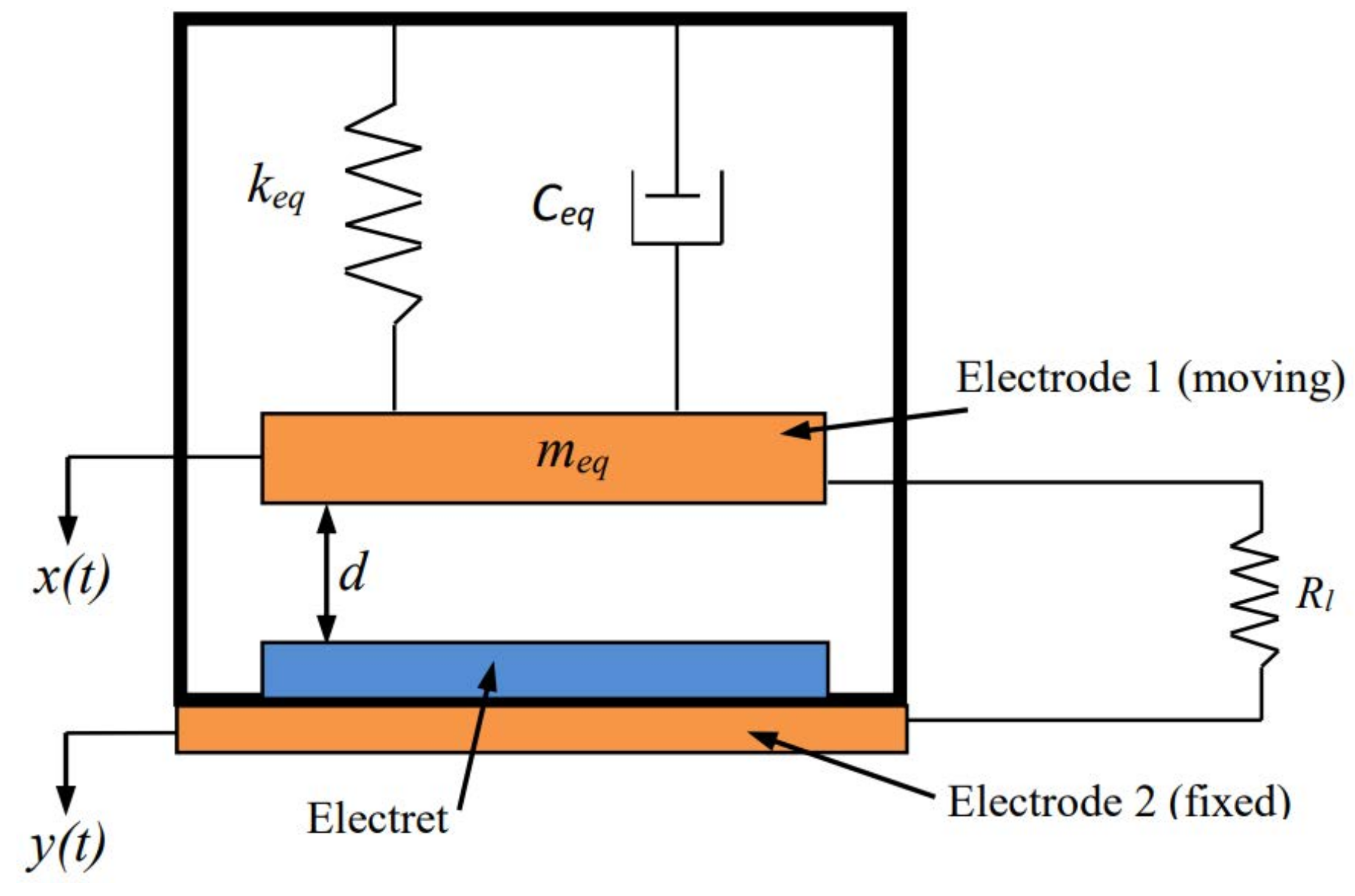
The energy harvester under consideration consists of a fixed electrode and a microcantilever beam supporting a tip mass forming a movable electrode, as shown in Figure 1. An electret layer is placed between the electrodes allowing the generation of quasi-permanent dipole polarization. The tip mass and the fixed electrode form a parallel-plate capacitor with air as dielectric separator. Electret is one of the significant developments in implementing electrostatic energy harvester to keep the electrical charge of the converter through time. Electrets are dielectric materials that maintain an electric field and a surface voltage for long time (it can reach years) due to charge trapping. Corona discharge is the most common technique to manufacture electrets, where a point-grid-plane structure is subjected to a strong electric field resulting in implanting electrical charges at the dielectric material. Based on the grid, the electret is charged to a designated surface voltage value. This value can be in thousands of volts. One of the commercially available electrets is Teflon® that has been used in many electret-based energy harvesters found in the literature [31]. The electret has a constant electrical charge, and the total summation of electrical charges on the electrode and on the counter-electrode equals the charge on the electret because of charge conservation and electrostatic induction.
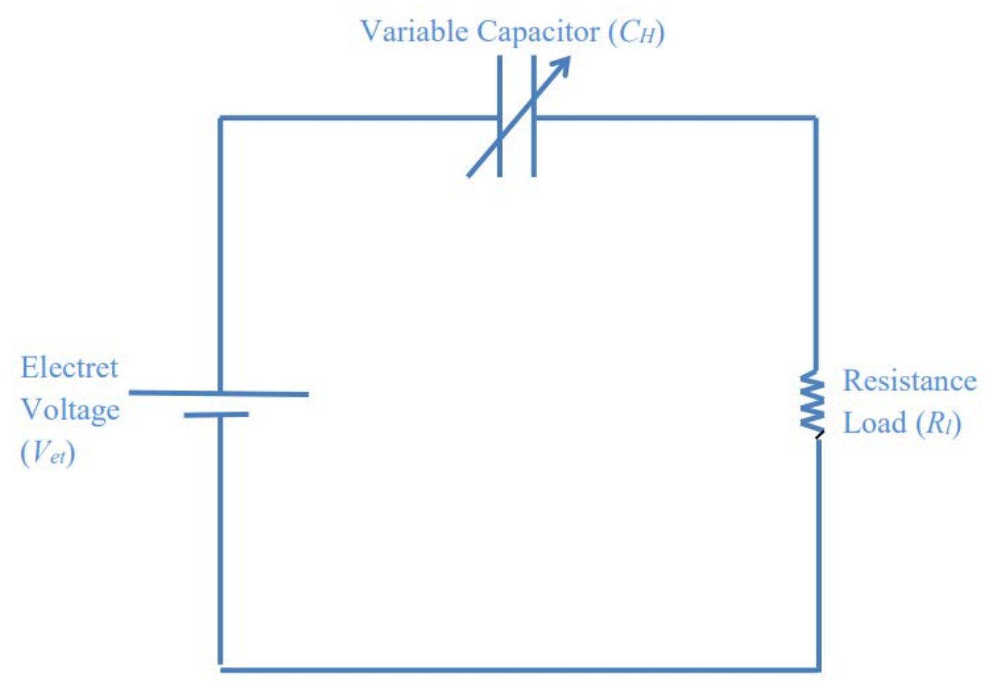
When the harvester is subjected to external vibrations, the cantilever beam oscillates with respect to the fixed electrode, thereby varying the capacitance of the capacitor. In other words, when the harvesting system is subjected to vibrations, the cantilever (counter-electrode) moves away from the electret changing the capacitance of the harvester, and a re-distribution of the electrical charges between the fixed electrode and the cantilever via the electrical load resistance occurs. The resulting voltage of the capacitor depends on the surface voltage of the electret, excitation amplitude and frequency (base excitation), and electrical load resistance, making reaching hundreds of volts possible and realistic as will be seen in the results. To harvest energy, a load resistance is electrically connected to the variable capacitor plates. This harvester can be modeled electrically by the circuit shown in Figure 2, where V e t is a static (DC) voltage source generated by the constant polarization of the electret layer, C H is a time-varying capacitor, and R l is a load resistance. By allowing the capacitance of the parallel-plate capacitor to vary over time in response to external vibrations, an AC voltage develops across C H and, consequently, an AC current, passes through R l causing power dissipation, which is harvesting energy. The tip mass (or proof mass) is attached to the cantilever beam to decrease its natural frequency. This tip mass changes the dynamics of the microcantilever because of its inertia. When the tip mass is much larger than the mass of the cantilever beam, a simple SDOF model can be adopted for the energy harvester [46]. Figure 3 shows a schematic diagram of the SDOF model of the electret-based microcantilever energy harvester considered in this work.
Newton’s Second Law (N2L) and Kirshoff’s Voltage Law (KVL) are used to formulate the governing equations of motion describing the response of the electrostatic energy harvester to a base excitation. Based on the schematic for the SDOF model of the microcantilever energy harvester shown in Figure 3, the governing equation based on Newton’s Second Law can be written as:
m e q z ¨ ( t ) = F e s ( t ) c e q z ˙ ( t ) k e q z ( t ) + m e q g m e q y ¨ ( t )
where z ( t ) is the relative deflection between the absolute motion x ( t ) of the equivalent mass m e q and the absolute motion of the base y ( t ) , i.e., it is the distance between the two electrodes, and hence expressed as:
z ( t ) = x ( t ) y ( t )
The equivalent mass of the harvester m e q is calculated by adding the tip mass M t to the equivalent mass of the cantilever beam at the free end m e q , c . Therefore,
m e q = m e q , c + M t
The term m e q , c is obtained using the equivalence of kinetic energy as explained in [46,47]. Based on derivation in [46,47], m e q , c is given by:
m e q , c = 33 140 m L
where L is the beam length, m denotes the mass per unit length of the cantilever. Therefore, the term m e q is then expressed as:
m e q = 33 140 m L + M t
The equivalent stiffness k e q is given by:
k e q = 3 E I L 3
where E denotes the Young’s modulus and I is the second moment of beam cross section area. The equivalent mechanical damping in the harvester is modeled as linear viscous damping and denoted as c e q . The constant g is the gravitational acceleration and taken as 9.81 m/s 2 . It is assumed that the base excitation is harmonic and can be expressed as:
y ( t ) = Y o cos ( Ω t )
where Y o and Ω are the amplitude and frequency of the base vibration, respectively. Consequently, the base acceleration is given by:
y ¨ ( t ) = Y o Ω 2 cos ( Ω t )
The electrostatic force F e s between the capacitor plates is given by [36]:
F e s = z q 2 ( t ) 2 C H
where q ( t ) represents the charge stored in C H . To model C H , the effective gap between the electrodes, g e , is defined as:
g e = g a + d e t ϵ e t
where g a denotes the air gap between the electret and the upper electrode (i.e., tip mass), ϵ e t is the permittivity of the electret, and d e t represents the electret thickness. Therefore, C H is expressed as follows:
C H ( z ( t ) ) = ϵ A g e z ( t ) = C e 1 z ( t ) g e
where ϵ is the permittivity of vacuum (= 8.854 × 10 12 F / m), A is the overlapping area, and C e denotes the effective capacitance which can be expressed as:
C e = ϵ A g e
Substituting Equation (11) into (9) yields,
F e s = q 2 ( t ) 2 g e C e
The second governing equation is derived based on Kirshoff’s Voltage Law. Applying this law to the equivalent circuit of the microcantilever electret energy harvester shown in Figure 2 results in:
V e t = V C H ( q ( t ) , z ( t ) ) + V R l
where V R l represents the voltage across the load resistance R l and is given by the well-known expression V R l = i R l where i denotes the current passing through the load resistance R l . Rearranging the above equation and substituting i = q ˙ ( t ) gives:
R l q ˙ ( t ) = V e t V C H ( q ( t ) , z ( t ) )
The voltage across C H is a function of the relative deflection between its plates and the charge on them and is given by:
V C H ( q ( t ) , z ( t ) ) = q ( t ) C H ( z ( t ) )
Substituting Equation (11) into Equation (16) yields:
V C H = q C e 1 z g e
Substituting Equations (8) and (13) into Equation (1), and Equation (17) into Equation (15) results in the following two coupled governing equations of motion:
m e q z ¨ + c e q z ˙ + k e q z = q 2 2 g e C e + m e q g + m e q Y o Ω 2 cos ( Ω t )
R l q ˙ + 1 C e q = V e t + 1 g e C e q z
Rearranging the above two equations yields:
z ¨ + 2 ζ ω n z ˙ + ω n 2 z = 1 2 η c q 2 + g + Y o Ω 2 cos ( Ω t )
q ˙ + ω e q = V e t R l + ω e g e q z
where ω n 2 = k e q / m e q represents the natural frequency of the mechanical oscillator, 1 / ω e = C e R l is the time constant of the electrical circuit, η c = ( m e q C e g e ) 1 denotes the electromechanical coupling coefficient, and ζ is the damping ratio. The governing differential equations of the energy harvester, Equations (20) and (21), are nonlinearly coupled via the relative deflection z and charge q.

2.2. Static, Dynamic and Eigenvalue Problems

Before studying the nonlinear response and investigating the performance of the energy harvester under investigation, static and linear analyses are carried out to determine the effect of the electret voltage on the harvester stability and characteristics. Starting with a static analysis, the time dependent terms in Equations (20) and (21) are dropped, and hence the following two algebraic equations for the static problem are obtained:
ω n 2 z s t = 1 2 η c q s t 2 + g
ω e q s t = V e t R l + ω e g e q s t z s t
where z s t and q s t are the deflection and electric charge at static equilibrium, respectively.
To shift the deflection and electric charge at static equilibrium to the origin, the following linear transformation is introduced:
u 1 = z z s t , u 2 = u ˙ 1 , u 3 = q q s t
Substituting the previous forms into Equations (20) and (21) and using Equations (22) and (23), one obtains:
u ˙ 1 = u 2
u ˙ 2 = ω n 2 u 1 2 ζ ω n u 2 + 1 2 η c u 3 2 + q s t η c u 3 + Y o Ω 2 cos ( Ω t )
u ˙ 3 = ω e u 3 + ω e g e ( u 1 u 3 + q s t u 1 + z s t u 3 )
As for the harvested power, it is given by [30,31]:
P = R l q ˙ 2
Substituting Equations (24) and (27) in the above equation, we obtain
P = R l [ ω e u 3 + ω e g e ( u 1 u 3 + q s t u 1 + z s t u 3 ) ] 2
The coupled (global) frequency is one of the main factors that affects the dynamics of electrostatically actuated systems. In addition, the coupled electromechanical damping help interpret the behavior of the electrostatic energy harvester under a variety of operating conditions. To determine the impacts of different parameters on the coupled frequency and electromechanical damping of the energy harvester under consideration, a linear analysis is performed by defining the following state variables of the system of Equations (25)–(27):
U = u 1 u 2 u 3
where u i are as defined in the linear transformation, Equation (24). Then, the linear reduced-order model of the harvester can be written as:
U ˙ = B U
where
B = 0 1 0 ω n 2 2 ζ ω n q s t η c ω e g e q s t 0 ω e + ω e g e z s t
After determining the general expressions for the equations of motion for the static, linear, and nonlinear scenarios, a deep investigation on the effects of the load resistance and the DC voltage on the pull-in instability, coupled frequency, electromechanical damping, and frequency–response curves of the energy harvester is carried out in the next section.

3. Electrostatic Energy Harvester Performance and Characteristics

Throughout this section, the model developed in this work is exploited to investigate the performance of the electret-based energy harvester fabricated and tested in [31]. The dimensions, specifications, and properties of this energy harvester are listed in Table 1. Although electrets have long lifetimes with almost constant surface voltage and charge due to negligible decay rate [48,49] ( V e t = 1400 V in this case [31]), we explore the performance of the harvester if other types with different voltage values are used. A smaller value of electret voltage of 400 V and a larger value of 2400 V are used in this investigation. In addition, it is worth mentioning that the damping ratio listed in Table 1 is the value of mechanical damping only. The electrical damping is determined based on the surface voltage of the electret and electrical load resistance. Mechanical and electrical damping values together determine the coupled damping of the harvester as shown later in this section. The mechanical damping ratio is selected to be very low ( ζ = 1/150) to simulate the underdamped response of the harvester and study the performance in absence of squeeze film damping effect. The length of the fixed electrode and the length of cantilever determine the overlapping area of the parallel-plate capacitor. The overlapping area between the fixed electrode and the cantilever is an independent parameter that can be selected according to the designer. In this work, the cantilever length is 30 mm and the fixed electrode length is 22.8 mm. This implies that the overlapping percentage is 76%, which is common in this field.
Based on the properties listed in Table 1, the tip mass is significantly larger than the mass of the cantilever itself. This justifies adopting the single-degree-of-free (SDOF) model as mentioned early in the paper [46,47].

3.1. Static Analysis and Pull-in Instability

It is important to determine the range of the static stability of the energy harvester to select operating points that are safely far from the pull-in conditions. It can be concluded from Equations (22) and (23) that the static equilibrium is dependent on the natural frequency of the mechanical oscillator ω n , reciprocal of time constant ω e , the electromechanical coupling coefficient η c , load resistance R l , the effective gap g e , DC electret voltage V e t , and gravitational acceleration g. This system of equations has three pairs of solutions for z s t and q s t ; one of these solutions is stable as long as no pull-in has occurred, the second solution is unstable, and the third solution is unphysical (larger than the dimension of the gap).
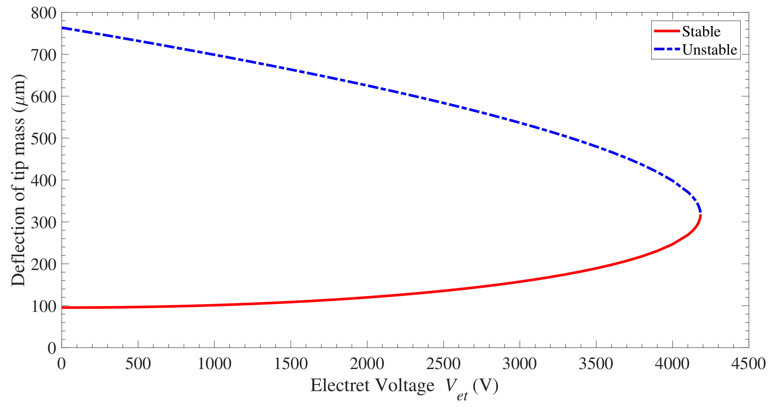
The stable solution (that represents the static deflection of the tip mass) and unstable solution are plotted against the electret surface voltage V e t and shown in Figure 4. The solid line represents the stable solution, whereas the dashed line represents the unstable solution. The third solution of the unphysical motion is not represented in this figure. As shown in Figure 4, the system is unstable in terms of displacement of tip mass in range of 318.2–763.5 μ m. In this unstable range, the electrostatic force between the electrodes becomes larger than the restoring force in the cantilever beam. This causes the attraction of the cantilever beam (the movable electrode) to the fixed electrode and, subsequently, the system collapses. This phenomenon is called static pull-in instability, and the voltage corresponds to the onset of this instability (deflection of 318.2 μ m) is called static pull-in voltage. Whenever the voltage is higher than the static pull-in voltage, the two electrodes snap together. The stable solution increases monotonically and nonlinearly with V e t until static pull-in occurs at 318.2 μ m when V e t = 4183.1 V for the dimensions and specifications listed in Table 1. It should be noted that the static pull-in deflection occurs at one third of the effective gap (obtained from Equation (10)) with considering the static deflection due to gravity. This static pull-in deflection agrees with the well-known fact that pull-in occurs at a deflection of one third of the gap for SDOF electrostatic actuators [50].

3.2. Coupled Frequency and Electromechanical Damping

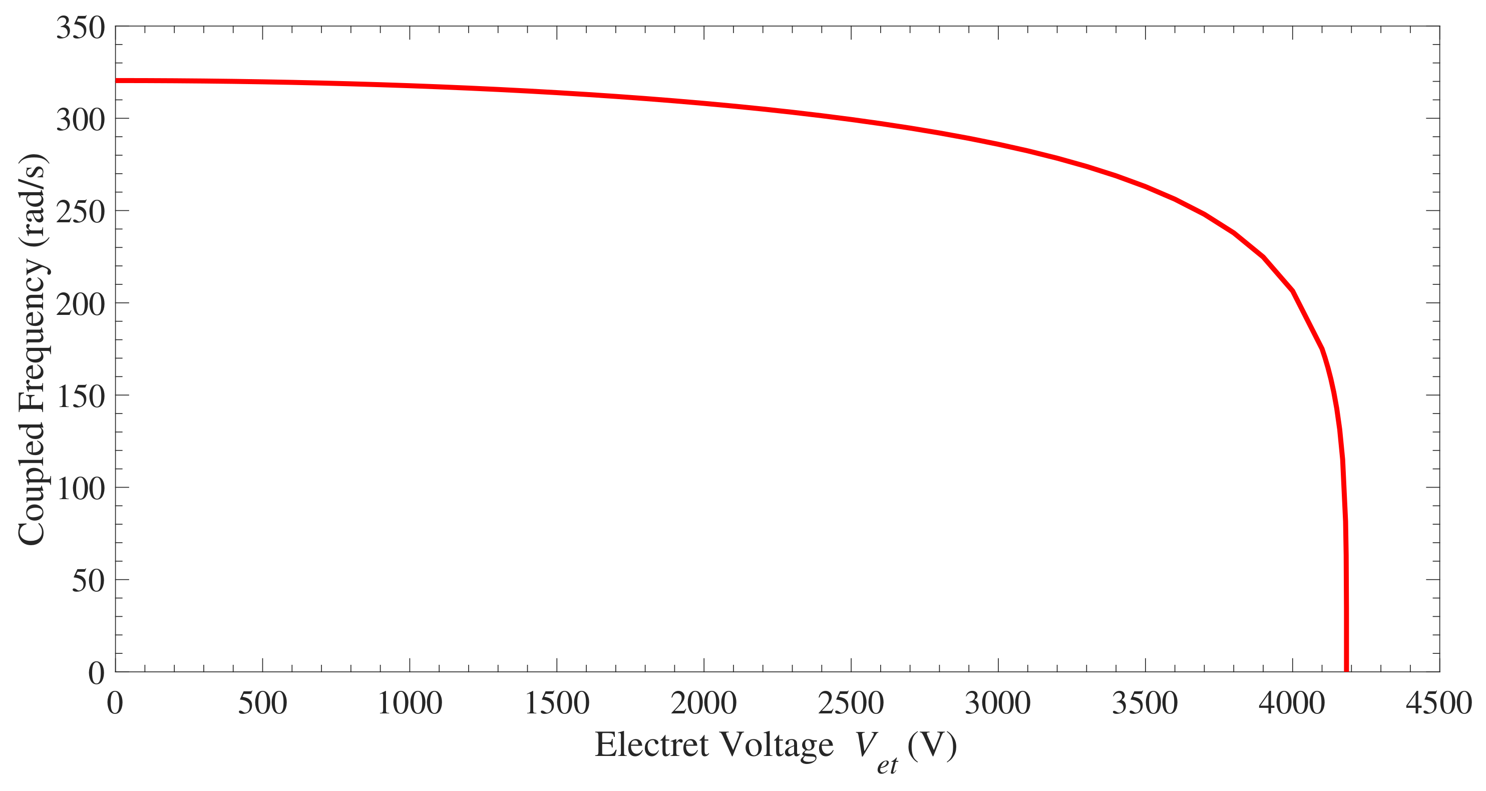
The matrix B obtained in Equation (32) has three eigenvalues. The first eigenvalue is always real and negative. The second and third eigenvalues are complex conjugates. The real part of the complex eigenvalues represents the electromechanical damping, and their positive imaginary part corresponds to the coupled frequency of the electromechanical system. Next, the influence of V e t and R l on the coupled frequency and electromechanical damping is investigated. The variation of the coupled frequency with V e t is shown in Figure 5. When V e t is equal to zero, i.e., the coupling terms between the mechanical and the electrical equation are vanished, the frequency is the same as the natural frequency of the mechanical oscillator ω n . As V e t increases, the coupled frequency decreases slightly until it drops drastically and becomes zero when V e t = 4183.1 V at pull-in instability, agreeing with the static deflection results reported in Figure 4. In summary, the coupled frequency is equal or smaller than ω n .
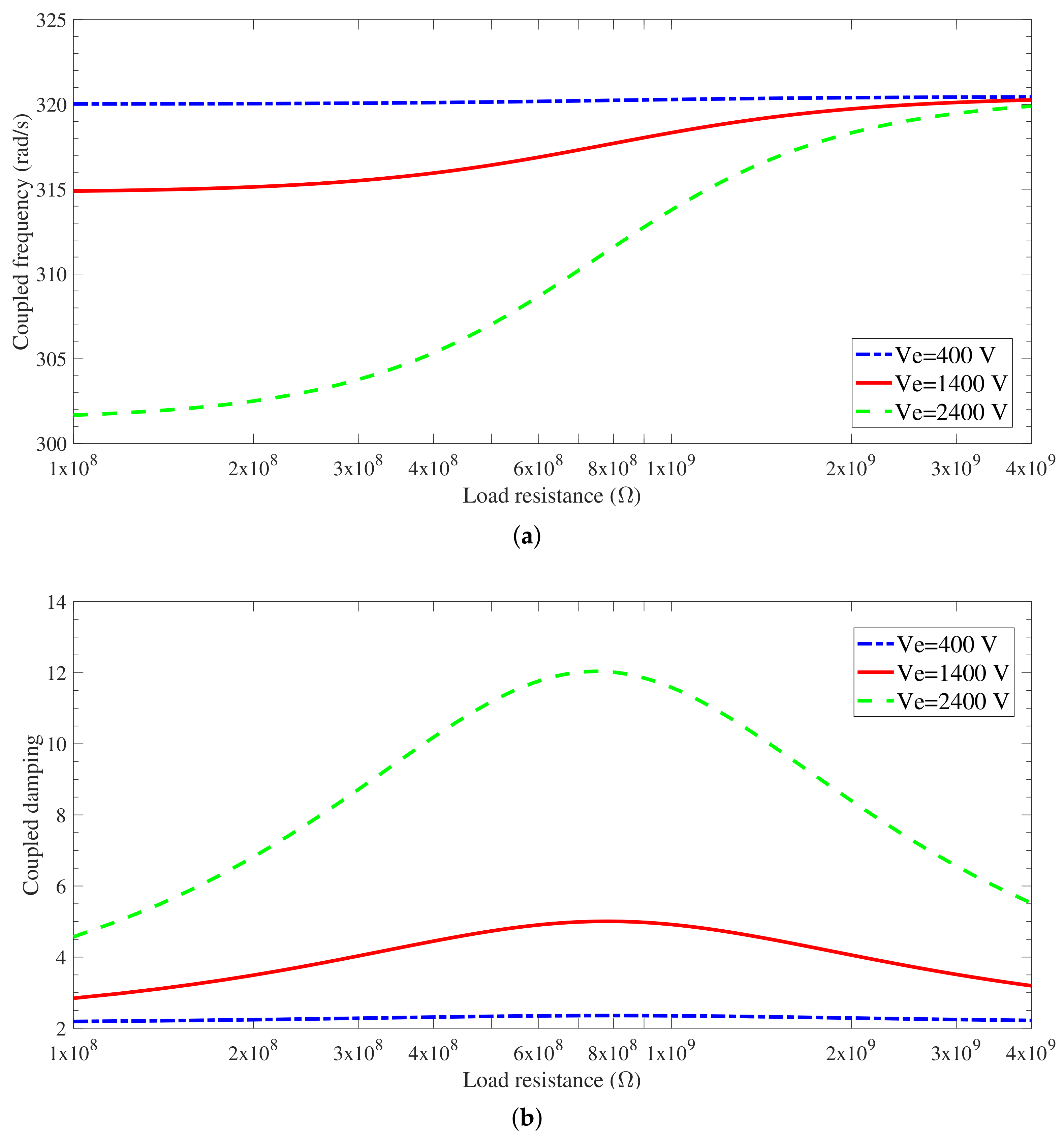
The variations of the coupled frequency and electromechanical damping as a function of the electrical load resistance R l for different values of V e t are shown in Figure 6a,b, respectively. For V e t = 400 V, the effect of R l on the coupled frequency and electromechanical damping is insignificant. However, for larger values of V e t ( V e t = 1400 V and 2400 V), the effect of R l on the coupled frequency is slight for large values of R l as noted in the upper range of R l in Figure 6a. Increasing R l further such that R l , the coupled frequency does not change and is called open-circuit coupled frequency, [51]. However, as R l decreases, the coupled frequency decreases noticeably. Further decrease in R l does not change the coupled frequency of the harvester as observed in the lower range of R l in Figure 6a. In other words, as we decrease R l for very small values, the coupled frequency does not change. The frequency as R l gets closer to 0 is called short-circuit coupled frequency. If Figure 6a is expanded such that the horizontal axis starts from R l = 0, the short-circuit coupled frequency can be determined. However, modifying the figure would not add significant values to that figure because the variations of coupled frequency as a function of R l would be straight lines for very small R l . In addition, as V e t increases for the same R l , the coupled frequency decreases, and this decrease becomes remarkable for small R l . This behavior can be explained by the increase of the attraction of the electrostatic force which affects the internal energy of the system. In case of the same V e t and changing R l , the coupled frequency is the same as ω n for very large R l . As R l gets smaller, the coupled frequency becomes smaller than ω n .
As will be seen in the frequency–response curves generated next, as the excitation frequency gets closer to the coupled frequency, the harvester becomes closer to resonance. In addition, we notice that ω e , which is the reciprocal of C e R l , decreases when R l increases (for the same V e t ), and hence the coupled frequency increases.
In Figure 6b, the electromechanical damping variation as a function of R l for different values of V e t is shown. Similar to the variation of the coupled frequency, the influence of R l on the electromechanical damping is not significant for the smallest voltage used in this investigation ( V e t = 400 V). However, as V e t increases, peaks of the electromechanical damping appear at approximately the same values of R l . The larger the electret voltage, the larger the electromechanical damping. However, as R l deviates from these peaks, the electromechanical damping decreases gradually, and the change becomes negligible for large and small values of R l .

3.3. Energy Harvester Performance and Nonlinear Characteristics

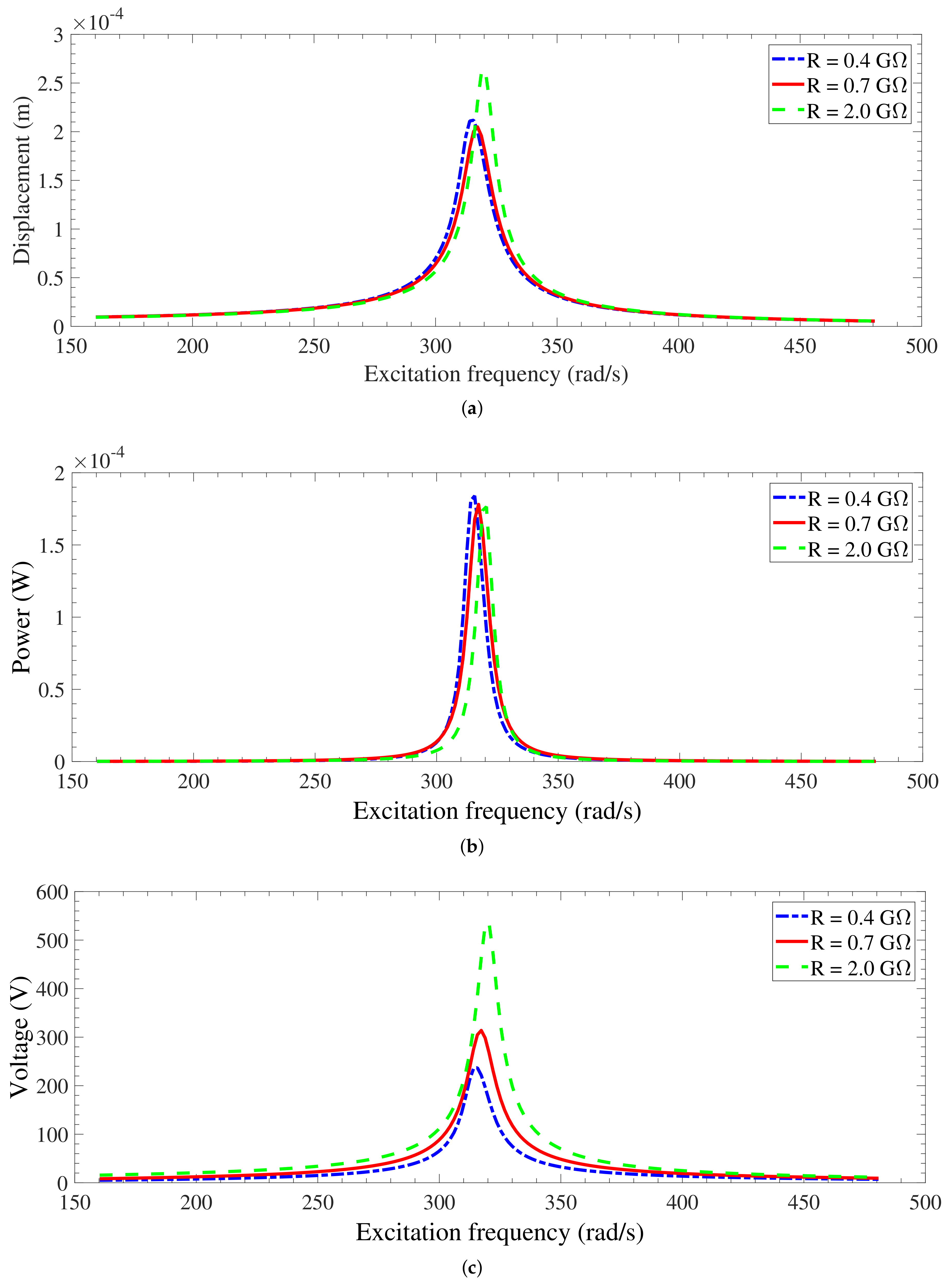
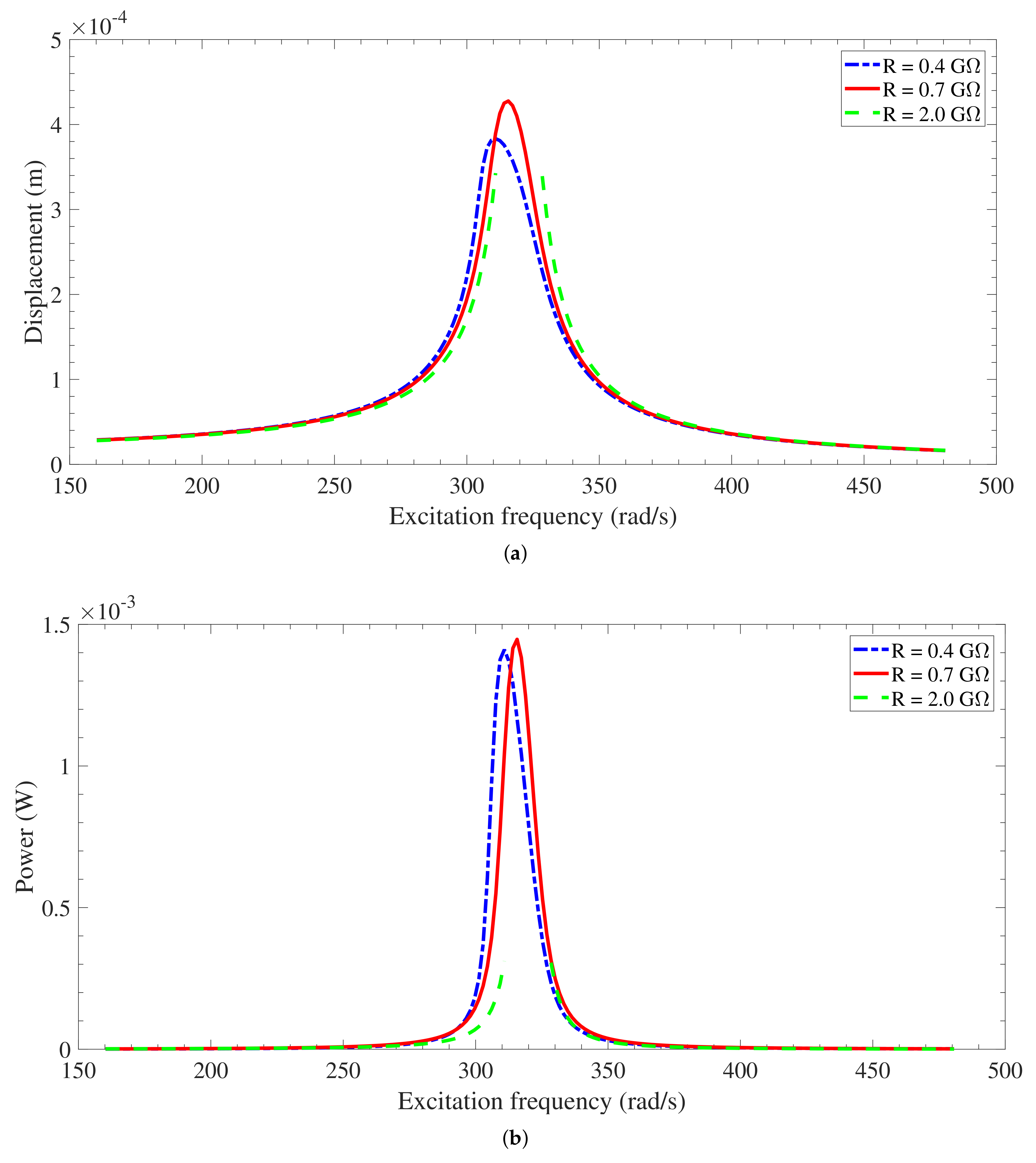
To investigate the performance and nonlinear behavior of the electrostatic energy harvester over a large range of excitation frequencies around the natural frequency of the electromechanical oscillator, the frequency–response curves for a variety of electrical load resistances R l , electret surface voltages V e t , and base accelerations Y o Ω 2 are plotted and discussed. The frequency–response curves in terms of root mean square (RMS) of displacement, electrical harvested power, and voltage across the load resistance for the case of V e t = 1400 V and forcing amplitude Y o Ω 2 of 1 m/s 2 are shown in Figure 7a–c. Inspecting these figures, it is noted that maximum values (resonant responses) occur at excitation frequencies corresponding to the coupled frequencies of the energy harvester, and these maximum values shift to smaller excitation frequencies as the electrical load resistance decreases, agreeing with the results for the coupled frequency reported in Figure 6a. Away from the resonant responses, the displacement, harvested power, and generated voltage decrease for all cases. Looking at the frequency–response curves of displacement in Figure 7a more closely reveals that the peak for R l = 2.0 G Ω is the largest and the peak for R l = 0.7 G Ω is the smallest. This is explained by referring to the electromechanical damping depicted in Figure 6b, where it has the smallest value for R l = 2.0 G Ω and the highest for R l = 0.7 G Ω . The maximum values of electrical harvested power for the three cases of R l demonstrated in Figure 7b are almost the same even though the maximum values of displacement, Figure 7a, are not equal. This is clarified by observing the frequency–response curves of voltage across the electrical load resistance, Figure 7c, where the generated voltage becomes larger for larger values of electrical load resistances. However, the effects of increasing both generated voltage across resistance and resistance itself on the electrical power are opposite as concluded from P = V 2 / R l . The interaction of increasing both voltage and resistance results in almost the same maximum values of electrical power for the parameters used in this investigation.

3.3.1. Effects of the electret surface voltages on the system performance

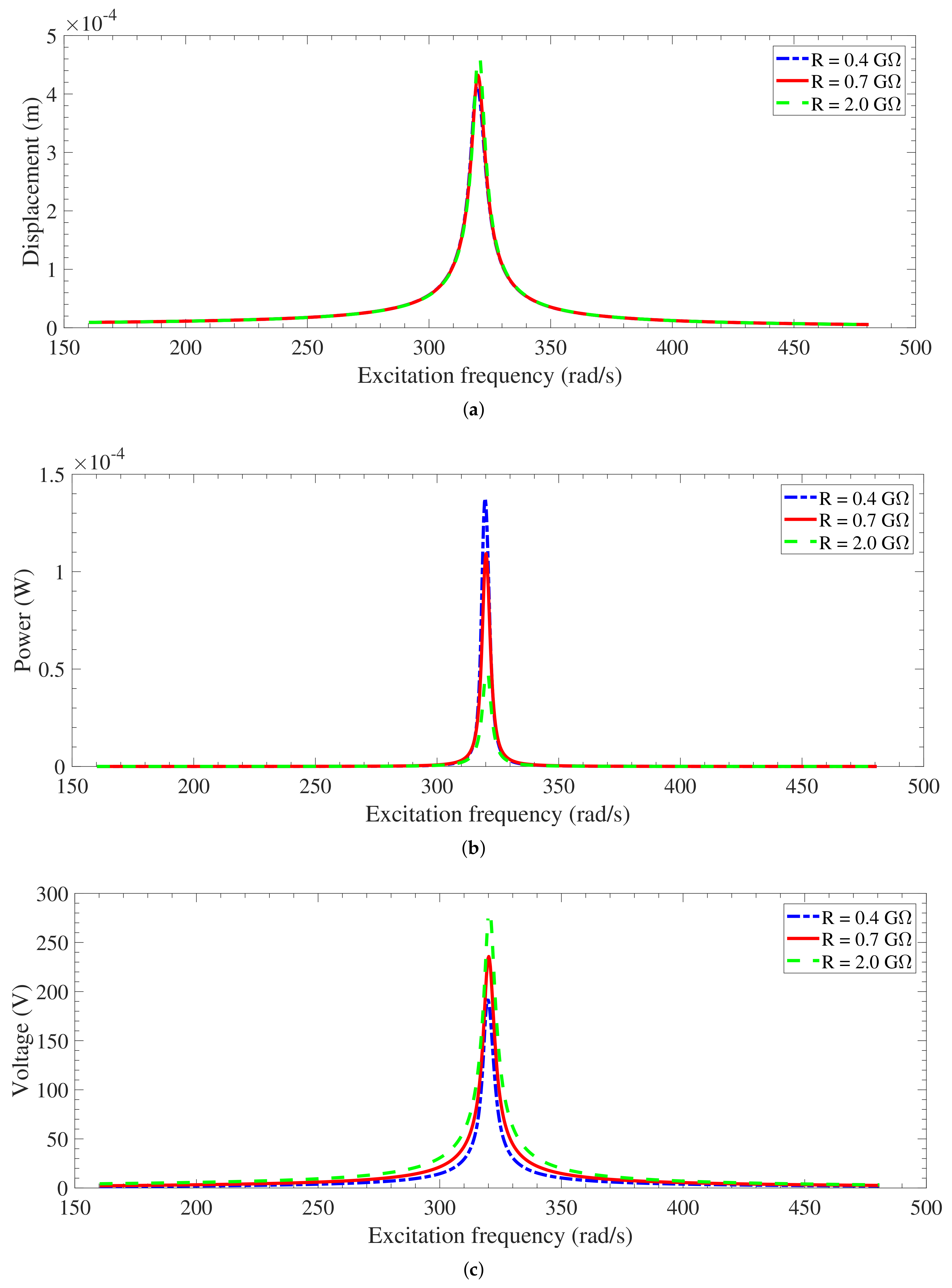
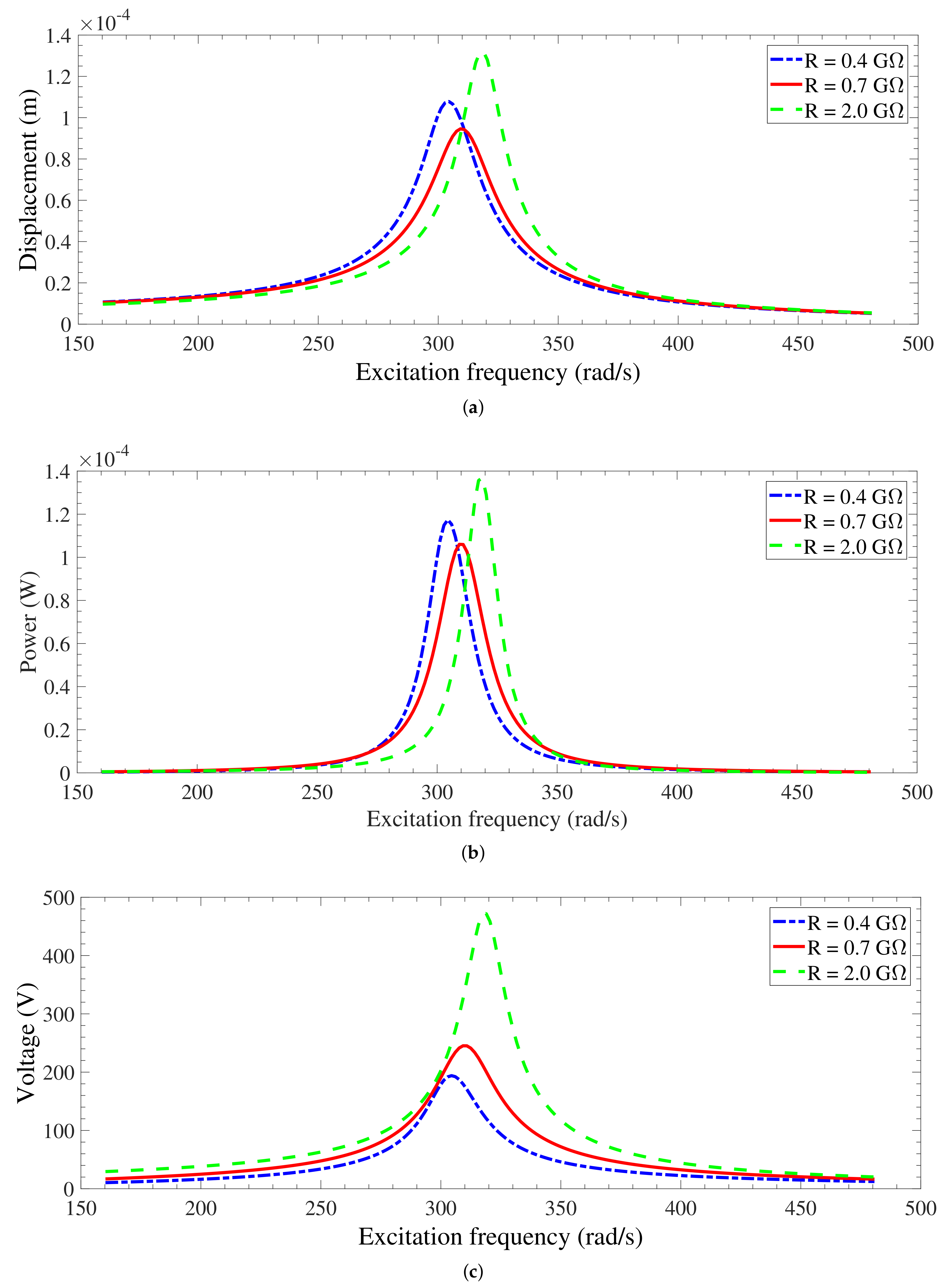
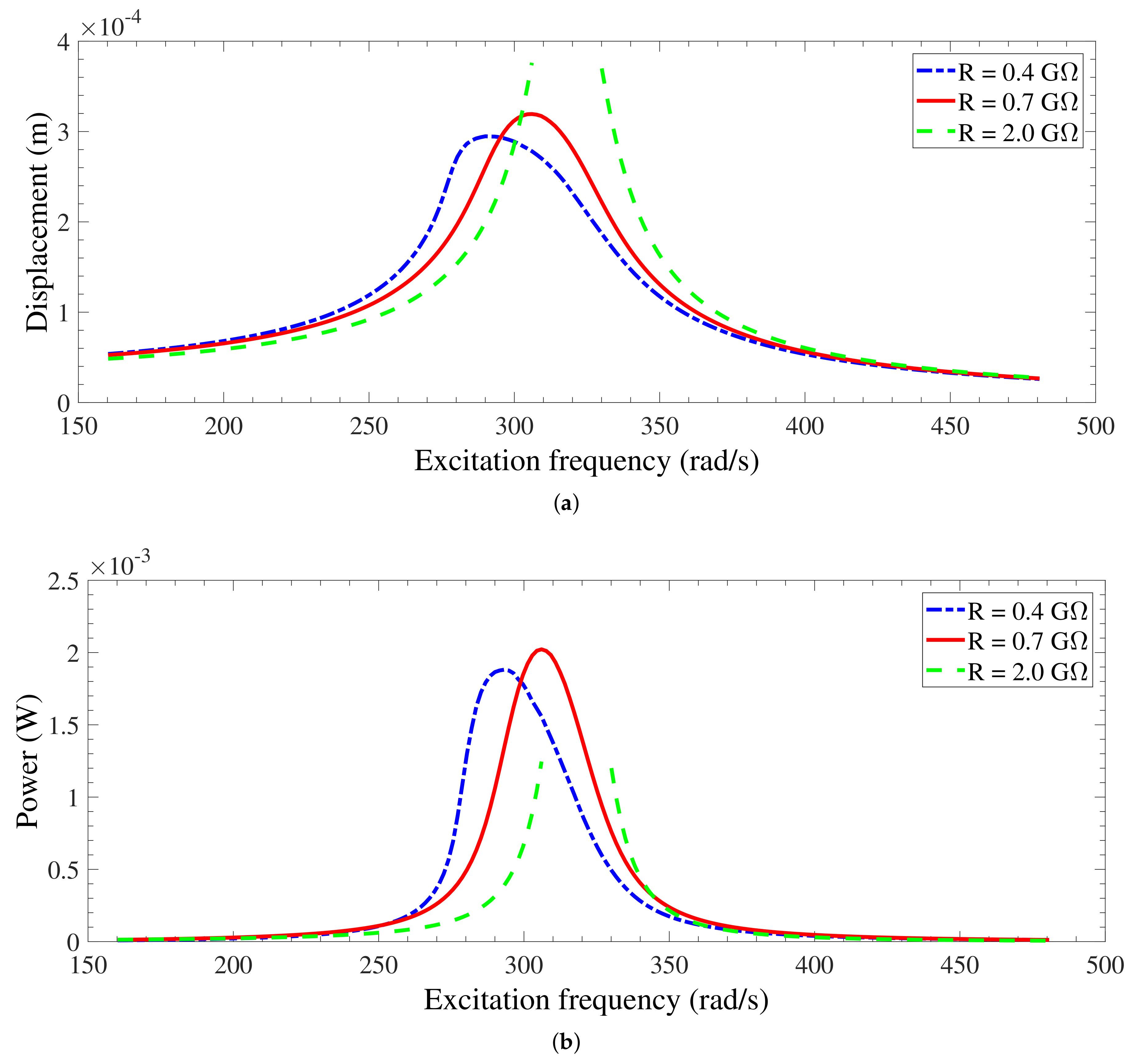
To study the impact of the electret surface voltages V e t , smaller and larger values of V e t compared to the case of V e t = 1400 V discussed in Figure 7 are considered. Figure 8 and Figure 9 show the frequency–response curves for V e t = 400 V and 2400 V, respectively. Because the effect of varying R l on the coupled frequency and electromechanical damping for V e t = 400 V is not significant as discussed in Figure 6a,b, the response is similar to linear (no resonance frequency shift) as demonstrated in Figure 8a–c. Decreasing V e t leads to a decrease in the generated voltage across the electrodes and absence of softening effect due to electret voltage. The displacement for R l = 0.4 G Ω and R l = 0.7 G Ω are close to each other, but the displacement for R l = 2.0 G Ω has a very small range of frequency around resonance frequency with a pull-in instability develops as shown in Figure 8a. This is attributed to the small V e t and large R l . However, the harvested power at the resonance frequency for R l = 0.4 G Ω is the highest, as indicated in Figure 8b, even though the voltage across R l = 0.4 G Ω is the lowest, as presented in Figure 8c. This is clarified by the same reasoning discussed above about the interaction of increasing both generated voltage and resistance on the harvested power. For V e t = 2400 V, the behavior of the displacement in Figure 9a is similar to that for V e t = 1400 V, as shown in Figure 7a. However, the harvested power is the highest for R l = 2.0 G Ω and it is the lowest for R l = 0.7 G Ω based on the interaction of increasing both generated voltage and resistance.
Comparing the behavior of the displacement for V e t = 1400 V, 400 V, and 2400 V as shown in Figure 7a, Figure 8a, and Figure 9a, respectively, it is observed that the displacement is the highest for V e t = 400 V and the lowest for V e t = 2400 V. This is due to the fact that electromechanical damping is the lowest for V e t = 400 V and the highest for V e t = 2400 V, as depicted in Figure 6b. The generated voltage for V e t = 1400 V, 400 V, and 2400 V as shown in Figure 7c, Figure 8c, and Figure 9c, respectively, has the same trend; it is the highest for the largest load resistance ( R l = 2.0 G Ω ) and the lowest for the smallest load resistance ( R l = 0.4 G Ω ). The harvested power in case of V e t = 1400 V is the largest as shown in Figure 7b compared to cases of V e t = 400 V and 2400 V as plotted in Figure 8b and Figure 9b, respectively. This is attributed to the optimal electrical load resistance that is investigated next. However, inspecting Figure 7b, Figure 8b, and Figure 9b, it is shown that as the electret surface voltage V e t increases, the bandwidth increases giving the chance to a larger range of frequencies at which the harvester can generate high levels of the electrical power.

3.3.2. Optimal Performance of the Energy Harvester

Figure 10 shows the variations of the harvested power as a function of the electrical load resistance for various excitation frequencies. For V e t = 1400 V, Figure 10a shows the harvested power variations for excitation frequencies very close to the resonant frequencies Ω = 315 rad/s, 317 rad/s, and 320 rad/s as concluded from Figure 7. It is noted that Ω = 315 and 320 rad/s are very close to the short- and open-circuit frequencies, respectively, as shown in Figure 6a, while Ω = 317 rad/s is between the short- and open-circuit frequencies. It is found that the harvested power decreases with increasing R l for Ω = 315 rad/s, while the power increases with increasing R l for Ω = 320 rad/s. For Ω = 317 rad/s, there is an optimal resistance value where the harvested power has a maximum value. Away from this optimal value (increasing or decreasing), the power decreases. For V e t = 2400 V, the variations of the harvested power versus R l for Ω = 304, 310, 318 rad/s (resonant frequencies in Figure 9) is shown in Figure 10b. Power decreases for Ω = 304 rad/s (close to short-circuit frequency) and increases for Ω = 318 rad/s (close to open-circuit frequency) as R l increases, whereas there is an optimal value for Ω = 310 rad/s. For the parameters used in this work, comparing the maximum harvested power for the three excitation frequencies, Figure 10a,b, and maximum power for the three electrical resistances, Figure 7b and Figure 9b, respectively, it is a found a perfect matching. In addition, a perfect matching is observed when the harvested power is compared in Figure 10a,b for a certain R l to the harvested power values given in Figure 7b and Figure 9b, respectively, for a certain excitation frequency. For V e t = 400 V, the variations of the harvested power versus R l for Ω = 320 rad/s (resonant frequency Figure 8) is shown in Figure 10c. As R l increases, power decreases until pull-in instability develops close to R l = 1.8 G Ω as noticed in Figure 10c showing a perfect matching with Figure 8b.

3.3.3. Base Acceleration Effects and Dynamic Pull-In

It is worth mentioning that for the case of base acceleration Y o Ω 2 of 1 m/s 2 discussed above, the displacement response of the harvester is linear or weak nonlinear for all cases of electrical load resistances R l and electret surface voltages V e t employed in this work. Because of this linear behavior of the harvester under these conditions, interpreting the results obtained in Figure 7a, Figure 8a, and Figure 9a based on the results of eigenvalue problem discussed in Section 3.2 in terms of coupled frequency and electromechanical damping, Figure 6a,b, is possible and reasonable. The effect of increasing the base acceleration Y o Ω 2 to 3 m/s 2 and 5 m/s 2 on the displacement and the electrical power of the harvester is studied next for the three cases discussed above; V e t = 400 V, 1400 V, and 2400 V. In general, as Y o Ω 2 increases, the displacement and harvested power increase. However, two phenomena—dynamic pull-in instability and softening behavior—may develop with an increase of Y o Ω 2 as investigated next.
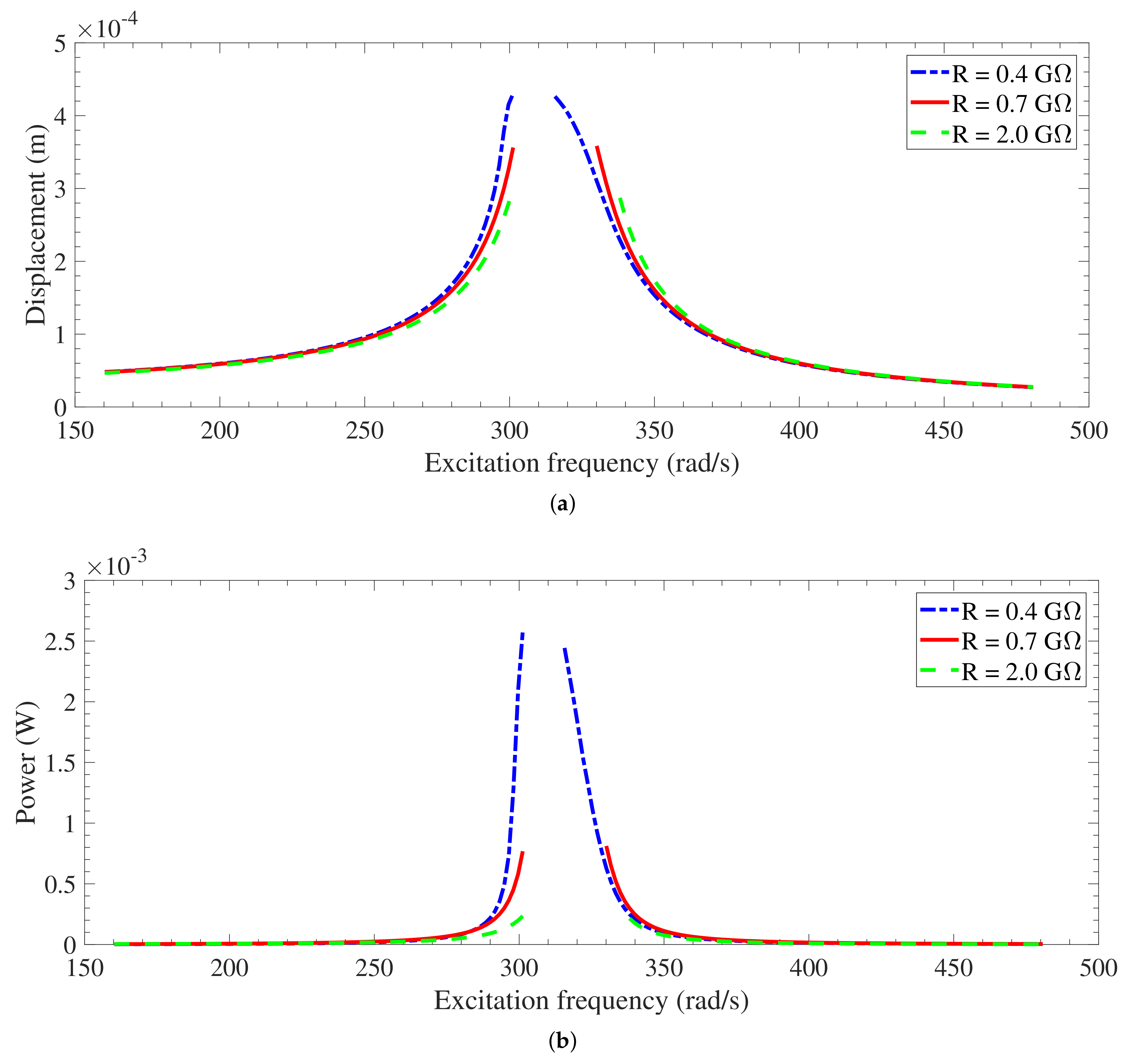
For the standard case of V e t = 1400 V, for Y o Ω 2 = 3 m/s 2 , different behaviors can be distinguished for the different values of R l , as depicted in Figure 11a,b. For the largest value used in this work ( R l = 2.0 G Ω ), it is observed that the forcing is large enough to develop a pull-in instability before softening effect and electromechanical damping create a limited response. The displacement response is limited for R l = 0.4 G Ω and R l = 0.7 G Ω . However, softening behavior is noted for R l = 0.4 G Ω as the frequency–response curve is bent to the left, and a linear behavior is still dominant for R l = 0.7 G Ω even with increasing the base acceleration. The harvested power response, Figure 11b, has the same trend as the displacement response shown in Figure 11a. While showing pull-in instability is important to report displacement behavior, reporting harvested power response is more important and common in the field of energy harvesters. This is the reason behind reporting power response (Figure 11b) even though they have the same trend as displacement behavior (Figure 11a). For the two limited responses of Y o Ω 2 = 3 m/s 2 , the displacement and harvested power are larger than these of Y o Ω 2 = 1 m/s 2 . Increasing the base acceleration to Y o Ω 2 = 5 m/s 2 , the response is unlimited for the three values of R l used in this work, as presented in Figure 12a,b. However, the dynamic pull-in instability for Y o Ω 2 = 5 m/s 2 develops at a wider range of excitation frequency compared to the range of Y o Ω 2 = 3 m/s 2 . In addition, the unlimited responses for the smallest R l (0.4 G Ω ) and R l = 0.7 G Ω show softening and linear behaviors, respectively, before the pull-in instability takes place.
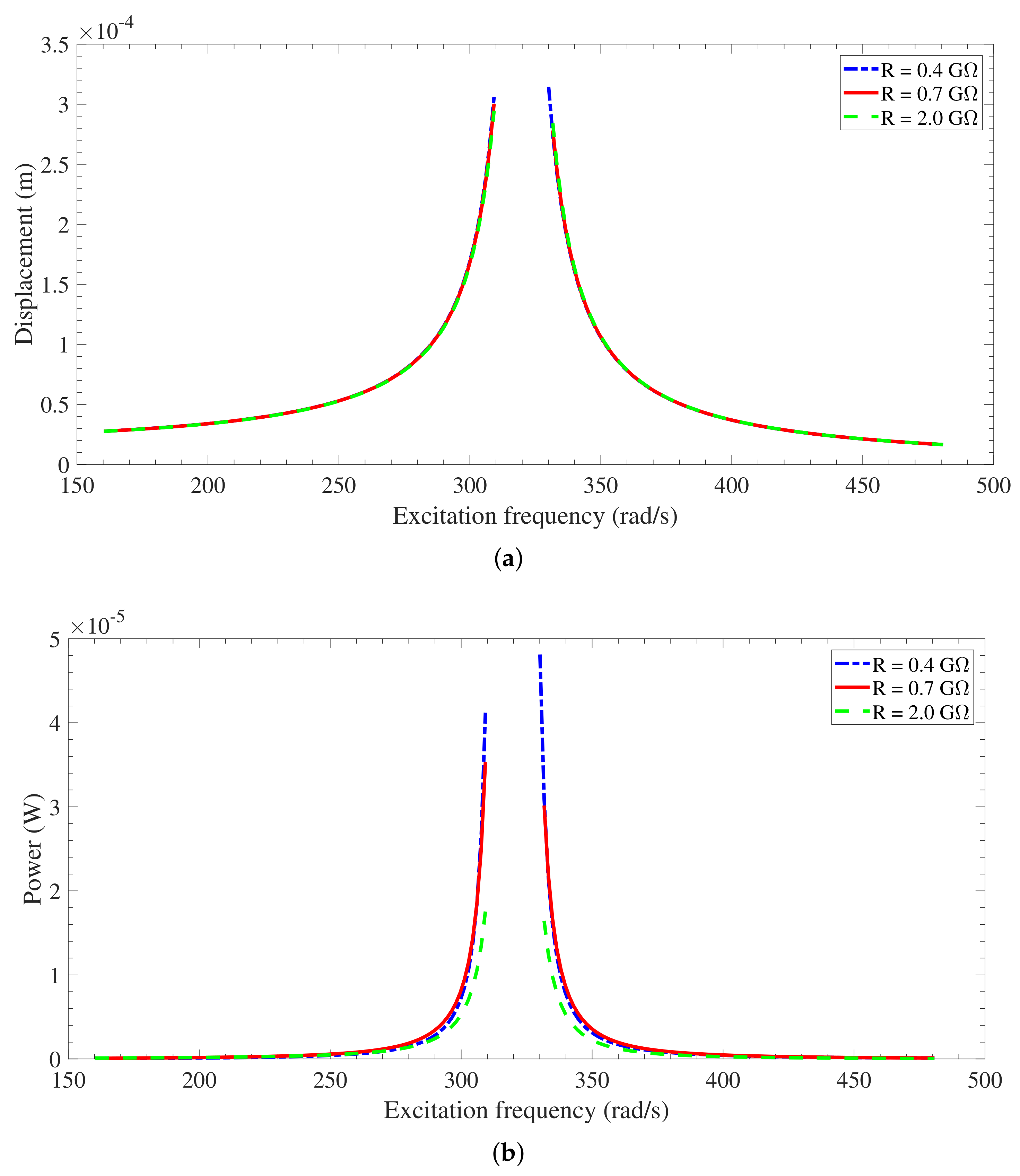
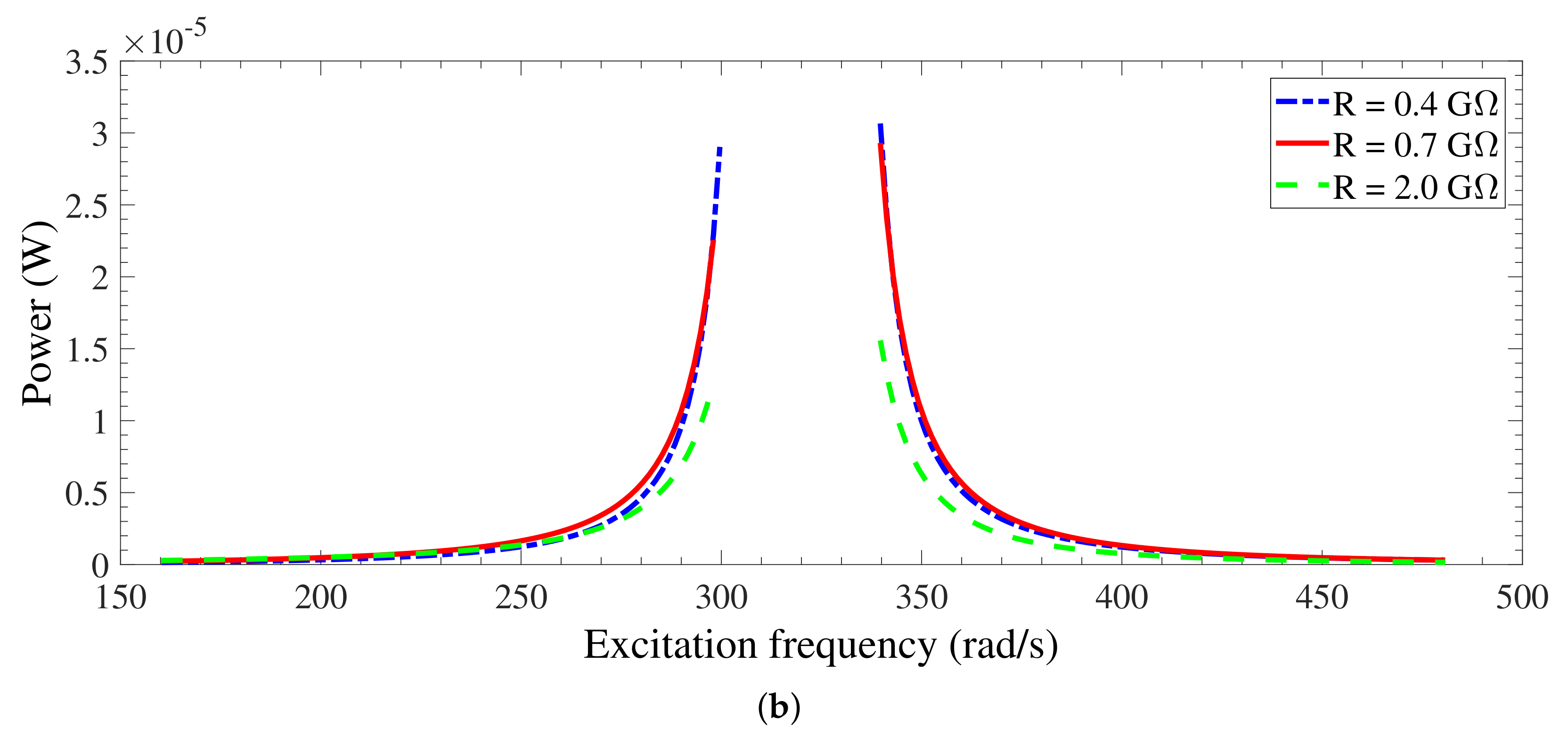
For the case of V e t = 400 V and Y o Ω 2 = 3 m/s 2 (shown in Figure 13) and 5 m/s 2 (shown in Figure 14), the response becomes unlimited for all the three cases of R l . Similar to the case of Y o Ω 2 = 1 m/s 2 and even with increasing Y o Ω 2 , the responses for all cases of R l are close to each other without having any softening behavior. However, as Y o Ω 2 increases for the case of V e t = 400 V, the range of excitation frequency where pull-in instability develops becomes broader. For the largest scenario used in this investigation ( V e t = 2400 V), the responses for all cases of R l are limited for Y o Ω 2 = 3 m/s 2 with linear behavior for large values of R l (0.7 and 2.0 G Ω ) but softening behavior for the smallest R l (0.4 G Ω ), as shown in Figure 15. Increasing Y o Ω 2 further to 5 m/s 2 , the response develops a dynamic pull-in instability for the largest R l (2.0 G Ω ), while it is still linear for R l = 0.7 G Ω and with softening behavior for the smallest R l (0.4 G Ω ), as shown in Figure 16. In Table 2, a summary of all unlimited-response cases described before with the boundaries of pull-in range. It is clear that for the same conditions, as Y o Ω 2 increases, the pull-in range becomes wider. Moreover, comparing the harvested power for cases of all limited responses (Figure 7b and Figure 11b for V e t = 400 and Figure 9b, Figure 15b, and Figure 16b for V e t = 2400 ), it is found that the bandwidth increases as Y o Ω 2 increases.
Inspecting the results shown above, it can be inferred that for the case of minimal softening ( V e t = 400 ), the responses are unlimited for all cases of R l (0.4, 0.7 and 2.0 G Ω ) as Y o Ω 2 increases to 3 and 5 m/s 2 . However, as softening effect is increased by using V e t = 1400 , the responses that are limited for all cases of R l when Y o Ω 2 = 1 m/s 2 becomes unlimited for R l with the lowest softening effect (2.0 G Ω ) when Y o Ω 2 = 3 m/s 2 and unlimited for all cases of R l when Y o Ω 2 = 5 m/s 2 . However, increasing the softening effect to the largest scenario used in this work ( V e t = 2400 ), the responses that are limited for all cases of R l when Y o Ω 2 = 1 m/s 2 stay limited when Y o Ω 2 is increased to 3 m/s 2 . Increasing Y o Ω 2 to 5 m/s 2 for the case of V e t = 2400 , the responses stay limited for R l = 0.4 and 0.7 G Ω , but the response for R l = 2.0 G Ω (lowest softening effect) becomes unlimited.
The above results obtained in this work showed that the effectiveness of electrostatic energy-harvesting, which is mainly due to the nonlinear coupling between the displacement and charge, increases for higher base acceleration and higher electret voltage due to introducing softening behavior to the harvester performance. This softening behavior delayed the pull-in instability, increased the level of the harvested power, and broadened the bandwidth.

4. Conclusions

This work investigated the behavior of an electret-based energy harvester subjected to an external harmonic base excitation. The harvester is made up of a microcantilever beam with a tip mass and a fixed electrode patterned with an electret layer forming a variable parallel-plate capacitor. The tip mass and the fixed electrode are connected in series with an electrical load resistance. As a result of external base excitation, the tip mass vibrates relative to the fixed electrode inducing an electrical charge in the variable capacitor. By allowing the induced charge to pass through the load resistance, the power is dissipated through the load and, hence, the energy is harvested. The harvester was modeled as single-degree-of-freedom model because the tip mass is much larger than the mass of the cantilever beam. The governing differential equations of harvester were derived using Newton’s Second and Kirshoff’s Voltage Laws, and revealed that the displacement of tip mass and charge on the varying capacitor are nonlinearly coupled.
A numerical study was performed to demonstrate the influence of the electrical load resistance, electret voltage, and excitation force on the dynamics of the harvester. Solving the static problem of the harvester revealed that the static pull-in occurred, as expected, at one third of gap between the electrodes considering the effective gap that accounts for the electret thickness. However, solving the eigenvalue problem disclosed variations of coupled frequency and electromechanical damping (that comprises of mechanical damping from viscous damping of air between electrodes and electrical damping from electrical load resistance) as functions of load resistance and electret voltage. It was found that there is a shift of coupled frequency to lower values as a result of decreasing electrical resistance and increasing electret voltage. This softening effect was employed to explain the behavior of the harvester under a variety of operating conditions. The hardening effect does not appear because of the absence of nonlinearities such as mid-plane stretching in cantilever beams. In addition, variations of electromechanical damping have peaks at certain values of electrical load resistance.
The frequency–response curves to comprehend the behavior of the harvester for a variety of operating conditions were numerically generated. The coupled frequency and electromechanical damping obtained from the eigenvalue problem were used in interpreting results of frequency–response curves especially for small excitation forcing. The resonant frequency shifts to smaller values as load resistance decreases and/or electret voltage increases. For high electromechanical damping, the displacement of tip mass becomes small, and vice versa. For relatively small excitation frequency, the response of the harvester is linear, and the bandwidth increases as electret voltage increases. However, the maximum power occurs a moderate value of electret voltage. It was observed that the variation of harvested power as a function of electrical load resistance depends on the excitation frequency. When the excitation frequency is closer to the short-circuit frequency, the power decreases with the load resistance, whereas when the excitation frequency is closer to the open-circuit frequency, the harvested power increases with the load resistance. However, when the excitation frequency is somewhere in the range between the short- and open-circuit frequencies, the harvested power has an optimal maximum value in the range of load resistance. One way to increase the harvested power is to increase forcing excitation. However, increasing forcing results in dynamic pull-in instability and/or softening behavior depending on the electrical load resistance and electret voltage.
In summary, the results obtained from this work showed that the effectiveness of electrostatic energy-harvesting is mainly due to the nonlinear coupling between the displacement and charge and this was so clear when higher base acceleration values were considered and how the softening behavior delayed the pull-in instability and increased the level of the harvested power for higher values of the electret voltage.

Author Contributions

Conceptualization, B.H. and E.A.-R.; methodology, B.H. and A.A.; software, B.H. and H.A.; validation, B.H., H.A. and A.A.; formal analysis, B.H. and H.A.; investigation, B.H. and A.A.; data curation, B.H. and H.A.; writing–original draft preparation, B.H.; writing–review and editing, H.A., E.A.-R. and A.A.; visualization, B.H.; supervision, A.A.; project administration, A.A.

Funding

This research received no external funding.

Conflicts of Interest

The authors declare no conflict of interest.

References

  1. Bhatnagar, V.; Owende, P. Energy harvesting for assistive and mobile applications. Energy Sci. Eng. 2015, 3, 153–173. [Google Scholar] [CrossRef]
  2. Yildirim, T.; Ghayesh, M.H.; Li, W.; Alici, G. A review on performance enhancement techniques for ambient vibration energy harvesters. Renew. Sustain. Energy Rev. 2017, 71, 435–449. [Google Scholar] [CrossRef] [Green Version]
  3. Wei, C.; Jingi, X. A comprehensive review on vibration energy harvesting: Modelling and realization. Renew. Sustain. Energy Rev. 2017, 74, 1–18. [Google Scholar] [CrossRef]
  4. Abdelkefi, A.; Nayfeh, A.H.; Hajj, M.R. Modeling and analysis of piezoaeroelastic energy harvesters. Nonlinear Dyn. 2012, 67, 925–939. [Google Scholar] [CrossRef]
  5. Abdelkefi, A. Aeroelastic energy harvesting: A review. Int. J. Eng. Sci. 2016, 100, 112–135. [Google Scholar] [CrossRef]
  6. Firoozy, P.; Khadem, S.E.; Pourkiaee, S.M. Broadband energy harvesting using nonlinear vibrations of a magnetopiezoelastic cantilever beam. Int. J. Eng. Sci. 2017, 111, 113–133. [Google Scholar] [CrossRef]
  7. Siddique, A.R.M.; Mahmud, S.; Heyst, B.V. A review of the state of the science on wearable thermoelectric power generators (TEGs) and their existing challenges. Renew. Sustain. Energy Rev. 2017, 73, 730–744. [Google Scholar] [CrossRef]
  8. Arnaud, A.; Boisseau, S.; Monfray, S.; Puscasu, O.; Despesse, G.; Boughaleb, J.; Sanchez, Y.; Battegay, F.; Fourel, M.; Audran, S.; et al. Piezoelectric and electrostatic bimetal-based thermal energy harvesters. J. Phys. Conf. Ser. 2013, 476, 012062. [Google Scholar] [CrossRef] [Green Version]
  9. Perez, M.; Boisseau, S.; Gasnier, P.; Willemin, J.; Geisler, M.; Reboud, J.L. A cm scale electret-based electrostatic wind turbine for low-speed energy harvesting applications. Smart Mater. Struct. 2016, 25, 045015. [Google Scholar] [CrossRef]
  10. Bryant, M.; Garcia, E. Modeling and Testing of a Novel Aeroelastic Flutter Energy Harvester. J. Vib. Acoust. 2011, 133, 011010. [Google Scholar] [CrossRef]
  11. McCarthy, J.M.; Watkins, S.; Deivasigamani, A.; John, S. Fluttering energy harvesters in the wind: A review. J. Sound Vib. 2016, 361, 355–377. [Google Scholar] [CrossRef]
  12. Sun, W.; Jo, S.; Seok, J. Development of the optimal bluff body for wind energy harvesting using the synergetic effect of coupled vortex induced vibration and galloping phenomena. Int. J. Mech. Sci. 2019, 156, 435–445. [Google Scholar] [CrossRef]
  13. Nabavi, S.F.; Farshidianfar, A.; Afsharfard, A.; Khodaparast, H.H. An ocean wave-based piezoelectric energy harvesting system using breaking wave force. Int. J. Mech. Sci. 2019, 151, 498–507. [Google Scholar] [CrossRef]
  14. Huang, H.-H.; Chen, K.-S. Design, analysis, and experimental studies of a novel PVDF-based piezoelectric energy harvester with beating mechanisms. Sens. Actuators Phys. 2016, 238, 317–328. [Google Scholar] [CrossRef]
  15. Franco, V.; Varoto, P. Parameter uncertainties in the design and optimization of cantilever piezoelectric energy harvesters. Mech. Syst. Signal Process. 2017, 93, 593–609. [Google Scholar] [CrossRef]
  16. Yanga, Z.; Erturkb, A.; Zua, J. On the efficiency of piezoelectric energy harvesters. Extrem. Mech. Lett. 2017, 15, 26–37. [Google Scholar] [CrossRef]
  17. Su, W.-J.; Zu, J.; Zhu, Y. Design and development of a broadband magnet-induced dual cantilever piezoelectric energy harvester. J. Intell. Mater. Syst. Struct. 2014, 25, 430–442. [Google Scholar] [CrossRef]
  18. Staaf, L.G.H.; Smith, A.D.; Lundgren, P.; Folkow, P.D.; Enoksson, P. Effective piezoelectric energy harvesting with bandwidth enhancement by assymetry augmented self-tuning of conjoined cantilevers. Int. J. Mech. Sci. 2019, 150, 1–11. [Google Scholar] [CrossRef]
  19. Tan, Y.; Dong, Y.; Wang, X. Review of MEMS Electromagnetic Vibration Energy Harvester. J. Microelectromech. Syst. 2017, 26, 1–16. [Google Scholar] [CrossRef]
  20. Naifar, S.; Bradai, S.; Viehweger, C.; Kanoun, O. Survey of electromagnetic and magnetoelectric vibration energy harvesters for low frequency excitation. Measurement 2017, 106, 251–263. [Google Scholar] [CrossRef]
  21. Gilani, S.F.-U.-H.; Khir, M.H.B.M.; Ibrahim, R.; Kirmani, U.H.; Gilani, S.I.-U.-H. Modelling and development of a vibration-based electromagnetic energy harvester for industrial centrifugal pump application. Microelectron. J. 2017, 66, 103–111. [Google Scholar] [CrossRef]
  22. Li, Y.; Zhang, W.; Zhanga, Y.; Caoa, J. A batch-fabricated electromagnetic energy harvester based on flex-rigid structures. Sens. Actuators Phys. 2017, 263, 571–579. [Google Scholar] [CrossRef]
  23. Yang, Z.; Tan, Y.; Zu, J. A multi-impact frequency up-converted magnetostrictive transducer for harvesting energy from finger tapping. Int. J. Mech. Sci. 2017, 126, 235–241. [Google Scholar] [CrossRef]
  24. O’Riordan, E.; Galayko, D.; Basset, P.; Blohinaa, E. Complete electromechanical analysis of electrostatic kinetic energy harvesters biased with a continuous conditioning circuit. Sens. Actuators Phys. 2016, 247, 379–388. [Google Scholar] [CrossRef] [Green Version]
  25. Jeong, B.; Kim, M.-O.; Lee, J.-I.; Eun, Y.; Choi, J.; Kim, J. Development of MEMS multi-mode electrostatic energy harvester based on the SOI process. Micromachine 2017, 8, 51. [Google Scholar] [CrossRef]
  26. Le, C.P.; Halvorsen, E.; Søråsen, O.; Yeatman, E.M. Microscale electrostatic energy harvester using internal impacts. J. Intell. Mater. Syst. Struct. 2012, 23, 1409–1421. [Google Scholar] [CrossRef]
  27. Kaur, S.; Halvorsen, E. Parameter sensitivity of an in-plane gap closing electrostatic energy harvester with end-stop impacts. J. Intell. Mater. Syst. Struct. 2017, 28, 1640–1650. [Google Scholar] [CrossRef]
  28. Yang, T.; Cao, Q. Dynamics and performance evaluation of a novel tristable hybrid energy harvester for ultra-low level vibration resources. Int. J. Mech. Sci. 2019, 156, 123–136. [Google Scholar] [CrossRef]
  29. Beeby, S.P.; Tudor, M.J.; White, N.M. Energy harvesting vibration sources for microsystems applications. Meas. Sci. Technol. 2006, 17, R175. [Google Scholar] [CrossRef]
  30. Boisseau, S.; Despesse, G.; Sylvestre, A. Optimization of an electret-based energy harvester. Smart Mater. Struct. 2010, 19, 075015. [Google Scholar] [CrossRef]
  31. Boisseau, S.; Despesse, G.; Ricart, T.; Defay, E.; Sylvestre, A. Cantilever-based electret energy harvesters. Smart Mater. Struct. 2011, 20, 105013. [Google Scholar] [CrossRef]
  32. Jefimenko, O.D.; Walker, D.K. Electrostatic Current Generator Having a Disk Electret as an Active Element. IEEE Trans. Ind. Appl. 1978, IA-14, 537–554. [Google Scholar] [CrossRef]
  33. Perez, M.; Boisseau, S.; Gasnier, P.; Willemin, J.; Reboud, J.L. An electret-based aeroelastic flutter energy harvester. Smart Mater. Struct. 2015, 24, 035004. [Google Scholar] [CrossRef]
  34. Lu, Y.; O’Riordan, E.; Cottone, F.; Boisseau, S.; Galayko, D.; Blokhina, E.; Marty, F.; Basset, P. A batch-fabricated electret-biased wideband MEMS vibration energy harvester with frequency-up conversion behavior powering a UHF wireless sensor node. J. Micromech. Microeng. 2016, 26, 124004. [Google Scholar] [CrossRef] [Green Version]
  35. Tao, K.; Lye, S.W.; Miao, J.; Tang, L.; Hu, X. Out-of-plane electret-based MEMS energy harvester with the combined nonlinear effect from electrostatic force and a mechanical elastic stopper. J. Micromech. Microeng. 2015, 25, 104014. [Google Scholar] [CrossRef]
  36. Tao, K.; Chang, H.; Wu, J.; Tang, L.; Kottapalli, A.; Hu, L.; Lye, S.; Miao, J. Enhanced performance of electrostatic energy harvester with integrated opposite-charged electrets. In Proceedings of the 19th International Conference on Solid-State Sensors, Actuators and Microsystems (TRANSDUCERS), Kaohsiung, Taiwan, 18–22 June 2017. [Google Scholar]
  37. Pondrom, P.; Sessler, G.M.; Bös, J.; Melz, T. Compact electret energy harvester with high power output. Appl. Phys. Lett. 2016, 109, 053906. [Google Scholar] [CrossRef]
  38. Halvorsen, E.; Westby, E.R.; Husa, S.; Vogl, A.; Ostbo, N.P.; Leonov, V.; Sterken, T.; Kvisteroy, T. An electrostatic energy harvester with electret bias. In Proceedings of the International Conference on Solid-State Sensors, Actuators and Microsystems (TRANSDUCERS), Denver, CO, USA, 21–25 June 2009. [Google Scholar]
  39. Genter, S.; Langhof, T.; Paul, O. Electret-based Out-Of-Plane Micro Energy Harvester with Parylene-C Serving as the Electret and Spring Material. Procedia Eng. 2015, 120, 341–344. [Google Scholar] [CrossRef] [Green Version]
  40. Chiu, Y.; Lee, Y.-C. Flat and robust out-of-plane vibrational electret energy harvester. J. Micromech. Microeng. 2013, 23, 015012. [Google Scholar] [CrossRef]
  41. Le, C.P.; Halvorsen, E. Equivalent-circuit models for electret-based vibration energy harvesters. Smart Mater. Struct. 2017, 26, 085042. [Google Scholar] [CrossRef]
  42. Suzuki, Y.; Miki, D.; Edamoto, M.; Honzumi, M. A MEMS electret generator with electrostatic levitation for vibration-driven energy-harvesting applications. J. Micromech. Microeng. 2010, 20, 104002. [Google Scholar] [CrossRef]
  43. Nguyen, C.C.; Ranasinghe, D.C.; Al-Sarawi, S.F. Analytical modeling and optimization of electret-based microgenerators under sinusoidal excitations. Microsyst. Technol. 2017, 23, 5855–5865. [Google Scholar] [CrossRef]
  44. Ghavami, M.; Azizi, S.; Ghazavi, M.R. On the dynamics of a capacitive electret-based micro-cantilever for energy harvesting. Energy 2018, 153, 967–976. [Google Scholar] [CrossRef] [Green Version]
  45. Hammad, B.; Abdel-Rahman, E.; Mahmoud, M. Micro Cantilever Electrostatic Energy Harvester. In Proceedings of the IDETC/CIE International Design Engineering Technical Conferences and Computers and Information in Engineering Conference, Portland, OR, USA, 4–7 August 2013. [Google Scholar]
  46. Erturk, A.; Inman, D. On Mechanical Modeling of Cantilevered Piezoelectric Vibration Energy Harvesters. J. Intell. Mater. Syst. Struct. 2008, 19, 1311–1325. [Google Scholar] [CrossRef]
  47. Rao, S.S. Mechanical Vibrations, 5th ed.; Pearson: Harlow, UK, 2010. [Google Scholar]
  48. Kotrappa, P. Long term stability of electrets used in electrect in chambers. J. Electrost. 2008, 66, 407–409. [Google Scholar] [CrossRef]
  49. Leonov, V.; Fiorini, P.; Van Hoof, C. Stabilization of positive charge in SiO2/Si3N4 electrets. IEEE Trans. Dielectr. Electr. Insul. 2006, 13, 1049–1056. [Google Scholar] [CrossRef]
  50. Zhang, Y.; Zhao, Y. Numerical and analytical study on the pull-in instability of microstructure under electrostatic loading. Sens. Actuators A 2006, 127, 366–380. [Google Scholar] [CrossRef]
  51. Abdelmoula, H.; Abdelkefi, A. Ultra-wide bandwidth improvement of piezoelectric energy harvesters through electrical inductance coupling. Eur. Phys. J. Spec. Top. 2015, 224, 2733–2753. [Google Scholar] [CrossRef]
Figure 1. A schematic diagram for the electret-based microcantilever energy harvester.
Energies 12 04249 g001
Figure 2. The equivalent circuit of the electret-based microcantilever energy harvester.
Energies 12 04249 g002
Figure 3. A SDOF model of the electret-based microcantilever energy harvester.
Energies 12 04249 g003
Figure 4. Variation of the static deflection z s t as a function of the electret voltage.
Energies 12 04249 g004
Figure 5. Variation of the coupled frequency as a function of the electret voltage.
Energies 12 04249 g005
Figure 6. Variations of (a) the coupled frequency and (b) electromechanical damping as functions of the electrical resistance R l for different electret surface voltage V e t .
Energies 12 04249 g006
Figure 7. Frequency–response curves in terms of (a) displacement, (b) electrical harvested power and (c) generated voltage for V e t = 1400 V.
Energies 12 04249 g007
Figure 8. Frequency–response curves in terms of (a) displacement, (b) electrical harvested power, and (c) generated voltage for V e t = 400 V.
Energies 12 04249 g008
Figure 9. Frequency–response curves in terms of (a) displacement, (b) electrical harvested power, and (c) generated voltage for V e t = 2400 V.
Energies 12 04249 g009
Figure 10. Variations of harvested power as a function of electrical load resistance for a variety of excitation frequencies for (a) V e t = 1400 V, (b) V e t = 2400 V, and (c) V e t = 400 V.
Energies 12 04249 g010
Figure 11. Frequency–response curves in terms of (a) displacement and (b) electrical harvested power for V e t = 1400 V and F = 3 m/s 2 .
Energies 12 04249 g011
Figure 12. Frequency–response curves in terms of (a) displacement and (b) electrical harvested power for V e t = 1400 V and F = 5 m/s 2 .
Energies 12 04249 g012
Figure 13. Frequency–response curves in terms of (a) displacement and (b) electrical harvested power for V e t = 400 V and F = 3 m/s 2 .
Energies 12 04249 g013
Figure 14. Frequency–response curves in terms of (a) displacement and (b) electrical harvested power for V e t = 400 V and F = 5 m/s 2 .
Energies 12 04249 g014aEnergies 12 04249 g014b
Figure 15. Frequency–response curves in terms of (a) displacement and (b) electrical harvested power for V e t = 2400 V and F = 3 m/s 2 .
Energies 12 04249 g015
Figure 16. Frequency–response curves in terms of (a) displacement and (b) electrical harvested power for V e t = 2400 V and F = 5 m/s 2 .
Energies 12 04249 g016
Table 1. Dimensions, specifications, and properties of the harvester [31].
ParameterValue
Cantilever beam length, L (mm)30
Cantilever beam thickness, ( μ m)300
Cantilever beam width, (mm)13
Electrode length, (mm)22.8
Electret thickness, d e t ( μ m)127
Dielectric constant of electret, ϵ e t 2
Tip mass, M t ( g r )5
Gap between electret and cantilever, g a ( μ m)700
Cantilever beam materialSilicon
Silicon Young’s Modulus, E (GPa)160
Silicon density, (kg/m 3 )2300
damping ratio, ζ 1/150
Table 2. A summary of unlimited responses for different base acceleration and load resistance.
VetBase AccelerationResistanceLower LimitUpper LimitSnap-through Range
(V)(m/s 2 )(G Ω )(rad/s)(rad/s)(rad/s)
40012.0319.8321.11.3
30.4309.2330.120.9
0.7309.2331.722.5
2.0309.2331.722.5
50.4299.6339.740.1
0.7298.0339.741.7
2.0298.0339.741.7
140032310.9328.517.6
50.4301.2315.714.5
0.7301.2330.128.9
2.0301.2338.136.9
240052.0306.0330.124.1