Abstract
In this paper, a simplified model predictive current control (MPCC) is proposed for the primary permanent-magnet linear motor traction system in subway applications, which is fed by one two-level voltage-source-inverter (VSI). Based on the deadbeat concept, the reference voltage vector is calculated to eliminate the difference between the measured and reference currents in the next sampling period. Due to the discrete feature of the VSI, the reference voltage vector usually cannot be provided. Hence, the distance of a voltage vector is defined, and the voltage vector with the shortest distance is selected as the optimal one, which is called as the shortest distance principle in this paper. According to the shortest distance principle, the distribution of the reference voltage vector is divided into seven sectors, and the optimal voltage vector can be easily determined considering the location of the reference voltage vector. As a result, the computation cost is significantly reduced. However, the performances of MPCC are not affected by this simplification. The equivalence between the proposed and conventional MPCCs is proved in theory. All the theoretical analyses are verified by experimental results.
1. Introduction
Recently, the linear motor has attracted more attentions in subway applications due to the following advantages: (1) the direct production of thrust force; (2) smaller turning radius and less requirement of cross-sectional area of a tunnel; (3) better climbing ability and faster acceleration; and (4) less maintenance and lower noise [1,2,3,4,5]. Compared with the linear induction motor, which has been already employed in some subway projects [6,7], the permanent-magnet linear motor (PMLM) is always gone in actual subway applications in spite of its high efficiency and high power factor [8,9,10]. One important reason is the expensive construction cost since the permanent-magnets or armature windings must be equipped in the stator (rail) of the conventional PMLM. However, this problem can be solved by the primary PMLM (PPMLM) since both the permanent-magnets and armature windings can be mounted in the mover of PPMLM [11,12,13,14,15]. Generally, existing topologies of PPMLM can be divided into three main categories: double-salient type [11], flux-switching type [12,13,14], and flux reversal type [15].
Compared with PPMLM itself, the control has received less attention while it is important for the successful application of PPMLM in subway fields in the future. Due to a fast dynamic response and the simple structure, the direct thrust force control (DTFC) has attracted more attentions for PMLM [16]. In order to enhance the reliability, a fault-tolerant DTFC is proposed for the flux reversal PMLM with open-end windings [17]. To cope with current sensor failures, an improved DTFC scheme is proposed for PPMLM using only a single direct current (DC)-link current sensor [18]. Comparing with DTFC, the average switching frequency of model predictive control (MPC) can be significantly reduced while the MPC also inherits the advantages of the fast dynamic response and simple structure [19]. However, the MPC of PMLM has not received its deserved attention. That is why the MPC is investigated for PPMLM in this paper.
Finite control set MPC (FCS-MPC) is the original form of MPC, which takes full advantage of the discrete feature of voltage source inverter (VSI) [20,21]. Firstly, the values of control variables are predicted by each candidate voltage vector (VV) according to the discrete-time state-space model. Secondly, a cost function is designed by involving the errors between the reference and predictive values of control variables. Finally, the optimal VV is determined by minimizing the value of the cost function. According to the selected control variables, various FCS-MPCs have been proposed. In motor drives, model predictive torque/thrust control (MPTC) and model predictive current control (MPCC) are two main categories. In MPTC, stator flux and electromagnetic torque/thrust force are selected as the control variables [22]. However, these control variables usually cannot be measured directly, and they are often observed by mathematical methods. Besides, a weighting factor is usually required in cost function since the selected control variables have different units. In MPCC, direct- and quadrature-axis currents are selected as the control variables, which can be measured directly and no weighting factor is required [23].
As is known, high computation cost is the common challenge of FCS-MPC. For example, seven current predictions and same cost function calculations are required to determine the optimal VV for three-phase motor drives [24]. Furthermore, Nn VVs will be evaluated for an N-level n-phase VSI. Obviously, the computation cost is significantly increased. The heavy computation cost will require longer calculation time, and then reduces the average switching frequency of the VSI, especially in multi-phase motor or multi-motor drives. Consequently, some methods have been proposed to reduce the computation cost of FCS-MPC. In [25], only the VVs with single switch state changed are considered for a five-leg dual-motor system. Compared with the conventional FCS-MPC, the amount of candidate VVs is reduced from 31 to 10. In [26], several predefined constraints are designed and the candidate VVs are reduced from 64 to 16 in the six-phase VSI supplied system. In the induction motor drive with asymmetrical dual three-phase winding, only 12 largest active VVs and zero VVs are considered [27]. However, the system performances using aforementioned simplified FCS-MPCs are usually affected since these modified solutions are not equivalent to the original ones. An equivalent simplified MPTC is proposed for PM motor drives, in which the deadbeat concept is involved and the candidate VVs are reduced from 7 to 4 [28].
However, to the best of authors’ knowledge, there is no literature to present an equivalent simplified MPCC for not only rotary permanent-magnet synchronous motor (PMSM) drives but also PMLM drives. The main contribution of this paper is to propose an equivalent MPCC for the PPMLM traction systems in subway applications, in which a shortest distance principle is designed and the cost function is eliminated. As a result, the computation cost can be further reduced comparing with the modified MPTC in [28] while the performances of PPMLM traction systems are not affected. It should be emphasized that the proposed MPCC is novel for not only PMLM drives but also rotary PMSM drives, and the PPMLM traction system is just taken as an example to present the proposed MPCC in this paper. This paper contains six sections. The studied PPMLM traction system is described in Section 2. The two MPCCs are introduced in Section 3. Equivalence analysis of two MPCCs is conducted in Section 4. The theoretical analysis is verified by experiment results in Section 5. Finally, some conclusions are drawn in Section 6.
2. Studied PPMLM Traction System
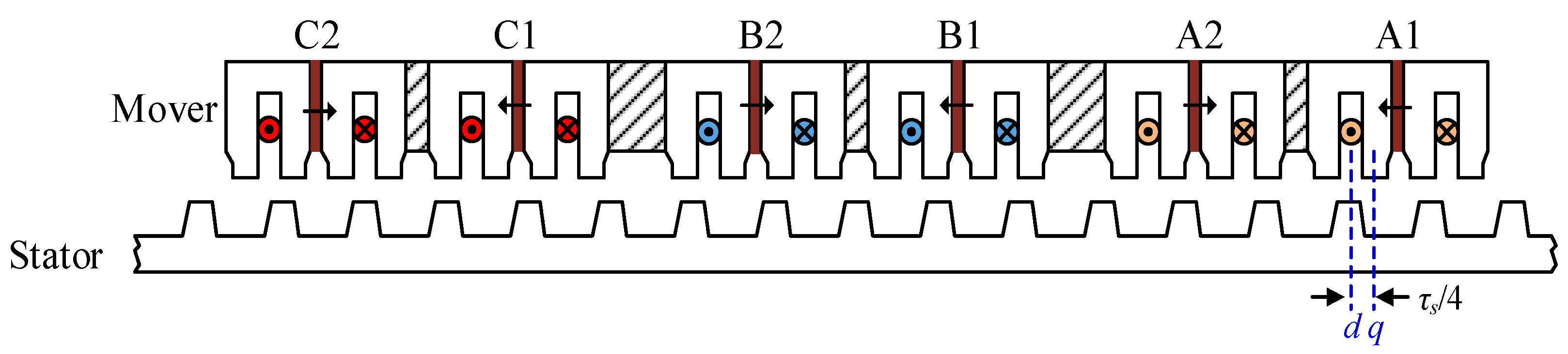
The studied PPMLM is composed of a primary mover and secondary stator as illustrated in Figure 1. Both the permanent-magnets and armature windings are equipped in movers. As is shown in Figure 1, the middle of stator teeth is defined as the d-axis with the maximum PM flux linkage. Meanwhile, the primary position is defined as the q-axis where PM flux linkage is minimum (zero). τs is the stator pole pitch, and the distance between two axes is τs/4. When the positive permanent-magnet flux linkage in phase-A winding is maximum, the corresponding primary position θe is defined as zero.
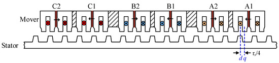
Figure 1.
Structure of the studied primary permanent-magnet linear motor (PPMLM).
According to the previous definition, the voltage equation of the studied PPMLM in dq coordinate system is expressed as:
with
where Rs and Ls are the mover resistance and inductance; ψPM is the permanent-magnet flux linkage; ud, uq and id, iq are the synchronous voltage and current components, respectively; ψd and ψq are the synchronous flux linkage components; and vm is the mover speed.
The thrust force Fe can be deduced as:
The motion equation is designed as:
where Fl is the load force; mt is the weight of PPMLM; B is the friction coefficient.
The studied PPMLM is fed by a two-level VSI, which is illustrated in Figure 2. The VSI consists of six power switches. The switch state sx of xth leg is defined as:
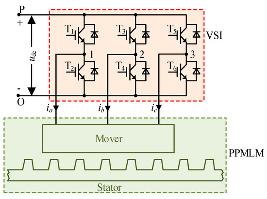
Figure 2.
Studied PPMLM traction system.
The VV of the VSI is defined as [sa sb sc]. All candidate VVs of VSI are presented in Table 1.

Table 1.
Voltage vectors (VVs) of voltage source inverter (VSI).
3. Two MPCCs for PPMLM
To clarify the description, the conventional and proposed MPCCs were defined as MPCC-I and MPCC-II in this paper, respectively. To simplify the analysis, two assumptions were given as follows: (1) the variation of mover speed vm could be neglected in one sampling period Ts; (2) the phase inductance Ls, the phase resistance Rs, and the peak value of PM flux linkage ψPM are considered unchanged during the entire operation.
3.1. MPCC-I
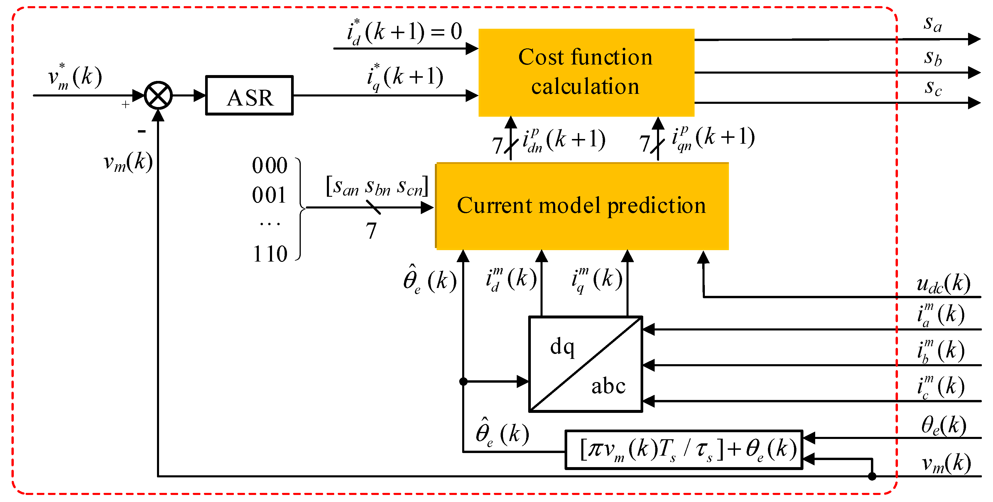
MPCC-I for the PPMLM traction system is shown in Figure 3, which contains two main modules: current model prediction and cost function calculation. In this paper, the average primary position was used in the model prediction, which is determined by . The primary position θe can be detected by the linear encoder.
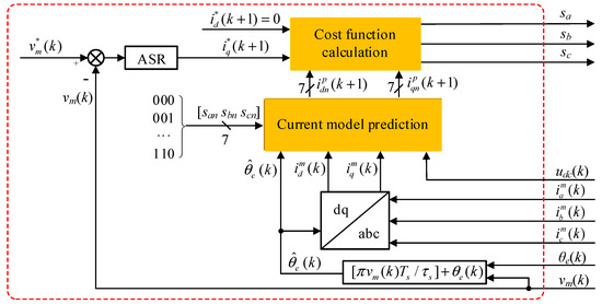
Figure 3.
Model predictive current control (MPCC)-I for the PPMLM traction system.
(1) Current model prediction:
In MPCC-I, synchronous currents of PPMLM are selected as control variables to calculate their predictive values. Substituting (2) into (1) gives:
According to the discrete time state-space model and Euler’s prediction formula, the current differential can be simplified as:
In this paper, the superscripts p and m indicate predictive and measured quantities; the symbol k indicates the kth sampling period.
Substituting (7) into (6) gives the predictive currents:
with
where and are the predictive synchronous currents by using the VV Un, respectively. T3s/2r is the transformation matrix from abc coordinate system to d-q coordinate system; udc is the dc bus voltage; udn and uqn are the synchronous components of the VV Un, respectively. The measured synchronous currents and can be calculated from the measured phase currents (,,) and the primary position θe(k).
(2) Cost function calculation:
According to (8), the cost function of MPCC-I is designed as:
where is the reference q-axis current. According to the difference between the reference speed and the actual value , can be obtained from the automatic speed regulator (ASR). is the reference d-axis current, which is set as 0. The optimal VV Uop is selected to minimize Jn:
3.2. MPCC-II
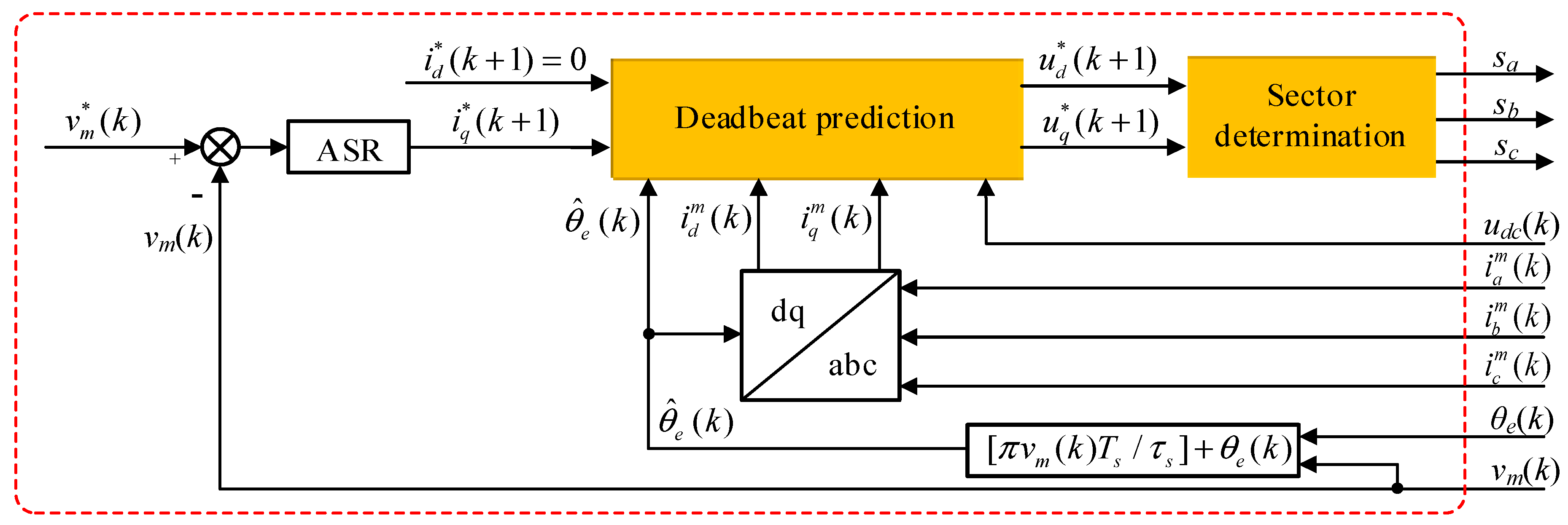
MPCC-II for the PPMLM traction system is shown in Figure 4, which contains two main modules: deadbeat prediction and sector determination.
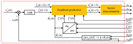
Figure 4.
MPCC-II for the PPMLM traction system.
(1) Deadbeat prediction:
It is assumed in this module that the reference currents and can be achieved in next sampling period. In other words, the predictive synchronous currents and should be equal to and , respectively. Substituting these equivalent relationships into (8) gives the reference synchronous voltages and :
with
However, the reference synchronous voltages and usually cannot be achieved since the candidate VVs of VSI are discrete as listed in Table 1.
(2) Sector determination:
To simplify the analysis, the distance of the VV Un is defined as Ln:
According to (13) and (15), the selection of the optimal VV Uop becomes to find the VV with the shortest distance, which was defined as the shortest distance principle in this paper. According to (10), seven Park transformations from abc coordinate system to dq coordinate system (udn, uqn) must be implemented to determine the optimal VV. To reduce the computation burden of coordinate transformation, dq components are expressed by αβ components:
Substituting (16) and (17) into (15) gives:
where uαn and uβn are the α- and β-axis components of the VV Un, respectively. The values of uαn and uβn are discrete, and they are listed in Table 2. According to (18), only one inverse Park transformation is implemented from dq coordinate system (, ) to αβ coordinate system (, ):
Table 2.
VVs in α-β coordinate system.
Comparing (18) with (15), the computation burden of (18) is significantly reduced. Comparing with the MPTC [28], the prediction amount has reduced from 4 to 1 by using MPCC-II, and the computation burden can be further reduced.
According to (18), a new cost function is developed as:
The optimal VV Uop is selected to minimize λn:
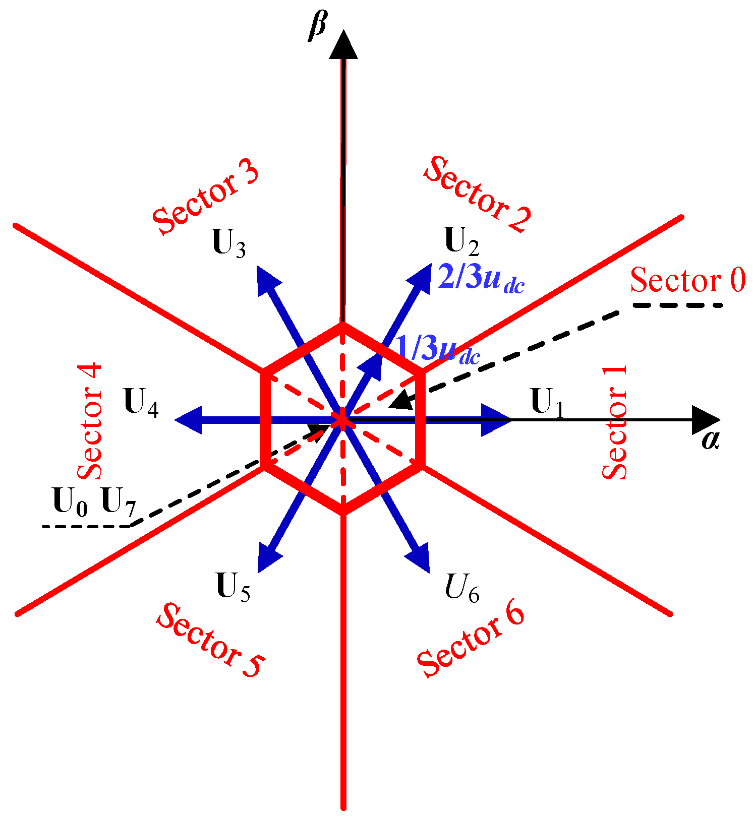
Based on the shortest distance principle, the distribution of the reference voltage vector U* was divided into seven sectors (Sector 0–6), as illustration in Figure 5. Un was chosen as the optimal VV when the reference voltage vector U* was located in Sector n. Especially, the central hexagon with radial length udc/3 is Sector 0, and one zero VV was chosen by minimum switching actions principle. To reduce the computation burden, a fast determination method of the optimal VV was designed for MPCC-II.

Figure 5.
Distribution of the reference voltage vector.
Firstly, the phase angle φ and the magnitude U* of the reference voltage vector are determined as:
Secondly, the direction code M of the reference voltage vector is determined according to the value of φ:
Thirdly, the relationship between the reference voltage vector and the central hexagon as shown in Figure 5 is determined by:
According to (24), the reference voltage vector locates in the central hexagon if H = 0; otherwise, the reference voltage vector locates outside of the central hexagon.
Finally, the optimal VV Uop is determined as:
4. Equivalence Analysis
The difference between two MPCCs is how to determine the optimal VV. For MPCC-I, the optimal VV is determined by the cost function (11), which can minimize the value of (11). As is listed in Table 1, there are eight VVs. If two zero VVs are considered as same, the number of candidate VVs can be reduced to 7. Therefore, seven different current groups [, ] can be predicted, and the cost function (11) will be calculated seven times. In some degree, MPCC-I is similarly like classical PWM. On the other hand, the reference synchronous voltages and are calculated by (13), and then the optimal VV can be determined by the location of the reference synchronous voltages in Figure 5. In fact, MPCC-II has referred to the SVM theory. However, both MPCCs can select the same optimal VV, and the equivalence of two MPCCs was analyzed in this section.
(8) is rewritten as:
Comparing (13) with (26), the voltage error can be calculated by:
Consequently, the initial form (11) can be simplified as:
According to (15) and (18), (28) can be rewritten as:
According to (20) and (29), two cost function formulas can be expressed as:
According to (30), MPCC-I and MPCC-II will select the same optimal VV. Hence, both MPCCs are equivalent.
5. Experimental Validation
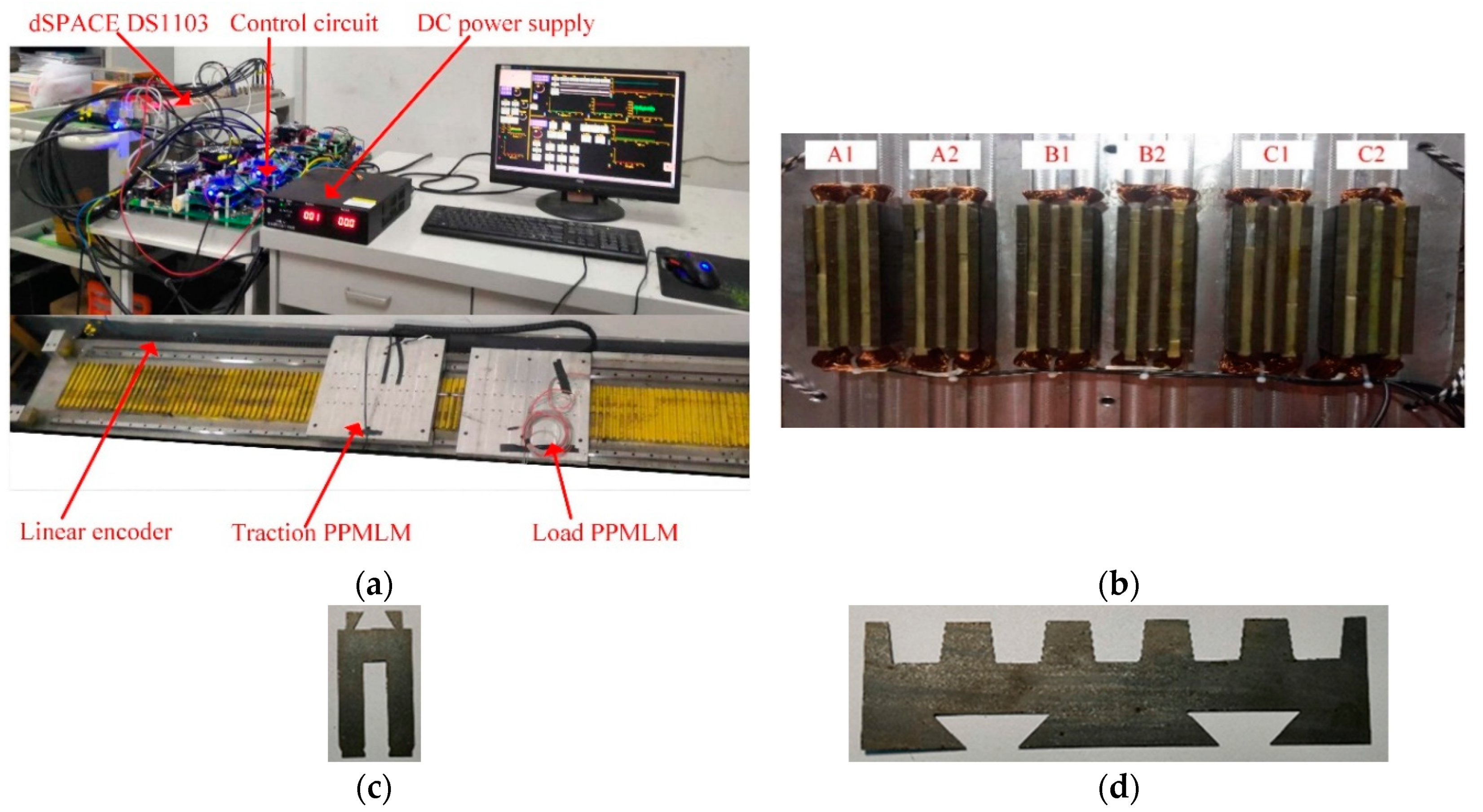
To verify the effectiveness of the proposed MPCC, the hardware should be able to measure the dc bus voltage, two phase currents and the primary position. There was no special requirement for the software. According to the hardware/software requirements, a test bench was designed as illustrated in Figure 6, and the parameters of the studied PPMLM are listed in Table 3. A dSPACE DS1103 controller was adopted to execute the control algorithm. DC bus voltage was measured by a voltage sensor (LEM LV25-P, LEM, Geneva, Switzerland). Phase currents are sensed by two current sensors (LEM LA55-P/SP50, LEM, Geneva, Switzerland). The primary position was detected by the linear encoder. The VSI was manufactured by Infineon, and its switch states were determined by the dSPACE DS1103 controller. The sampling frequency was 20 kHz. To compare the two MPCCs, several experiments were carried out.
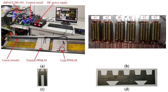
Figure 6.
Test bench: (a) Entire view, (b) bottom view of mover, (c) stator teeth, and (d) stator teeth.
Table 3.
Parameters of PPMLM.
5.1. Steady-State Experiment
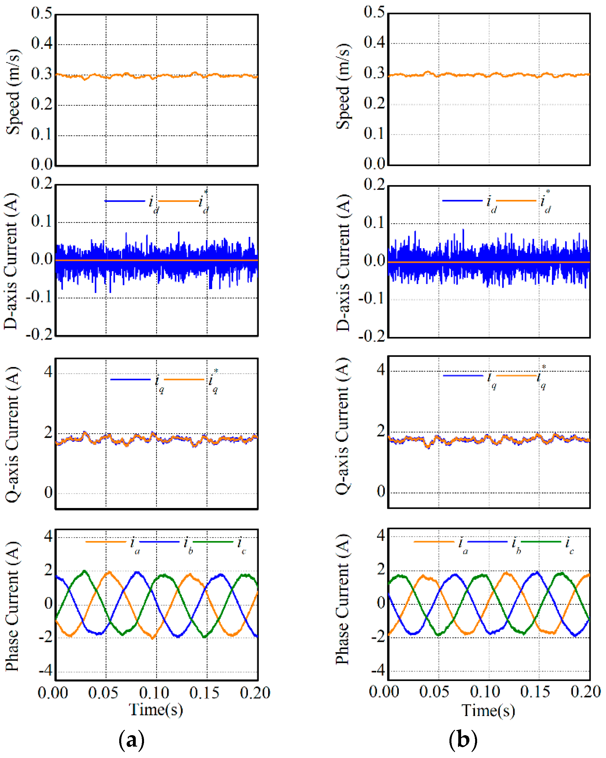
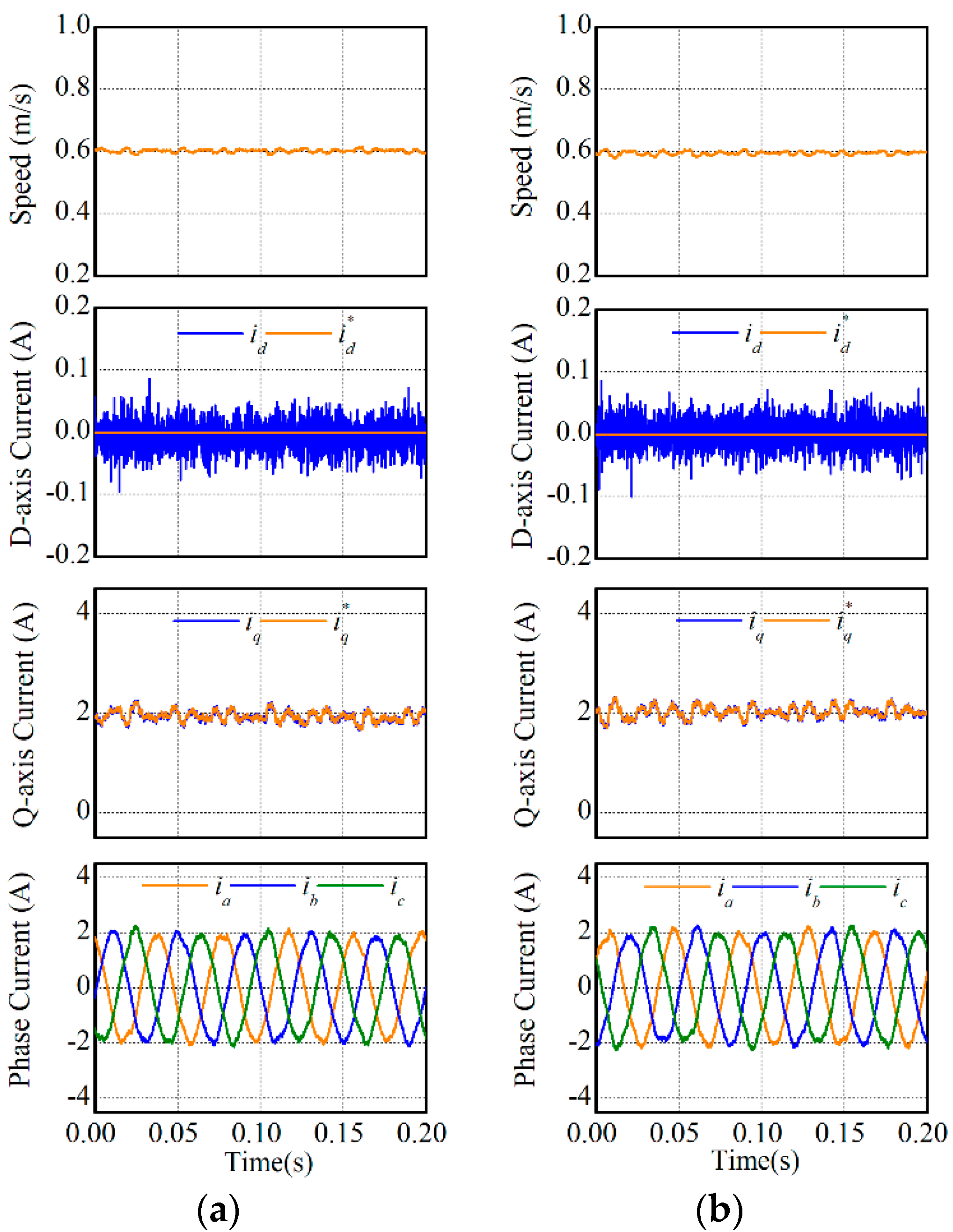
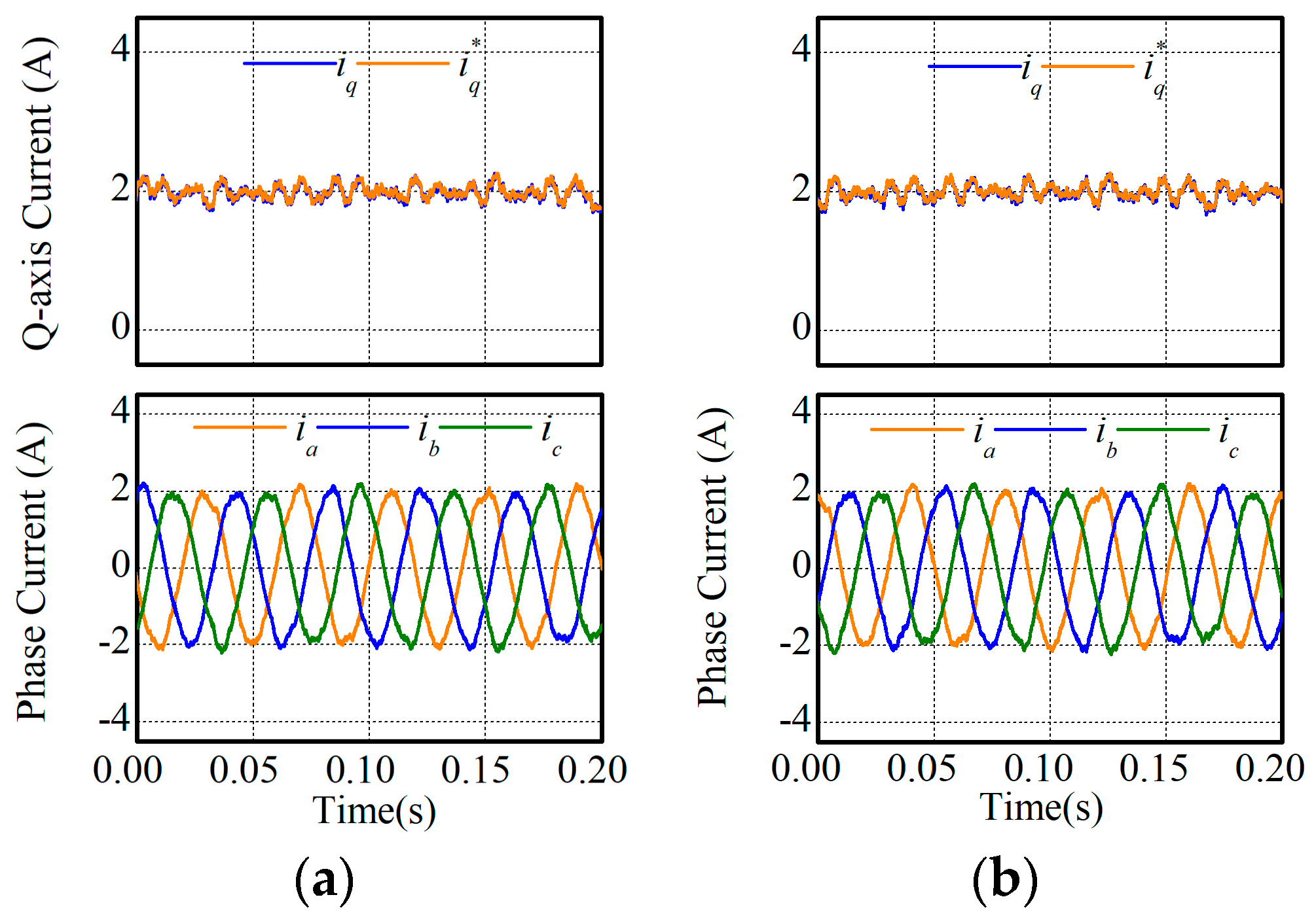
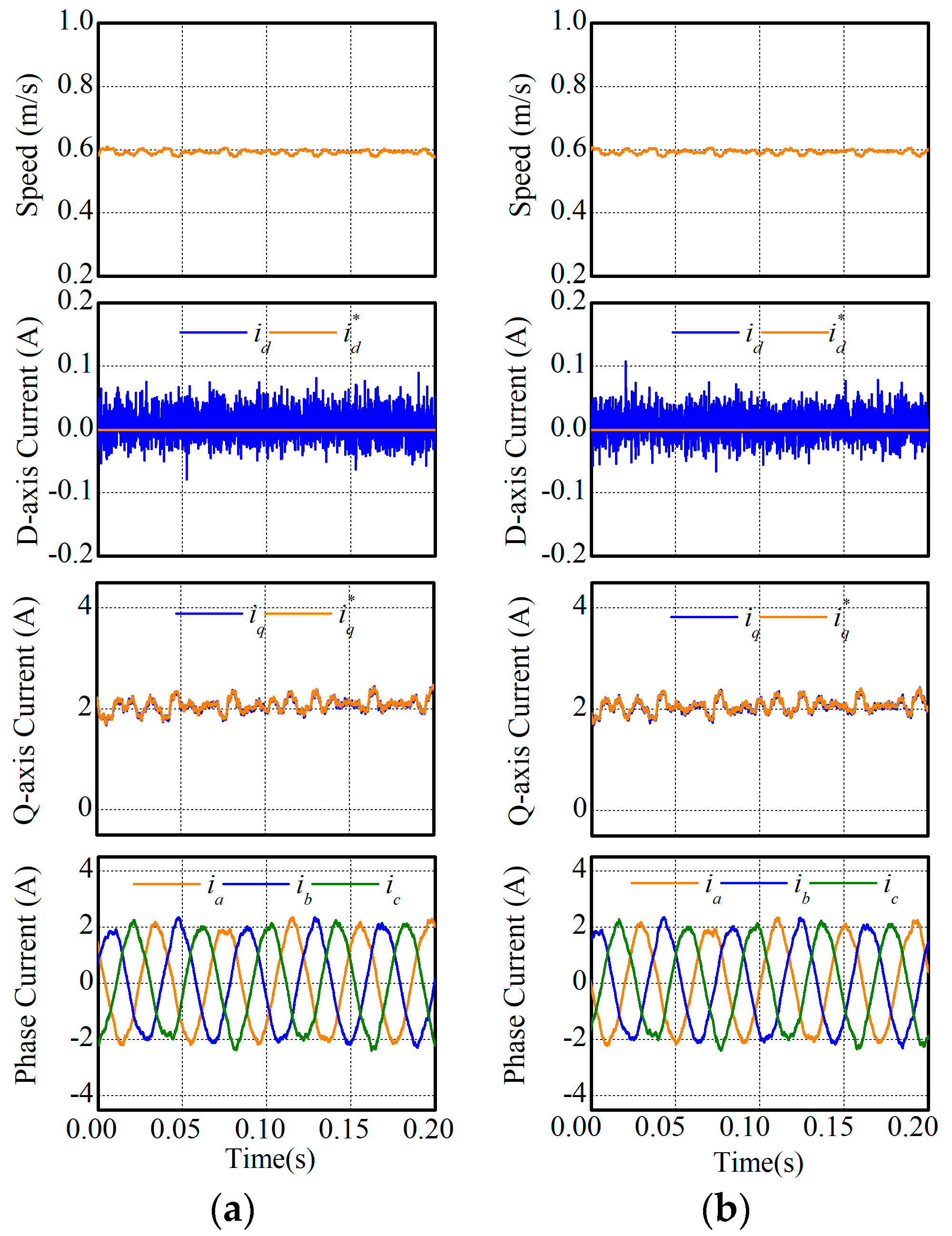
In this experiment, the steady-state performances of two MPCCs were compared. The reference speed was respectively set as 0.3 m/s and 0.6 m/s, and experimental results are respectively illustrated in Figure 7 and Figure 8. According to the experimental results, speed, synchronous currents, and phase currents were compared in Table 4. It can be found in Table 4 that MPCC-I and MPCC-II had nearly the same performance regarding speed, synchronous currents, and phase currents.
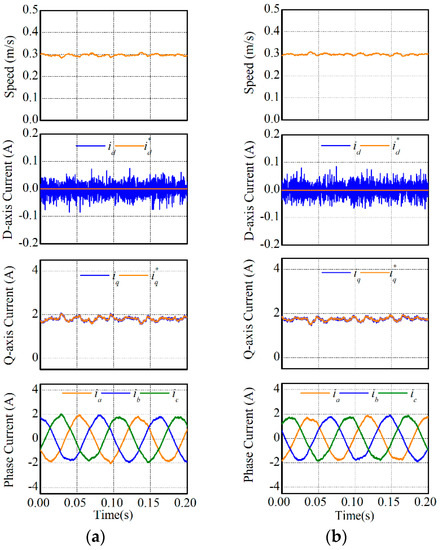
Figure 7.
Steady-state performances under 0.3 m/s: (a) MPCC-I and (b) MPCC-II.
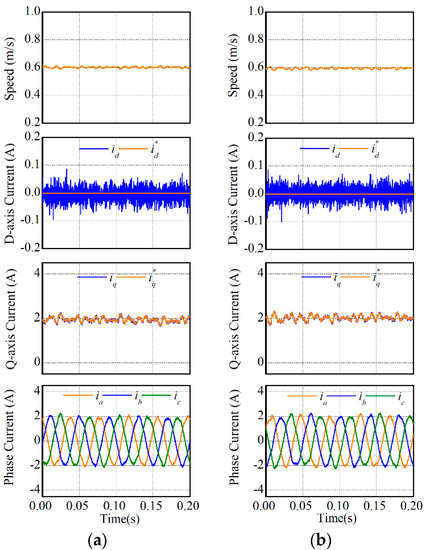
Figure 8.
Steady-state performances under 0.6 m/s: (a) MPCC-I and (b) MPCC-II.
Table 4.
Comparison of steady-state performances.
In the steady-state operation, the implement times of MPCC-I and MPCC-II in one sampling period were 12 μs and 9 μs, respectively. Hence, the computation burden could be reduced by 25% if MPCC-II was employed.
5.2. Speed Response Experiment
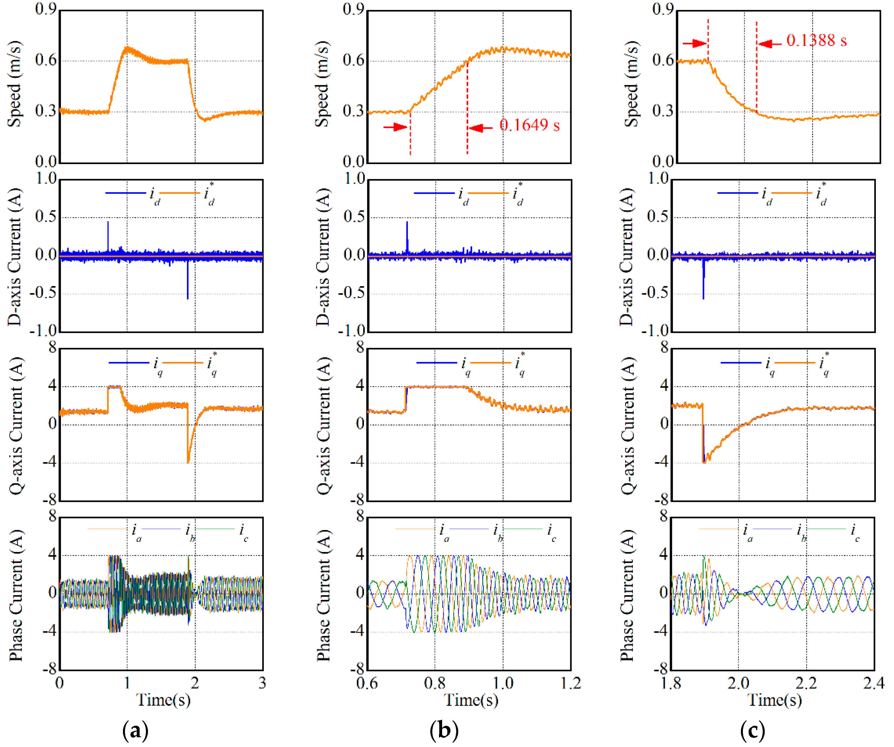
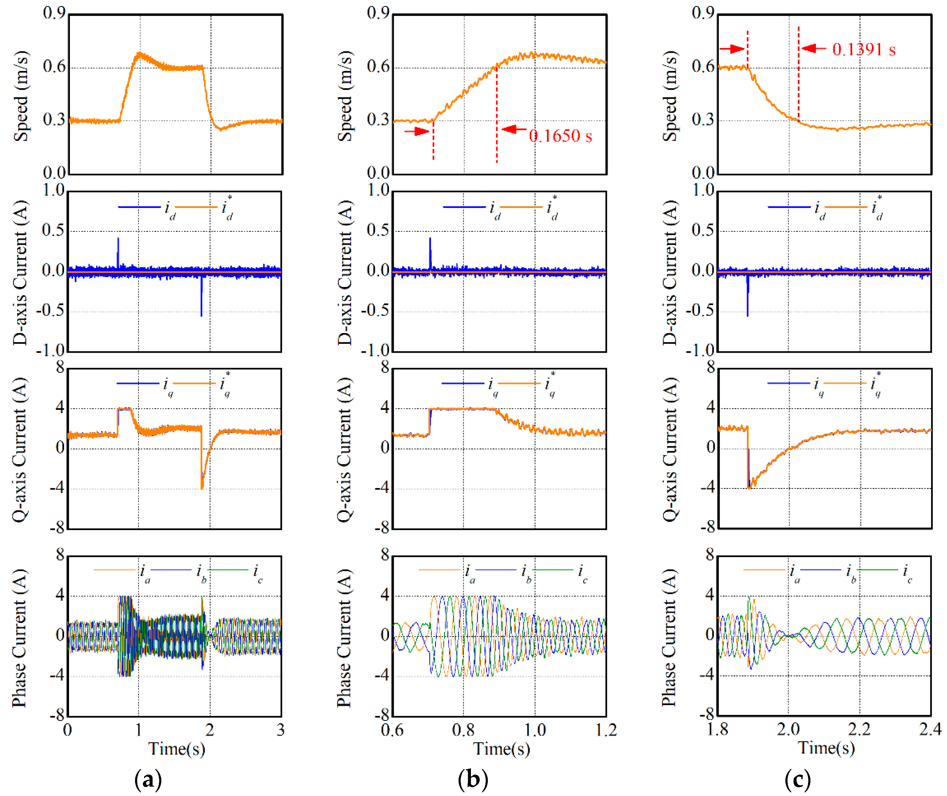
In this experiment, the speed response performances of two MPCCs were compared. The reference speed was changed between 0.3 m/s and 0.6 m/s. The experimental results are shown in Figure 9 and Figure 10. The integral time absolute error (ITAE) was introduced in this paper to evaluate the transient performances. The rising time of MPCC-I and MPCC-II were respectively 0.1649 s (ITAE value: 0.00743 m∙s) and 0.1650 s (ITAE value: 0.00746 m·s), while the falling time were respectively 0.1388 s (ITAE value: 0.00402 m·s) and 0.1391 s (ITAE value: 0.00400 m·s). The dynamic performances of synchronous currents and phase currents were also the same in two MPCCs. Hence, both MPCCs nearly demonstrated the same speed response performance.
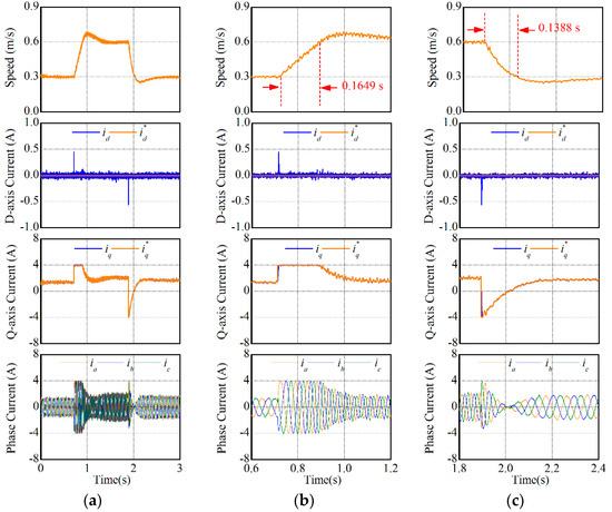
Figure 9.
Speed response performances of MPCC-I. (a) t = 0–3 s, (b) t = 0.6–1.2 s, and (c) t = 1.8–2.4 s.
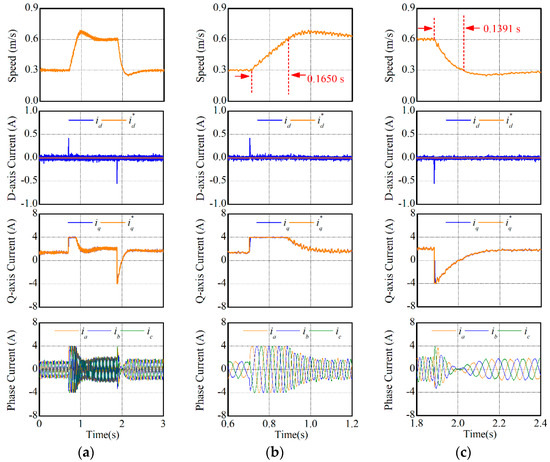
Figure 10.
Speed response performances of MPCC-II. (a) t = 0–3 s, (b) t = 0.6–1.2 s, and (c) t = 1.8–2.4 s.
5.3. Thrust Force Response Experiment
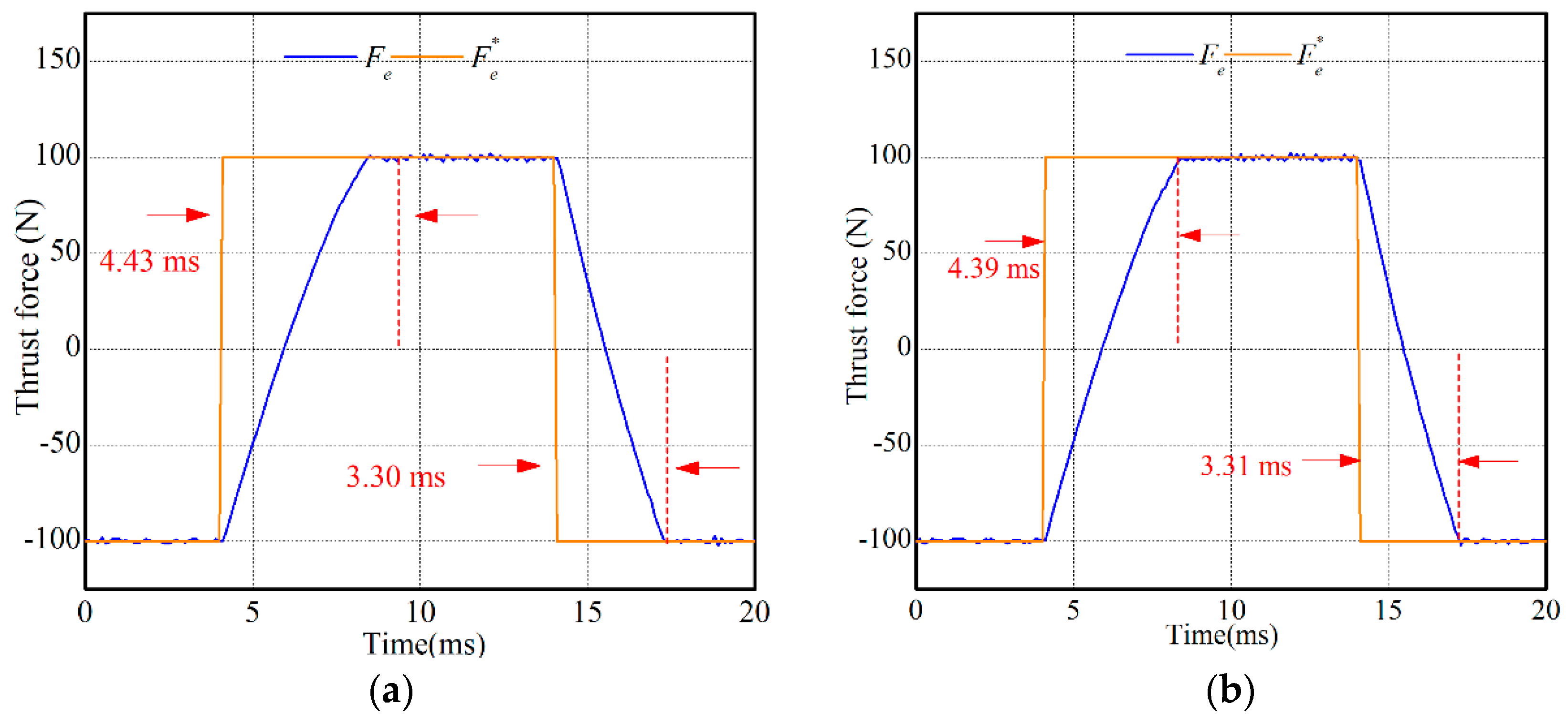
In this experiment, the thrust force response performances of both MPCCs were compared. The reference thrust force was increased from −100 N to 100 N, and then returned to −100 N. Figure 11 shows the experimental results. It can be found in Figure 11 that both MPCC-I and MPCC-II had fast thrust force response. The rising and falling time of MPCC-I were respectively 4.43 m·s (ITAE value: 0.00538 N·s2) and 3.30 m·s (ITAE value: 0.00339 N·s2) while those of MPCC-II were respectively 4.39 m·s (ITAE value: 0.00542 N·s2) and 3.31 m·s (ITAE value: 0.00341 N·s2). Hence, MPCC-I and MPCC-II had nearly the same thrust force response.
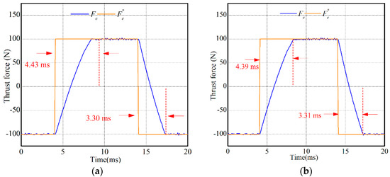
Figure 11.
Thrust force response performances: (a) MPCC-I and (b) MPCC-II.
5.4. Comparison of VV Selection
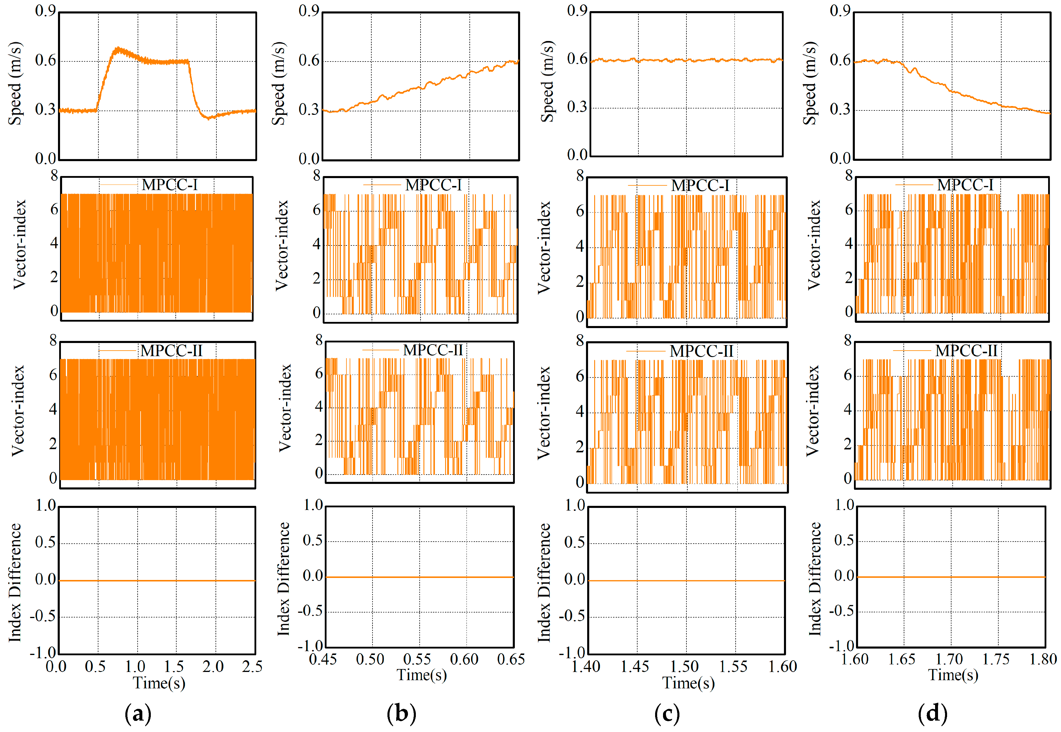
Both MPCCs run at the same time in this experiment but only the command signals of MPCC-II were implemented by the VSI. In other words, the command signals of MPCC-I were generated only for comparison instead of implementation. The reference speed was changed between 0.3 m/s and 0.6 m/s. Experimental results are illustrated in Figure 12, in which the numbers 0–7 respectively represent U0–U7. It can be found in Figure 12 that both MPCCs always selected the same VV no matter in transient- or steady-state operations. Therefore, the equivalence of both MPCC was well verified.

Figure 12.
Comparison of VV selection by both MPCCs. (a) t = 0–2.5 s, (b) t = 0.5–0.70 s, (c) t = 1.4–1.6 s, and (d) t = 1.7–1.9 s.
5.5. Motor Parameter Variation
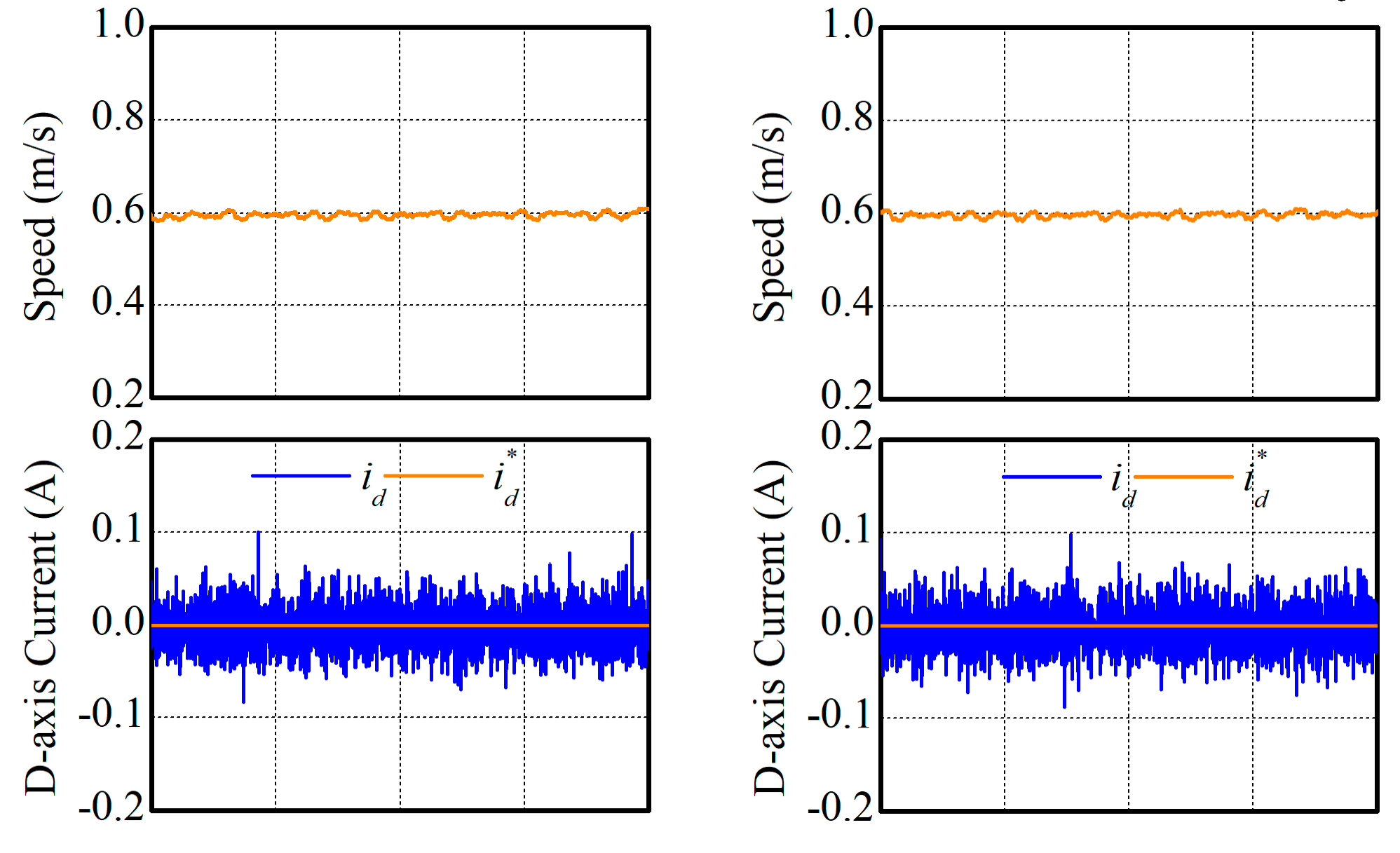
It is well known that MPCC is sensitive to the accuracy of the motor modeling, unmatched parameters, uncertainties, and disturbances. Therefore, compensation actions are usually necessary if high-performances are required. However, the purpose of this paper was to provide a simple but equivalent MPCC. Hence, there were no compensation actions taken in this paper. Some details about parameter compensation of MPCC can be found in [23]. In this subsection, the simplification and equivalence of MPCC-II were evaluated considering the motor parameter variation. As an example, 150% of the rated mover inductance and 50% of the rated mover resistance were considered in this experiment, and the experimental results are illustrated in Figure 13 and Figure 14. According to the experimental results, the performances of both MPCCs are compared in Table 5 and Table 6. It can be found in the two previous tables that MPCC-I and MPCC-II still had nearly the same performances.

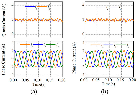
Figure 13.
Steady-state performances with inaccurate mover inductance: (a) MPCC-I and (b) MPCC-II.
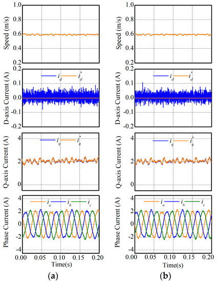
Figure 14.
Steady-state performances with inaccurate mover resistance: (a) MPCC-I and (b) MPCC-II.
Table 5.
Performance comparison with inaccurate mover inductance.
Table 6.
Performance comparison with inaccurate mover resistance.
6. Conclusions
For the reduction of the computation burden, a simple but equivalent solution was proposed for the MPCC of PPMLM traction systems. In the proposed MPCC, a continuous reference VV was predicted, and the optimal VV was determined according to the shortest distance principle instead of the cost function. Though the performances of the proposed MPCC were not enhanced in terms of precision, robustness, and dynamics, the computation cost could be significantly reduced, which achieved the target of this paper. The simplification and the equivalence of the proposed MPCC were verified by experimental results. Although the proposed MPCC was designed for PPMLM originally, it is also novel for the rotary PMSM. From the viewpoint of the implementation, there is no difference between the PMLM and the rotary PMSM.
Author Contributions
Conceptualization, W.W.; Methodology, W.W. and Z.L.; Validation, Z.L.; Resources, W.H., Z.W. and M.C.; Writing—original draft preparation, W.W. and Z.L.; Writing—review and editing, W.W.
Funding
This work was supported in part by National Natural Science Foundation of China (Project: 51977036 and 51607038), Jiangsu Natural Science Foundation of China (Project: BK20160673), the Fundamental Research Funds for the Central Universities of China (Project: 2242017K41005) and ZhiShan Young Scholar Plan of Southeast University of China (Project: 2242019R40043).
Conflicts of Interest
The authors declare no conflict of interest.
References
- Sun, G.; Ma, Z.; Yu, J. Discrete-time fractional order terminal sliding mode tracking control for linear motor. IEEE Trans. Ind. Electron. 2018, 65, 3386–3394. [Google Scholar] [CrossRef]
- Xu, W.; Dian, R.; Liu, Y.; Hu, D.; Zhu, J. Robust flux estimation method for linear induction motors based on improved extended state observers. IEEE Trans. Power Electron. 2019, 34, 4628–4640. [Google Scholar] [CrossRef]
- Huang, X.; Li, J.; Zhang, C.; Qian, Z.; Li, L.; Gerada, D. Electromagnetic and thrust characteristics of double-sided permanent magnet linear synchronous motor adopting staggering primaries structure. IEEE Trans. Ind. Electron. 2019, 66, 4826–4836. [Google Scholar] [CrossRef]
- Li, J.; Li, W.; Deng, G.; Ming, Z. Continuous-behavior and discrete-time combined control for linear induction motor-based urban rail transit. IEEE Trans. Magn. 2016, 52, 1–4. [Google Scholar] [CrossRef]
- Dong, D.; Huang, W.; Wang, Q. Modeling and optimization of a tubular permanent magnet linear motor using transverse-flux flux-reversal topology. IEEE Trans. Ind. Appl. 2019, 55, 1382–1391. [Google Scholar] [CrossRef]
- Hellinger, R.; Mnich, P. Linear motor-powered transportation: History, present status, and future outlook. Proc. IEEE. 2009, 97, 1892–1900. [Google Scholar] [CrossRef]
- Lv, G.; Zhou, T.; Zeng, D.; Liu, Z. Design of ladder-slit secondaries and performance improvement of linear induction motors for urban rail transit. IEEE Trans. Ind. Electron. 2018, 65, 1187–1195. [Google Scholar] [CrossRef]
- Du, H.; Chen, X.; Wen, G.; Yu, X.; Lü, J. Discrete-time fast terminal sliding mode control for permanent magnet linear motor. IEEE Trans. Ind. Electron. 2018, 65, 9916–9927. [Google Scholar] [CrossRef]
- Hang, J.; Xia, M.; Ding, S.; Li, Y.; Sun, L.; Wang, Q. Research on vector control strategy of surface-mounted permanent magnet synchronous machine drive system with high-resistance connection. IEEE Trans. Power Electron. 2019. [Google Scholar] [CrossRef]
- He, Z.; Dong, F.; Zhao, J.; Wang, L.; Song, J.; Wang, Q.; Song, X. Thrust ripple reduction in permanent magnet synchronous linear motor based on tuned viscoelastic damper. IEEE Trans. Ind. Electron. 2019, 66, 977–987. [Google Scholar] [CrossRef]
- Chung, S.; Kim, J.; Woo, B.; Hong, D.; Lee, J.; Koo, D. Force ripple and magnetic unbalance reduction design for doubly salient permanent magnet linear synchronous motor. IEEE Trans. Magn. 2011, 47, 4207–4210. [Google Scholar] [CrossRef]
- Cao, R.; Jin, Y.; Lu, M.; Zhang, Z. Quantitative comparison of linear flux-switching permanent magnet motor with linear induction motor for electromagnetic launch system. IEEE Trans. Ind. Electron. 2018, 65, 7569–7578. [Google Scholar] [CrossRef]
- Zhang, Z.; Tang, X.; Zhang, C.; Li, M. Novel decoupling modular permanent magnet flux-switching linear motor. IEEE Trans. Ind. Electron. 2019, 66, 7603–7612. [Google Scholar] [CrossRef]
- Wang, W.; Feng, Y.; Shi, Y.; Cheng, M. Fault-tolerant control of primary permanent-magnet linear motors with single phase current sensor for subway applications. IEEE Trans. Power Electron. 2019, 34, 10546–10556. [Google Scholar] [CrossRef]
- Zhao, W.; Yang, A.; Ji, J.; Chen, Q.; Zhu, J. Modified flux linkage observer for sensorless direct thrust force control of linear vernier permanent magnet motor. IEEE Trans. Power Electron. 2019, 34, 7800–7811. [Google Scholar] [CrossRef]
- Cheema, M.A.M.; Fletcher, J.E.; Xiao, D.; Rahman, M.F. A direct thrust control scheme for linear permanent magnet synchronous motor based on online duty ratio control. IEEE Trans. Power Electron. 2016, 31, 4416–4428. [Google Scholar] [CrossRef]
- Zhao, W.; Wu, B.; Chen, Q.; Zhu, J. Fault-Tolerant Direct Thrust Force Control for a Dual Inverter Fed Open-End Winding Linear Vernier Permanent-Magnet Motor Using Improved SVPWM. IEEE Trans. Ind. Electron. 2018, 65, 7458–7467. [Google Scholar] [CrossRef]
- Wang, W.; Feng, Y.; Shi, Y.; Cheng, M.; Wang, Z. Direct thrust force control of primary permanent-magnet linear motors with single DC-link current sensor for subway applications. IEEE Trans. Power Electron. 2019. [Google Scholar] [CrossRef]
- Geyer, T.; Papafotiou, G.; Morari, M. Model predictive direct torque control—Part I: Concept, algorithm, and analysis. IEEE Trans. Ind. Electron. 2009, 56, 1894–1905. [Google Scholar] [CrossRef]
- De Castro, A.; Pereira, W.; De Almeida, T.; De Oliveira, C.; Monteiro, J.; Oliveira, A. Improved finite control-set model-based direct power control of BLDC motor with reduced torque ripple. IEEE Trans. Ind. Appl. 2018, 54, 4476–4484. [Google Scholar] [CrossRef]
- Wang, W.; Zhang, J.; Cheng, M. Common model predictive control for permanent-magnet synchronous machine drives considering single-phase open-circuit fault. IEEE Trans. Power Electron. 2017, 32, 5862–5872. [Google Scholar] [CrossRef]
- Karamanakos, P.; Geyer, T. Model predictive torque and flux control minimizing current distortions. IEEE Trans. Ind. Appl. 2019, 34, 2007–2012. [Google Scholar] [CrossRef]
- Zhang, X.; Zhang, L.; Zhang, Y. Model predictive current control for PMSM drives with parameter robustness improvement. IEEE Trans. Power Electron. 2019, 34, 1645–1657. [Google Scholar] [CrossRef]
- Nguyen, H.; Jung, J. Asymptotic stability constraints for direct horizon-one model predictive control of SPMSM drives. IEEE Trans. Power Electron. 2018, 33, 8213–8219. [Google Scholar] [CrossRef]
- Lim, C.; Rahim, N.; Hew, W.; Levi, E. Model predictive control of a two-motor drive with five-leg-inverter supply. IEEE Trans. Power Electron. 2013, 60, 54–65. [Google Scholar] [CrossRef]
- Duran, M.; Prieto, J.; Barrero, F.; Toral, S. Predictive current control of dual three-phase drives using restrained search techniques. IEEE Trans. Ind. Electron. 2011, 58, 3253–3263. [Google Scholar] [CrossRef]
- Barrero, F.; Arahal, M.; Gregor, R.; Toral, S.; Duran, M. One-step modulation predictive current control method for the asymmetrical dual three-phase induction machine. IEEE Trans. Ind. Electron. 2009, 56, 1974–1983. [Google Scholar] [CrossRef]
- Xie, W.; Wang, X.; Wang, F.; Xu, W.; Kennel, R.; Gerling, D.; Lorenz, R. Finite-control-set model predictive torque control with a deadbeat solution for PMSM drives. IEEE Trans. Ind. Electron. 2015, 62, 5402–5410. [Google Scholar] [CrossRef]

© 2019 by the authors. Licensee MDPI, Basel, Switzerland. This article is an open access article distributed under the terms and conditions of the Creative Commons Attribution (CC BY) license (http://creativecommons.org/licenses/by/4.0/).