Abstract
As environmental requirements become more stringent, the liquid carbon dioxide blasting system is one of the non-explosive blasting technologies that, with low tensile stress energy, will replace the chemical explosive blasting technology, and the impact pressure characteristic of high-pressure fluid is a crucial factor in the process of rock breaking. To further investigate the impact and pressure attenuation characteristics of high-pressure fluid during the phase transition of liquid carbon dioxide blasting system, the pressure curves of high-pressure fluid in liquid carbon dioxide blasting systems at different distances were measured in the laboratory. Based on the mechanism analysis of phase transition kinetics, the initial jet velocity of the four experiments was calculated, and the rationality of results was verified by the Bernoulli equation. The general expression of the positive phase pressure–time function was proposed, and the idealized impact pressure curve can be divided into five stages. The impact pressure field of the liquid carbon dioxide blasting system can be divided into three areas at different distances: the explosive jet impact zone, the jet edge zone and the shock wave action zone, and the pressure–contrast distance fitting equation of the liquid carbon dioxide blasting system were obtained.
1. Introduction
In the process of rock excavation, although explosive blasting plays a dominant role, the requirements for effective rock breaking energy per unit and environmental safety are becoming more and more strict. The non-explosive blasting technology with low tensile stress energy will replace the chemical explosive blasting technology. The liquid carbon dioxide blasting system is one of the non-explosive blasting technologies. Liquid carbon dioxide is transformed into a gaseous state through a reusable special blasting tube, generating powerful expansion energy instantly. High-pressure fluid or gas releases quickly and generates a tensile stress field in the rock mass, so as to achieve the effect of pre-splitting or crushing rock mass.
Liquid carbon dioxide blasting technology can be traced back to the USA in the 1930s [1,2], and then it became extensively used during the early 1950s [3,4,5], when a liquid carbon dioxide phase transition device was invented by a British company called Cardox. Due to the rapid development of coal mining technologies and fully mechanized mining machines, the Cardox system is rarely used today in coal mining [6]. Over the past twenty years, with the coal mining safety concern and chemical explosives control, the advantages of the Cardox system is exposed again in some coal mines [7,8,9,10], urban construction projects [11], frozen soil blasting [12], rock breaking, and concrete demolition blasting under a special circumstances [13,14,15].
The Cardox system consists of a high-strength, reusable steel tube filled with liquid carbon dioxide, a chemical energizer/Cardox safety heater, and a rupture disc. When the Cardox tube is ignited, the carbon dioxide is almost instantaneously converted from liquid to supercritical carbon dioxide [6], which is released from the tube and expands through micro-cracks and fractures in the rock. Pressure released from the gaseous carbon dioxide can be regulated between 1200 and 2800 bar by using different rupture disks with varying thickness. The period of time for the pressure rise stage is about 0.026 to 0.086 s, and that, for the pressure release stage, is about 0.00018 to 0.00026 s [6]. Figure 1 shows a schematic diagram of the components that makes up the cartridge. The chemical energizer is activated by a small electrical charge which causes the blasting.
Figure 1.
Schematic diagram of a Cardox system [6].
Compared with other rock breaking methods, the damage at lower tensile stress levels is more efficient in the utilization of energy, less vibration, pollution free, reduce the damage of the surrounding rock mass, and destruction of the environment. Of course, this technology has some limitations, such as high labor intensity and lower work efficiency, which are not suitable for large-scale mining and engineering construction. In addition, due to the easy gasification of carbon dioxide, it is less efficient to charge liquid carbon dioxide in high-temperature areas.
Nowadays, the research of liquid carbon dioxide blasting mainly focuses on coal seam anti-reflection, thermodynamic properties, energy calculation, pressure characteristic, mechanism of fracture, and its application. Lu et al. [2], Chen et al. [16], He et al. [17], Kang et al. [18], Wang et al. [19], Zhao [20], Huo [21], and Dong et al. [22] studied the permeability improvement of liquid carbon dioxide phase transition on the basis of foreign liquid carbon dioxide blasting systems, gave two energy calculation equations, and analyzed the trinitrotoluene (TNT) equivalent of liquid carbon dioxide phase change process and the mechanism of fracture. Based on the Span and Wagner carbon dioxide equation of state [23] and the thermodynamics of explosions, the influence of thermodynamic properties of liquid carbon dioxide and the explosion of energy during the phase transition was further investigated through experimental methods, the conclusion that the carbon dioxide in the blasting tube is supercritical before the rupture disc broken was obtained, and a more accurate method was proposed to calculate the energy of explosion of liquid carbon dioxide blasting systems [6]. Tests had been carried out using specially developed techniques to determine the gas pressures associated with the blast wave and the velocity with which the wave travels through the sandy shale [24]. In order to investigate the explosion pressure variation and rock breaking characteristics of liquid carbon dioxide blasting technology, the liquid carbon dioxide blasting experiment under free field condition and the liquid carbon dioxide rock breaking experiment were carried out [25]. The peridynamics model of rock fracturing under liquid carbon dioxide blasting was established, and the crack propagation in liquid carbon dioxide blasting and the influence of explosion pressure and numbers and radii of releasing holes on the liquid carbon dioxide blasting effects were analyzed [26]. A test study on the permeability enhancement of cross-measure boreholes using liquid carbon dioxide phase-transition blasting to identify an effective method for enhancing coalbed methane reservoir [27]. A newly designed experimental apparatus is developed to monitor shock-wave pressure of liquid CO2 blasting [28]. A mathematical model for blasting was established based on such three major parameter variables as initial peak impact pressure, effective radius of cracked circle, and diameter of blasting-split borehole under non-coupling split conditions for the study on the evolutionary characteristics of damage and destruction to gas-rich coal seam resulting from carbon dioxide phase-transition blasting [29]. Zhu et al. [30] established the damage mechanics model of rock fractured by high-pressure gas, and studied the mechanics of the crack generation and development at two-stages of stress wave and quasi-static. Then, the change law of gas drainage concentration under different surrounding rock stress condition is analyzed by means of numerical experiments. Sun et al. [31] simulated the generation of initial crack in supercritical carbon dioxide blasting coal with experimental methods. Gao et al. [32] combine theoretical and practical methods to analyze the mechanism by which high-pressure gas breaks rock at different stages.
Rock fracture is a complex dynamic process under the action of high-pressure carbon dioxide fluid, including the impact characteristics of high-pressure jet and positive phase pressure–time function, the formation and propagation of cracks, the scope of the disturbance, the equivalent of the blasting, and the stress–strain around the drilling hole. Moreover, the impact pressure of high-pressure fluid determines the crack geometrical form and propagation mode of the rock mass. However, the pressure of high-pressure fluid damage to the rock with three parameters: peak pressure, effect time of positive phase area, and impulse density. Therefore, the attenuation law of positive phase and the mathematical model are the keys to studying the impact characteristics of liquid carbon dioxide blasting. However, according to the above literature review, for the liquid carbon dioxide blasting system, the positive phase pressure function and pressure attenuation characteristic of a high-pressure jet are not clear.
In this work, we will measure the curves of high-pressure fluid in liquid carbon dioxide blasting system at different distances. The initial jet velocity of the high-pressure fluid was calculated, the general expression of the positive phase pressure–time function was obtained, and the impact pressure characteristics and attenuation characteristics at different distances were analyzed and discussed.
2. Experimental Methodology
In order to measure the pressure attenuation characteristics of high-pressure fluid during the phase transition of liquid carbon dioxide blasting system, pressure sensors were arranged on both sides of the air outlet of the blasting tube to measure the pressure characteristic curves of explosion fields at different distances, as shown in Figure 2. Sensor A was used to measure the pressure inside the blasting tube; sensor B on the left of the figure was used to compare the pressure at the air outlet of each test; and a sensor on the right was used to measure the pressure at different distances. The distance between sensors C to K and the blasting tube center was 0.23 m, 0.6 m, 0.9 m, 1.2 m, 1.5 m, 1.8 m, 2 m, 2.5 m and 3 m, respectively. The parameters of the all pressure sensors are shown in Table 1.
Figure 2.
The principle diagram of the test.

Table 1.
The parameters of pressure sensors.
The primary equipment of the test system includes the following:
(1) The carbon dioxide filling system (Figure 2a) which includes one storage tank of liquid carbon dioxide, one filling machine, the carbon dioxide blasting tube, and the fixing device used for the filling of carbon dioxide. The liquid carbon dioxide storage tank is used to store liquid carbon dioxide. The filling machine consists of main switch, console, functional area, operating platform, and other components. The main switch controls the opening and closing of the whole liquid carbon dioxide filling system. The console can adjust the filling pressure of liquid carbon dioxide. The functional area can realize the functions of adjusting the filling speed, weighing filling quality, and so on. The operating platform mainly controls the filling operation of carbon dioxide. The fixture is used to fix the blasting tube and control its switch.
(2) The dynamic pressure measurement system (Figure 2b) includes the computer, the fixture, the TST6200 transient signal tester manufactured by Chengdu Test Electronic Information Co. Ltd. (Chengdu, China), and piezoelectric pressure sensors with different measuring ranges, and it can collect the internal pressure signals of the blasting tube in the whole process of the liquid carbon dioxide blasting.
All of the explosion tests were carried out in the air-raid shelter with an average temperature of 18 °C and an average humidity of 89%. First, the blasting tube was charged. Before filling, the entire filling system and the blasting tube were cooled down through 2–3 filling and exhaust cycles. The filling pressure was 9 MPa, and the dimensions of the blasting tube employed were 700 mm × Φ45 mm. The basting tube was then placed on the fixture in the testing system. The sampling frequency of dynamic acquisition apparatus was 50 KHz.
3. Results and Discussion
3.1. Velocity Attenuation Characteristic
(1) Initial velocity
The conclusion that the carbon dioxide in the blasting tube is supercritical before the energy release plate broke was obtained [6]. Supercritical carbon dioxide is a material state with special fluid characteristics. Its gas phase and liquid phase tend to be similar in nature. It can also be said that supercritical carbon dioxide is a homogeneous phase fluid, which not only has the compressibility and outflow of gas, but also has the fluidity of liquid. In the initial stage of boiling liquid expanding vapor explosion (BLEVE), after the destruction of energy release tablets, supercritical carbon dioxide two-phase flow spews out rapidly from the air outlet, and the rapid release of fluid belonged to the sonic or supersonic flow. In the outlet area, carbon dioxide vaporized rapidly, and the time was very short, where ; it was the critical flow, and the mass flow rate of the fluid was [33]
where ; it was subcritical flow, and the mass flow rate of the fluid was [33]
where Pa was atmospheric pressure, Pa; Pg was the pressure inside the blasting tube, Pa; was the quality flow rate of the gas phase component, kg/s; was gas mass, kg; t was time, s; Y was the expansion factor of gas; Cd was the gas leakage coefficient, Cd = 1 when the crack was round, Cd = 0.95 when the crack was triangular or diamond, and Cd = 0.90 when the crack was rectangular. A was the crack area, m2; was the adiabatic index of gas; M was the molecular mass of the gas, kg/mol; ; R was the general gas constant, 8.314 J/ (mol ∙K); T was fluid temperature, K.
The initial average velocity of discharge was [34]:
where denoted the density of gas in the air outlet (kg/m3).
The density of the air outlet fluid was the density of carbon dioxide in the blasting tube. Through Equations (2) and (3), the initial release velocity of the jet in the four tests was 469.93 m/s, 338.87 m/s, 496.32 m/s, and 419.81 m/s.
In order to verify the correctness of the calculation process, we simplified the model and estimated the liquid carbon dioxide jet velocity based on the Bernoulli equation. Within a very short time after the rupture of the energy release sheet, high-pressure carbon dioxide after gasification flowed out of the release hole to form high-pressure gas jet at high speed. The schematic diagram of high-pressure carbon dioxide jet was shown in Figure 3.
Figure 3.
The schematic diagram of a high-pressure carbon dioxide jet.
In the process of high-pressure carbon dioxide movement, the energy loss caused by blasting tube, directional shear fragment resistance, turbulence, eddy flow, gravitational field and other conditions were not considered, and no energy loss occurred during high-speed carbon dioxide motion at the moment of fracture of the directional shear sheet until the release hole. In this case, the Bernoulli equation of the ideal fluid was used to estimate the jet velocity v1 of carbon dioxide fluid at the release hole, which was:
where was the pressure of carbon dioxide inside the blasting tube at the moment before the explosion, was the density of carbon dioxide inside the blasting tube at the moment before the explosion, was the velocity of carbon dioxide inside the blasting tube at the moment before the explosion, was the pressure of high-speed carbon dioxide fluid released from the air outlet, was the density of high-speed carbon dioxide fluid released from the release hole, and was the velocity of high-speed carbon dioxide fluid released from the air outlet.
At the breaking moment of the energy release plate, it was considered that the carbon dioxide of blasting was in a static state, and the pressure was the maximum pressure before the breaking of the energy release plate. When the high-speed carbon dioxide fluid started to release from the air outlet, the gas carbon dioxide just started to contact the external atmosphere, so the pressure was atmospheric pressure at this time, while the density of carbon dioxide was relatively stable at the moment of release. The density measured by four experiments of liquid carbon dioxide under laboratory conditions was 0.103 MPa. By substituting the above data into Equation (4), the instantaneous velocity of carbon dioxide released from the release hole was 410.78 m/s, 343.14 m/s, 428.76 m/s, and 390.27 m/s.
(2) Basic characteristics of the jet
When carbon dioxide jet exited from the orifice at u0, it formed turbulent jet flow with the surrounding air, resulting in discontinuity surface with discontinuous velocity. As shown in Figure 4, the jet flow was mainly composed of the initial segment, transition segment, and the main segment. The initial section included the shear layer or mixing layer extending from the orifice boundary to the inside and outside and the potential flow core whose central part was not affected and whose velocity u0 was maintained. The main section of the jet was the jet after the full development of turbulence. The transition section of the jet was a very short fluid between the initial section and the main section, which was generally not considered.
Figure 4.
The flow characteristics of free turbulence jet.
(3) Attenuation law of axial flow velocity
The momentum flux of each section of the jet was conserved and equal to the momentum of the exit section, i.e.,
In the equation, u0 and r0 are the flow velocity and radius of the exit section, respectively, as shown in Figure 5.
Figure 5.
Axisymmetric free jet.
Considering the similarity of the flow velocity distribution of each section of the main body, namely:
Taking be as the characteristic half thickness, where r = be, u = um/e, substituting the above equation
Assuming that the jet thickness extends linearly, namely:
Then,
In the equation, c = 0.114, D is the diameter of the circular orifice, and the above equation became
This equation shows that the circular turbulent jet axis flow velocity varies with x−1.
Let um = u0, and the initial length of the circular turbulent jet can be obtained [27]:
Here, D is the diameter of the blasting tube 22 mm; therefore, the initial length of the circular turbulent jet of the liquid carbon dioxide blasting system was 0.136 m, and the pressure was also approximately equal within this range. In engineering applications, if the difference between the radius of the blast hole and the radius of the blast tube was greater than this value, the damage capability would be greatly reduced.
3.2. Positive Phase Pressure Function
Figure 6 shows the pressure–time history curves of the same distance outside the blast tube in the four explosion tests. The curves of the four tests have the same variation.
Figure 6.
Pressure–time history curve at the same distance outside the blast tube in the four explosion tests.
It was assumed that, under ideal conditions, an ideal pressure sensor was assumed for a given fixed distance R, which did not hinder the flow of the jet after impacting the pressure front and was able to perfectly record all pressure changes, as shown in Figure 7. The ideal jet impact pressure–time history curve recorded by the instrument. At some time after the explosion of the liquid carbon dioxide blasting system, the instrument recorded the ambient pressure P0. At the arrival time t0, the pressure rises abruptly to a certain peak value Ps+. Then, during time t0+t1, the pressure first decayed to a certain level value Ps for a time t2, then decayed to P0 via time t3, then continued to fall to Ps−, and finally returns to P0 during the experiencing time t4. The pressure–time history curve of the pressure from the peak Ps+ to the ambient pressure P0 was called the positive phase. The pressure–time history curve of the pressure between the ambient pressures P0 and Ps− was a negative phase. The positive and negative phase impulses were defined by the following equation [35]:
Figure 7.
Impact pressure–time history curve of the liquid carbon dioxide blasting system.
The damage effect of the jet impact pressure on the target can be measured by three parameters: (1) peak pressure; (2) positive phase zone action time; and (3) impulse density I+. It can be seen from the above analysis that the decay law and mathematical model of the positive phase are the keys to study the impact pressure curve of the liquid carbon dioxide blasting jet.
For traditional ideal blast or shock waves, there was a large amount of research work based on experimental tests, according to theoretical analysis, the following pressure–time history function forms are recommended [35]:
(1) Linear attenuation function
This is the simplest form of function with two arguments. The shock wave pressure reaches a maximum at the beginning of the explosion, the form of the assumed linear decay of pressure when considering the blast wave load of the structure:
where t+ is positive phase time (). When fitting experimental data with this function, the actual value of is usually reserved, and the positive phase duration t+ is adjusted to maintain the actual positive impulse I+. It is also possible to adjust the positive phase duration so that the initial decay rate of Equation (14) matches the initial decay rate of the test data. This will cause the positive impulse to be small which often used for response calculations.
(2) Exponential decay function
where is attenuation index, and the function form is a commonly used function expression in the pressure decay law; many experimental data results indicate that the expression will accurately fit the records of many instruments on most positive phases. If someone gets relevant experimental results, he can obtain related pending parameters to perform regression analysis by using the functional expressions (14) and (15).
(3) Three parameter function
This function expression is often referred to as the “modified Friedlander’s equation [35]”, which can describe the details of pressure changes well in many cases.
(4) Four parameter function
Many scholars have noticed that the data of the exponential decay rate decrease with time in the experiment, who put forward a four-parameter function expression that allows for more degrees of freedom:
The characteristics of Ps+、t+、I+ and exponential decay rate can be fitted and analyzed by use according to the equation.
(5) Five parameter function
According to the computing theory that shock wave generated by blasting point, Broad has put forward a function expression consisting of a five-parameter model to match the time history of positive phase pressure:
where g and h are constant. Up to now, the most complex expression for fitting positive phase time history data has also been proposed by Broad, which also contains five parameters:
where a, b, and s are constant. This equation can fit with test data very well.
All of the above equations are empirical expressions. Equations (14) and (15) are simple, but the equations are quite different from the properties of some observed ideal waveforms. Equation (14) for linear attenuation is inaccurate, and Equation (15) cannot return to ambient pressure and is also inaccurate. Equation (16) is still simple and can match the observed parameters more precisely. Equations (17) through (19) are more and more complex, but they can be adjusted to approximate experimental or theoretical values. The author thinks that scholars should adopt the simplest form that is compatible with the accuracy required for any given analysis. The best solution might adopt Equation (16) of “modified Friedlander’s equation [35]”. Because it allows adjustment to meet the most important blast wave properties, but not too complicated.
According to the above analysis and discussion, the regression analysis of the experimental data shows that the general function expression of the pressure–time history is (20). Table 2 gives the fourth test pressure–time history parameter tables. Figure 8 is a graph of the pressure–time history curve of four trials:
Table 2.
Gives the fourth test pressure–time history parameter tables.
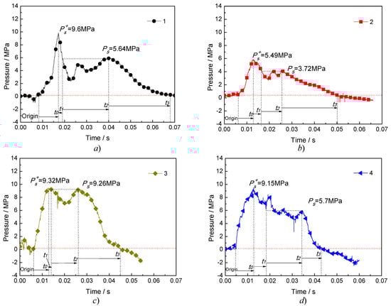
Figure 8.
Pressure–time curve at a certain distance outside the blasting tube in four tests.
It can be seen from Figure 8 and Table 2 that the peak pressure of the impact pressure curve shows the same regularity as the peak pressure in the blasting tube in the four tests, and the pressure function model (20) fits well with the pressure curve obtained by the tests, indicating that the pressure function model can be used to express the phase change jet impact pressure curve of a liquid carbon dioxide blasting system. The time from to was 0.008894 s, 0.00668 s, 0.00673 s and 0.00816 s, respectively. The rate of pressure rise directly reflects the rate of high-pressure fluids working on the outside world. The pressure increase rates at 0.23 m in the four tests was 1.07 GPa/s, 0.82 GPa/s, 1.38 GPa/s, and 1.12 GPa/s, respectively. For in the pressure curve, it can be smaller than the increasing peak pressure , or equal to , which is related to the thermodynamic characteristics and phase transition process in the blast tube. It can be seen from Figure 8 that the pressure of is longer, which is 0.021 s, 0.009 s, 0.013 s and 0.016 s, respectively. This process can be regarded as a stable loading process of jet impact, which represents that the phase changed jet impact of the liquid carbon dioxide blasting system. In the pressure quasi-static process, the impulse of the jet represents the energy of the jet impact and has the same regularity as the energy in the burst.
From the above analysis, the process of phase change of liquid carbon dioxide blasting system includes two main processes: dynamic loading process and quasi-static loading process.
3.3. Pressure Decay Characteristic
The damage of the liquid carbon dioxide blasting system to the target was mainly achieved by the jet impact pressure and the quasi-static action of the high-pressure gas under the sealed condition. The jet impact and impulse are the main factors. The pressure function and impulse variation of the jet have been discussed in the previous section. Combined with the TNT equivalent of the liquid carbon dioxide blasting system, the authors will discuss the impact pressure characteristics and attenuation characteristics at different distances.
TNT equivalent ratio is an important parameter to measure the power of explosives. It has important research significance for anti-explosive structure design, safety distance, and explosion accident. At present, through theoretical calculations and regression analysis of laboratory data, the peak pressure of TNT explosives’ shock wave with the attenuation law of propagation distance has the following analytical expression [36]:
where: is the peak pressure, MPa; is the contrast distance; is the TNT dose, kg; and is the distance from the blast, m.
For the non-ideal explosion source of liquid carbon dioxide blasting system, a TNT equivalent can be used instead of TNT dose ω to calculate the peak pressure of different contrast distance . By comparing the actual data of the same contrast distance under laboratory conditions, the pressure decay characteristics of the liquid carbon dioxide blasting system were analyzed. Table 3 gives the average distribution of the incident peak pressures at different contrast distances for the above four tests. The explosive energies of the four tests were 142.233 kJ, 124.372 kJ, 147.723 kJ and 136.725 kJ, respectively. TNT equivalents were 30.85 g TNT, 26.98g TNT, 32.04 g TNT, and 29.66g TNT, with an average of 29.88g TNT. Figure 9 shows that the peak pressure test value fit curve and theoretical calculated value curve at different distances and contrast distances (since the liquid carbon dioxide blasting system is a symmetrical jet exit, the measured peak pressure is ideally 1/2 of the total pressure, so it corresponds to the peak pressure of TNT, which is also taken as 1/2 of the theoretical calculation).
Table 3.
Peak pressure test values and theoretical calculation values at different distances and contrast distances.
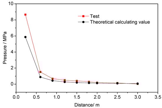
Figure 9.
Peak pressure test value fit curve and theoretically calculated value curve at different distances.
It can be seen from Table 3 and Figure 9 that the peak pressure of the liquid carbon dioxide blasting system is significantly larger than the theoretical pressure peak of the TNT overpressure, which is due to the influence of the jet pressure at a certain distance after the explosion.
The peak pressure from 0.23 m to 0.6 m was reduced from 8.653 MPa to 1.515 MPa. This rapid decrease was due to the rapid decrease of the jet velocity of the high-pressure fluid, which caused the peak pressure to decrease. It can be seen from the analysis of the velocity decay law in Section 3.1. The initial length of the circular turbulent jet was 0.136 m, and the distance has the same jet velocity. The jet with a centering distance of 0.23–0.6m was in the transition section and the main section of the circular turbulent jet. When the jet exceeded the main section, the influence of the jet gradually decreased, and the speed decreasing trend tended to be gentle. However, the peak pressure was also affected by the explosion shock wave. Therefore, the core distance was 0.6 m to 2.5 m, and the peak pressure decreased. The error in theoretical calculations was reduced. When the distance exceeded 2.5 m, the jet had no effect on the pressure, and, at this time, only the overpressure generated by the shock wave action. Based on the above analysis, it can be considered that the impact pressure field of the liquid carbon dioxide blasting system can be divided into three regions, namely, the explosion jet impact zone, the jet edge zone, and the shock wave action zone.
In order to visually and qualitatively describe the attenuation characteristics of the impact pressure of liquid carbon dioxide blasting system, based on the TNT equivalent, the TNT reference equation function relationship was used to compare and evaluate the impact pressure attenuation relationship of the liquid carbon dioxide blasting system impact pressure reference function. According to the theory of explosion similarity, when TNT explodes in the air, it has the same peak pressure at the same contrast distance and satisfies a certain functional relationship [29]:
and let ∆P be the nth degree polynomial of ∛ω/r; then, it can be expanded to:
where are undetermined coefficients, and a0 = 0 is determined by the boundary condition, and the TNT explosive shock wave peak pressure equation.
Using the test peak pressure data values in Table 3, using the least-squares principle to fit the data, the pressure–contrast distance equations and curves of the liquid carbon dioxide blasting system were obtained, and the pressure–contrast distance equation curve of the theoretical calculation equation was obtained—for comparison, as shown in Figure 10.
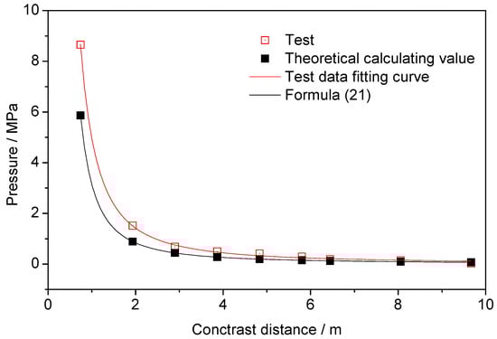
Figure 10.
Comparison of liquid carbon dioxide blasting system and TNT pressure–contrast distance curve.
The pressure–contrast distance fitting equation for the liquid carbon dioxide blasting system was shown in the following equation, with R2 being 0.96:
It can be seen from the above fitting equation that the jet impact pressure of the liquid carbon dioxide blasting system accords with the functional relationship.
4. Conclusions
In this paper, the characteristics of high-pressure fluid impingement pressure field in liquid carbon dioxide blasting system were measured. The phase transition jet velocity attenuation characteristics of liquid carbon dioxide blasting system were analyzed. The positive phase pressure response characteristics and pressure decay characteristics of blasting tube were discussed. The main conclusions obtained were:
(1) Based on the mechanism analysis of phase transition kinetics, the initial jet velocity of the four experiments was calculated to be 469.93 m/s, 338.87 m/s, 496.32 m/s, and 419.81 m/s; the rationality of results were verified by the Bernoulli equation.
(2) Simplifying and mathematically analyzing the test data for five stages of the ideal liquid carbon dioxide blasting system jet impact pressure curve, and obtaining the general expression of the positive phase pressure–time function, and four subtest pressure–time history function parameters were given.
(3) Analyzing and discussing the impact pressure characteristics and attenuation characteristics at different distances, the impact pressure field of the liquid carbon dioxide blasting system can be divided into three areas: the explosive jet impact zone, the jet edge zone and the shock wave action zone, and the pressure–contrast distance fitting equation of the liquid carbon dioxide blasting system were given.
Author Contributions
K.Z and G.R. conceived and designed the experiments; B.K. and Y.Z. performed the experiments; Y.Z. and J.S. analyzed the data; K.Z. contributed reagents/materials/analysis tools; B.K. wrote the paper.
Funding
This work was supported by the China Postdoctoral Science Foundation (No. 2018M632936), the Fundamental Research Funds for the Central Universities (WUT: 2019IVA092) and funded by the Research Fund of the State Key Laboratory of Coal Resources and Safe Mining, CUMT(SKLCRSM19KF020).
Conflicts of Interest
The authors declare no conflict of interest.
References
- Weir, P.; Edwards, J.H. Mechanical loading and Cardox revolutionize an old mine. Coal Age 1928, 33, 288–290. [Google Scholar]
- Lu, T.K.; Wang, Z.F.; Yang, H.M.; Yuan, P.J.; Han, Y.B.; Sun, X.M. Improvement of coal seam gas drainage by under-panel cross-strata stimulation using highly pressurized gas. Int. J. Rock Mech. Min. Sci. 2015, 77, 300–312. [Google Scholar] [CrossRef]
- Wilson, H.H. Coal augers: Development and application underground. Trans. Inst. Min. Eng. 1954, 113, 524–539. [Google Scholar]
- Clairet, J. Use of Cardox in coal mining in Sarre. Rev. Industrie Miner. 1952, 33, 846–854. [Google Scholar]
- Yang, X.; Wen, G.; Sun, H.; Li, X.; Lu, T.; Dai, L.; Cao, J.; Li, L. Environmentally friendly techniques for high gas content thick coal seam stimulation—multi-discharge CO2 fracturing system. J. Nat. Gas Sci. Eng. 2019, 61, 71–82. [Google Scholar] [CrossRef]
- Ke, B.; Zhou, K.; Xu, C.; Ren, G.; Jiang, T. Thermodynamic properties and explosion energy analysis of carbon dioxide blasting systems. Min. Technol. 2019, 128, 39–50. [Google Scholar] [CrossRef]
- Vidanovic, N.; Ognjanovic, S.; Ilincic, N.; Ilic, N.; Tokalic, R. Application of unconventional methods of underground premises construction in coal mines. Tech. Technol. Educ. Manag. 2011, 6, 861–865. [Google Scholar]
- Pantovic, R.; Milic, V.; Stojadinovic, S. Consideration of possibilities for application of CARDOX method in purpose of improvement of coal fragmentation. Proceedings of IOC 2002: 34 th International October Conference on Mining and Metallurgy, Bor Lake, Yugoslavia, 30 September–3 October 2002; pp. 131–135. [Google Scholar]
- Zou, D.; Panawalage, S. Passive and Triggered Explosion Barriers in Underground Coal Mines—A Literature Review of Recent Research; Natural Resources Canada: Ottawa, ON, Canada, 2001. [Google Scholar]
- Zhang, W.; Zhang, D.; Wang, H.; Cheng, J. Comprehensive Technical Support for High-Quality Anthracite Production: A Case Study in the Xinqiao Coal Mine, Yongxia Mining Area, China. Minerals 2015, 5, 919–935. [Google Scholar] [CrossRef]
- Pesch, R.; Robertson, A. Drilling and Blasting for Underground Space. In Proceedings of the EXPLO Conference, Wollongong, Australia, 3–4 September 2007; pp. 189–193. [Google Scholar]
- Tampekis, S.; Samara, F.; Sakellariou, S.; Sfougaris, A.; Christopoulou, O. An eco-efficient and economical optimum evaluation technique for the forest road networks: The case of the mountainous forest of Metsovo, Greece. Environ. Monit. Assess. 2018, 190, 134. [Google Scholar] [CrossRef]
- Parsakhoo, A.; Lotfalian, M. Demolition agent selection for rock breaking in mountain region of hyrcanian forests. Res. J. Environ. Sci. 2009, 3, 384–391. [Google Scholar] [CrossRef][Green Version]
- Bajpayee, T.; Rehak, T.; Mowrey, G.; Ingram, D. Blasting injuries in surface mining with emphasis on flyrock and blast area security. J. Saf. Res. 2004, 35, 47–57. [Google Scholar] [CrossRef] [PubMed]
- Durga, S.; Swetha, R. Disaster Prevention and Control Management. Procedia Earth Planet. Sci. 2015, 11, 516–523. [Google Scholar] [CrossRef][Green Version]
- Chen, H.D.; Wang, Z.F.; Chen, X.E.; Chen, X.J.; Wang, L.G. Increasing permeability of coal seams using the phase energy of liquid carbon dioxide. J. CO2 Util. 2017, 19, 112–119. [Google Scholar] [CrossRef]
- He, W.R.; He, F.L.; Zhang, K.; Zhao, Y.Q.; Zhu, H.Z. Increasing Permeability of Coal Seam and Improving Gas Drainage Using a Liquid Carbon Dioxide Phase Transition Explosive Technology. Adv. Civ. Eng. 2018. [Google Scholar] [CrossRef]
- Kang, J.H.; Zhou, F.B.; Qiang, Z.Y.; Zhu, S.J. Evaluation of gas drainage and coal permeability improvement with liquid CO2 gasification blasting. Adv. Mech. Eng. 2018, 10, 15. [Google Scholar] [CrossRef]
- Wang, Z.F.; Sun, X.M.; Lu, T.K.; Han, Y.B. Experiment Research on Strengthening Gas Drainage Effect with Fracturing Technique by Liquid CO2 Phase Transition. J. Henan Polytech. Univ. 2015, 34, 1–5. (In Chinese) [Google Scholar]
- Zhao, L.P. Technology of Liquid Carbon Dioxide Deep Hole Blasting Enhancing Permeability in Coal Seam. Saf. Coal Mines 2013, 44, 76–78. (In Chinese) [Google Scholar]
- Huo, Z.G. New Technology of Carbon Dioxide Fracturer Applied to Deep Borehole Pre-Cracking Blasting for Seam Permeability Improvement. Coal Sci. Technol. 2015, 43, 80–83. (In Chinese) [Google Scholar]
- Dong, Q.X. , Wang, Z.F.; Han, Y.B., Sun, X.M. Research on TNT Equivalent of Liquid CO2 Phase–Transition Fracturing. China Saf. Sci. J. 2014, 24, 84–88. (In Chinese) [Google Scholar]
- Span, R.; Wagner, W. A new equation of state for carbon dioxide covering the fluid region from the triple-point temperature to 1100 K at pressures up to 800 MPa. J. Phys. Chem. Ref. Data 1996, 25, 1509–1596. [Google Scholar] [CrossRef]
- Davies, B.; Hawkes, I. The Mechanics of Blasting Strata Using the Cardox and Air Blasting Systems; Toothill Press: London, UK, 1984; pp. 461–467. [Google Scholar]
- Zhang, Y.; Deng, J.; Ke, B.; Deng, H.; Li, J. Experimental Study on Explosion Pressure and Rock Breaking Characteristics under Liquid Carbon Dioxide Blasting. Adv. Civ. Eng. 2018, 2018, 9. [Google Scholar] [CrossRef]
- Zhang, Y.A.; Deng, J.R.; Deng, H.W.; Ke, B. Peridynamics simulation of rock fracturing under liquid carbon dioxide blasting. Int. J. Damage Mech. 2019, 28, 1038–1052. [Google Scholar] [CrossRef]
- Hu, G.Z.; He, W.R.; Sun, M. Enhancing coal seam gas using liquid CO2 phase-transition blasting with cross-measure borehole. J. Nat. Gas Sci. Eng. 2018, 60, 164–173. [Google Scholar] [CrossRef]
- Chen, Y.; Zhang, H.W.; Zhu, Z.J.; Ren, T.X.; Cao, C.; Zhu, F.; Li, Y.P. A new shock-wave test apparatus for liquid CO2 blasting and measurement analysis. Trans. Inst. Meas. Control 2019, 52, 399–408. [Google Scholar] [CrossRef]
- Zhang, W.; Xu, K.L.; Lei, Y.; Zhang, B.L. Evolutionary Features in Damage and Destruction of Gas-Rich Coal Seam by CO2 Phase-transition Blasting. Ekoloji 2018, 27, 1605–1613. [Google Scholar]
- Zhu, W.C.; Gai, D.; Wei, C.H.; Li, S.G. High-pressure air blasting experiments on concrete and implications for enhanced coal gas drainage. J. Nat. Gas Sci. Eng. 2016, 36, 1253–1263. [Google Scholar] [CrossRef]
- Sun, K.; Xin, L.; Wang, T.; Wang, J. Simulation research on law of coal fracture caused by supercritical CO2 explosion. J. China Univ. Min. Technol. 2017, 46, 501–506. [Google Scholar]
- Gao, F.; Leihu, T.; Zhou, K.-P.; Yanan, Z.; Ke, B. Mechanism Analysis of Liquid Carbon Dioxide Phase Transition for Fracturing Rock Masses. Energies 2018, 11, 2909. [Google Scholar] [CrossRef]
- Zhou, Y. Study on the Mechanism and Damage Effect of CO2 Boiling Liquid Expanding Vapor Explosion in CO2 Flooding; Beijing Institute of Technology: Beijing, China, 2015. (In Chinese) [Google Scholar]
- Papanicolaou, P.N.; List, E.J. Investigations of round vertical turbulent buoyant jets. J. Fluid Mech. 1988, 195, 341–391. [Google Scholar] [CrossRef]
- Persson, P.-A.; Holmberg, R.; Lee, J. Rock Blasting and Explosives Engineering; CRC Press: Boca Raton, FL, USA, 2018. [Google Scholar]
- Kinney, G.F.; Graham, K.J. Explosive Shocks in Air, 2nd ed.; Springer Science & Business Media: Berlin, Germany, 2013; pp. 18–49. [Google Scholar]


© 2019 by the authors. Licensee MDPI, Basel, Switzerland. This article is an open access article distributed under the terms and conditions of the Creative Commons Attribution (CC BY) license (http://creativecommons.org/licenses/by/4.0/).