A Novel Integrated Topology to Interface Electric Vehicles and Renewable Energies with the Grid

 ,
,  ,
,  , and
, and
Abstract
:1. Introduction
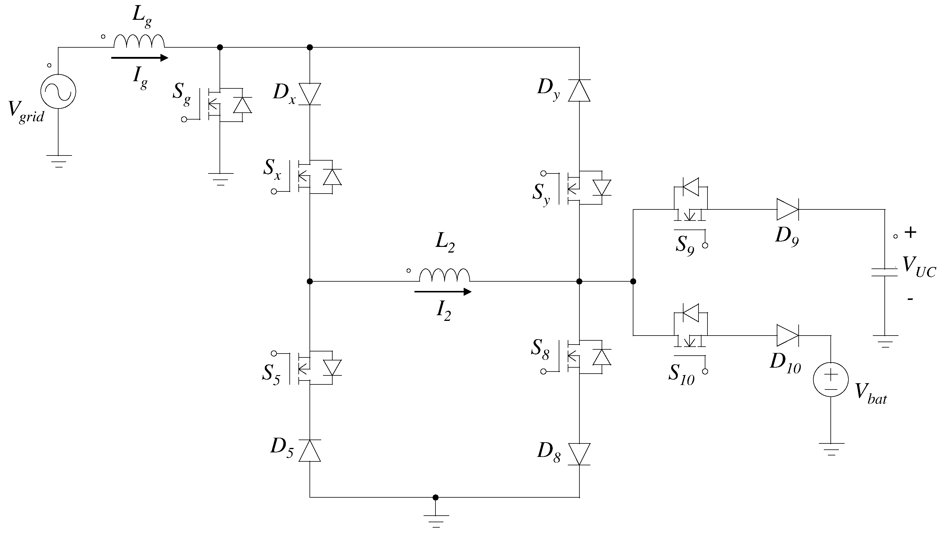
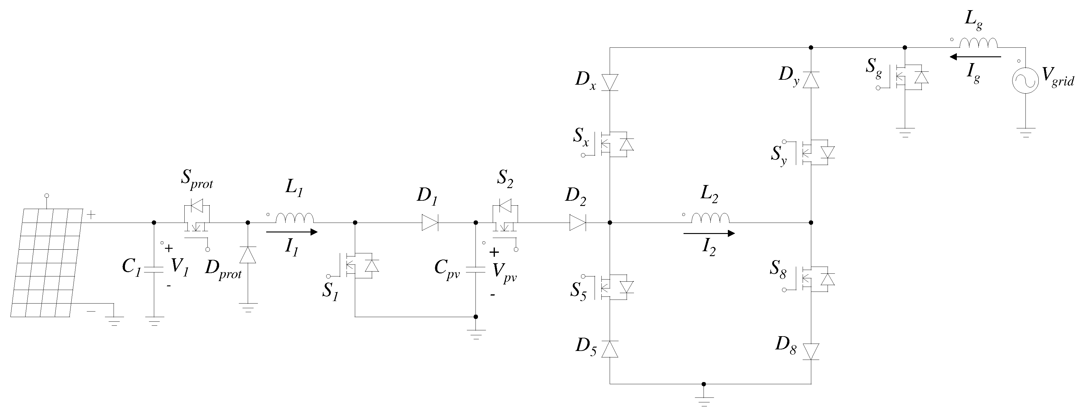
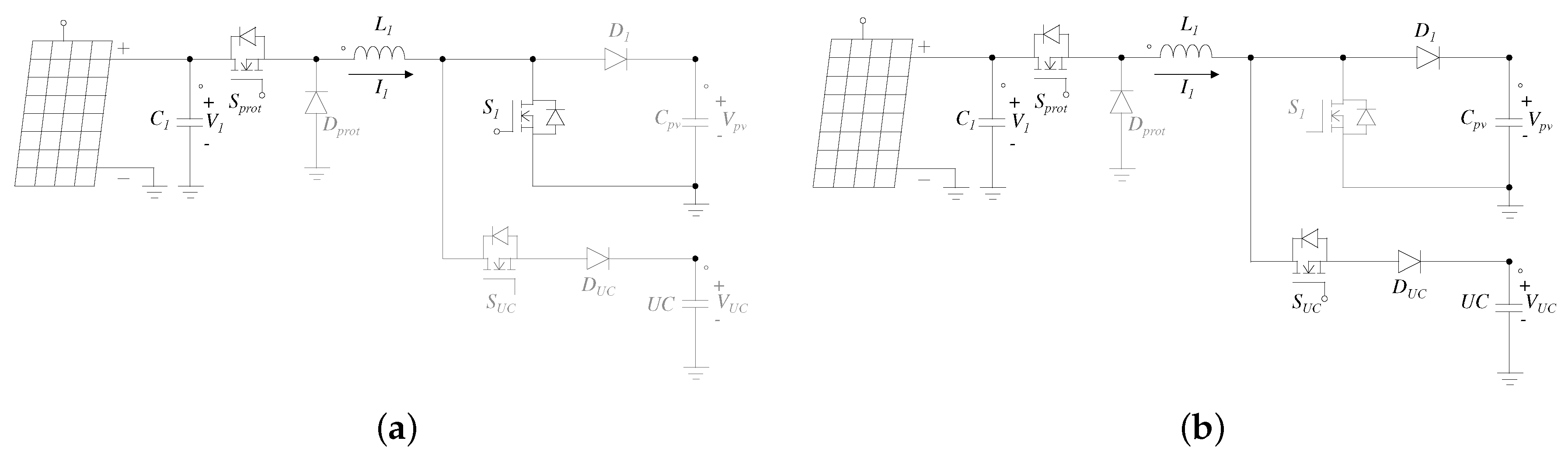
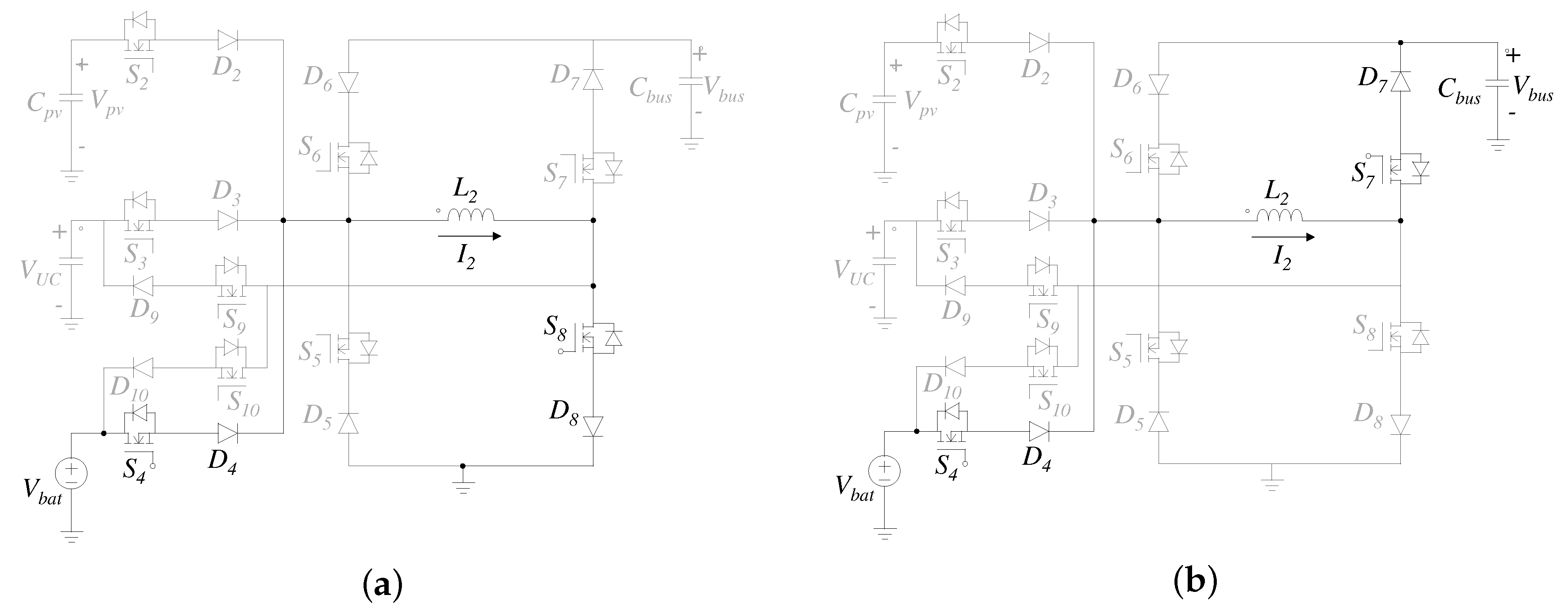
2. Operation and Analysis of the Converter
3. Design of the Converter
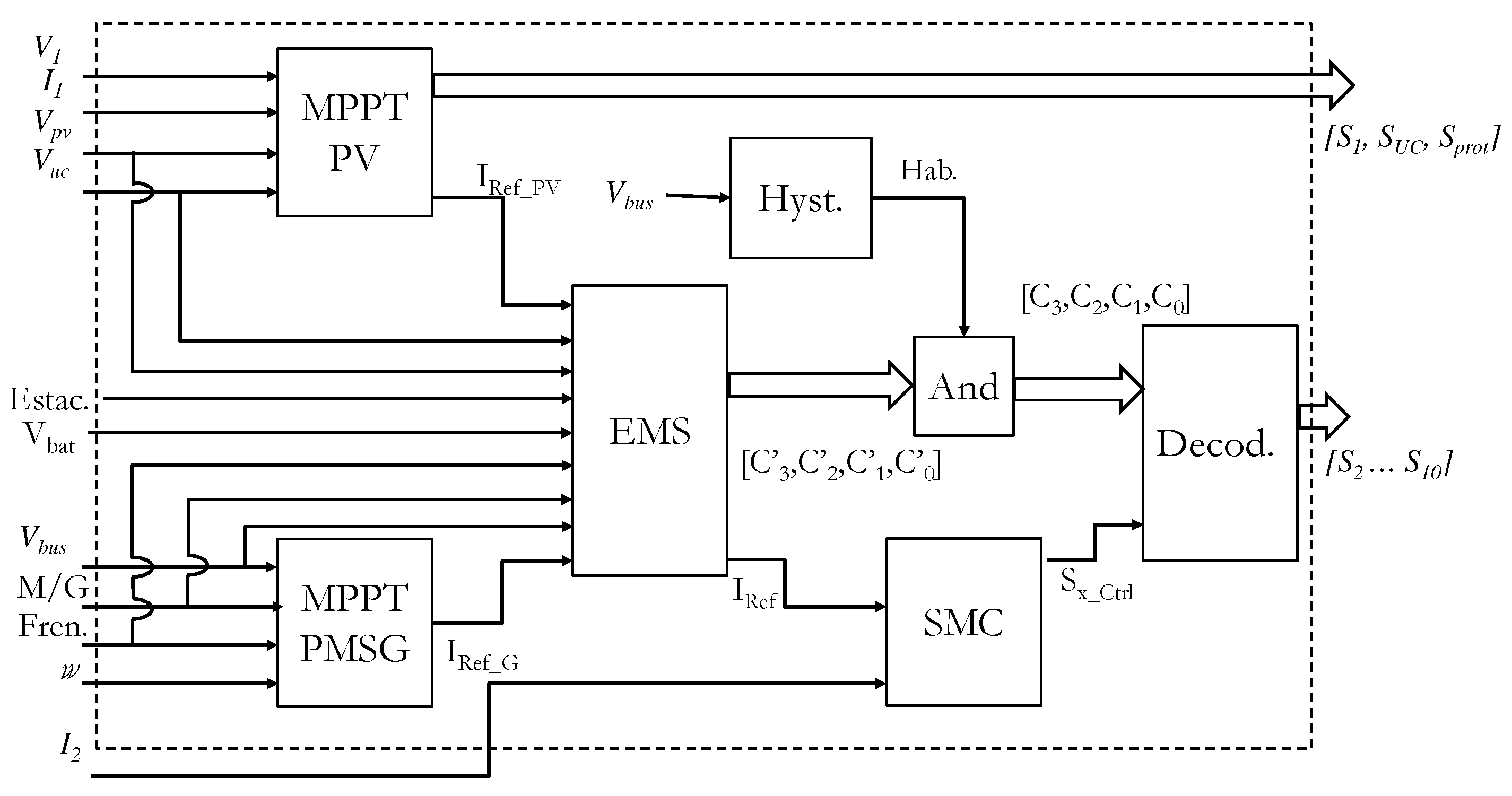
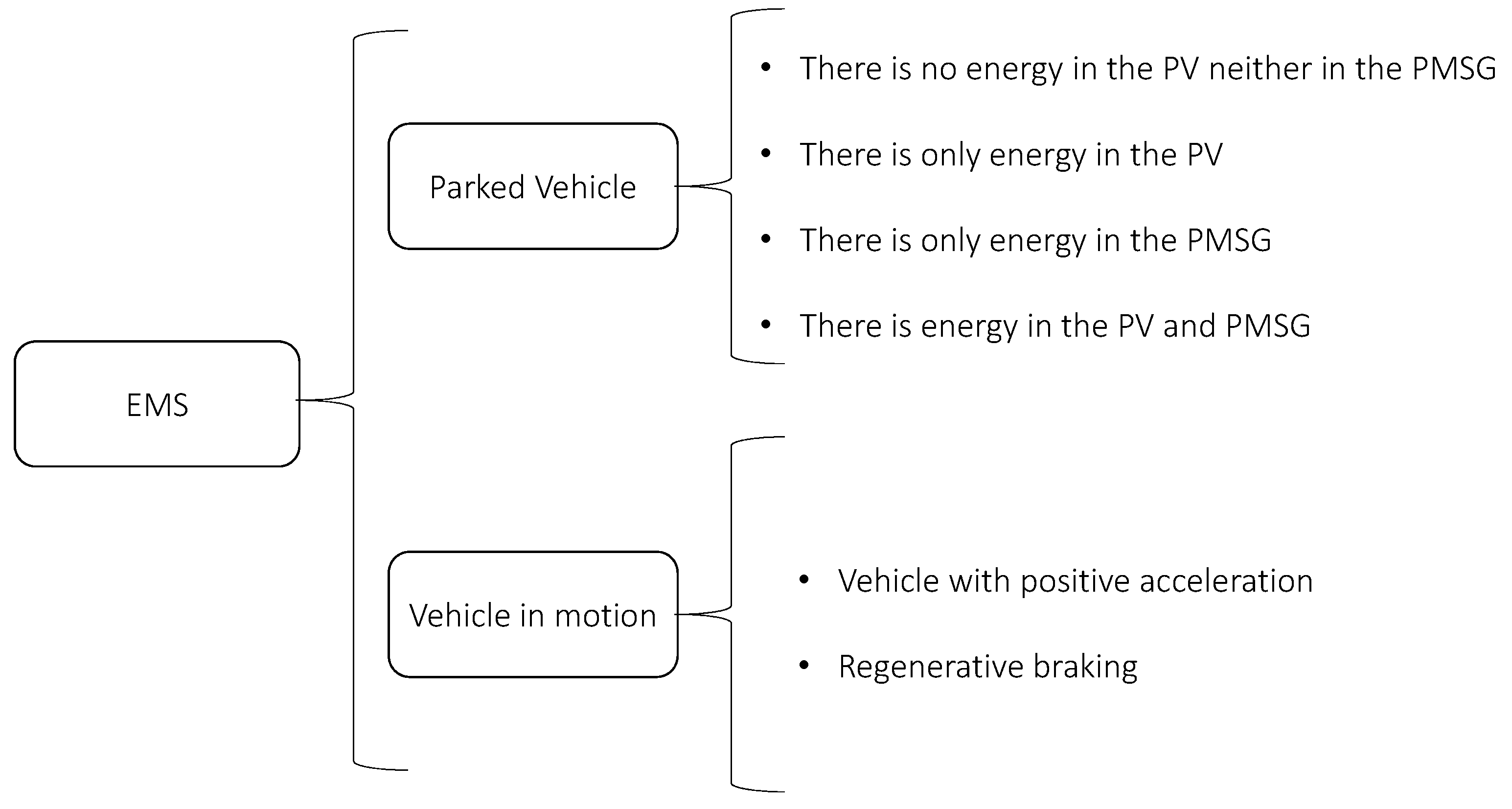
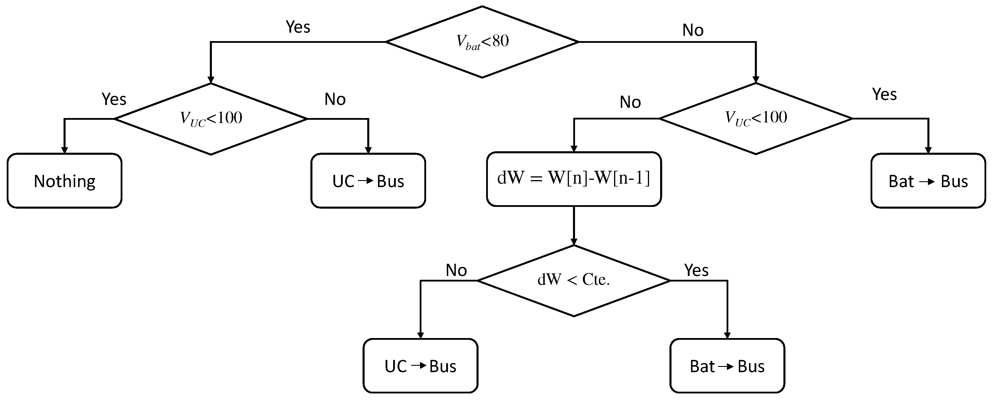
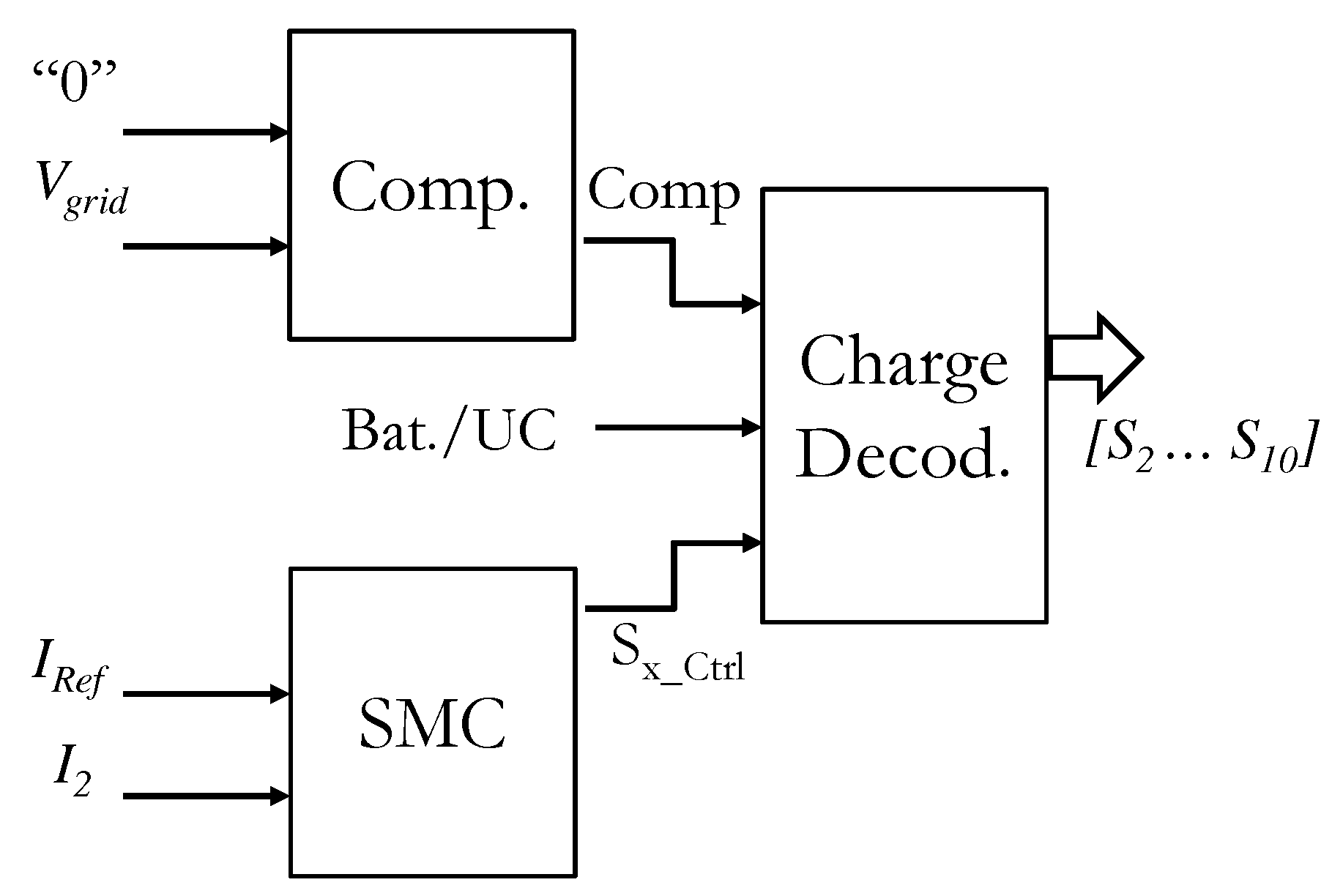
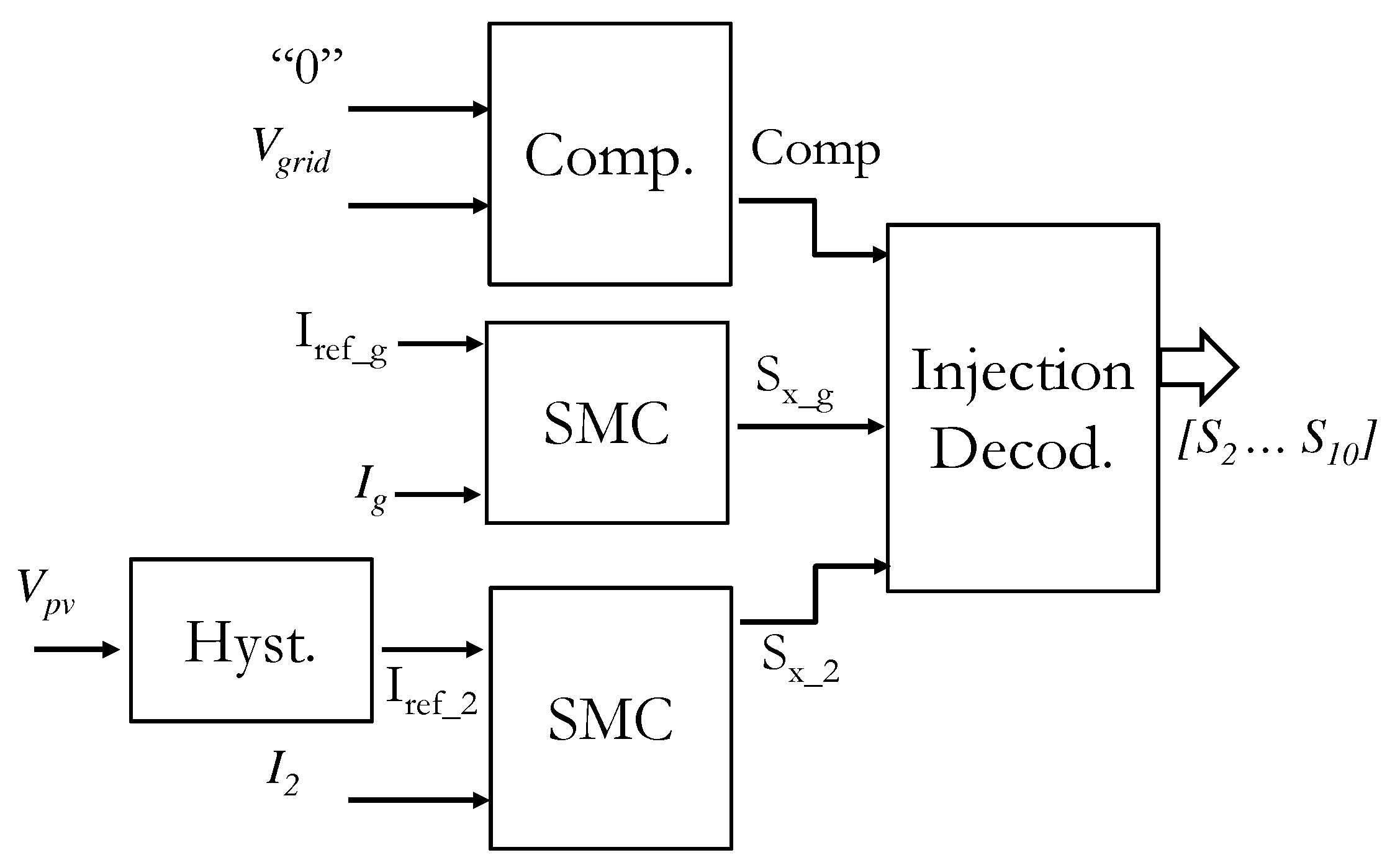
4. Control Strategy
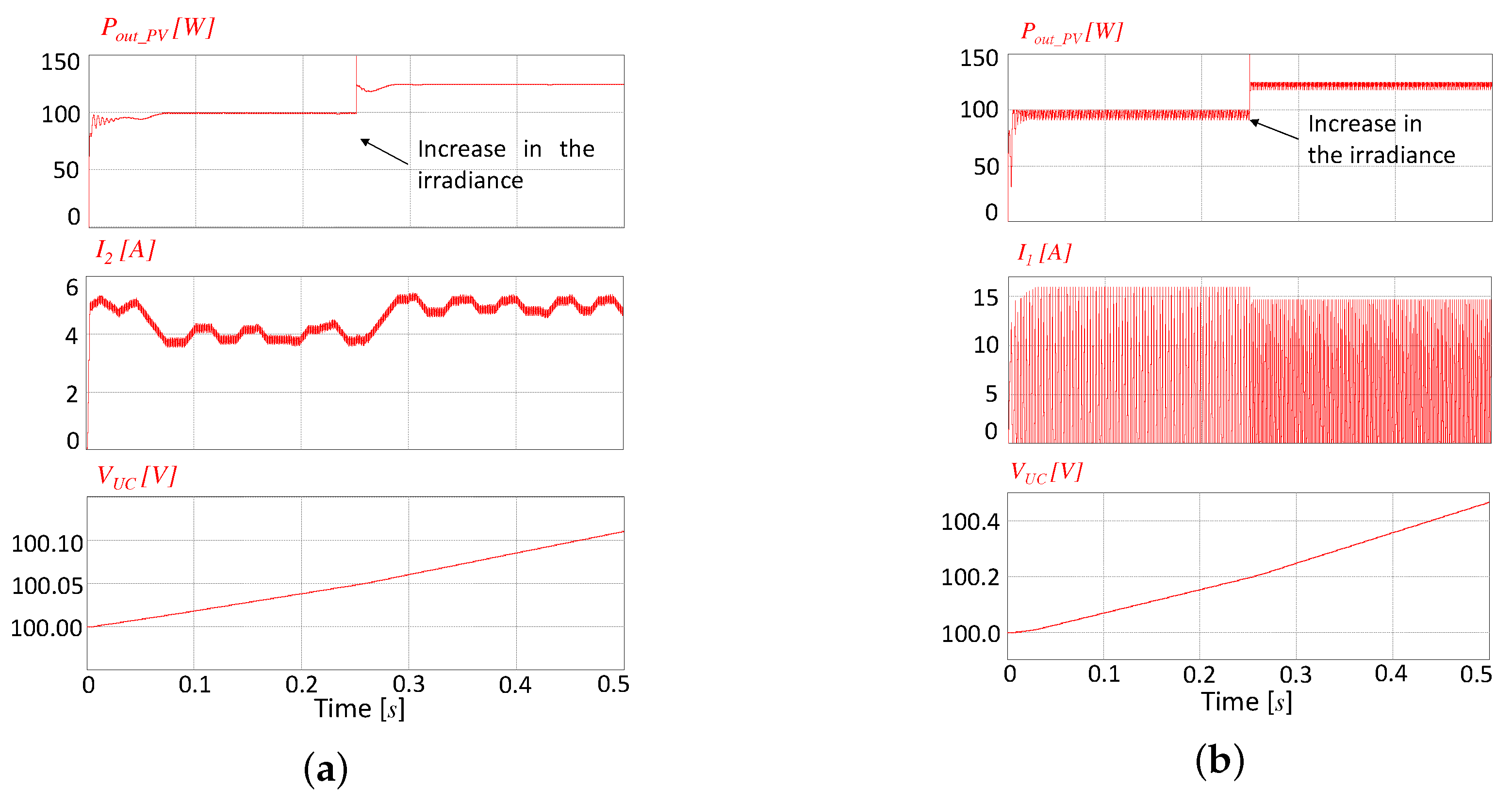
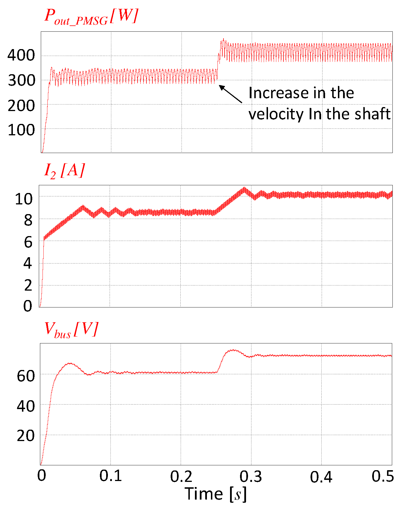
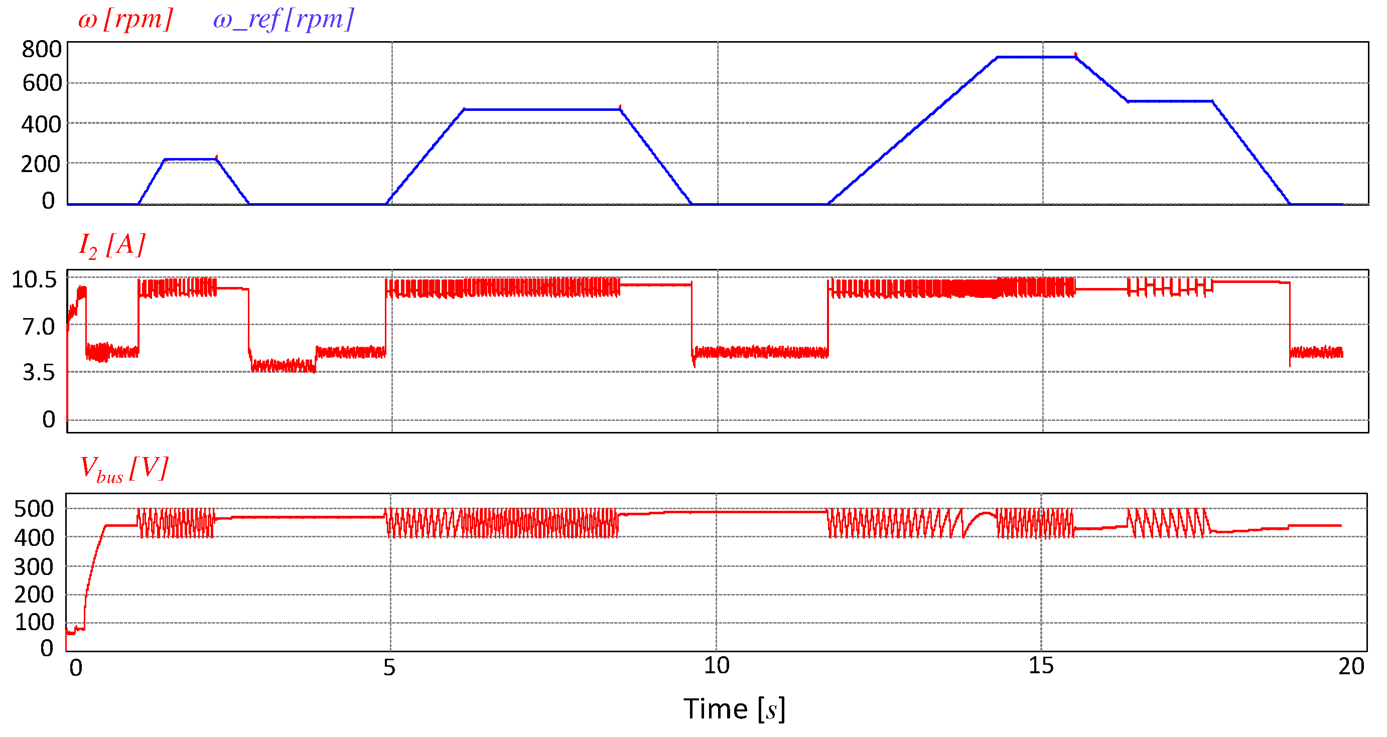
5. Simulation Results
6. Conclusions
Author Contributions
Funding
Conflicts of Interest
References
- Solaymani, S. CO2 emissions patterns in 7 top carbon emitter economies: The case of transport sector. Energy 2019, 168, 989–1001. [Google Scholar] [CrossRef]
- Khaligh, A.; Li, Z. Battery, ultracapacitor, fuel cell, and hybrid energy storage systems for electric, hybrid electric, fuel cell, and plug-in hybrid electric vehicles: State of the art. IEEE Trans. Veh. Technol. 2010, 59, 2806–2814. [Google Scholar] [CrossRef]
- Dusmez, S.; Hasanzadeh, A.; Khaligh, A. Comparative analysis of bidirectional three-level DC-DC converter for automotive applications. IEEE Trans. Ind. Electron. 2014, 62, 3305–3315. [Google Scholar] [CrossRef]
- Shen, J.; Dusmez, S.; Khaligh, A. Optimization of sizing and battery cycle life in battery/ultracapacitor hybrid energy storage systems for electric vehicle applications. IEEE Trans. Ind. Inform. 2014, 10, 2112–2121. [Google Scholar] [CrossRef]
- Lu, S.; Corzine, K.A.; Ferdowsi, M. A new battery/ultracapacitor energy storage system design and its motor drive integration for hybrid electric vehicles. IEEE Trans. Veh. Technol. 2007, 56, 1516–1523. [Google Scholar] [CrossRef]
- Dusmez, S.; Khaligh, A. A supervisory power-splitting approach for a new ultracapacitor–battery vehicle deploying two propulsion machines. IEEE Trans. Ind. Inform. 2014, 10, 1960–1971. [Google Scholar] [CrossRef]
- Emadi, A.; Williamson, S. Fuel cell vehicles: Opportunities and challenges. In Proceedings of the IEEE Power Engineering Society General Meeting, Denver, CO, USA, 6–10 June 2004; pp. 1640–1645. [Google Scholar]
- Aso, S.; Kizaki, M.; Nonobe, Y. Development of fuel cell hybrid vehicles in Toyota. In Proceedings of the 2007 Power Conversion Conference-Nagoya, Nagoya, Japan, 2–5 April 2007; pp. 1606–1611. [Google Scholar]
- Rajashekara, K. Present status and future trends in electric vehicle propulsion technologies. IEEE J. Emerg. Sel. Top. Power Electron. 2013, 1, 3–10. [Google Scholar] [CrossRef]
- Ding, Z.; Yang, C.; Zhang, Z.; Wang, C.; Xie, S. A novel soft-switching multiport bidirectional DC-DC converter for hybrid energy storage system. IEEE Trans. Power Electron. 2013, 29, 1595–1609. [Google Scholar] [CrossRef]
- Dusmez, S.; Li, X.; Akin, B. A new multiinput three-level DC-DC converter. IEEE Trans. Power Electron. 2015, 31, 1230–1240. [Google Scholar] [CrossRef]
- Reddi, N.; Ramteke, M.; Suryawanshi, H. Dual-Input Single-Output Isolated Resonant Converter with Zero Voltage Switching. Electronics 2018, 7, 96. [Google Scholar] [CrossRef]
- Lu, S.; Corzine, K.A.; Ferdowsi, M. A unique ultracapacitor direct integration scheme in multilevel motor drives for large vehicle propulsion. IEEE Trans. Veh. Technol. 2007, 56, 1506–1515. [Google Scholar] [CrossRef]
- Camara, M.B.; Gualous, H.; Gustin, F.; Berthon, A.; Dakyo, B. DC-DC converter design for supercapacitor and battery power management in hybrid vehicle applications—Polynomial control strategy. IEEE Trans. Ind. Electron. 2009, 57, 587–597. [Google Scholar] [CrossRef]
- Kollimalla, S.K.; Mishra, M.K.; Narasamma, N.L. Design and analysis of novel control strategy for battery and supercapacitor storage system. IEEE Trans. Sustain. Energy 2014, 5, 1137–1144. [Google Scholar] [CrossRef]
- Tani, A.; Camara, M.B.; Dakyo, B. Energy management based on frequency approach for hybrid electric vehicle applications: Fuel-cell/lithium-battery and ultracapacitors. IEEE Trans. Veh. Technol. 2012, 61, 3375–3386. [Google Scholar] [CrossRef]
- Zandi, M.; Payman, A.; Martin, J.P.; Pierfederici, S.; Davat, B.; Meibody-Tabar, F. Energy management of a fuel cell/supercapacitor/battery power source for electric vehicular applications. IEEE Trans. Veh. Technol. 2010, 60, 433–443. [Google Scholar] [CrossRef]
- Payman, A.; Pierfederici, S.; Meibody-Tabar, F.; Davat, B. An adapted control strategy to minimize DC-bus capacitors of a parallel fuel cell/ultracapacitor hybrid system. IEEE Trans. Power Electron. 2009, 26, 3843–3852. [Google Scholar] [CrossRef]
- Nejabatkhah, F.; Danyali, S.; Hosseini, S.H.; Sabahi, M.; Niapour, S.M. Modeling and control of a new three-input DC-DC boost converter for hybrid PV/FC/battery power system. IEEE Trans. Power Electron. 2011, 27, 2309–2324. [Google Scholar] [CrossRef]
- Khaligh, A. A multiple-input DC-DC positive buck-boost converter topology. In Proceedings of the 2008 Twenty-Third Annual IEEE Applied Power Electronics Conference and Exposition, Austin, TX, USA, 24–28 February 2008; pp. 1522–1526. [Google Scholar]
- Peng, F.Z.; Shen, M.; Holland, K. Application of Z-source inverter for traction drive of fuel cell—Battery hybrid electric vehicles. IEEE Trans. Power Electron. 2007, 22, 1054–1061. [Google Scholar] [CrossRef]
- Solero, L.; Lidozzi, A.; Pomilio, J.A. Design of multiple-input power converter for hybrid vehicles. IEEE Trans. Power Electron. 2005, 20, 1007–1016. [Google Scholar] [CrossRef]
- Akar, F.; Tavlasoglu, Y.; Ugur, E.; Vural, B.; Aksoy, I. A bidirectional nonisolated multi-input DC-DC converter for hybrid energy storage systems in electric vehicles. IEEE Trans. Veh. Technol. 2015, 65, 7944–7955. [Google Scholar] [CrossRef]
- Hintz, A.; Prasanna, U.R.; Rajashekara, K. Novel modular multiple-input bidirectional DC-DC power converter (MIPC) for HEV/FCV application. IEEE Trans. Ind. Electron. 2014, 62, 3163–3172. [Google Scholar] [CrossRef]
- Ahrabi, R.R.; Ardi, H.; Elmi, M.; Ajami, A. A novel step-up multiinput DC-DC converter for hybrid electric vehicles application. IEEE Trans. Power Electron. 2016, 32, 3549–3561. [Google Scholar] [CrossRef]
- Babaei, E.; Abbasi, O. Structure for multi-input multi-output DC-DC boost converter. IET Power Electron. 2016, 9, 9–19. [Google Scholar] [CrossRef]
- Nahavandi, A.; Hagh, M.T.; Sharifian, M.B.B.; Danyali, S. A nonisolated multiinput multioutput DC-DC boost converter for electric vehicle applications. IEEE Trans. Power Electron. 2014, 30, 1818–1835. [Google Scholar] [CrossRef]
- López, H.; Rodríguez-Reséndiz, J.; Guo, X.; Vázquez, N.; Carrillo-Serrano, R.V. Transformerless common-mode current-source inverter grid-connected for PV applications. IEEE Access 2018, 6, 62944–62953. [Google Scholar] [CrossRef]
- Zsiborács, H.; Hegedusné Baranyai, N.; Csányi, S.; Vincze, A.; Pintér, G. Economic Analysis of Grid-Connected PV System Regulations: A Hungarian Case Study. Electronics 2019, 8, 149. [Google Scholar] [CrossRef]
- Mali, V.D.; Thorat, A.; Sawant, N.K. An Isolated Multiport Bidirectional DC-DC Converter for PV Battery System. In Proceedings of the 2018 Second International Conference on Inventive Communication and Computational Technologies (ICICCT), Coimbatore, India, 20–21 April 2018; pp. 302–306. [Google Scholar]
- Khatab, A.M.; Marei, M.I.; Elhelw, H.M. An Electric Vehicle Battery Charger Based on Zeta Converter Fed from a PV Array. In Proceedings of the 2018 IEEE International Conference on Environment and Electrical Engineering and 2018 IEEE Industrial and Commercial Power Systems Europe (EEEIC/I&CPS Europe), Palermo, Italy, 12–15 June 2018; pp. 1–5. [Google Scholar]
- Chen, X.; Pise, A.A.; Elmes, J.; Batarseh, I. Ultra-Highly Efficient Low Power Bi-directional Cascaded-Buck-Boost Converter for Portable PV-Battery-Devices Applications. IEEE Trans. Ind. Appl. 2019, 55, 3989–4000. [Google Scholar] [CrossRef]
- Liu, S.; Gao, Y.; Yang, L. Research on Application of Non-Isolated Three-Port Switching Boost Converter in Photovoltaic Power Generation System. Electronics 2019, 8, 746. [Google Scholar] [CrossRef]
- Chewale, M.A.; Wanjari, R.A.; Savakhande, V.B.; Sonawane, P.R. A Review on Isolated and Non-isolated DC-DC Converter for PV Application. In Proceedings of the 2018 International Conference on Control, Power, Communication and Computing Technologies (ICCPCCT), Kannur, India, 23–24 March 2018; pp. 399–404. [Google Scholar]
- Fahem, K.; Chariag, D.E.; Sbita, L. On-board bidirectional battery chargers topologies for plug-in hybrid electric vehicles. In Proceedings of the 2017 International Conference on Green Energy Conversion Systems (GECS), Hammamet, Tunisia, 23–25 March 2017; pp. 1–6. [Google Scholar]
- Rippel, W.E. Integrated Traction Inverter and Battery Charger Apparatus. U.S. Patent 4,920,475, 24 April 1990. [Google Scholar]
- Rippel, W.E.; Cocconi, A.G. Integrated Motor Drive and Recharge System. U.S. Patent 5,099,186, 24 March 1992. [Google Scholar]
- Cocconi, A.G. Combined Motor Drive and Battery Recharge System. U.S. Patent 5,341,075, 23 August 1994. [Google Scholar]
- Sul, S.K.; Lee, S.J. An integral battery charger for four-wheel drive electric vehicle. IEEE Trans. Ind. Appl. 1995, 31, 1096–1099. [Google Scholar]
- Hegazy, O.; Van Mierlo, J.; Lataire, P. Design and control of bidirectional DC/AC and DC/DC converters for plug-in hybrid electric vehicles. In Proceedings of the 2011 International Conference on Power Engineering, Energy and Electrical Drives, Malaga, Spain, 11–13 May 2011; pp. 1–7. [Google Scholar]
- De Sousa, L.; Silvestre, B.; Bouchez, B. A combined multiphase electric drive and fast battery charger for electric vehicles. In Proceedings of the 2010 IEEE Vehicle Power and Propulsion Conference, Lille, France, 1–3 September 2010; pp. 1–6. [Google Scholar]
- Lacroix, S.; Labouré, E.; Hilairet, M. An integrated fast battery charger for electric vehicle. In Proceedings of the 2010 IEEE Vehicle Power and Propulsion Conference, Lille, France, 1–3 September 2010; pp. 1–6. [Google Scholar]
- Haghbin, S.; Lundmark, S.; Alakula, M.; Carlson, O. An isolated high-power integrated charger in electrified-vehicle applications. IEEE Trans. Veh. Technol. 2011, 60, 4115–4126. [Google Scholar] [CrossRef]
- Subotic, I.; Levi, E. An integrated battery charger for EVs based on a symmetrical six-phase machine. In Proceedings of the 2014 IEEE 23rd International Symposium on Ind. Electron (ISIE), Istanbul, Turkey, 1–4 June 2014; pp. 2074–2079. [Google Scholar]
- Lee, Y.J.; Khaligh, A.; Emadi, A. Advanced integrated bidirectional AC/DC and DC/DC converter for plug-in hybrid electric vehicles. IEEE Trans. Veh. Technol. 2009, 58, 3970–3980. [Google Scholar]
- Chen, H.; Wang, X.; Khaligh, A. A single stage integrated bidirectional ac/dc and dc/dc converter for plug-in hybrid electric vehicles. In Proceedings of the 2011 IEEE Vehicle Power and Propulsion Conference, Chicago, IL, USA, 6–9 September 2011; pp. 1–6. [Google Scholar]
- Erb, D.C.; Onar, O.C.; Khaligh, A. An integrated bi-directional power electronic converter with multi-level AC-DC/DC-AC converter and non-inverted buck-boost converter for PHEVs with minimal grid level disruptions. In Proceedings of the 2010 IEEE Vehicle Power and Propulsion Conference, Lille, France, 1–3 September 2010; pp. 1–6. [Google Scholar]
- Kumar, G.; Sarojini, R.K.; Palanisamy, K.; Sanjeevikumar, P.; Holm-Nielsen, J.B. Large Scale Renewable Energy Integration: Issues and Solutions. Energies 2019, 12, 1996. [Google Scholar] [CrossRef]
- Mudhol, A.; Pius, P. Design and implementation of boost converter for photovoltaic systems. Int. J. Innov. Res. Elect. Electron. Instrum. Control Eng. 2016, 4, 110–114. [Google Scholar] [CrossRef]
- Hauke, B. Basic Calculation of Buck Converter’s Power Stages; Technical report, Texas, Tech. Rep. SLVA477, Dec; Texas Instruments: Dallas, TX, USA, 2011. [Google Scholar]
- Hauke, B. Application Report: Basic Calculation of a Boost Converter’s Power Stage; Texas Instruments: Dallas, TX, USA, 2014. [Google Scholar]
- Abbas, G.; Gu, J.; Farooq, U.; Abid, M.; Raza, A.; Asad, M.; Balas, V.; Balas, M. Optimized Digital Controllers for Switching-Mode DC-DC Step-Down Converter. Electronics 2018, 7, 412. [Google Scholar] [CrossRef]
- Sira-Ramirez, H.J.; Silva-Ortigoza, R. Control Design Techniques in Power Electronics Devices; Springer-Verlag: London, UK, 2006. [Google Scholar]
- Yang, Y.; Tan, S.C. Trends and Development of Sliding Mode Control Applications for Renewable Energy Systems. Energies 2019, 12, 2861. [Google Scholar] [CrossRef]
- Cucuzzella, M.; Rosti, S.; Cavallo, A.; Ferrara, A. Decentralized sliding mode voltage control in DC microgrids. In Proceedings of the 2017 American Control Conference (ACC), Seattle, WA, USA, 24–26 May 2017; pp. 3445–3450. [Google Scholar]
- Cucuzzella, M.; Lazzari, R.; Trip, S.; Rosti, S.; Sandroni, C.; Ferrara, A. Sliding mode voltage control of boost converters in DC microgrids. Control Eng. Pract. 2018, 73, 161–170. [Google Scholar] [CrossRef]
- Kim, S.K.; Lee, K.B. Robust DC-Link Voltage Tracking Controller with Variable Control Gain for Permanent Magnet Synchronous Generators. Electronics 2018, 7, 339. [Google Scholar] [CrossRef]
- Senthilnathan, K.; Annapoorani, I. Multi-port current source inverter for smart microgrid applications: A cyber physical paradigm. Electronics 2019, 8, 1. [Google Scholar] [CrossRef]


| Topology | Bidirectional | Transfer Directly between Sources | Extension to Multiport | Operation in Buck/Boost Mode | Interaction with the Grid | Number of Devices (n is Number of Inputs) |
|---|---|---|---|---|---|---|
| [22] | Yes | No | Yes | No | No | n inductors 2n switches |
| [23] | Yes | No | Yes | No | No | n inductors 2+n switches |
| [24] | Yes | Yes | Yes | Yes | No | n inductors 2n+2 switches |
| [25] | No | Yes | No | No | No | 2 inductors 4 switches |
| Proposed converter | Yes | Yes | Yes | Yes | Yes | 1 inductor 2n+4 switches |
| Transfer | Mode | Switches on | UC | |||
|---|---|---|---|---|---|---|
| 1. PV,UC | Yes | + | = | = | ||
| - | + | + | ||||
| 2. PV,UC | No | + | = | + | ||
| - | + | = |
| Transfer | Behavior | Mode | Switches on | UC | Bat | Bus | Steady-State | ||
|---|---|---|---|---|---|---|---|---|---|
| 3. BatBus | Boost | + | = | = | - | = | |||
| - | = | = | - | + | |||||
| 4. UCBus | Boost | + | = | - | = | = | |||
| - | = | - | = | + | |||||
| 5. PVBus | Boost | + | - | = | = | = | |||
| - | - | = | = | + | |||||
| 6. PVUC | Boost | + | - | = | = | = | |||
| - | - | + | = | = | |||||
| 7. PVBat | Boost | + | - | = | = | = | |||
| - | - | = | + | = | |||||
| 8. BatUC | Buck | + | = | + | - | = | |||
| - | = | + | = | = | |||||
| 9. BusBat | Buck | + | = | = | = | - | |||
| - | = | = | + | = | |||||
| 10. BusUC | Buck | + | = | + | = | - | |||
| - | = | + | = | = |
| Transfer | Behavior | [V] | [V] | [A] | [V] | [A] | D | f [kHz] | [mH] | [F] |
|---|---|---|---|---|---|---|---|---|---|---|
| 3. BatBus | Boost | 450 | 140 | 0.5 | 1 | 10 | 0.69 | 50 | 3.86 | 138 |
| 4. UCBus | Boost | 450 | 125 | 0.5 | 1 | 10 | 0.72 | 50 | 3.61 | 144 |
| 8. BatUC | Buck | 125 | 140 | 1 | - | - | - | 50 | 0.27 | - |
| 9. BusBat | Buck | 140 | 450 | 1 | - | - | - | 50 | 1.93 | - |
| 10. BusUC | Buck | 125 | 450 | 1 | - | - | - | 50 | 1.81 | - |
| Action | Buck Converter | Boost Converter |
|---|---|---|
| Model Obtention | ||
| Proposing the sliding surface | = S(-)
| = S(-)
|
| Obtaining the derivative of the sliding surface | ||
| Verify the existence condition ( > 0) | ||
| Verify the existence condition ( < 0) | ||
| Define the sign of the parameter S( <0) | S must be positive | S must be positive |
| Bat./UC | Comp | |||||||
|---|---|---|---|---|---|---|---|---|
| 0 | 0 | 0 | 0 | 1 | 0 | 0 | 1 | 1 |
| 0 | 0 | 1 | 1 | 0 | 0 | 0 | 1 | 1 |
| 0 | 1 | 0 | 0 | 0 | 1 | 0 | 1 | 0 |
| 0 | 1 | 1 | 0 | 0 | 1 | 0 | 1 | 0 |
| 1 | 0 | 0 | 0 | 0 | 1 | 1 | 0 | 1 |
| 1 | 0 | 1 | 1 | 0 | 0 | 0 | 1 | 1 |
| 1 | 1 | 0 | 0 | 1 | 0 | 1 | 0 | 0 |
| 1 | 1 | 1 | 0 | 1 | 0 | 1 | 0 | 0 |
| Comp | ||||||||
|---|---|---|---|---|---|---|---|---|
| 0 | 0 | 0 | 0 | 1 | 0 | 0 | 1 | 1 |
| 0 | 0 | 1 | 1 | 0 | 0 | 0 | 1 | 1 |
| 0 | 1 | 0 | 0 | 0 | 1 | 0 | 1 | 0 |
| 0 | 1 | 1 | 0 | 0 | 1 | 0 | 1 | 0 |
| 1 | 0 | 0 | 0 | 0 | 1 | 1 | 0 | 1 |
| 1 | 0 | 1 | 1 | 0 | 0 | 0 | 1 | 1 |
| 1 | 1 | 0 | 0 | 1 | 0 | 1 | 0 | 0 |
| 1 | 1 | 1 | 0 | 1 | 0 | 1 | 0 | 0 |
| Power Source | Sizing |
|---|---|
| Battery | 100–144 V, 15 Ah |
| UC | 125 V, 5 F |
| PV | 100–125 W |
| PMSM | 2.5 kW |
| Power converter | 3.5 kW |
© 2019 by the authors. Licensee MDPI, Basel, Switzerland. This article is an open access article distributed under the terms and conditions of the Creative Commons Attribution (CC BY) license (http://creativecommons.org/licenses/by/4.0/).
Share and Cite
Alvarez-Diazcomas, A.; López, H.; Carrillo-Serrano, R.V.; Rodríguez-Reséndiz, J.; Vázquez, N.; Herrera-Ruiz, G. A Novel Integrated Topology to Interface Electric Vehicles and Renewable Energies with the Grid. Energies 2019, 12, 4091. https://doi.org/10.3390/en12214091
Alvarez-Diazcomas A, López H, Carrillo-Serrano RV, Rodríguez-Reséndiz J, Vázquez N, Herrera-Ruiz G. A Novel Integrated Topology to Interface Electric Vehicles and Renewable Energies with the Grid. Energies. 2019; 12(21):4091. https://doi.org/10.3390/en12214091
Chicago/Turabian StyleAlvarez-Diazcomas, Alfredo, Héctor López, Roberto V. Carrillo-Serrano, Juvenal Rodríguez-Reséndiz, Nimrod Vázquez, and Gilberto Herrera-Ruiz. 2019. "A Novel Integrated Topology to Interface Electric Vehicles and Renewable Energies with the Grid" Energies 12, no. 21: 4091. https://doi.org/10.3390/en12214091
APA StyleAlvarez-Diazcomas, A., López, H., Carrillo-Serrano, R. V., Rodríguez-Reséndiz, J., Vázquez, N., & Herrera-Ruiz, G. (2019). A Novel Integrated Topology to Interface Electric Vehicles and Renewable Energies with the Grid. Energies, 12(21), 4091. https://doi.org/10.3390/en12214091