A Process for Defining Prototype Building Models: Courthouse Case Study for U.S. Commercial Energy


Abstract
:1. Introduction
Objectives
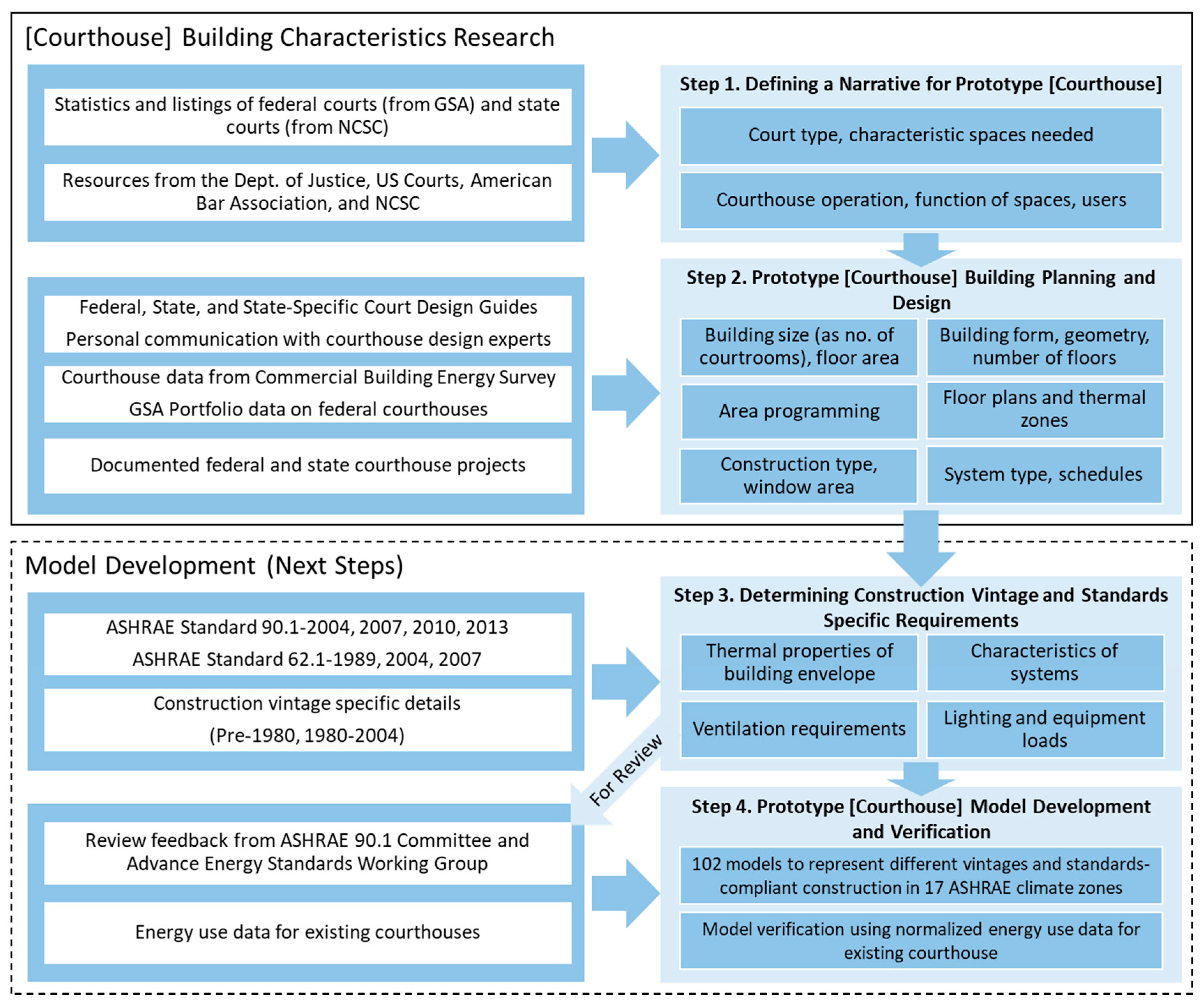
2. Methodology
2.1. Step 1: Defining a Narrative for Prototype Building
2.2. Step 2: Prototype Building Planning and Design
2.3. Step 3: Determining Construction Vintage and Standards-Specific Requirements
2.4. Step 4: Prototype Model Development and Verification
3. Prototype–Specific Building Characterization
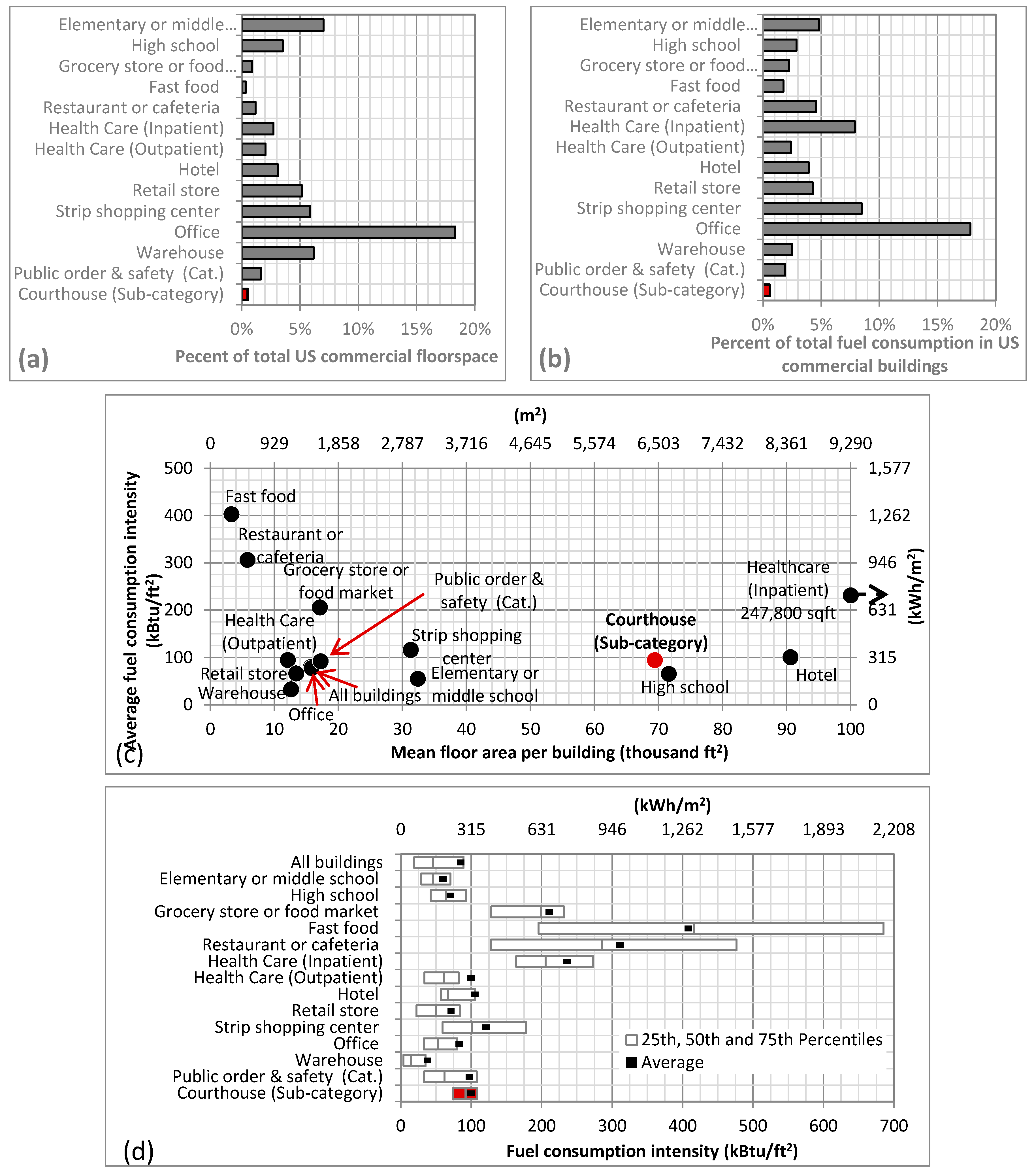
3.1. Common Statistics for Prototype Comparison
3.2. Operational Context
3.3. Prototype Building Design Principles
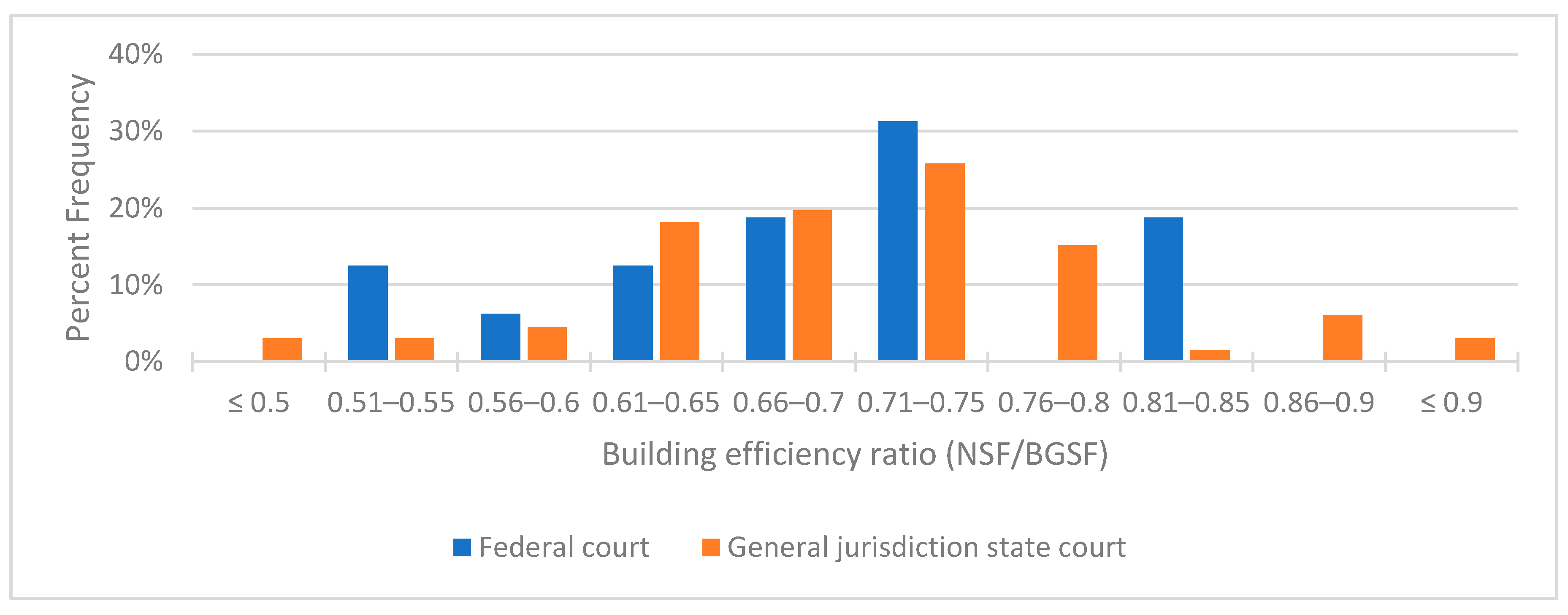
3.3.1. Grossing and Efficiency Factors
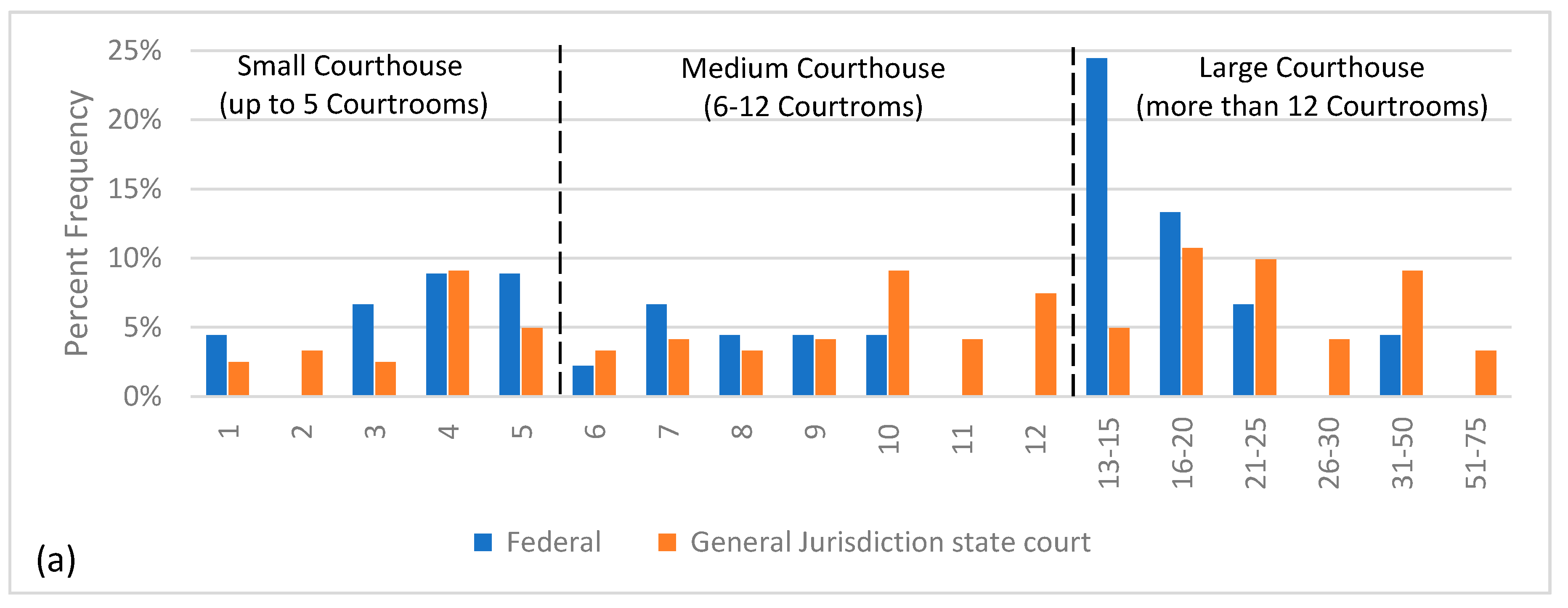
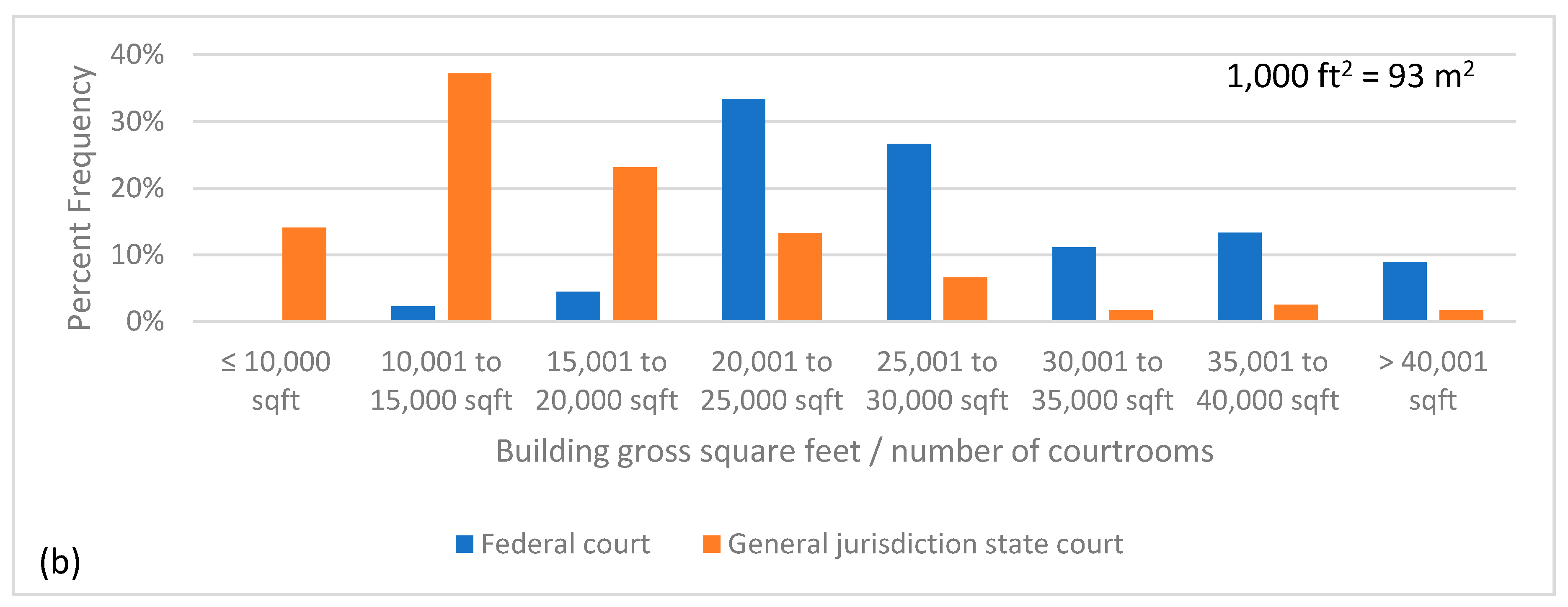
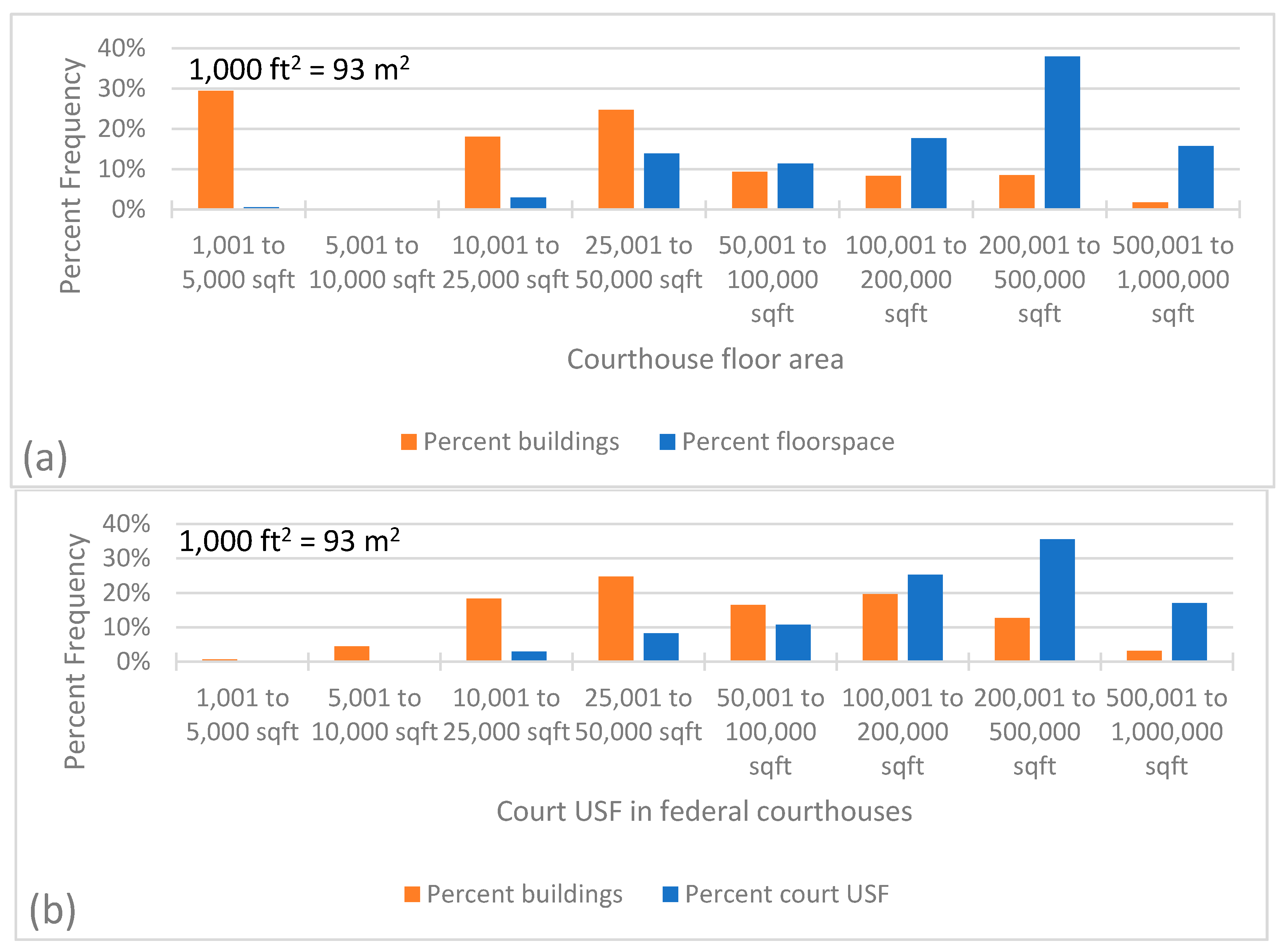
3.3.2. Scale and Size of Building
3.3.3. Characteristic Spaces
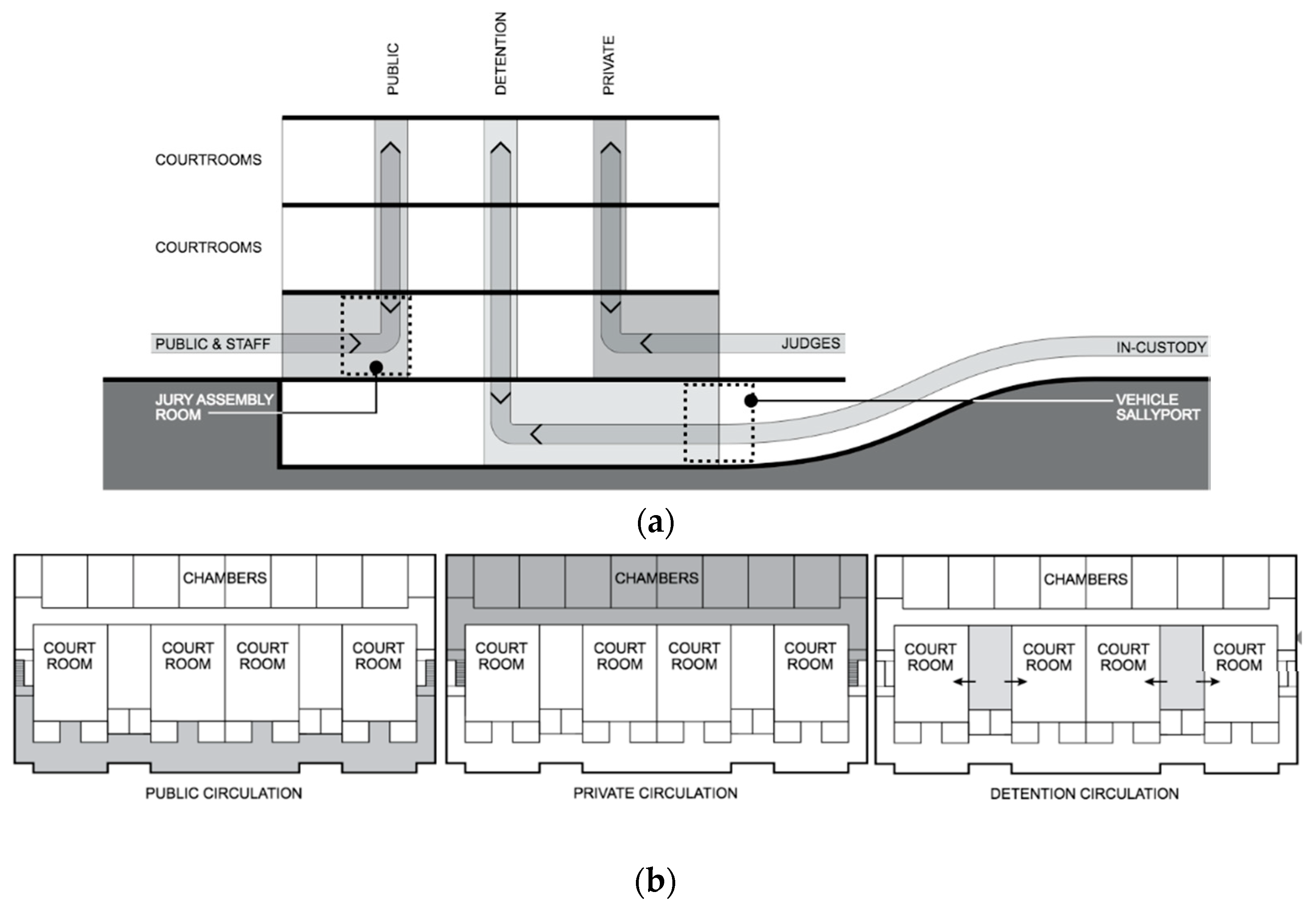
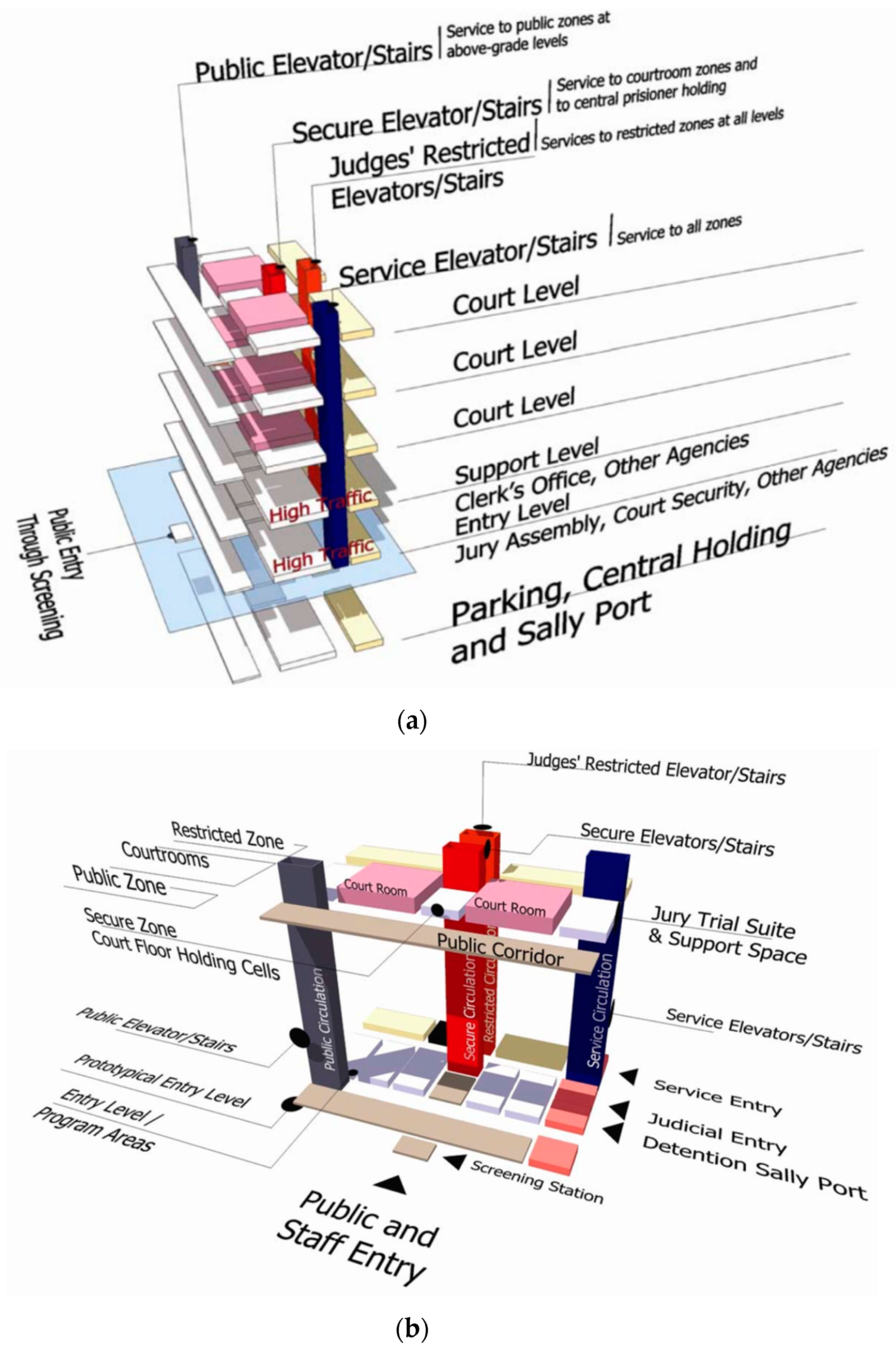
3.3.4. Circulation
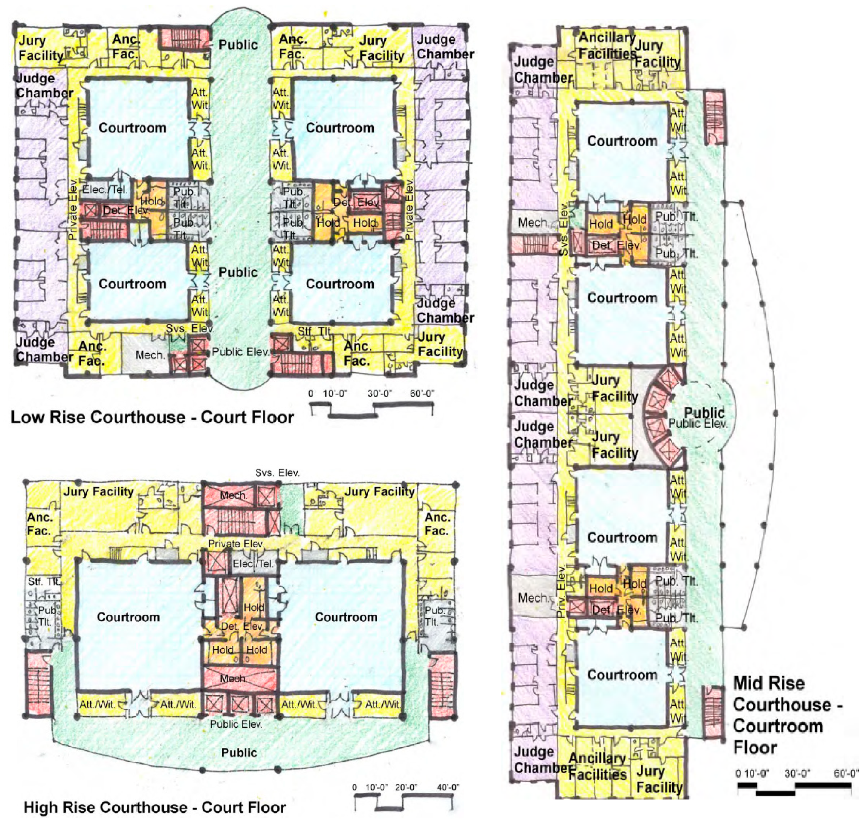
3.3.5. Adjacency, Stacking and Blocking
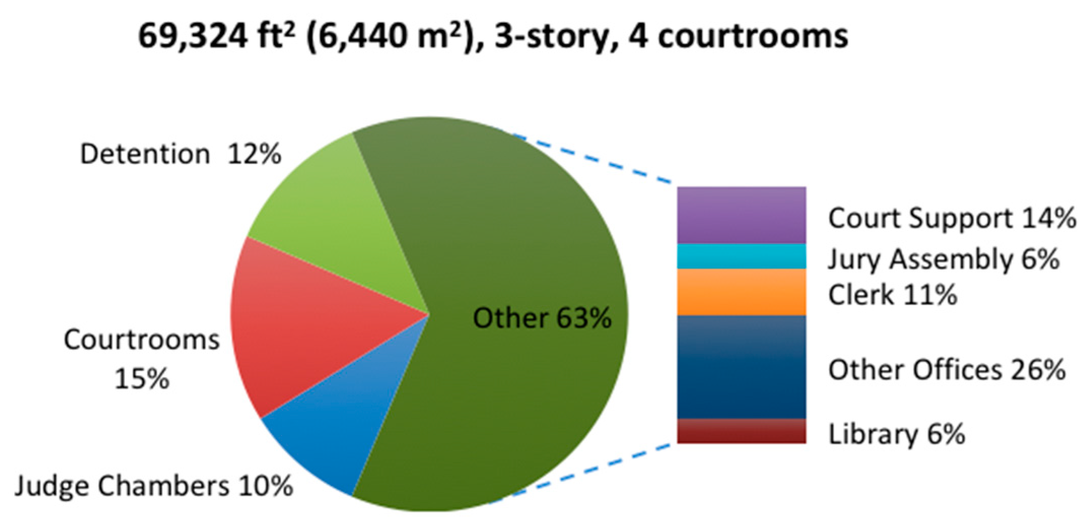
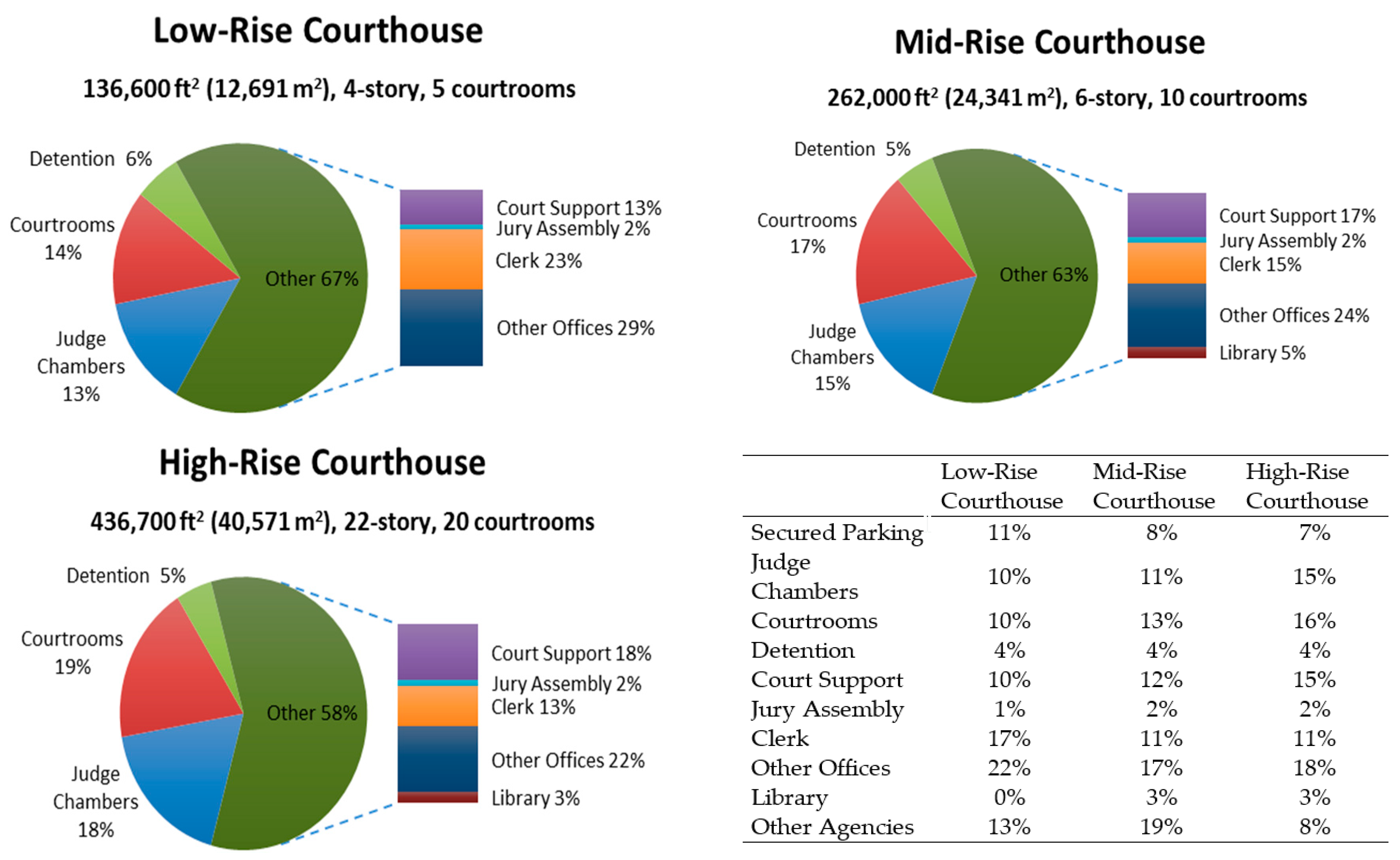
3.3.6. Space area Distribution
3.3.7. Space Standards and Heights
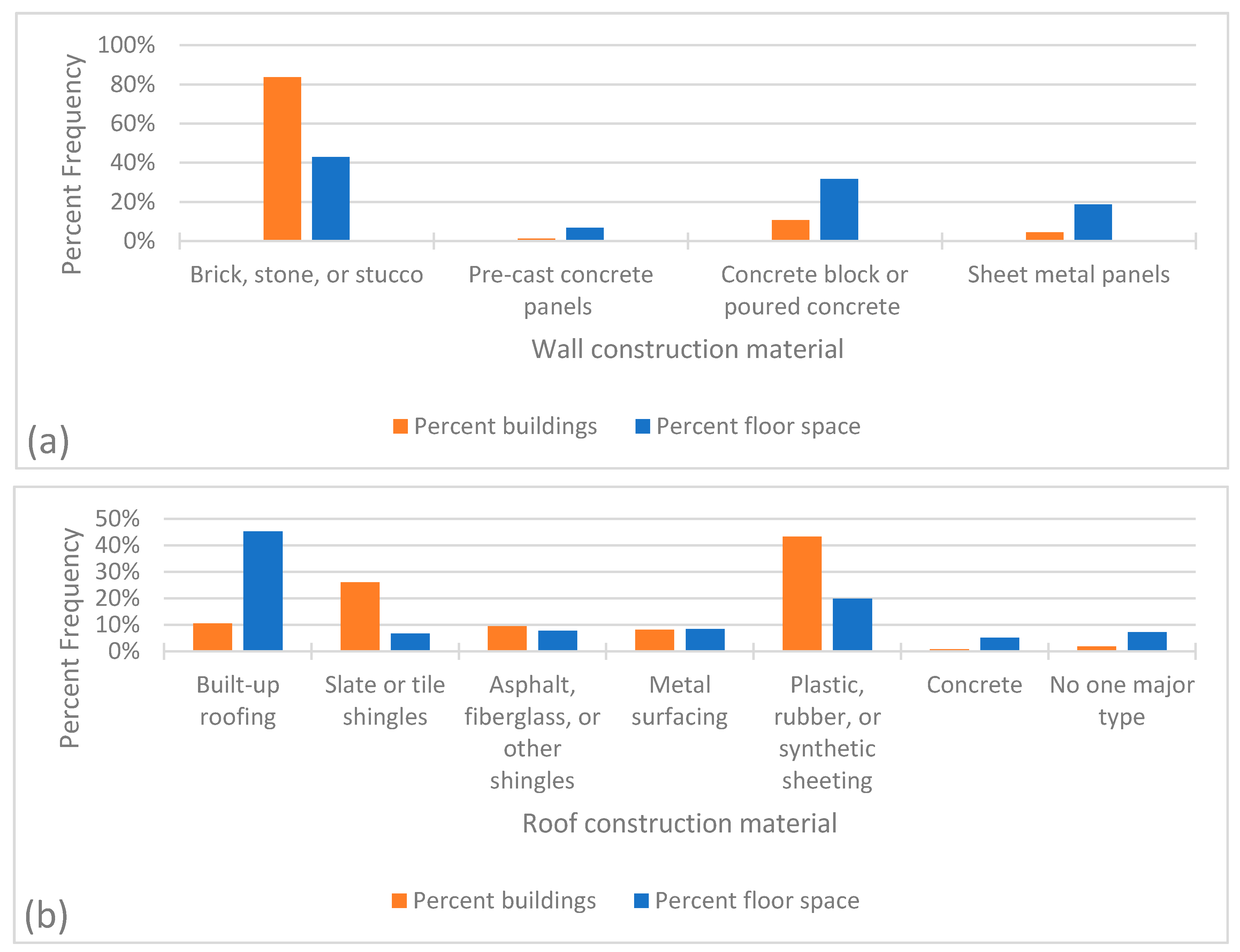
3.3.8. Construction
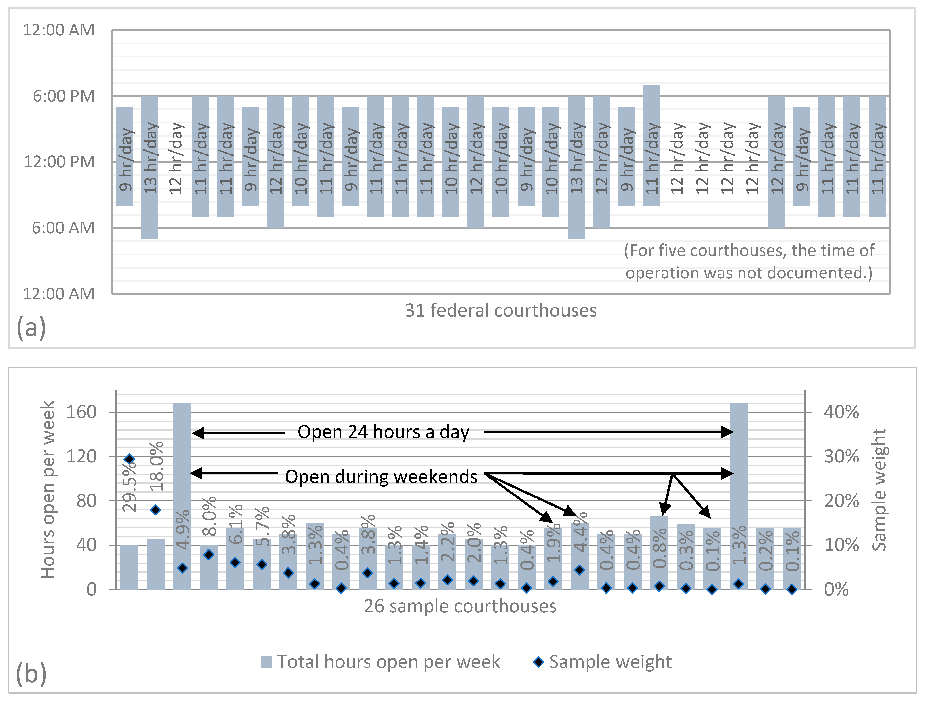
3.3.9. Schedule of Building Use
3.3.10. Control of HVAC System
3.4. Additional Findings from Prototype-Specific Datasets
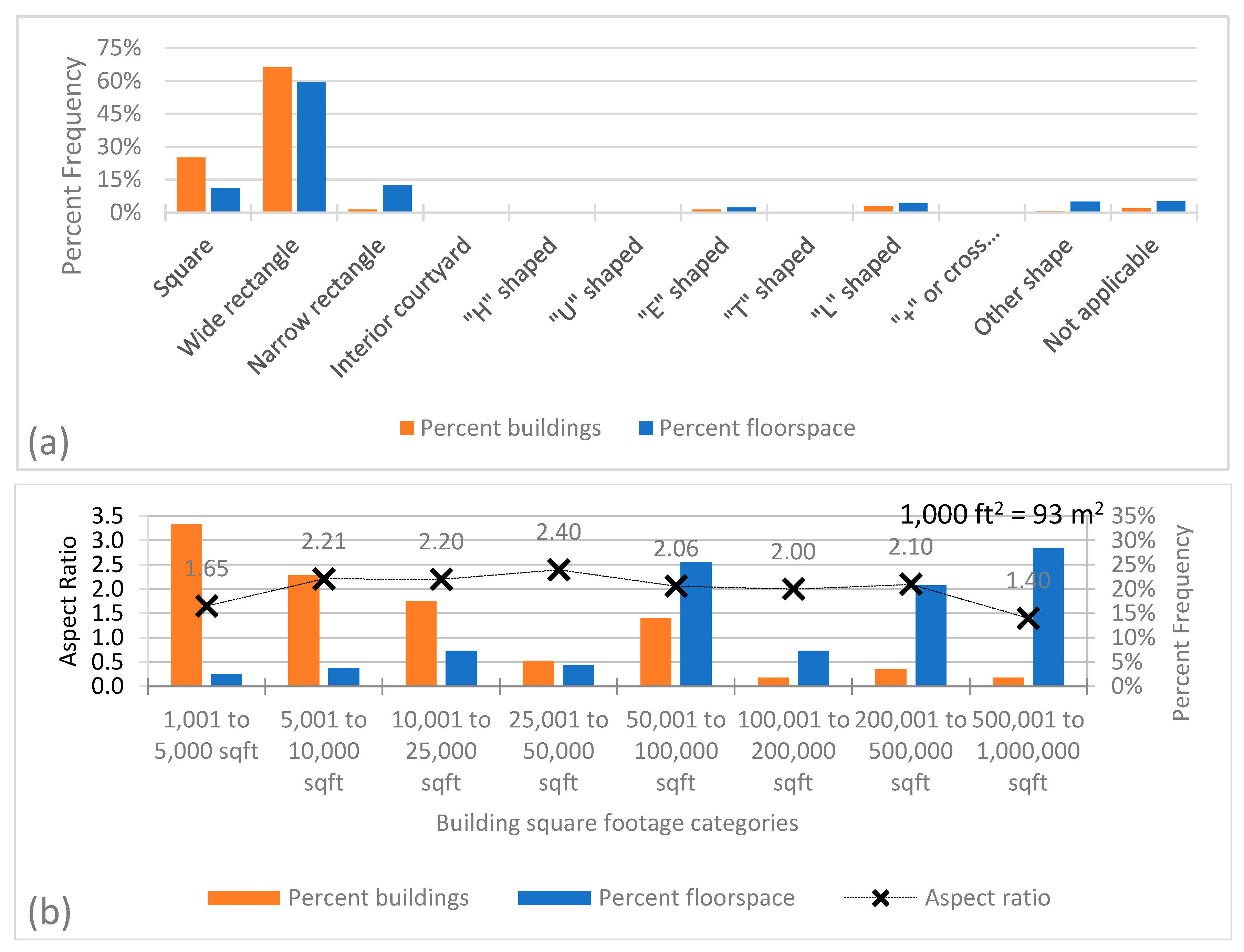
3.4.1. Building Area
3.4.2. Building Shape
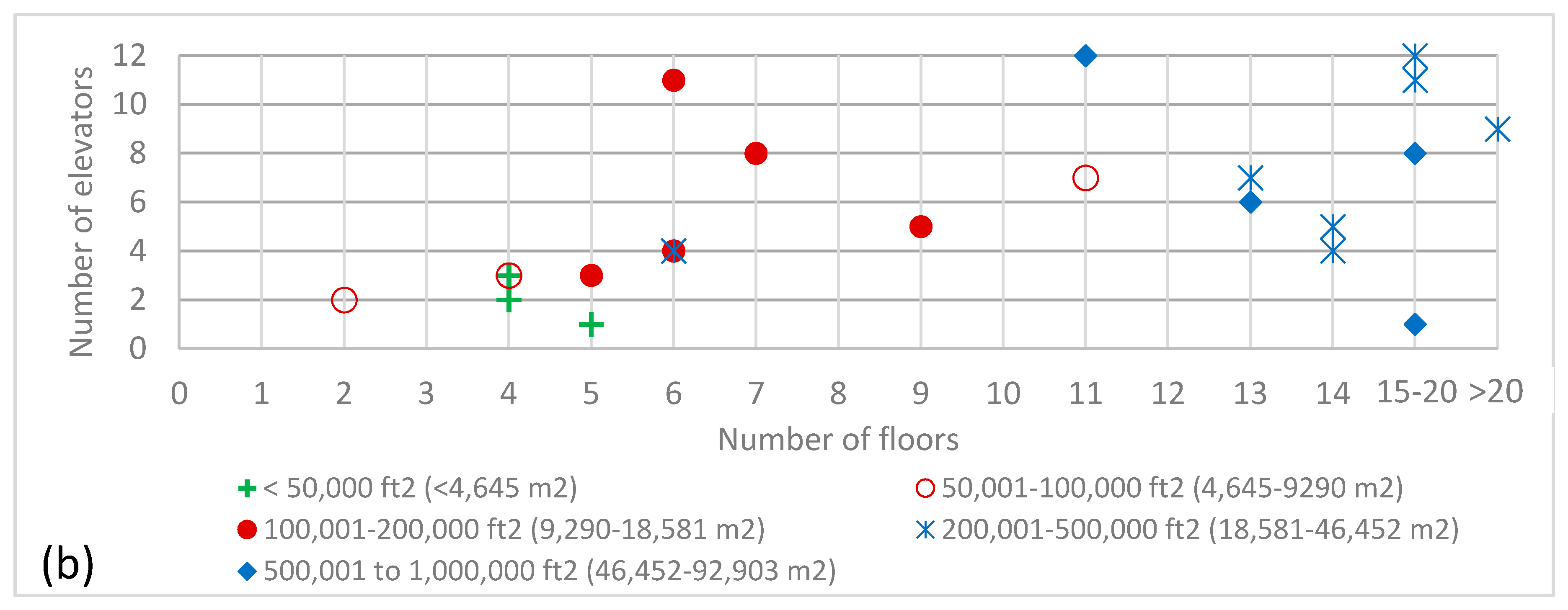
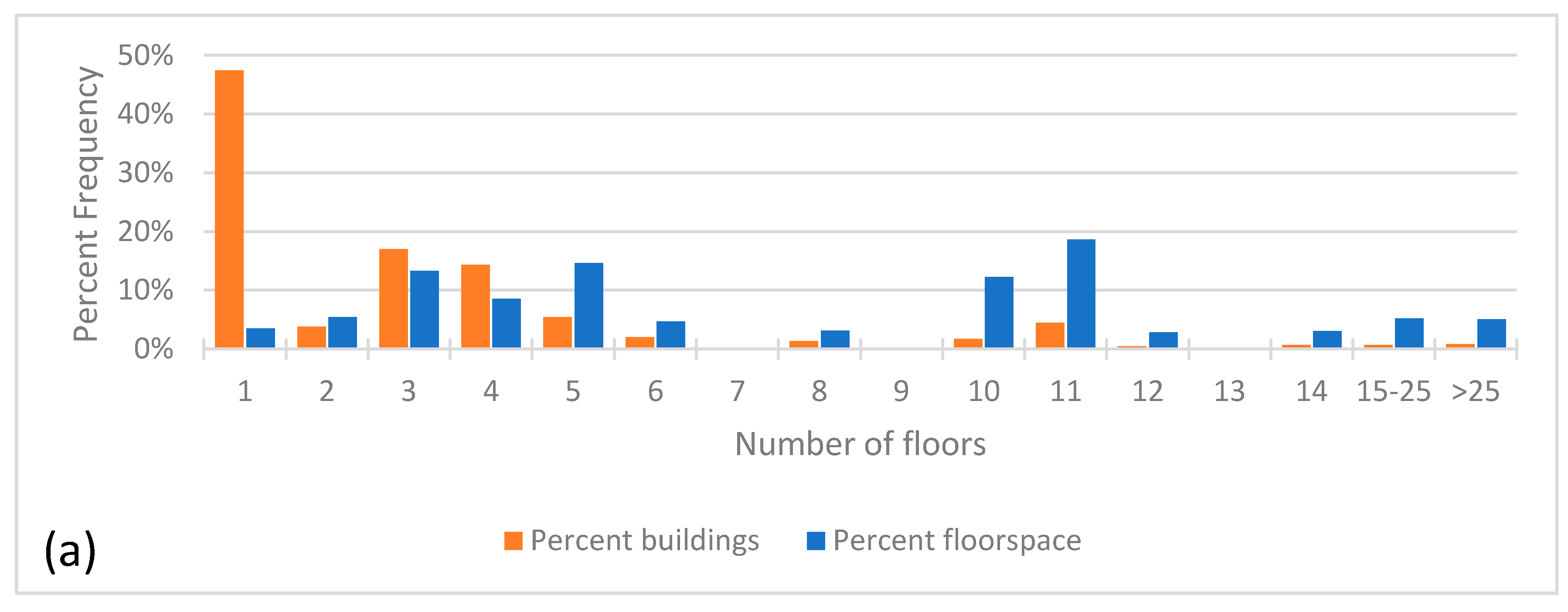
3.4.3. Number of Floors
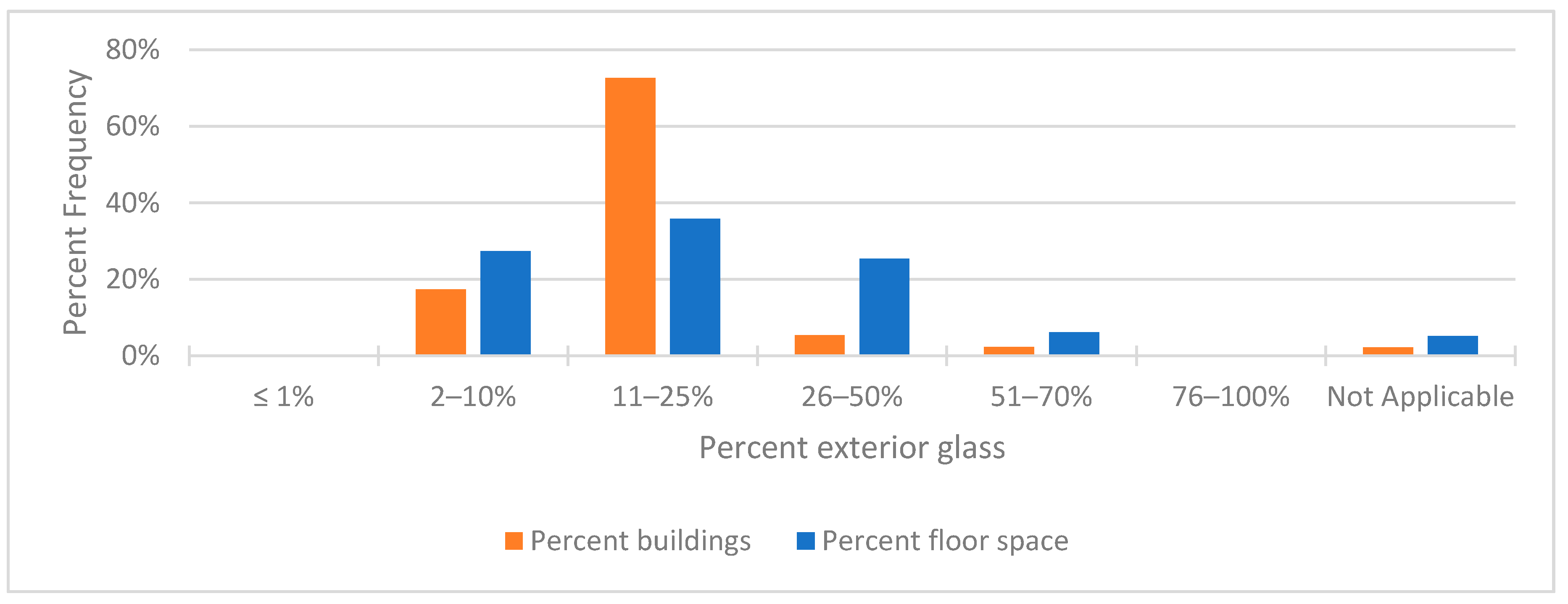
3.4.4. Windows
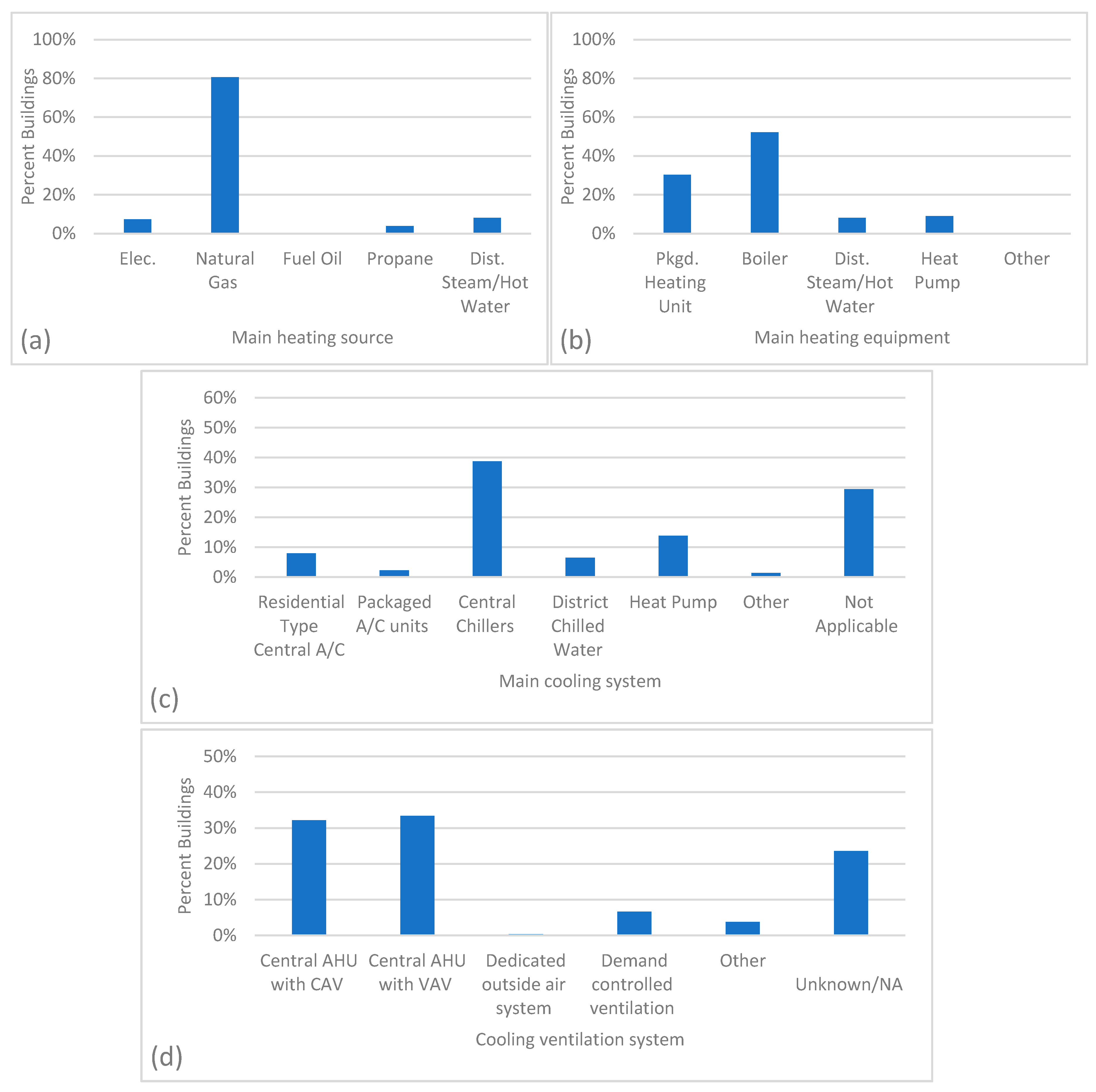
3.4.5. HVAC System
4. Prototype Decisions
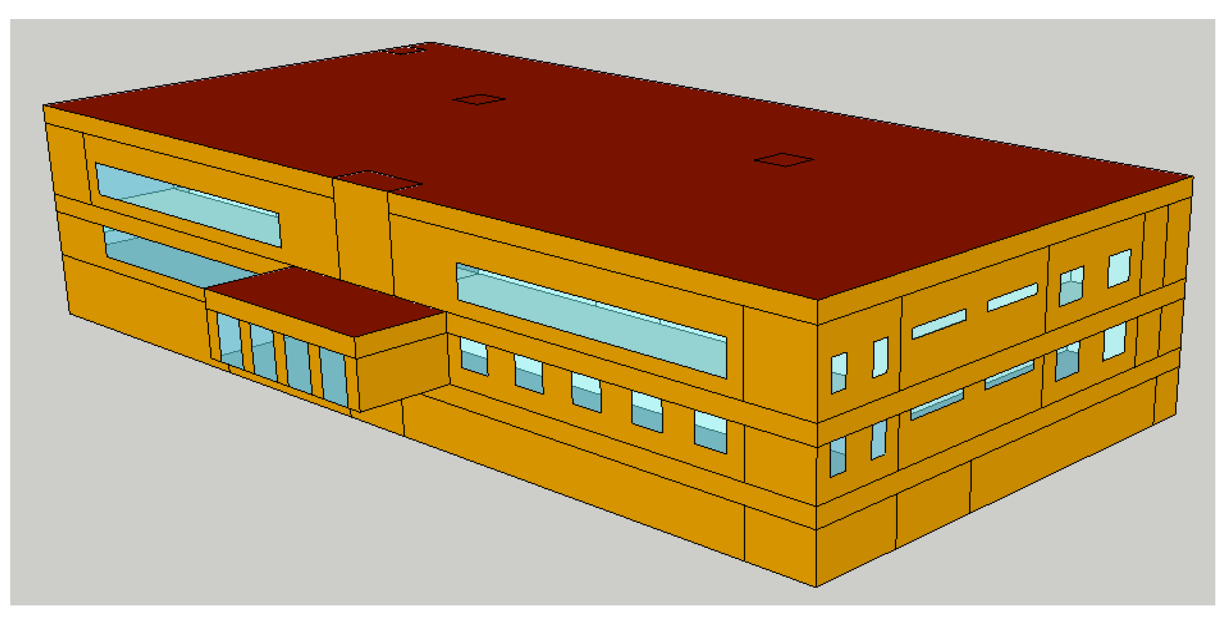
4.1. Building Geometry
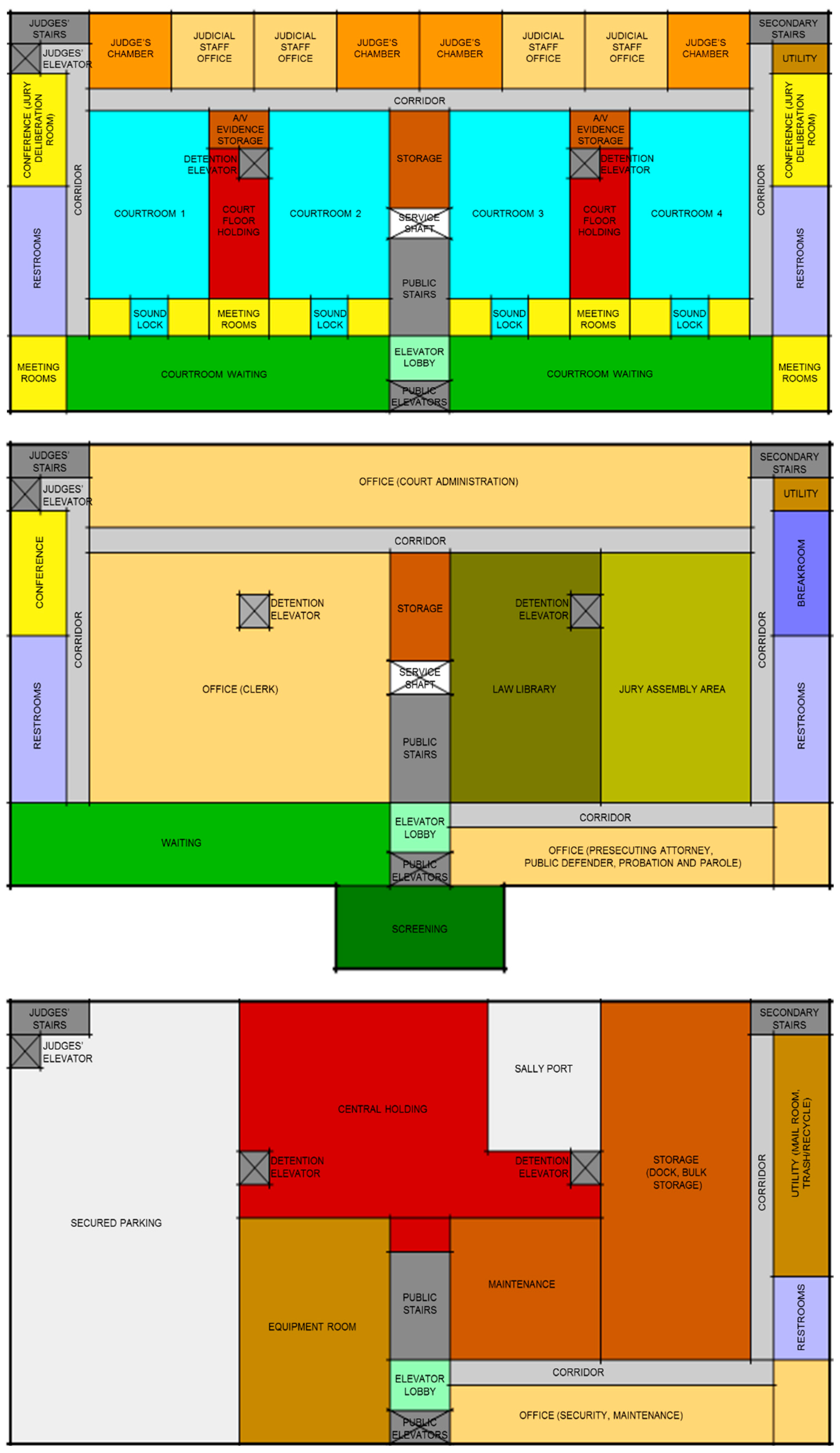
4.2. Floor Layout
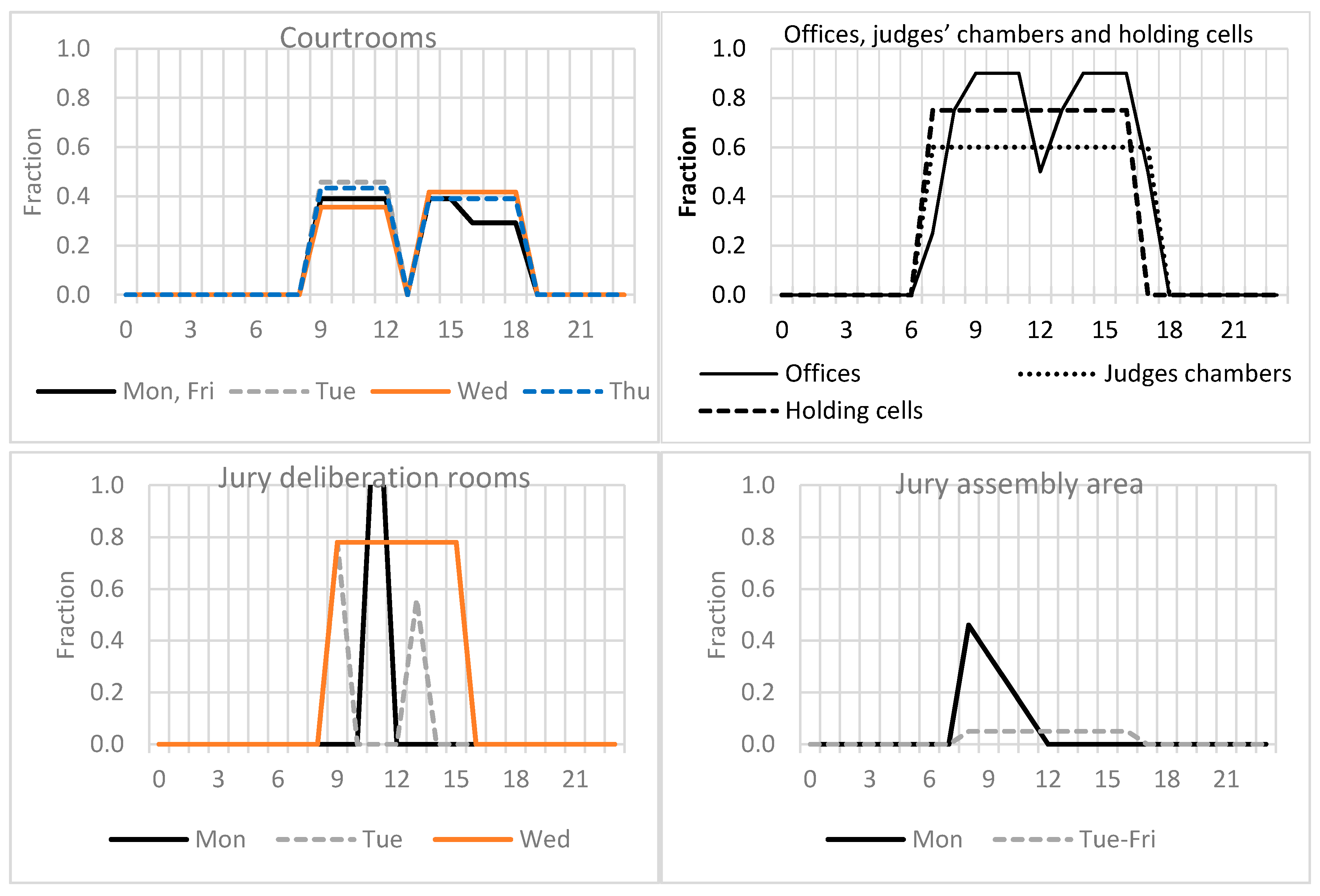
4.3. Occupancy Schedule
4.4. Windows
4.5. Construction
4.6. Systems and Equipment
5. Summary
- (1)
- Defining a narrative for the prototype building using databases and/or inventory of buildings and inputs from facility design experts who could advice on common building typologies, primary and secondary function in the building, space types, occupancy characteristics;
- (2)
- Prototype building planning and design using building design guides, case studies and inputs from facility design experts to determine the building size, form and geometry, area programming, floor plans and thermal zoning, construction type and windows, system type and schedule of use of spaces;
- (3)
- Determining detailed modeling specifications based on the requirements in building codes and standards (including thermal properties of the building envelope and characteristics of the heating, ventilation and air conditioning (HVAC) system, water heating system, lighting and equipment), followed by a review by building energy codes and standards experts;
- (4)
- Prototype model development according to the established protocols and model verification by comparing simulated energy use with available measured energy use and utility data from existing building datasets.
Author Contributions
Funding
Acknowledgments
Conflicts of Interest
References
- Building Technologies Office Multi-Year Program Plan, Fiscal Years 2016–2020; US Department of Energy: Washington, DC, USA, 2016.
- Deru, M.; Field, K.; Studer, D.; Benne, K.; Griffith, B.; Torcellini, P.; Liu, B.; Halverson, M.; Winiarski, D.; Rosenberg, M.; et al. U.S. Department of Energy Commercial Reference Building Models of the National Building Stock; NREL/TP-5500-46861; National Renewable Energy Laboratory: Golden, CO, USA, 2011. [Google Scholar]
- Commercial Reference Buildings. Energy.gov. n.d. Available online: https://www.energy.gov/eere/buildings/commercial-reference-buildings (accessed on 28 September 2019).
- Commercial Prototype Building Models. 2018. Available online: https://www.energycodes.gov/development/commercial/prototype_models (accessed on 28 September 2019).
- Climatic Data for Building Design Standards: ASHRAE Standard 169-2013; ASHRAE: Atlanta, GA, USA, 2013.
- Crawley, D.B. Building Simulation for Policy Support. In Building Performance Simulation for Design and Operation; Spon Press: New York, NY, USA, 2011; pp. 469–480. [Google Scholar]
- Advanced Energy Design Guides. Energy.gov. n.d. Available online: https://www.energy.gov/eere/buildings/advanced-energy-design-guides (accessed on 28 September 2019).
- Thornton, B.A.; Rosenberg, M.I.; Richman, E.E.; Wang, W.; Xie, Y.; Zhang, J.; Cho, H.; Mendon, V.V.; Athalye, R.A.; Liu, B. Achieving the 30% Goal: Energy and Cost Savings Analysis of ASHRAE Standard 90.1-2010; PNNL-20405; Pacific Northwest National Laboratory: Richland, WA, USA, May 2011. [Google Scholar]
- Wang, N.; Goel, S.; Srivastava, V.; Makhmalbaf, A. Building Energy Asset Score, Program Overview and Technical Protocol (Version 1.2); PNNL-22045 Rev. 1.2; Pacific Northwest National Laboratory: Richland, WA, USA, 2015. [Google Scholar]
- Karpman, M.; Wang, N.; Eley, C.; Goel, S. Comparative Analysis of ASHRAE Building EQ As-Designed, DOE Building Energy Asset Score and ASHRAE 90.1 Performance Rating Method Asset Ratings. In Proceedings of the Building Simulation 2017, San Francisco, CA, USA, 7–9 August 2017. [Google Scholar]
- Roth, A.; Brackney, L.; Parker, A.; Beitel, A. OpenStudio: A Platform for Ex Ante Incentive Programs. In Proceedings of the 2016 ACEEE Summer Study on Energy Efficiency in Buildings, Pacific Grove, CA, USA, 21–26 August 2016; Volume 4, pp. 1–12. [Google Scholar]
- Scout. Energy.gov. n.d. Available online: https://www.energy.gov/eere/buildings/scout (accessed on 28 September 2019).
- Roth, A. New OpenStudio-Standards Gem Delivers One Two Punch. Available online: https://www.energy.gov/eere/buildings/articles/new-openstudio-standards-gem-delivers-one-two-punch (accessed on 28 September 2019).
- Roth, A. Building Energy Modeling 101: Stock-Level Analysis Use Case. Available online: https://www.energy.gov/eere/buildings/articles/building-energy-modeling-101-stock-level-analysis-use-case (accessed on 28 September 2019).
- Lee, S.H.; Hong, T.; Sawaya, G.; Chen, Y.; Piette, M.A. DEEP: A Database of Energy Efficiency Performance to Accelerate Energy Retrofitting of Commercial Buildings; LBNL-180309; Lawrence Berkeley National Laboratory: Berkeley, CA, USA, 2015. [Google Scholar]
- Wang, N.; Makhmalbaf, A.; Srivastava, V.; Hathaway, J.E. Simulation-Based Coefficients for Adjusting Climate Impact on Energy Consumption of Commercial Buildings. Build. Simul. 2017, 10, 309–322. [Google Scholar] [CrossRef]
- Ng, L.C.; Quiles, N.O.; Dols, W.S.; Emmerich, S.J. Weather Correlations to Calculate Infiltration Rates for U. S. Commercial Building Energy Models. Build. Environ. 2018, 127, 47–57. [Google Scholar] [CrossRef] [PubMed]
- Shrestha, S.; Hun, D.; Ng, L.; Desjarlais, A.; Emmerich, S.; Dalgliesh, L. Online Airtightness Savings Calculator for Commercial Buildings in the US, Canada and China. In Proceedings of the Thermal Performance of the Exterior Envelopes of Whole Buildings XIII International Conference, Clearwater Beach, FL, USA, 4–8 December 2016; pp. 152–160. [Google Scholar]
- Building Activity Subcategory Tables from the 2012 CBECS Now Available [CBECS Status Update]. Available online: https://www.eia.gov/consumption/commercial/ (accessed on 28 September 2019).
- Irwin, R.; Chan, J.; Frisque, A. Energy Performance for ASHRAE 90.1 Baselines for a Variety of Canadian Climates and Building Types. In Proceedings of the eSim Conference, Hamilton, ON, Canada, 3–6 May 2016. [Google Scholar]
- Levine, M.; Feng, W.; Ke, J.; Hong, T.; Zhou, N. A Retrofit Tool for Improving Energy Efficiency of Commercial Buildings. In Proceedings of the 2012 ACEEE Summer Study on Energy Efficiency in Buildings, Pacific Grove, CA, USA, 12–17 August 2012; Volume 3, pp. 213–224. [Google Scholar]
- State Court Structure Charts. 2018. Available online: http://www.courtstatistics.org/Other-Pages/State_Court_Structure_Charts.aspx (accessed on 28 September 2019).
- National Center for State Courts. The Virtual Courthouse: A Guide to Planning and Design. n.d. Available online: http://courthouseplanning.ncsc.wikispaces.net (accessed on 1 July 2017).
- U.S. Courts Design Guide; Judicial Conference of the United States: Washington, DC, USA; Administrative Office of the U.S. Courts, Space and Facilities Division: Washington, DC, USA, 2007.
- California Trial Court Facilities Standards (Draft); Judicial Council of California, Administrative Office of the Courts: San Francisco, CA, USA, 2011.
- Minimum Courtroom Standards in the State of Illinois; Supreme Court of Illinois: Springfield, IL, USA, 2011.
- Project Development Guide Section III, Kentucky Court Facilities: Design and Construction. In Kentucky Court Facilities Design Guide; Kentucky Administrative Office of the Courts: Frankfort, KY, USA, 2007.
- The Michigan Courthouse: A Planning and Design Guide for Trial Court Facilities; Michigan Court Facilities Standards Project Advisory Committee: Lansing, MI, USA, 2000.
- Nebraska Courts Facility Planning: Guidelines and Standards; Supreme Court of Nebraska: Lincoln, NE, USA, 1999.
- PART 34 of Administrative Rules of the Unified Court System & Uniform Rules of the Trial Courts. In Guidelines for New York State Court Facilities; New York State Unified Court System: Albany, NY, USA, 2009.
- Utah Judicial Facility Design Standards; State of Utah Judicial Branch: Salt Lake City, UT, USA, 2016.
- Hardenbergh, D. Virginia Courthouse Facility Guidelines; Office of the Executive Secretary, Supreme Court of Virginia: Richmond, VA, USA, 2015. [Google Scholar]
- Construction Criteria for Space Type: Courtroom. In GSA Unit Cost Study; General Services Administration: Washington, DC, USA; pp. 20.1–20.9.
- Shell and Core: Courthouse. In GSA Unit Cost Study; General Services Administration: Washington, DC, USA; pp. C1–C35.
- Appendix I: DOE-2 Energy Modeling Summary—Courthouse. In GSA LEED Cost—Final Report; General Services Administration: Washington, DC, USA, 2004.
- Hardenbergh, D. Retrospective of Courthouse Design 1980–1991; National Center for State Courts: Williamsburg, VA, USA, 1992. [Google Scholar]
- Hardenbergh, D.; Phillips, T. Retrospective of Courthouse Design, 1991–2001; National Center for State Courts: Williamsburg, VA, USA, 2001. [Google Scholar]
- Yeh, C.M.; Hardenbergh, D.; Phillips, T. Retrospective of Courthouse Design 2001–2010; National Center for State Courts: Williamsburg, VA, USA, 2010. [Google Scholar]
- The Portfolio Data on Courthouses [Dataset]; Obtained with permission from the US Department of Judiciary; General Services Administration: Washington, DC, USA, 2017.
- Energy Savings Performance Contracts (ESPC) Investment Grade Audit Documentation of Federal Courthouses; Business Sensitive Reports; Not Available, Publicly; Federal Energy Management Program, Department of Energy: Washington, DC, USA, 2010.
- 2012 CBECS Public Use Microdata File [Dataset]. 2015. Available online: https://www.eia.gov/consumption/commercial/data/2012/index.php?view=microdata (accessed on 28 September 2019).
- OpenStudio Standards [Online Repository]; National Renewable Energy Laboratory: Lakewood, CO, USA.
- Atkinson, J. How the Legal System Works. In ABA Guide to Family Law; The American Bar Association: Chicago, IL, USA, 2014. [Google Scholar]
- Strickland, S.; Schauffler, R.; LaFountain, R.; Holt, K. Interactive State Court Organization App [Computer Application]; National Center for State Courts: Williamsburg, VA, USA, 2017. [Google Scholar]
- Dahabreh, S.M. The Formulation of Design: The Case of the Islip Courthouse by Richard Meier. 2006. Chapter 3. Available online: https://smartech.gatech.edu/handle/1853/10543?show=full (accessed on 21 October 2019).
- Design Standards for U.S. Court Facilities. In Facilities Standards for the Public Buildings Service, PBS-P100; U.S. General Services Administration: Washington, DC, USA, 2018; pp. 225–245.
- Justice Facilities—Courthouses. In ASHRAE Handbook—HVAC Applications; ASHRAE: Atlanta, GA, USA, 2015; pp. 9.5–9.6.
- 1992 CBECS Public Use Microdata [Dataset]. 1996. Available online: https://www.eia.gov/consumption/commercial/data/1992/index.php?view=microdata (accessed on 28 September 2019).


| Categories | Low-Rise | Mid-Rise | High-Rise | |||
|---|---|---|---|---|---|---|
| Building Description | ||||||
| Number of floors below grade | 1 | 1 | 2 | |||
| Number of floors above grade | 3 | 5 | 20 | |||
| Penthouse | 1 | – | 1 | |||
| Footprint area | 38,584 ft2 | (3585 m2) | 43,296 ft2 | (4022 m2) | 24,000 ft2 | (2230 m2) |
| Building gross square feet (BGSF) | 136,600 ft2 | (12,691 m2) | 262,000 ft2 | (24,341 m2) | 436,700 ft2 | (40,571 m2) |
| Characteristic Spaces | ||||||
| Number of courtrooms 1 | 3 trial + 1 bankruptcy | 8 trial + 2 bankruptcy | 16 trial + 4 bankruptcy | |||
| Number of judges’ chambers | 4 | 10 | 20+ 2 | |||
| Number of jury deliberation rooms | 3 | 8 | 16 | |||
| Usable Square Feet (USF) | ||||||
| Court | 73,793 ft2 | (6856 m2) | 138,831 ft2 | (12,898 m2) | 251,137 ft2 | (23,331 m2) |
| Other agencies | 12,826 ft2 | (1192 m2) | 35,199 ft2 | (3270 m2) | 25,169 ft2 | (2338 m2) |
| Subtotal | 86,620 ft2 | (8047 m2) | 174,030 ft2 | (16,168 m2) | 276,306 ft2 | (25,670 m2) |
| Secured covered parking | 11,000 ft2 | (1,022 m2) | 15,000 ft2 | (1394 m2) | 20,000 ft2 | (1858 m2) |
| Total | 97,620 ft2 | (9069 m2) | 189,030 ft2 | (17,561 m2) | 296,306 ft2 | (27,528 m2) |
| Area Programming Metrics | ||||||
| USF of court and other agencies /BGSF | 63.4% | 66.4% | 63.3% | |||
| Court USF/number of courtrooms | 14,759 ft2 | (1371 m2) | 13,883 ft2 | (1290 m2) | 12,557 ft2 | (1167 m2) |
| BGSF/number of courtrooms | 27,320 ft2 | (2538 m2) | 26,200 ft2 | (2434 m2) | 21,835 ft2 | (2029 m2) |
| Category | Description |
|---|---|
| Form | |
| Total floor area | 69,324 ft2 (6440 m2) |
| Building footprint | 218 ft × 106 ft (66.4 m × 32.2 m); 2.06:1 aspect ratio; non-directional azimuth |
| Number of floors | 3 (including partly conditioned basement) |
| Floor-to-ceiling height | 10 ft (3.3 m) for basement and first floor; 16 ft (4.9 m) for second floor; 4 ft (1.2 m) ceiling plenum |
| Volume of building | 1,121,179 ft3 (31,748 m3) |
| Window-to-wall ratio | 18.4% (front: 24.3%, right: 10.1%, back: 13.6%, left: 12%) |
| Window height | 6 ft (1.8 m); 4 ft (1.2 m) sill height |
| Construction a | |
| Exterior walls | Concrete masonry unit, stucco on the exterior, interior wall insulation |
| Roof | Built-up roof on metal decking and roof insulation |
| Fenestration system | Punched window system with hypothetical windows defined by U-factor and SHGC (i.e., glass type and window frame not explicitly defined); no exterior shading; no skylights |
| Foundation | Heavyweight concrete for basement walls and floor |
| Interior partitions | Steel-frame walls; concrete for vertical shafts and detention areas |
| Systems and equipment b | |
| HVAC system | Gas boiler, water-cooled chiller; variable air volume (VAV) terminal box with damper and hot water reheating coil |
| Service water heater | Storage type, natural gas water heater |
| Elevator | 5 hydraulic elevators including two public elevators, one judges’ elevator and two elevators for in-custody defendants |
© 2019 by the authors. Licensee MDPI, Basel, Switzerland. This article is an open access article distributed under the terms and conditions of the Creative Commons Attribution (CC BY) license (http://creativecommons.org/licenses/by/4.0/).
Share and Cite
Malhotra, M.; Im, P.; New, J. A Process for Defining Prototype Building Models: Courthouse Case Study for U.S. Commercial Energy. Energies 2019, 12, 4020. https://doi.org/10.3390/en12204020
Malhotra M, Im P, New J. A Process for Defining Prototype Building Models: Courthouse Case Study for U.S. Commercial Energy. Energies. 2019; 12(20):4020. https://doi.org/10.3390/en12204020
Chicago/Turabian StyleMalhotra, Mini, Piljae Im, and Joshua New. 2019. "A Process for Defining Prototype Building Models: Courthouse Case Study for U.S. Commercial Energy" Energies 12, no. 20: 4020. https://doi.org/10.3390/en12204020
APA StyleMalhotra, M., Im, P., & New, J. (2019). A Process for Defining Prototype Building Models: Courthouse Case Study for U.S. Commercial Energy. Energies, 12(20), 4020. https://doi.org/10.3390/en12204020