Article

Research on Double-Layer Optimized Configuration of Multi-Energy Storage in Regional Integrated Energy System with Connected Distributed Wind Power

1
State Grid Sichuan Economic Research Institute, Chengdu 610000, China
2
Tsinghua Sichuan Energy Internet Research Institute, Chengdu 610000, China
3
College of Electrical Engineering, Zhejiang University, Hangzhou 310027, China
*
Author to whom correspondence should be addressed.
Energies 2019, 12(20), 3964; https://doi.org/10.3390/en12203964
Submission received: 9 September 2019 / Revised: 7 October 2019 / Accepted: 15 October 2019 / Published: 18 October 2019
(This article belongs to the Section F: Electrical Engineering)

Abstract

:
With the wide application of multi-energy storage technology in the regional integrated energy system, the configuration of multi-energy storage devices is expected to enhance the economic benefits of regional integrated energy systems. To start with, in this paper, the basic framework of the regional integrated energy system is constructed, and a mathematical model of micro-gas turbine, gas boiler, distributed wind power and multi-energy storage device is established. Then, the multi-energy storage and double-layer planning configuration model with multi-energy complementation is established. The upper level of the model aims to minimize the comprehensive investment cost of multi-energy storage, while the lower level of the model aims to minimize the comprehensive systematic operating cost, in which the net losses cost is also included and the required multi-energy storage capacity from the upper level is set as its constraint. During the programming and problem solving, the second-order conic relaxation technology is introduced to realize the convex relaxation for power flow constraint. At the same time, the piecewise linearization method is adopted to deal with the natural gas pipeline flow constraint, which can convert the original model into a mixed integer programming problem. In the end, the example analysis is carried out in the IEEE 33-bus system and the improved 6-node natural gas system. The results show that the multi-energy storage technology can improve the economics of the regionally integrated energy system to a certain extent, and have verified the validity of the model.

1. Introduction

In recent years, the fossil energy crisis and environmental problems are becoming increasingly prominent, and the concept of energy interconnection has provided a new way of thinking for solving this problem [1]. As an important component of energy interconnection [2], the regionally integrated energy system focuses on the distributed energy production and in-place energy consumption aiming to achieve high energy consumption efficiency [3]. However, the penetration of distributed renewable energy has put forward new requirements for energy storage systems in terms of capacity, cost and storage time [4,5], while traditional electrical storage devices struggle to meet these requirements at the same time [6,7,8,9]. In this way, it is of practical significance to configure multi-energy storage devices in regional integrated energy systems.
Traditionally, different energy systems are planned and operated separately. Thus, the lack of coordination and linkage between them has led to a lack of renewable energy. As a conversion device between electricity and gas energy systems [10], the gas turbine unit uses the natural gas as the fuel to generate electricity and provides its users with heat by reusing the residual heat discharged through the waste heat recycling system; or provides its users with cooling by chiller conversion, thus to realize the step-up utilization of the regional energy system. A two-stage mixed-integer linear stochastic optimization model is proposed in paper [11] to analyze the scheduling of electricity-production units under natural gas-supply uncertainty due to pipeline congestion and natural gas-price variability. An integrated electricity and gas system with the lowest comprehensive cost for collaborative optimization is proposed in paper [12]. Artificial optimization algorithms to calculate and optimize the operation strategy of a regional integrated energy system based on economic benefits and energy consumption are implemented in paper [13]. However, no papers illustrated above have considered the energy storage device.
In the integrated energy system, the storage system has become the key equipment for the flexible energy conversion between various energy forms. It can solve the production and consumption asynchronization between various energies [14]. The comprehensive multi-energy storage scheduling method of the integrated energy system for wind power consumption in the Three-North Area of China is proposed in paper [15]. How the availability of micro-grids during natural disasters and in their aftermath can be assessed is discussed in paper [16]. The model considers two critical groups of components that allow micro-grids to improve power supply availability: distributed generators and local energy storage. A hybrid energy storage system built with a virtual energy storage system (VESS) and a battery system (BSS) is proposed in paper [17] in order to increase renewable energy penetration into integrated community energy systems (ICESs) and prevent power fluctuations of the tie-line (connection of the ICESs to the main grid). However, most models illustrated above are only related to the battery model and have almost no relationship with the multi-energy storage devices that heat storage devices included.
As the power flow constraint and natural gas pipeline flow constraint are all non-linear constraints, the artificial algorithm is implemented in papers [18,19,20,21]. However, artificial algorithms can hardly operate well in a local optimal solution. Thus, the newly developed methods in recent years like semidefinite relaxation (SDR), second-order conic relaxation (SOCR), and interior point method have provided new ideas for solving these problems. Second-order conic relaxation method is adopted in this paper to realize convex relaxation for the power flow constraint. The piecewise linearization method is adopted to deal with natural gas pipeline flow constraint by converting the original model into mixed-integer second-order conic scheduling problem, thus the numerical method can be applied to the fast and reliable solution.
Moreover, the planning and operation of energy storage are mutually reinforcing and inseparable. The double-layer decision model is now normally used in planning and configuration problems of energy storage, and the planning model can be divided into investment layer and operation layer [22,23,24].
In summary, the double-layer model of multi-energy storage configuration in the regional integrated power system that considers different wind power specific permeabilities is proposed. The main contents of this paper are concluded as follows:
In Section 2, a basic framework structure of the multi-energy storage system in the regional integrated power system is built, and the detail configuration and elements in the regional integrated power system are proposed.
In Section 3, the double-layer planning model that considers the multi-storage investment-operation is established, which includes the objective function and constraints of the upper layer and lower layer model.
In Section 4, the second-order conic relaxation and piecewise linearization are implemented in the proposed double-layer planning model.
In the last section of the paper, the correctness of the proposed model is verified under different experiments.

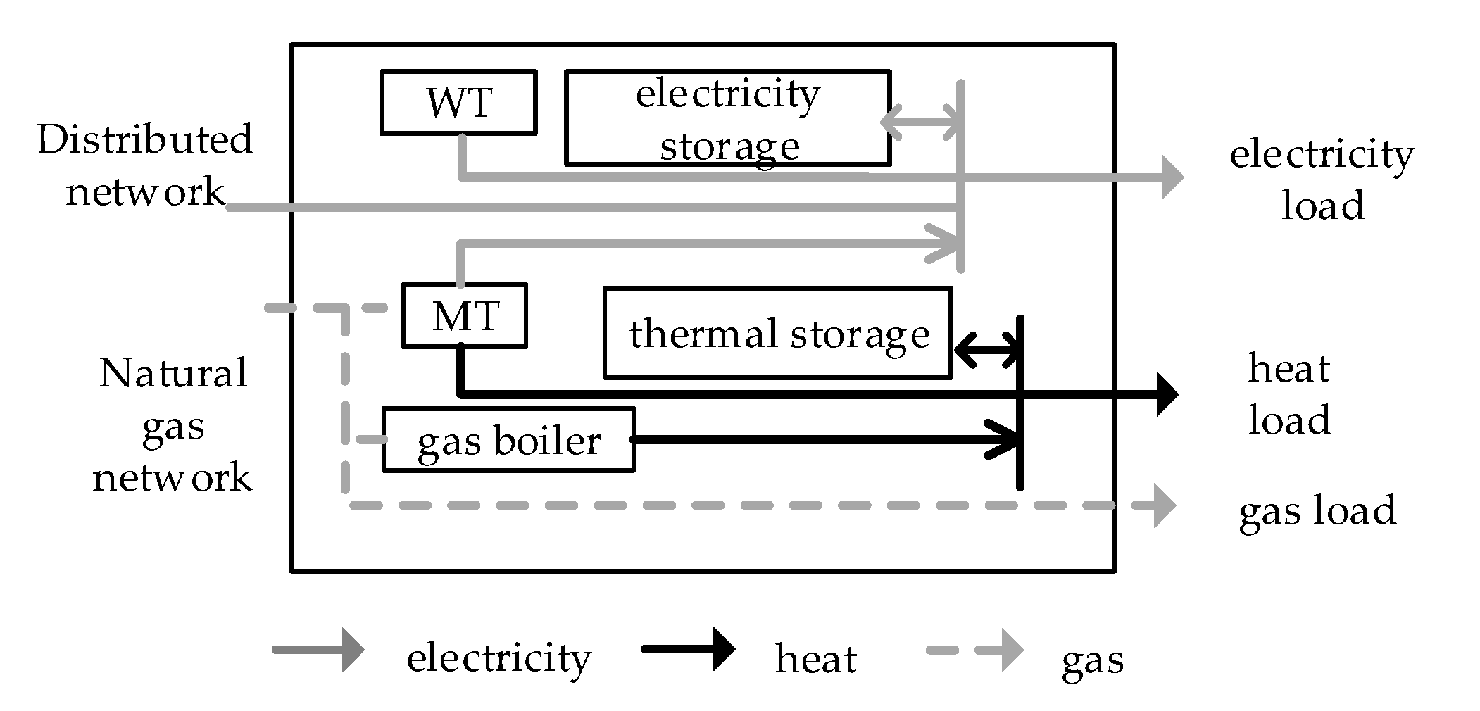
2. Framework of Regional Integrated Energy System

As the primary form of the global interconnection, the regional integrated energy system is an important foundation for the smart city and smart community. From the framework aspect, it can be regarded as an energy unit with multiple inputs, outputs, conversions and energies sharing high constructive and operational flexibility. Based on common forms of the regional energy system, this paper establishes the equipment which includes the micro-gas turbine (MT), gas boiler, distributed wind turbine (WT), electricity storage unit, and thermal storage unit, shown as in Figure 1.

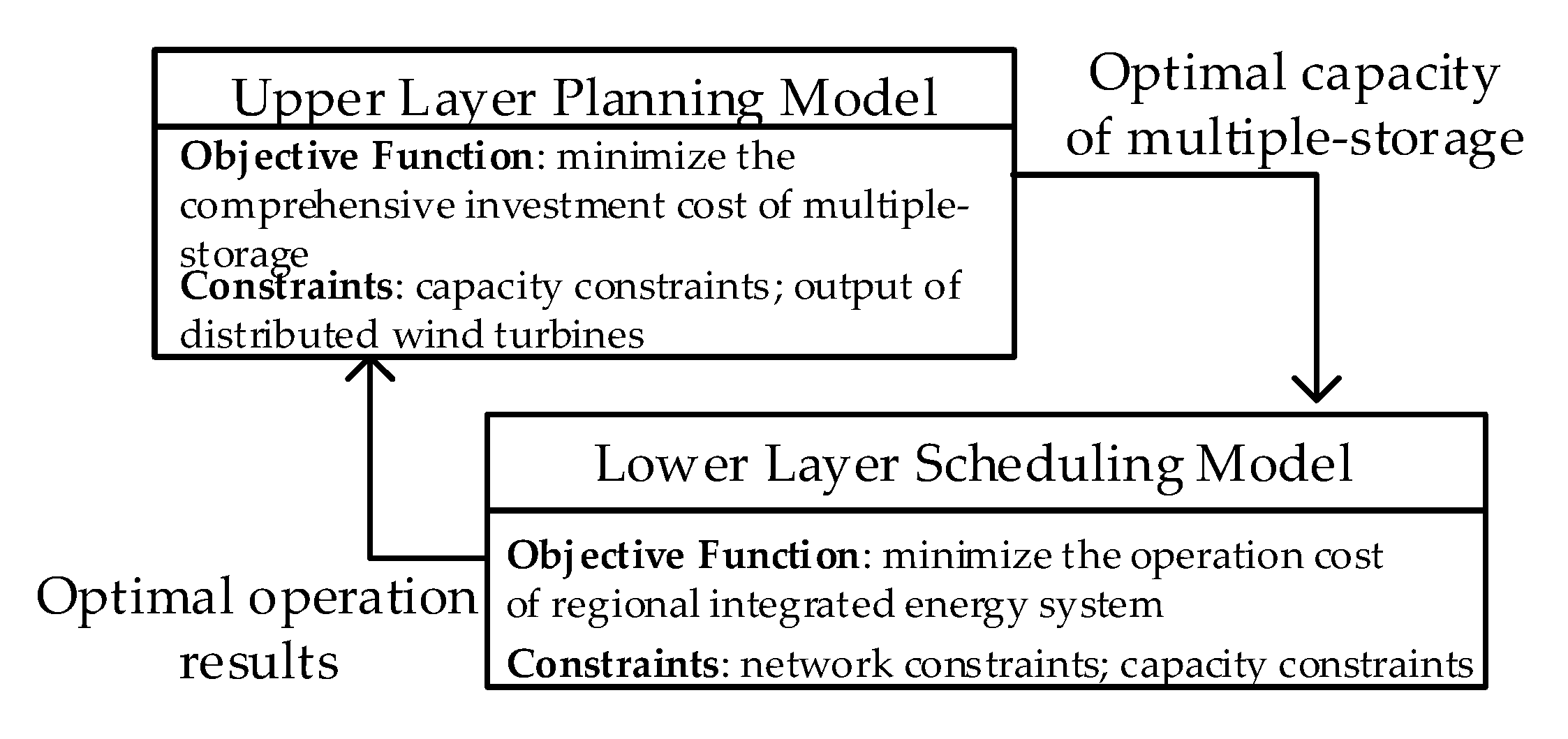
3. Double-Layer Optimized Model for Multi-Energy Storage

The multi-energy storage components in the regional integrated energy system are of great significance in the multi-energy complementarity and coordinated operation. Electricity storage devices can play the role of cutting peaks and filling the valley and improving the operation economy of the integrated system. However, as the micro-gas turbine in the thermal system is in accordance with the operation mode of “electricity is determined by thermal energy”, its peak scheduling ability is limited by the operating plan set by end-of-the-terminal energy. In this way, the implementation of the thermal storage device can play a role in improving the adjustability of the thermal system as a backup of regulated resources.
This paper establishes an optimized configuration of a double-layer model of multi-energy storage that considers the multi-energy complementation. The upper layer aims to minimize the comprehensive investment cost of the multi-energy storage and tries to find the optimal capacity configuration of various types of energy storage devices. The lower layer aims to minimize the comprehensive yearly operating cost in the regional integrated energy system by taking the multi-energy storage capacity from the upper layer as a constraint. Then, the optimal yearly operating cost will be transferred to the upper layer of the model. The difference between the upper and lower objective function is represented by the parameter ε , iteration stops when ε is less than the set value. By increasing iteration of the double-layer optimized model, the value of optimal capacity configuration of the multi-energy storage can be found. The framework of the bi-level optimization model is shown in Figure 2.

3.1. Upper Layer Planning Model Considering the Comprehensive Investment Cost of Multi-Storage

3.1.1. Objective Function of Upper Layer Model

In the planning layer of the regional integrated energy system when multi-energy storage is included, the operating maintenance cost and operating cost transmitted by operating layer of the lower layer should be considered. The safety of the integrated energy system should also be the prerequisite of planning. The target function can be written as:
min [ 365 t = 1 24 ( C i n s e , e l e + C m , e l e ) E P    + ( C i n s e , h + C m , h ) E H ] + n = 1 M C O C ( 1 ( 1 + r ) ) n

3.1.2. Constraints of Upper Layer Model

The constraints of the upper model mainly take the permeability constraint of distributed energy and the investment capacity constraint of the multi-energy storage device into account, which can be expressed as:
E P min ( t ) E P ( t ) E P max ( t )
E H min ( t ) E H ( t ) E H max ( t )
P wind , min ( t ) η wind P wind ( t ) P wind , max ( t ) η wind
The output of active power of the distributed wind turbines usually approximates the Weibull distribution, and its active power output can be expressed as [25]:
f [ P W T ( v ) ] = { 0 , 0 v v i   or   v i v o P r v v i v r v i , v i v v r P r , v r v v o
where v i , v r and v o are respectively the cut-in wind speed, rated wind speed and cut-out wind speed of distributed wind turbine; Pr is the rated output power of distributed wind turbines.
With advantages of high charging efficiency and high energy density, the lead-acid battery is implemented in electricity storage devices in the regional integrated energy system. At the same time, the model can be described as follows if assuming that the charge and discharge power of the electrical storage device is constant during a scheduling cycle and its charging capacity is ignored with the dissipation of the energy storage time:
{ I char ( t ) + I dis ( t ) 1 0 P dis ( t ) I dis ( t ) P max 0 P char ( t ) I char ( t ) P max E P min ( t ) E P ( t ) E P max ( t ) E P ( t + 1 ) = E P ( t ) + α c P char ( t ) α d P dis ( t )
where P dis ( t ) , P char ( t ) , E P ( t ) and P max are respectively discharge power, charging power, charging capacity and maximum charge and discharge power of electricity storage device at the time t, α d and α c are respectively the discharge and charge factors, and E P min and E P max are respectively the lower and upper charging capacity of the electricity storage device.
The thermal electric boiler is adopted in this research as the heat storage device, which can store the heat by converting electricity to heat power under high power conditions. To simplify the analysis, the modeling method in papers [26,27] was adopted in this paper. Assuming that the heat storage device will not dissipate energy over time, the remaining heat calculation formula can be expressed as:
E H ( t + 1 ) = E H ( t ) + β c h a r H c h a r ( t ) β d i s H d i s ( t )
where E H ( t + 1 ) and E H ( t ) are remaining heats of the heat storage devices at time t and t − 1 respectively. β d i s and β c h a r are respectively heat release and heat storage coefficient, H c h a r and H d i s are respectively heat storage and release power. Where the capacity and heat storage power of the thermal storage unit should meet the following requirements:
0 H c h a r ( t ) H max
0 H d i s ( t ) H max

3.2. Lower Layer Scheduling Model of Regional Integrated Energy System

3.2.1. Objective Function of Lower Layer Model

In the lower layer of the optimized scheduling model of the regional integrated energy system, as the comprehensive operating cost in the system is aimed to be minimized and the capacity of the storage device is set by the limit value of optimized outcome in the upper layer, the target function can be expressed as follows after the satisfaction of constraints in other devices are met in the system:
min C O C = τ = 1 365 t = 1 24 { λ e l e ( t ) [ P G r i d ( t ) P d MT ( t ) ] + λ g a s ( t ) [ Q d MT ( t ) + Q d G B ( t ) ] + K loss i = 1 N j c ( i ) I i j 2 ( t ) r i j }

3.2.2. Lower Layer Model Constraints

Constraints of the lower layer model include the following, apart from the constraints of each device component mentioned in Section 1:
1. Power Balance of Electricity, Heat and Gas
{ P G r i d ( t ) + P d MT ( t ) + P dis ( t ) P char ( t ) = P d ( t ) H d G B ( t ) + H d MT ( t ) + H d i s ( t ) H c h a r ( t ) = H d ( t ) Q G r i d ( t ) Q d MT ( t ) + Q d G B ( t ) = Q d ( t )
2. Power Flow Constraint in Power Grid
δ (j) represents the collection of branch end nodes whose first-end nodes are j, and π (j) represents the collection of branch first-end nodes whose end nodes are j [28].
{ Δ P j ( t ) = k δ ( j ) P j k ( t ) i π ( j ) ( P i j ( t ) I i j 2 ( t ) r i j ) + g j V j 2 ( t ) Δ Q j ( t ) = k δ ( j ) Q j k ( t ) i π ( j ) ( Q i j ( t ) I i j 2 ( t ) x i j ) + b j V j 2 ( t ) , t , j B , i j E
V j 2 ( t ) = V i 2 ( t ) 2 ( P i j ( t ) r i j + Q i j ( t ) x i j ) + I i j 2 ( t ) ( r i j 2 + x i j 2 )
I i j 2 ( t ) V i 2 ( t ) = P i j 2 ( t ) + Q i j 2 ( t )
where rij and xij are node impedance matrixes, B represents the collection of all nodes in the network; E represents the collection of all branches in the network. △Pj,t and △Qj,t are net input power of node j at time t.
At the same time, node current and node voltage in the network should meet the satisfaction as follows:
I i j _ I i j ( t ) I i j ¯
V j _ V j ( t ) V j ¯
3. Natural Gas Constraints
• Natural gas network constraint
For natural gas pipeline systems, the relationship between the natural gas flow in each natural gas pipeline and the air pressure of the corresponding two nodes that make up the pipeline can be expressed as [29]:
Q i j g a s ( t ) = sgn ( p i g a s , p j g a s ) K i j | ( p i g a s ( t ) 2 ) ( p j g a s ( t ) 2 ) |
sgn ( p i g a s , p j g a s ) represents the direction of gas flow in the pipeline at time t, whose definition is as follows:
sgn ( p i g a s , p j g a s ) = { 1 , p i g a s p j g a s 1 , p j g a s p i g a s
• Pressure constraint for natural gas node
Nodes in the natural gas system contain not only the gas supply nodes (normally the gas well) but also include the natural gas load nodes. All natural gas nodes should fluctuate within a certain pressure range to ensure the safe operation of the natural gas system. Therefore, the node pressure needs to meet satisfaction as follows:
p i min p i g a s ( t ) p i max
• Gas boiler constraint
The Gas boiler is a heat producer through burning natural gas and can serve as the heat load when the power of the gas turbine is insufficient. The relationship between input natural gas power Q d G B ( t ) and output heat power H d G B ( t ) can be expressed as [30]:
H d G B ( t ) = η G B Q d G B ( t )
• Gas turbine unit constraint
The heat can be provided by the remaining heat from pumping or exhaust heating generated by natural gas-based heat turbine units using steam-driven turbine generator sets. The heat and electricity can be produced at the same time with high usage efficiency, whose thermal efficiency can run up to 80%–90%. The gas turbine units normally can be divided into two kinds, which are the back-pressure gas turbine and extraction steam gas turbine. To simplify the analysis, the output electricity and heat power of the back-pressure natural gas turbine discussed in this paper are in direct proportion. As the natural gas turbine operates under the mode of “electricity is determined by heat”, the model should take the unit heat power as the decision variable, thus, the electricity and natural gas consumption can be expressed as:
P d MT = H d MT η MT / [ ( 1 η MT ) η r e s MT K h 0 ]
η r e s MT = T 1 T 2 T 1 T 0
Q d MT ( t ) = H d MT ( t ) Δ t ( 1 η MT ) η r e s MT K h 0 H
T0 is the ambient temperature, which is 293.15 K, T1 and T2 are ambient coefficients, which are 573.15 K and 423.15 K. K h 0 is set to 2, H is set to 10.8 kW∙h/m3.

4. Model Linearization

In Section 2, the power flow constraint in the power system and natural gas pipeline constraint mentioned in the optimized double-layer model of multi-energy storage are nonlinear constraints. In this paper, the original model is converted to mixed-integer planning problems and corresponding methods are adopted to realize linearization.

4.1. Linearization of Power Flow in Power System

As the double-layer planning model is related to quadratic power flow constraint in the power system, the method from paper [31] is adopted, the original problem can be converted to second-order conic planning problem by variable substitution and relaxation:
{ X i j ( t ) = I i j 2 ( t ) Y j ( t ) = V j 2 ( t )
The original power flow constraint in the power system can be converted as follows after the variable substitution shown above:
{ Δ P j ( t ) = k δ ( j ) P j k ( t ) i π ( j ) ( P i j ( t ) X i j ( t ) r i j ) + g j Y j ( t ) Δ Q j ( t ) = k δ ( j ) Q j k ( t ) i π ( j ) ( Q i j ( t ) X i j ( t ) x i j ) + b j Y j ( t ) ,
Y j ( t ) = Y i ( t ) 2 ( P i j ( t ) r i j + Q i j ( t ) x i j ) + X i j ( t ) ( r i j 2 + x i j 2 )
At the same time, the new variables should meet the satisfaction of constraints as follow:
2 P i j ( t ) 2 Q i j ( t ) X i j ( t ) Y j ( t ) 2 X i j ( t ) + Y j ( t )

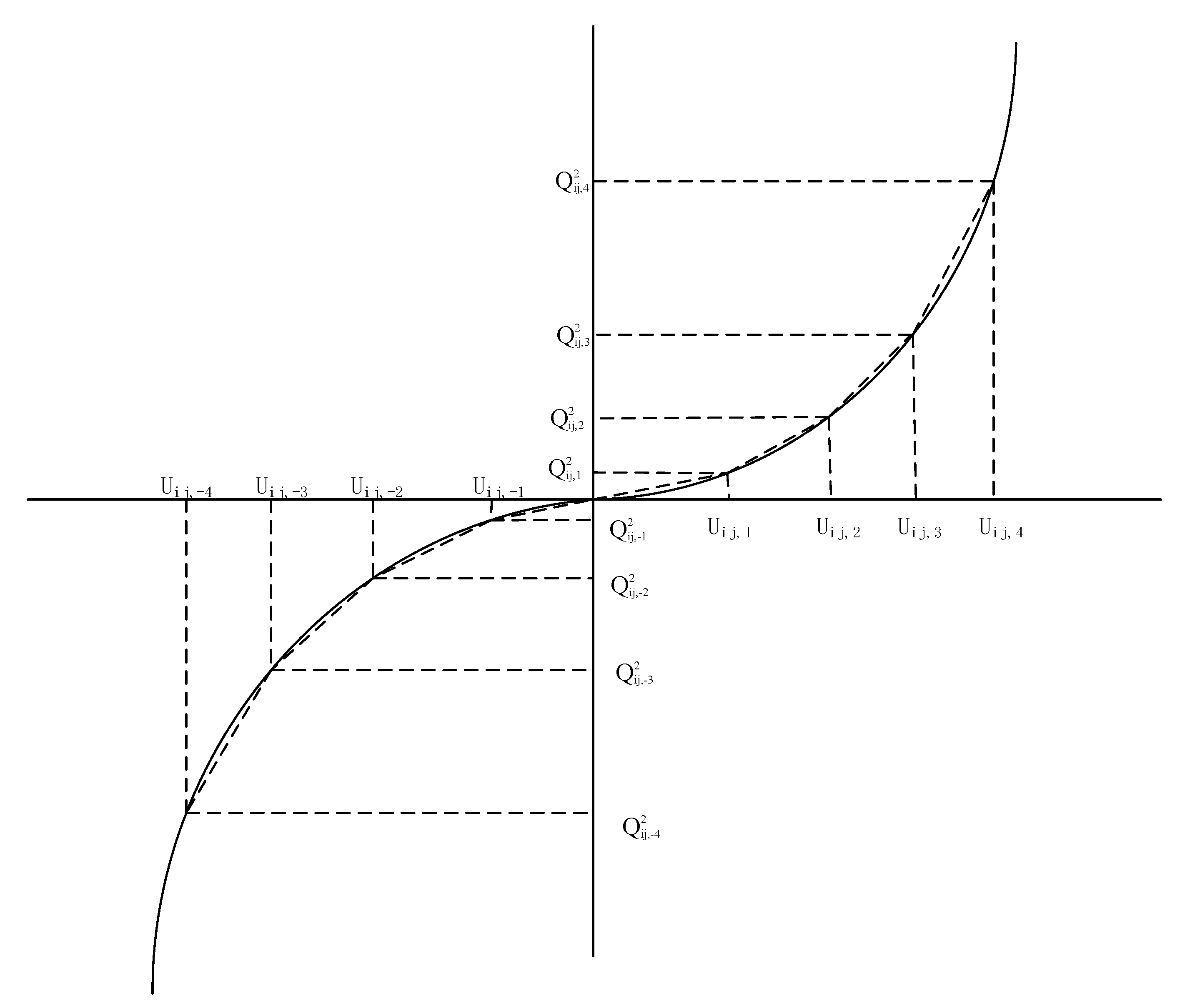
4.2. Linearization of Pipeline Flow in Natural Gas System

Square operation on both sides of the equation should be conducted for natural gas pipeline flow constraint with square roots, then:
[ Q i j g a s ( t ) ] 2 = K i j 2 | ( p i g a s ( t ) 2 ) ( p j g a s ( t ) 2 ) |
where the variables are set as p i g a s ( t ) 2 = π i g a s ( t ) and p j g a s ( t ) 2 = π j g a s ( t ) .
When sgn ( p i g a s , p j g a s ) is equal to 1, the Equation (28) can be converted to:
( Q i j g a s ( t ) ) 2 = K i j 2 [ π i g a s ( t ) π j g a s ( t ) ]
When sgn ( p i g a s , p j g a s ) is equal to −1, the Equation (28) can be converted to:
( Q i j g a s ( t ) ) 2 = K i j 2 [ ( π i g a s ( t ) π j g a s ( t ) ]
Quadratic term ( Q i j g a s ( t ) ) 2 still exists in the two equations above, thus piecewise linearization should be conducted shown as in Figure 3:
According to the procedures illustrated above, the model can be converted to mixed-integer planning problem and the CPLEX is adopted to realize the fast calculation.

5. Example Analysis

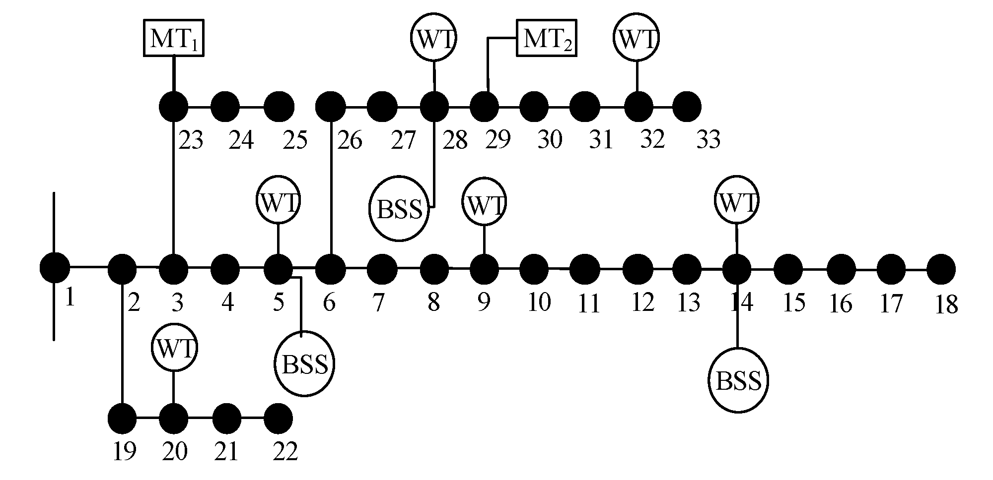
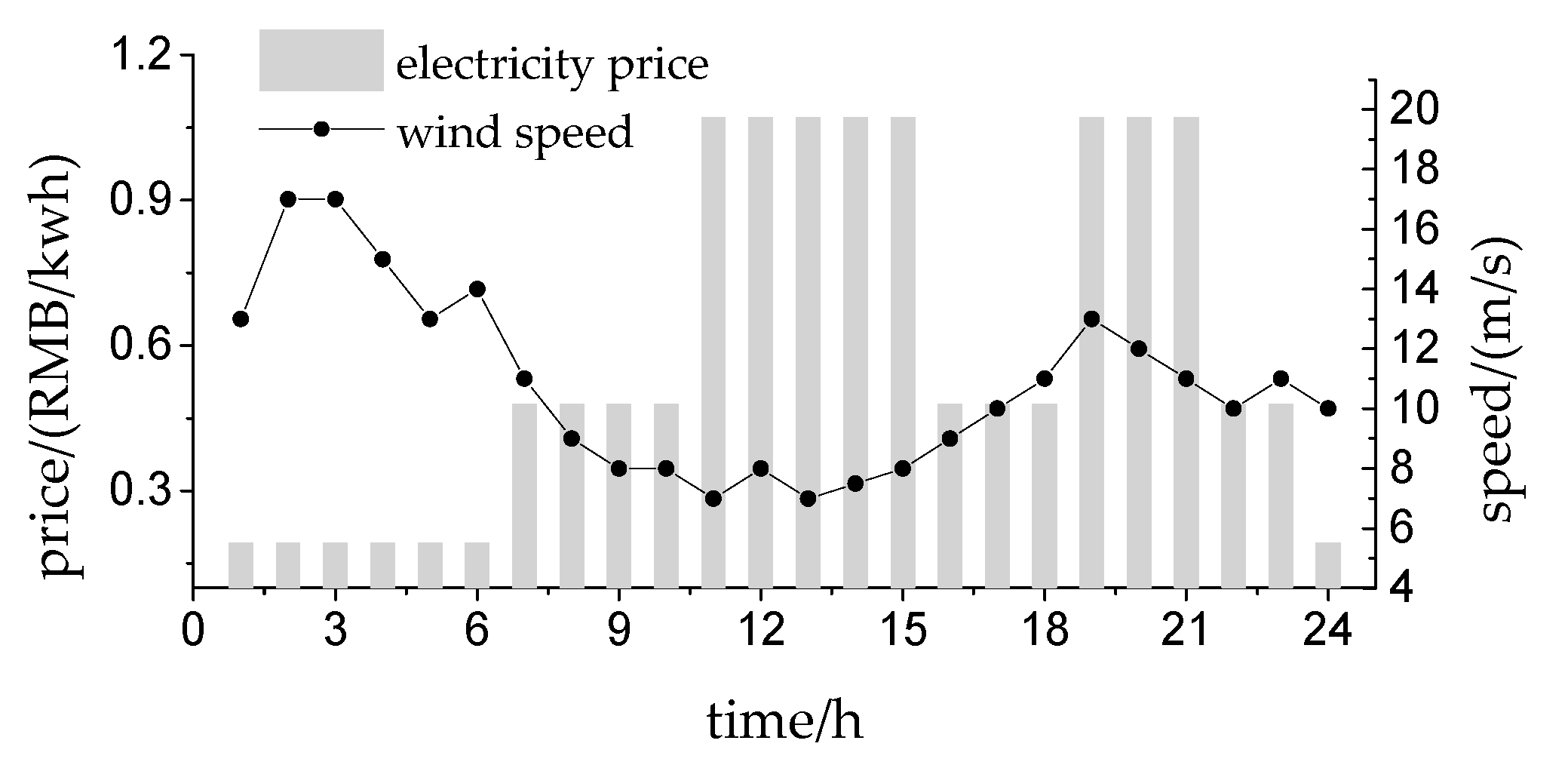
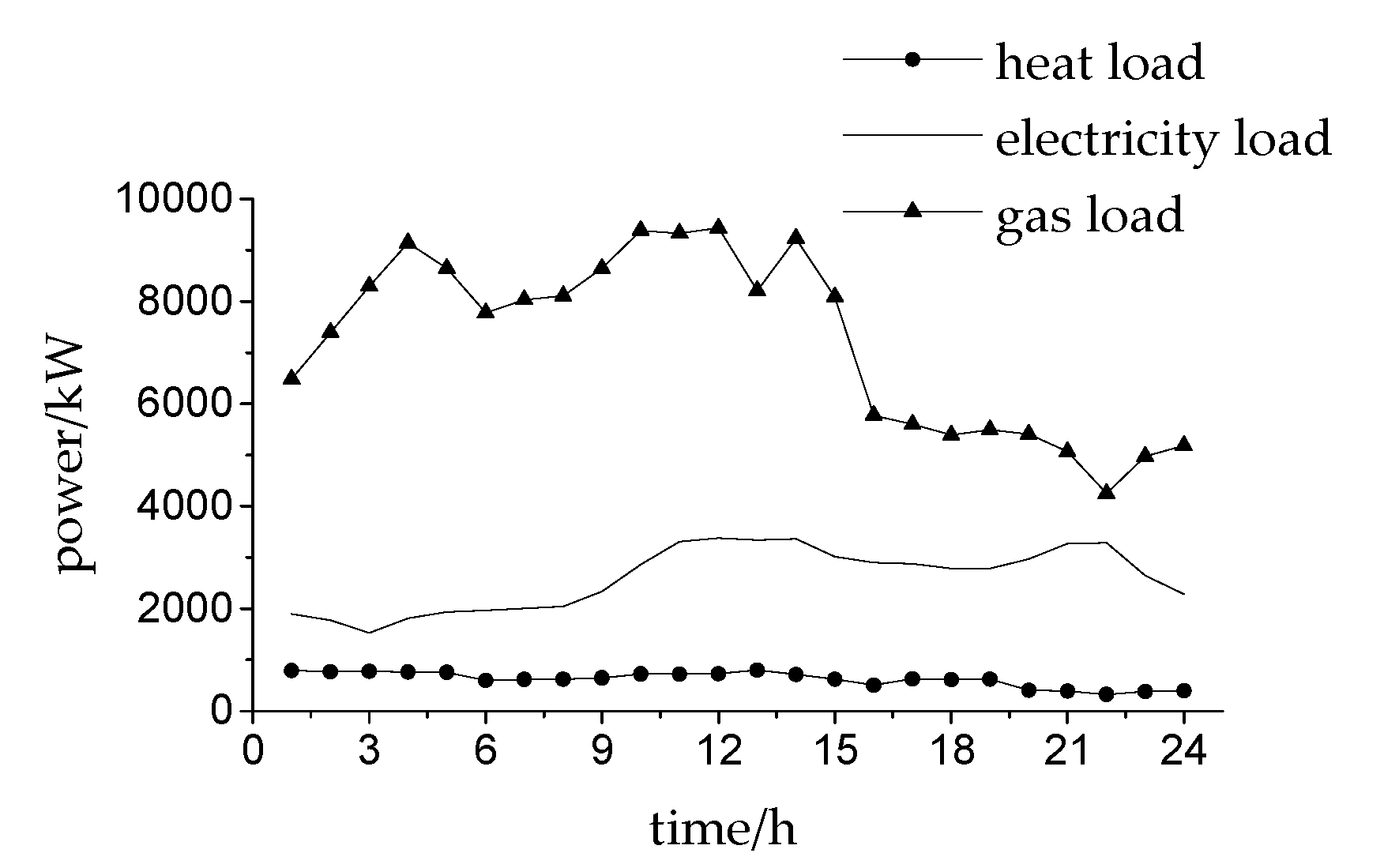
5.1. Composition of Example System

The IEEE 33-bus power system and modified 6-node natural gas system are used in example analysis in this paper, the power system structure is shown in Figure 4 and Figure 5. The natural gas price is set as 3.45 yuan/m3. Correlation parameters of single electric and thermal storage are listed in Table 1. Figure 6 shows the daily forecast values of electricity price and wind speed, where the nominal capacity of a wind turbine is assumed to be 500 kW, the cut-in wind speed is 5 m/s, the cut-off wind speed is 25 m/s, and the rated wind speed is 15 m/s. Figure 6 shows the data on electricity, heat and gas loads. The electricity price of network loss is set as 0.68 yuan/(kW⋅h).

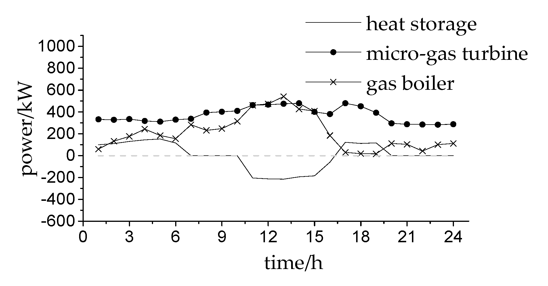
5.2. Result Comparison of Example Analysis

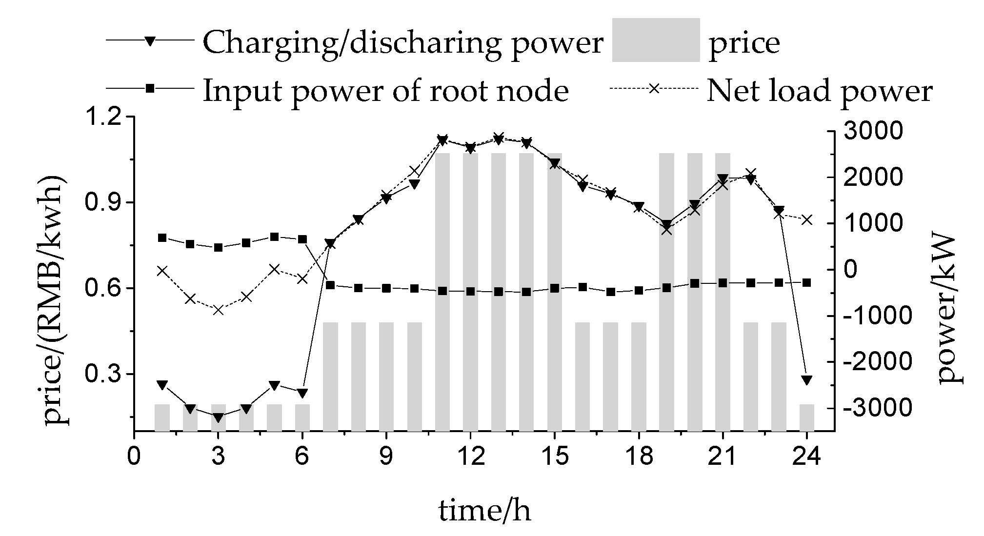
5.2.1. Result of Optimization When Wind Power Specific Permeability is 80%

In this analysis, the output of the distributed wind turbine is used as a priority to track and control the maximum power output. As the distributed wind turbine is connected to nodes 5, 9, 14, 20, 28 and 32 in the distributed network, the total cost of the regional integrated power system will be the lowest when the wind power specific permeability is 80%, the result of optimization is shown as Table 2. The node number of connected electricity storage is set as 3 and the number of heat storage is set as 2.
According to planning results, the regional integrated energy system invested a total of 15,274,000 yuan of the electricity storage device and 5,061,200 yuan of the thermal energy storage device. In the process of continuous solution for upper and lower functions, the capacity and location of the multi-energy storage can be determined, of which the network loss cost of the distributed network on a typical day is 798.35 yuan, and the total daily operating cost of the regional integrated system is 15,117 yuan.
Figure 7 shows the power purchase of the root node and the charge and discharge of the power storage device after the electricity storage devices are connected when the distribution network meets the satisfaction of the corresponding electricity load, where the net load represents the wind power output, which is the difference between the electricity load and 80% wind power specific permeability. It can be concluded that the root nodes do not purchase the electricity from the main network between the time period of 7–23 in the regional integrated energy system with multi-energy storage included. The energy supply can be balanced by the inner system storage itself. However, the load shifting in storage devices is still related to the price mechanism and the natural gas price is comprehensively considered. As the natural gas price is 0.3194 yuan/kWh after heat conversion, and is only higher than real-time electricity price during the time period of 1–6 and 24, the large volume of electricity storage will happen during the time period, while the discharge will happen when extra electricity prices are relatively high, thus to meet the regional load requirement.
Figure 8 shows power output plots of heat storage units, gas turbine units and gas boilers in the regional integrated power system. It can be concluded that the output fluctuation of the gas turbine is rather limited due to its characteristic in “the electricity is defined by the heat”. When the real-time price is lower than the natural gas price, like during the time period 1–6, the system will release heat from the heat storage and lower the gas consumption in gas turbine and gas boiler when the heat load in the system is within satisfaction; when the real-time price is higher than the natural gas price, like during time period of 11–15, the system will enhance the output of the gas turbine and gas boiler for energy storage with further energy release at a later time period by adopting the heat storage device.

5.2.2. Result of Optimization When Wind Power Specific Permeability is 30%

To test the applicability of the regional integrated energy system under low-wind power specific permeability, the optimization calculation of the regional integrated power system under the output power whose wind power specific permeability is 30% in grid connection is conducted with the goal of minimum cost in the integrated system, which can be shown in Table 3.
According to planning results, a total of 16,017,000 yuan of the electricity storage device and 5,332,700 yuan of the thermal energy storage device were invested in the regional integrated energy system. The net loss cost for the distributed network under typical days is 1196 yuan, while the total operating cost in regional integrated system in typical days is 23,012 yuan. Namely, under the low wind power specific permeability, the integrated system will invest more electricity storage and heat storage devices, and the costs in each kind will increase relatively on typical days.
Figure 9 shows the power purchase of root nodes and charge and discharge of the electricity storage under low wind power specific permeability. As the wind power specific permeability is low, the power purchase is obviously surging when the real-time price is low during the time periods of 1–6 and 22–24 in the integrated system. This is due to the satisfaction of net load requirement and electric charge for the storage. During the time periods of 11–15 and 19–21, when the electricity price is rather high, the system will sell electricity to the main network, and the electricity will discharge from the electricity storage to lower the total operating cost under the prerequisite of electricity load satisfaction.
Figure 10 shows the output plot of the heat storage, gas turbine and gas boiler in the regional integrated power system with low wind power specific permeability. Compared with the output result with high wind power specific permeability, the output power of gas turbine is increased but with rather low adjustability. The power of the heat storage device during heat storage and release is enhanced to decrease the operating cost in the integrated system and to increase the adjustability of the system.

5.2.3. Economic Analysis without Heat Storage Device

Multi-energy storage devices discussed in this paper are mainly electricity storage device and heat storage devices. In this section, the economy of the regional integrated power system under various operating modes will be discussed under the comparison between total investment cost and operating cost with and without the heat storage devices, whose results are shown in Table 4. The wind power specific permeability under the multi-energy storage condition is set to be as high as 80%.
In the regional integrated power system with multi-energy storage devices, the total daily operating cost in the system can be lowered with 3070 yuan, and the investment cost for the heat storage device can be recovered within 3–4 years without bank rate.

6. Conclusions

Based on the regional integrated power system, the original model is converted to the linear optimized model by second-order conic relaxation and piecewise linearization on the basis of the non-linear double-layer model of multi-energy storage configuration with power flow constraint in power grid and natural gas pipeline flow constraint. In the proposed double-layer model, the upper planning layer aims to minimize the integrated investment cost in the multi-energy storage; while the lower layer aims to minimize the total operating cost in the regional integrated energy system. Moreover, economic problems under various wind power specific permeabilities in the distributed wind power grid are discussed, and the detailed comparison of active power optimization results are made between devices and multi-energy storages in the regional integrated power system. Conclusions are as follows:
(1)
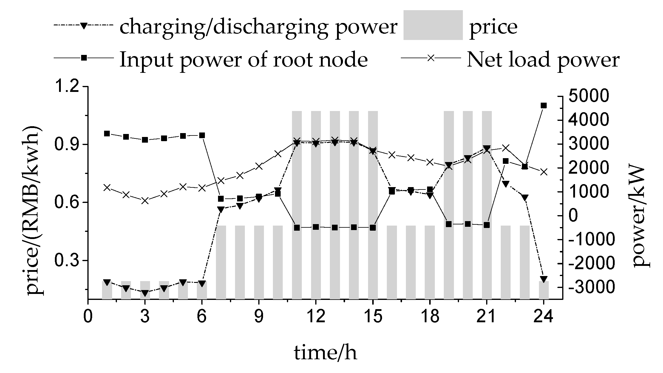
The energy should be provided by the regional integrated power system to the distributed wind power when the wind power specific permeability is high in grid connection. When the natural gas price is lower than the real-time electricity price, it is not necessary to purchase electricity from the main network, while various load requirements can be met by natural gas turbine units and multi-energy storage devices.
(2)
During the time period when the real-time price is lower than the natural gas price in the regional integrated power system whose wind power specific permeability is low, the electricity should be purchased in a large volume from the main network and the electricity should be stored by the electricity storage device to release the energy in other time periods, thus to lower the operating costs.
(3)
The total operating cost in the regional integrated energy system will be lower when the multi-energy storage is taken into consideration, and extra investment costs can be recovered within one year, so it shares a higher economy.
Discussion: This paper focuses on the modeling and problem solving for the optimization configuration of multi-energy storage in the regional integrated energy system with distributed wind power. The next step will mainly focus on the modeling for mathematical problems in the dynamic characteristics of electricity storage, thermal storage device, energy loss and each energy system.
This paper comprehensively considers the characteristic of multi-energy storage to establish a double-stage comprehensive optimization model, which contributes to the planning problem of multi-energy storage in regional integrated energy systems under different wind power penetration rates, making the planning decision results of energy storage more reasonable.

Author Contributions

Conceptualization, Q.Z. and Z.R.; methodology, Q.Z. and Z.R.; software, R.M.; formal analysis, M.T.; supervision, Z.H.

Funding

This work was funded by the National Key R&D Program of China, grant number 2018YFB0905200 and the science project of State Grid Sichuan Electric Power Corporation, grant number SGTYHT/18-JS-199.

Acknowledgments

This work was supported by the National Key R&D Program of China (2018YFB0905200) and the science project of State Grid Sichuan Electric Power Corporation (SGTYHT/18-JS-199).

Conflicts of Interest

The authors declare no conflict of interest.

Nomenclature

Indices
tTime (hours)
τ Time (days)
nTime (years)
i,j,kbranch line number
ddemand
Constants
C i n s e , e l e electricity storage capacity investment cost
C m , e l e electricity storage capacity maintenance cost
C i n s e , h heat storage capacity investment cost
C m , h heat storage capacity maintenance cost
Mdepreciation life of the energy storage
rdepreciation rate
E P min minimum capacity value of electricity storage
E P max maximum capacity value of electricity storage
E H min minimum capacity value of heat storage
E H max maximum capacity value of heat storage
P wind , min minimum output value of distributed wind turbine
P wind , max maximum output value of distributed wind turbine
P max maximum power of electricity storage
H max maximum power of heat storage
vrrated wind speed
Prrated output power of distributed wind turbine
η wind permeability value of distributed wind power
α c electricity storage charge factors
α d electricity storage discharge factors
β c h a r heat storage charge factors
β d i s heat storage discharge factors
λ e l e electricity price
λ g a s natural gas price
λ g a s value of total nodes
Nvalue of total nodes
K loss net loss electricity price
rijresistance of branch ij
P d electricity demand
H d heat demand
Q d gas demand
I _ minimum value of the branch current
I ¯ maximum value of the branch current
Kijnatural gas pipeline parameter
p i min minimum value of the pressure value
p i max maximum value of the pressure value
η G B conversion efficiency of gas boiler
η MT conversion efficiency of gas turbine
η r e s MT waste heat recycling efficiency
K h 0 heating coefficient
Hhigh thermal value of natural gas
Variables
COCthe operating cost of upper layer
E P capacity value of electricity storage
E H capacity value of heat storage
P wind output of distributed wind turbine
vicut-in wind speed
vocut- out wind speed
I char charging binary marker variable
I dis discharging binary marker variable
P dis charging power of electricity storage
P char charging power of electricity storage
H d i s discharging power of heat storage
H c h a r charging power of heat storage
H d G B heat power of gas boiler
H d MT heat power of gas turbine
I i j current of line ij
P G r i d power purchase from the main grid
P d MT output power of gas turbine
Q d MT natural gas consumption of gas turbine
Q d G B natural gas consumption of gas boiler
Q G r i d natural gas supplied from natural gas sources
Q i j g a s natural gas pipeline flow of ij
p g a s pipeline pressure

References

  1. Franz, F. The third Industrial Revolution. Int. Study Ref. 2012, 6, 8–11. [Google Scholar]
  2. Wang, D.; Liu, L.; Jia, H.; Wang, W.; Zhi, Y.; Meng, Z.; Zhou, B. Tianjin University Review of key problems related to integrated energy distribution systems. CSEE J. Power Energy Syst. 2018, 4, 130–145. [Google Scholar] [CrossRef]
  3. Tian, S.; Luan, W.; Zhang, D. Form and Key Technology of Energy Interconnection. Proc. Chin. Soc. Electr. Eng. 2015, 3, 3482–3494. [Google Scholar]
  4. Zakeri, B.; Syri, S. Electrical energy storage systems: A comparative life cycle cost analysis. Renew. Sustain. Energy Rev. 2015, 42, 569–596. [Google Scholar] [CrossRef]
  5. Larcher, D.; Tarascon, J. Towards greener and more sustainable batteries for electrical energy storage. Nat. Chem. 2015, 7, 19. [Google Scholar] [CrossRef] [PubMed]
  6. Jiang, Q.; Gong, Y.; Wang, H. A battery energy storage system dual-layer control strategy for mitigating windfarm fluctuations. IEEE Trans. Power Syst. 2013, 28, 3263–3273. [Google Scholar] [CrossRef]
  7. Yuan, Y.; Zhang, X.S.; Ju, P.; Li, Q.; Qian, K.; Fu, Z. Determination of economic dispatch of wind farm-battery energy storage system using genetic algorithm. Int. Trans. Electr. Energy Syst. 2014, 24, 264–280. [Google Scholar] [CrossRef]
  8. Li, J.; Tian, L.; Lai, X. Outlook of electrical energy storage technologies under energy internet background. Autom. Electr. Power Syst. 2015, 39, 15–25. [Google Scholar]
  9. Hartmann, B.; Dan, A. Cooperation of a grid-connected wind farm and an energy storage unit-demonstration of a simulation tool. IEEE Trans. Sustain. Energy 2012, 3, 49–56. [Google Scholar] [CrossRef]
  10. Yang, J.; Zhang, N.; Cheng, Y.; Kang, C.; Xia, Q. Modeling the Operation Mechanism of Combined P2G and Gas-fired Plant with CO2 Recycling. IEEE Trans. Smart Grid 2019, 10, 1111–1121. [Google Scholar] [CrossRef]
  11. Zhao, B.; Conejo, A.J.; Sioshansi, R. Unit Commitment Under Gas-Supply Uncertainty and Gas-Price Variability. IEEE Trans. Power Syst. 2017, 32, 2394–2405. [Google Scholar] [CrossRef]
  12. Zheng, J.H.; Wu, Q.H.; Jing, Z.X. Coordinated scheduling strategy to optimize conflicting benefits for daily operation of integrated electricity and gas networks. Appl. Energy 2016, 192, 370–381. [Google Scholar] [CrossRef]
  13. Mago, P.; Chamra, L. Analysis and optimization of CCHP systems based on energy, economical, and environmental considerations. Energy Build. 2009, 41, 1099–1106. [Google Scholar] [CrossRef]
  14. Li, J.; Tian, L.; Lai, X. Prospect of power storage technology under Energy Interconnection. Autom. Electr. Power Syst. 2015, 18, 15–25. [Google Scholar]
  15. Wang, C.; Liu, H.; Gong, J. Multi-type Energy Storage Joint Dispatch for Wind Power Elimination. Electr. Power Constr. 2018, 39, 35–44. [Google Scholar]
  16. Kwasinski, A.; Krishnamurthy, V.; Song, J.; Sharma, R. Availability Evaluation of Micro-Grids for Resistant Power Supply During Natural Disasters. IEEE Trans. Smart Grid 2012, 3, 2007–2018. [Google Scholar] [CrossRef]
  17. Wang, D.; Zhi, Y.; Yu, B.; Chen, Z.; An, Q.; Cheng, L.; Fan, M.; Tianjin University; China Electric Power Research Institute; State Grid Tianjin Electric Power Corporation. Optimal coordination control strategy of hybrid energy storage systems for tie-line smoothing services in integrated community energy systems. CSEE J. Power Energy Syst. 2018, 4, 408–416. [Google Scholar] [CrossRef]
  18. Shabanpour-Haghighi, A.; Seifi, A.R. Multi-objective operation management of a multi-carrier energy system. Energy 2015, 88, 430–442. [Google Scholar] [CrossRef]
  19. Beigvand, S.D.; Abdi, H.; La Scala, M. Optimal operation of multicarrier energy systems using Time Varying Acceleration Coefficient Gravitational Search Algorithm. Energy 2016, 114, 253–265. [Google Scholar] [CrossRef]
  20. Sedghi, M.; Ahmadian, A.; Aliakbar-Golkar, M. Optimal Storage Planning in Active Distribution Network Considering Uncertainty of Wind Power Distributed Generation. IEEE Trans. Power Syst. 2015, 31, 1–13. [Google Scholar] [CrossRef]
  21. Giannitrapani, A.; Paoletti, S.; Vicino, A.; Zarrilli, D. Optimal allocation of energy storage systems for voltage control in LV distribution networks. IEEE Trans. Smart Grid 2017, 8, 2859–2870. [Google Scholar] [CrossRef]
  22. Zhang, L.; Tang, W.; Cong, P. Comprehensive Optimized Allocation for Active and Reactive Power in Distributed Network with Photovoltaic Power Generation. Proc. Chin. Soc. Electr. Eng. 2014, 8, 5525–5533. [Google Scholar]
  23. Gao, H.; Liu, J. Collaborative Planning of Active Distributed Network that Considers Various Types of DG and Load Modelling. Proc. Chin. Soc. Electr. Eng. 2016, 36, 4911–4922. [Google Scholar]
  24. Dai, Y.; Chen, L.; Min, Y.; Mancarella, P.; Chen, Q.; Hao, J.; Hu, K.; Xu, F. A General Model for Thermal Energy Storage in Combined Heat and Power Dispatch Considering Heat Transfer Constraints. IEEE Trans. Sustain. Energy 2018, 9, 1518–1528. [Google Scholar] [CrossRef]
  25. Bansal, A.; Kumar, A.; Kumar, N. Optimization of radial distribution system losses with wind weibull distribution function integration using PSO and GA technique. In Proceedings of the 2016 7th India International Conference on Power Electronics (IICPE), Patiala, India, 17–19 November 2016. [Google Scholar]
  26. Lu, Z.; Sui, Y.; Feng, T. Wind Power Consumption with Low-carbon Economy Scheduling that Considers Heat Storage and Carbon-trapping Equipment. Trans. China Electrotech. Soc. 2016, 31, 1418–1428. [Google Scholar]
  27. Pandey, A.; Jereminov, M.; Wagner, M.R.; Bromberg, D.M.; Hug, G.; Pileggi, L. Robust Power Flow and Three Phase Power Flow Analyses. IEEE Trans. Power Syst. 2019, 34, 616–626. [Google Scholar] [CrossRef]
  28. He, Y.; Shahidehpour, M.; Li, Z.; Guo, C.; Zhu, B. Robust Constrained Operation of Integrated Electricity- Natural Gas System Considering Distributed Natural Gas Storage. IEEE Trans. Sustain. Energy 2018, 9, 1061–1071. [Google Scholar] [CrossRef]
  29. Salimi, M.; Adelpour, M.; Vaez-Zadeh, S.; Ghasemi, H. Optimal planning of energy hubs in interconnected energy systems: A case study for natural gas and electricity. IET Gener. Transm. Distrib. 2015, 9, 695–707. [Google Scholar] [CrossRef]
  30. Cui, Y.; Chen, Z.; Yan, G. Coordinated Wind Power Accommodating Dispatch Model Based on Electric Boiler and CHP with Thermal Energy Storage. Proc. Chin. Soc. Electr. Eng. 2016, 36, 4072–4080. [Google Scholar]
  31. Li, H.; Cui, H.; Wan, Q. Distribution Network Reconfiguration based on Second-order Conic Programming Considering EV Charging Strategy. Proc. Chin. Soc. Electr. Eng. 2015, 35, 4674–4681. [Google Scholar]
Figure 1. The structure of Regional Integrated Energy System.
Energies 12 03964 g001
Figure 2. The framework of the bi-level optimization model.
Energies 12 03964 g002
Figure 3. The diagrammatic drawing of piecewise linearization. Where Uij,n (n = −1,1,−2,2,…) are all auxiliary variables which are 0–1.
Energies 12 03964 g003
Figure 4. Structure diagram of IEEE 33-bus distribution network.
Energies 12 03964 g004
Figure 5. The curves of electricity price and forecast wind speed.
Energies 12 03964 g005
Figure 6. The curves of electricity, heating and gas loads.
Energies 12 03964 g006
Figure 7. The curves of the ESS charge power and the power supplied by the distribution network.
Energies 12 03964 g007
Figure 8. The optimization results of the heating system.
Energies 12 03964 g008
Figure 9. The curves of the ESS charge power and the power supplied by the distribution network.
Energies 12 03964 g009
Figure 10. The optimization results of the heating system.
Energies 12 03964 g010
Table 1. Parameters of one storage unit.
ParametersElectricity StorageThermal Storage
Nominal capacity/(W·h)1000400
Maximum charge and discharge power/W500200
Initial capacity/(W·h)500200
Investment cost/(yuan/W·h)1.5211.39
Operating and maintenance cost/(yuan/W·h)0.0030.002
Life cycle/year1010
Bank rate0.050.0475
Table 2. Planning Results.
CategoryLocationStorage Capacity/(MW·h)Total Cost for Storage Investment/yuanElectricity Purchase Cost from Main Network/yuanGas Purchase Cost Net Loss Cost/yuan Total Daily Operating Cost/yuan
Electricity storage526.87715,274,0004927.23874.3798.3515,117
165.419
279.552
Heat storage-36.3135,061,200
-36.434
Table 3. Planning Results.
CategoryLocationStorage Capacity/(MW·h)Total Cost for Storage Investment/yuan Electricity Purchase Cost from Main Network/yuanGas Purchase Cost/yuanNet Loss Cost/yuanTotal Daily Operating Cost/yuan
Electricity storage534.05316,017,00012,2225191.8119623,012
163.959
275.869
Heat storage-38.285,332,700
-38.37
Table 4. The investment and operation cost of the regional integrated energy system under two scenarios.
Without Heat Storage Devices (Unit:/yuan)With Heat Storage Devices (Unit:/yuan)
Total investment costDaily operating costTotal investment costDaily operating cost
16,028,00018,18720,335,20015,117

